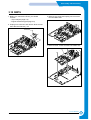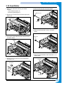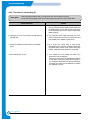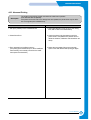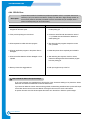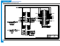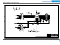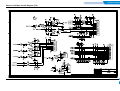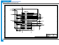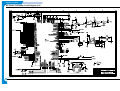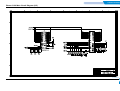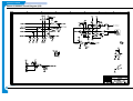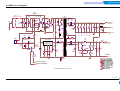
1
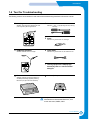
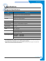
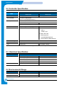
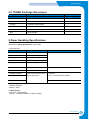
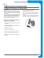
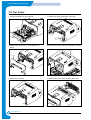
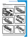
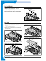
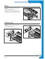
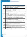
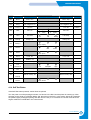
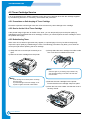
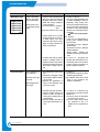
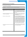
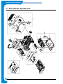
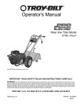
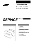
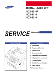
LASER PRINTER
Phaser 3120
Phaser 3130
SERVICE
LASER PRINTER
Manual
CONTENTS
1. Precautions
2. Specifications
3. Disassembly and Reassembly
4. Troubleshooting
5. Exploded Views and Parts List
6. Block Diagram
7. Connection Diagram
8. Schematic Diagram
Precautions
1
1. Precautions
The cautions in the below are items needed to keep in mind when maintaining and servicing.
Please read carefully and keep the contents in mind to prevent accidents while servicing and to prevent
that the machine gets damage.
1.1 Warning for safety.
(1) Request the service by qualified service person.
The service for this machine must be performed by a service person who took the additional education of
this field.
It is dangerous if unqualified service person or user tries to fix the machine.
(2) Do not rebuild it discretionary.
Do not attach or change pats discretionary. Do not dissemble, fix, and rebuilt it. If do, printer will abnormally
work and electric shock or a fire can be occurred.
(3) Laser Safety Statement
The Printer is certified in the U.S. to conform to the requirements of DHHS 21 CFR, chapter 1 Subchapter J
for Class 1(1) laser products, and elsewhere, is certified as a Class I laser product conforming to the
requirements of IEC 825.
Class I laser products are not considered to be hazardous. The laser system and printer are designed so
there is never any human access to laser radiation above a Class I level during normal operation, user
maintenance, or prescribed service condition.
Warning >> Never operate or service the printer with the protective cover removed from Laser/Scanner assembly. The reflected
beam, although invisible, can damage your eyes. When using this product, these basic safety precautions should
always be followed to reduce risk of fire, electric shock, and injury to persons.
CAUTION - INVISIBLE LASER RADIATION
WHEN THIS COVER OPEN.
DO NOT OPEN THIS COVER.
VORSICHT - UNSICHTBARE LASERSTRAHLUNG,
WENN ABDECKUNG GE FFNET.
NICHT DEM STRAHL AUSSETZEN.
ATTENTION - RAYONNEMENT LASER INVISIBLE EN CAS
D OUVERTURE. EXPOSITION DANGEREUSE
AU FAISCEAU.
ATTENZIONE - RADIAZIONE LASER INVISIBILE IN CASO DI
APERTURA. EVITARE L ESPOSIZIONE AL
FASCIO.
PRECAUCION - RADIACION LASER IVISIBLE CUANDO SE ABRE.
EVITAR EXPONERSE AL RAYO.
ADVARSEL. - USYNLIG LASERSTR LNING VED BNING, N R
SIKKERHEDSBRYDERE ER UDE AF FUNKTION.
UNDG UDSAETTELSE FOR STR LNING.
ADVARSEL. - USYNLIG LASERSTR LNING N R DEKSEL
PNES. STIRR IKKE INN I STR LEN.
UNNG EKSPONERING FOR STR LEN.
VARNING - OSYNLIG LASERSTR LNING N R DENNA DEL
R PPNAD OCH SP RREN R URKOPPLAD.
BETRAKTA EJ STR LEN. STR LEN R FARLIG.
VARO! - AVATTAESSA JA SUOJALUKITUS OHITETTAESSA
OLET ALTTIINA N KYM TT M LLE LASERS TEILYLLE L KATSO S TEESEEN.
Service Manual
1-1
Precautions
1.2 Caution for safety
1.2.1 Precaution related noxious material
The toner in a printer cartridge contains a chemical material, which might harm human body if it is swallowed.
Please keep children out of the toner cartridge.
1.2.2 Precaution related electric shock or fire
It is possible to get electric shock or burn by fire if you don't fallow the instructions of the manual.
(1) Use exact voltage. Please do use an exact voltage and wall socket. If not, a fire or an electric leakage can
be caused.
(2) Use authorized power code. Do use the power code supplied with PRINTER. A fire can be occurred when
over current flows in the power code.
(3) Do not insert many codes in an outlet. If do, a fire can be occurred due to flow over current in an outlet.
(4) Do not put water or extraneous matter in the PRINTER. Please do not put water, other liquid, pin, clip, etc.
It can cause a fire, electric shock, or malfunction. If it is happened, turn off the power and remove the
power plug from outlet immediately.
(5) Do not touch the power plug with wet hand. When servicing, do remove the power plug from outlet. And
do not insert or take off it with wet hand. Electric shock can be occurred.
(6) Caution when inserting or taking off the power plug. The power plug has to be inserted completely. If not,
a fire can be caused due to poor contact. When taking off the power plug, do grip the plug and take it off.
If grip the line and pull over, it could be damaged. A fire or electric shock could cause.
(7) Management of power code. Do not bend, twist, or bind it and place other materials on it. Also, do not fix
it with staples. If the power code gets damage, a fire or electric shock can be caused. A damaged power
code must be replaced immediately. Do not repair the damaged part and reuse it. A repaired part with plastic tape can be occurred a fire or electric shock. Do not spread chemicals on the power code. Do not
spread insecticide on the power code. A fire or electric shock can be occurred due to thinner(weak) cover
of the power code.
(8) Check whether the power outlet and the power plug are damaged, pressed, chopped, or blazing fire or
not. When such inferiorities are found, repair it immediately. Do not make it pressed or chopped when
moving the machine.
(9) Caution when thundering, and being flash of lightening. It causes a fire or electric shock. Take the power
plug off when thundering. Do not touch cable and device when thundering and being flash of lightening.
(10) Do avoid the place where is moisture or has dust. Do not install the printer in where have lots of dust or
around humidifier. A fire can be occurred. A plug part need to clean well with dried fabric to remove dust.
If water drops are dripped on the place covered with dust, a fire can be occurred.
(11) Avoid direct sunlight. Do not install the printer near to window where directly contacts to the sunlight. If
the machine contacts sunlight long time, the machine cannot work properly because inner temperature
of the machine is getting higher. A fire can be caused.
(12) Turn off the power and take off the plug when a smoke, strange smell, or sound from the machine. If you
keep using it, a fire can be occurred.
(13) Do not insert steel or metal piece inside/outside of the machine. Do not put steel or metal piece into a
ventilator. An electric shock could be happened.
1-2
Service Manual
Precautions
1.2.3 Precaution related handling the machine.
If you ignore this information, you could get harm and machine could be damaged.
(1) Do not install it on the different levels, or slanted floor.
Please confirm whether it is balanced or not after installation. If it is unbalanced, an accident can be happened due to the machine fell over.
(2) Be careful not to insert a finger or hair in the rotating unit.
Be careful not to insert a finger of hair in the rotating unit (motor, fan, paper feeding part, etc) while the
machine is operating. Once it happens, you could harm.
(3) Do not place a pot contains water/chemical or small metals. If those are got into the inner side of machine,
a fire or electric shock can be occurred.
(4) Do not install it in where lots of moisture or dust exists or where raindrop reaches. A fire or electric shock
can be caused.
(5) Do not place a candlelight, burning cigarette, and etc. on the machine. Do not install it near to heater. A
fire can be occurred.
1.2.4 Precaution when assembly/disassembly
When replace parts, do it very carefully. Do memorize the location of each cable before replace parts for
reconnecting it afterwards. Do memorize. Please perform the below before replace or disassembly the parts.
(1) Check the contents stored in the memory. All the information will be erased after replace main board. The
information needed to keep has to be written down.
(2) Before servicing or replacing electric parts, take off a plug.
(3) Take off printer cables and power code connected to printer.
(4) Do use formal parts and same standardized goods when replacing parts.Must check the product name,
part code, rated voltage, rated current, operating temperature, etc.
(5) Do not give an over-force when release or tighten up the plastic parts.
(6) Be careful not to drop the small parts such as screws in the printer.
(7) Be careful not to change the location of small parts such as screws when assembling and disassembling.
(8) Do remove dust or foreign matters completely to prevent fire of tracking, short, or etc.
(9) After finished repair, check the assembling state whether it is same as before the repair or not.
Service Manual
1-3
Precautions
1.3 ESD Precautions
Certain semiconductor devices can be easily damaged by static electricity. Such components are commonly
called “Electrostatically Sensitive (ES) Devices”, or ESDs. Examples of typical ESDs are: integrated circuits,
some field effect transistors, and semiconductor “chip” components.
The techniques outlined below should be followed to help reduce the incidence of component damage caused
by static electricity.
Caution >>Be sure no power is applied to the chassis or circuit, and observe all other safety precautions.
1. Immediately before handling a semiconductor component or semiconductor-equipped assembly, drain off
any electrostatic charge on your body by touching a known earth ground. Alternatively, employ a commercially available wrist strap device, which should be removed for your personal safety reasons prior to applying power to the unit under test.
2. After removing an electrical assembly equipped with ESDs, place the assembly on a conductive surface,
such as aluminum or copper foil, or conductive foam, to prevent electrostatic charge buildup in the vicinity
of the assembly.
3. Use only a grounded tip soldering iron to solder or desolder ESDs.
4. Use only an “anti-static” solder removal device. Some solder removal devices not classified as “anti-static”
can generate electrical charges sufficient to damage ESDs.
5. Do not use Freon-propelled chemicals. When sprayed, these can generate electrical charges sufficient to
damage ESDs.
6. Do not remove a replacement ESD from its protective packaging until immediately before installing it. Most
replacement ESDs are packaged with all leads shorted together by conductive foam, aluminum foil, or a
comparable conductive material.
7. Immediately before removing the protective shorting material from the leads of a replacement ESD, touch
the protective material to the chassis or circuit assembly into which the device will be installed.
8. Maintain continuous electrical contact between the ESD and the assembly into which it will be installed,
until completely plugged or soldered into the circuit.
9. Minimize bodily motions when handling unpackaged replacement ESDs. Normal motions, such as the
brushing together of clothing fabric and lifting one’s foot from a carpeted floor, can generate static electricity sufficient to damage an ESD.
1-4
Service Manual
Precautions
1.4 Tool for Troubleshooting
The following tools are recommended for safe and smooth troubleshooting described in this service manual.
1 DCU(Diagnostic Control Unit)
Standard : Test equipment to diagnose the Laser
printer supplied by Samsung Electronics.
4 Driver
Standard : "-" type, "+" type (M3 long, M3 short, M2 long,
M2 short).
5 Pinset
Standard : For general home use, small type.
2 DVM(Digital Volt Meter)
Standard : Indicates more than 3 digits.
6 Cotton Swab
Standard : For general home use, for medical ser-vice
7 Cleaning Equipments a IPA(Isopropyl
Alcohol)dry cloth or a soft stuff neutral
detergent
3 Electronic Scale
8 Software(Driver) installation CD ROM
Standard : Equipment to check the weight of consumables(toner cartridge) supplied by Samsung
Electronics. (The gram unit can be measured.)
Mind your hands not to be touched when you
disassemble and reassemble PBA ASS'Y, such
as the main board, SMPS, HVPS.
Service Manual
1-5
Specifications
2
2. Specifications
2.1 General Specifications
ITEM
DESCRIPTION
Print Technology
Non-impact Electro-photograpic Printing
Developing system
Non-Magnetic, Mono-Component Developing System
Print Speed(1)
16 PPM : A4 size , 5% Character pattern
17 PPM : Letter size , 5% Character pattern
Resolution
Phaser 3120 : True 600 X 600 DPI
Phaser 3130 : 1200 X 600 DPI
Source of Light
Laser diode (LSU : Laser Scanner Unit)
Warm-Up Time
Power-on boot : 30 seconds or less
First Print Out Time
Less than 11 seconds (Ready to 1st page out)
Media Size
75 X 125 (3” X 5”) mm to 216 X 356 (8.5” X 14”)mm
Media Thickness
16 ~ 24 lb
Dimension(W X D X H)
348 X 355 X 193mm / 13.7 X 14 X 7.6 inch
Weight
Net : 7 Kg /15.4 lb
Gross : 9.5 Kg (Max.)
Acoustic Noise
(1)
Stand by : Less than 35 dB
Printing: Less than 50 dB
Machine Life
120,000 Sheets
Periodic Replacing Parts(2)
Pick Up Roller :
60,000 Sheets
Feed Roller
:
60,000 Sheets
Transfer Roller:
60,000 Sheets
Fuser Assembly : 60,000 Sheets
(1)
(2)
For measuring the printing speed, count the papers which outputted within one minute from when the
second page starts to be printed. (A4, 5% character pattern standard)
The life span of the consumption parts can be checked by printing the demo page or the system list.
(Refer to the 6.3 Receive the service information)
Service Manual
2-1
Specifications
2.2 Controller Specification
DESCRIPTION
ITEM
Phaser 3120
Processor(CPU)
Phaser 3130
Samsung Jupiter4 90MHz
OS Compatibility
(1)
Samsung SPGPm 166MHz
Win 98x/NT4.0/ME/2000/XP,
Various Linux OS,Mac(Mac OS 8.6 ↑)
Memory
FLASH ROM(PROGRAM) : 0.5MB flash
RAM : 8 MB
RAM : 32 MB
EEPROM(NVRAM) : 512byte
Emulation
SPL(Samsung Printer Language)
PCL6, IBMProPrinter, EPSON
Interface
USB 1.1
USB
- USB 2.0
- 12 Mbps 1 port
Parallel : IEEE 1284
- Modes supported :
Compatible,Nibble,Byte,ECP
External Network Adaptor(Optional)
Interface switching
Automatic
Interface time-out
5min(Max.)
Font
Windows Font
45 Scalable, 1 Bitmap
(1) The SPL series model is USB exclusive use, so it supports the environment beyond the WIN 98.
2.3 Electrical Specification
ITEM
Input Voltage
Power Consumption
DESCRIPTION
Nominal input voltage
200-240 VAC / 100~127VAC
Input voltage range
189-264 VAC/ 90~132VAC
Nominal frequency
50/60 Hz
Frequency tolerance
+3Hz
Printing : 280W Avg or less
Power Save : 10W Avg or less
2.4 Environmental Range
ITEM
2-2
OPERATING
STORAGE
Temperature
10~32 C(50-90 oF)
-20~40 C (-4~104 oF)
Humidity
20~80%RH
10~80%RH
Service Manual
o
o
Specifications
2.5 TONER Cartridge (Developer)
ITEM
DESCRIPTION
REMARK
Life span
3,000 sheets
IDC 5% pattern
Developing
Non-magnetic Mono Conponent Contact Developing
Charging
Conductive Roller Charging
Toner checking sensor
Not Available
Ozone
0.1PPM or less
Style
Single cartridge
8 hours
2-Paper Handling Specifications
Please refer to "Paper Specifications" on user guide
• Input Paper Size
PAPER
DIMENSIONS
WEIGHT
A4
210 X 297 mm
Letter
216 X 279(8.5 X 11")
Legal(Legal14")
216 X 356(8.5 X14")
JIS B5
182 X257mm (7.2 X 10")
Folio(Legal13")
216 X 330mm (8.5 X 13")
Minimum size (Custom)
76 X 127mm (3 X 5")
Maximum size (Custom)
216 X 356mm (8.5 X 14")
Transparency(OHP)
Same minimum and maximum
Thickness:
Label paper
sizes as listed above
0.10 X 0.14 mm (0.0039 X 0.0055")
Envelopes
60 to 90 g/m2 bond(16 to 24 lb)
60 to 163 g/m2 bond(16 to 43 lb)
Up to 90 g/m2 bond(16 to 24 lb)
• Input capacity
Cassette: 250 sheets
Manual : 1 sheet
• Output capacity
Face Down : 50 sheets(20lb)
Face Up : 1 sheet(OHP, Lavbel, Cut Sheet, Envelope)
Service Manual
2-3
Specifications
2-4
Service Manual
Disassembly and Reassembly
3
3. Disassembly and Reassembly
3.1 General Precautions on Disassembly
When you disassemble and reassemble components, you must use extreme caution. The close
proximity of cables to moving parts makes proper
routing a must.
If components are removed, any cables disturbed
by the procedure must be restored as close as
possible to their original positions. Before removing any component from the machine, note the
cable routing that will be affected.
Releasing Plastic Latches
Many of the parts are held in place with plastic
latches. The latches break easily; release them
carefully.
To remove such parts, press the hook end of the
latch away from the part to which it is latched.
Whenever servicing the machine, you
must perform as follows:
1. Check to verify that documents are not stored
in memory.
2. Be sure to remove the toner cartridge before
you disassemble parts.
3. Unplug the power cord.
4. Use a flat and clean surface.
5. Replace only with authorized components.
6. Do not force plastic-material components.
7. Make sure all components are in their proper
position.
Service Manual
3-1
Disassembly and Reassembly
3.2 Top Cover
1. Pull the Cassette out of the printer.
4. Unlatch the front ends of the Top Cover.
Cassette
2. Remove the Front Cover in the direction of
arrow.
5. Remove the Top Cover in the direction of arrow.
Top Cover
Front Cover
3. Remove four screws.
6. Remove the Rear Cover from the Top Cover.
Rear Cover
3-2
Service Manual
Disassembly and Reassembly
3.3 Fuser
1. Before you remove the Fuser, you should
remove:
- Top Cover(see page 3-2)
5. Remove one screw and take the Idle Gear out.
Idle Gear
2. Unplug two connectors(Block) from the boards,
then remove four screws.
Fuser Ass'y
6. Remove four screws and divide the Fuser into
two parts
Fuser Cover
3. Remove two screws and take the Thermostat
out of the Fuser.
Thermostat
4. Remove two screws and take the Halogen
Lamp out of the Heat Roller.
7. Remove the Thermister from the Fuser Cover.
Heat Roller
Thermister
Halogen Lamp
Service Manual
3-3
Disassembly and Reassembly
3.4 Exit Roller
1. Before you remove the Fuser, you should
remove:
- Top Cover(see page 3-2)
Exit Gear
Bearing
Exit Roller
2.Remove the Exit Gear, Bearing and Exit Roller.
1
2
3.5 LSU
1. Before you remove the Fuser, you should
remove:
- Top Cover(see page 3-2)
4. Unplug two connector from the LSU
2. Remove two screws and unplug one connector
from the Frame.
5. Unplug four screws and take the LSU out.
LSU
3. Remove the LED PBA Ass’y as shown below.
LED PBA Cover
3-4
Service Manual
Disassembly and Reassembly
3.6 Fan
1. Before you remove the Fuser, you should
remove:
- Top Cover(see page 3-2)
2. Unplug the connector from the SMPS and
remove the one screw. Then take out the Fan.
DC Fan
3.7 Driver Ass’y
1. Before you remove the Fuser, you should
remove:
- Top Cover(see page 3-2)
3. Unplug one connector from the Driver Ass’y
Drive Ass'y
2. Remove the six screws from the Drive Ass’y.
Service Manual
3-5
Disassembly and Reassembly
3.8 Engine Shield Ass’y
1. Before you remove the Fuser, you should
remove:
- Top Cover(see page 3-2)
- Fuser Connector(see page 3-3)
2. Remove the fourteen screws securing from the
Engine Shield Ass’y and unplug the all connectors. Then take the Engine Shield Ass’y.
Engine Shield
Ass'y
3.9 Main PBA
1. Before you remove the Fuser, you should
remove:
- Top Cover(see page 3-2)
- Engine Shield Ass’y(see page 3-6)
2. Unplug one connector and remove five screws
from the Main PBA. Then lift the Main PBA out,
as shown below.
3-6
Service Manual
Main PBA
Disassembly and Reassembly
3.10 SMPS
1. Before you remove the Fuser, you should
remove:
- Top Cover(see page 3-2)
- Engine Shield Ass’y(see page 3-6)
3. Remove one screw and unplug one connector
from the Main PBA.
2. Unplug one connector and remove three screws
then take the Inlet Ass’y out.
Inlet Bracket
4. Remove three screws and take The SMPS out.
SMPS
Service Manual
3-7
Disassembly and Reassembly
3.11 Transfer Roller
1. Before you remove the Fuser, you should
remove:
- Top Cover(see page 3-2)
- LSU(see page 3-4)
3. Unplug the PTL Holder Connector, then remove
the PTL Holder and PTL Lens, as shown below.
PTL
Holder
PTL
Lens
2. Remove three screws and take the Transfer
Earth out.
Transfer
Earth
4. Unlatch the Bush and remove it. Then lift the
Transfer Roller out, as shown below.
Transfer
Roller
Bush
3-8
Service Manual
Disassembly and Reassembly
3.12 Feed Roller
1. Before you remove the Fuser, you should
remove:
- Top Cover(see page 5-2)
- Drive Ass’y(see page 5-7)
5. Remove the Idle Gear and Feed Gear2.
Feed Gear2
2. Remove two screws from the Guide Paper and
take it out.
Guide paper
Idle Gear
6. Remove the Feed Gear 1 Ass’y, as shown
below.
3. Pull up the Feed Idle Bush and Feed Idle Shaft,
as shown below.
Feed Gear1
Ass'y
Feed Idle
Shaft
Bush
7. Remove the Feed Roller and Feed Roller 1, as
shown below.
4. Remove three screws from the Feed Bracket
and take it out.
Feed Roller
Feed Bracket
Feed Roller1
Service Manual
5-11
Disassembly and Reassembly
3.13 Pick Up Roller
1. Before you remove the Fuser, you should
remove:
- Top Cover(see page 3-2)
- Drive Ass’y(see page 3-5)
- Engine Shield Ass’y(see page 3-6)
3. Remove the Pick up Ass’y, as shown below.
2. Remove the Pick up Gear Ass’y, as shown
below.
Pick up Gear
Ass'y
Bush
1
2
Pick up Ass'y
3.14 Solenoid
1. Before you remove the Fuser, you should
remove:
- Top Cover(see page 3-2)
- Drive Ass’y(see page 3-5)
- Engine Shield Ass’y(see page 3-6)
- Pick Up Roller(see page 3-10)
2. Remove two screw then remove The Manual
Solenoid and Pick Up Solenoid.
(Pick up)
Solenoid
(Manual)
Solenoid
3-10
Service Manual
TROUBLESHOOTING
4
4. Troubleshooting
4.1 How to use DCU
4.1.1 DCU Setup
You can examine the malfunction of the printer. To perform DCU, open the front discharge cover and leave
the connect the harness wire(10 pin/4 pin) to the CN10(4 pin) of the Main control board.
ML SERIES DIAGNOSTIC CONTROL UNIT
04 DEV 300
DEV 350
DEV 350
05 LSU READY
LSU MT & LD
LSU MOTOR
07 PAPER EMPTY
PAPER WIDTH
NEW CRU
08
EXIT SENSOR
FEED SENSOR
SELF
TEST
09 COVER OPEN
STATUS
10 COER HEATING PRINTING TEMP READY HEAT
DIAGNOSTIC
OFF
ON
DIAGNOSTIC CODE
00
01
02
03
04
05
06
07
08
09
10
11
MAIN MOTOR OPERATING SYSTEM
MAIN HIGH-VOLTAGE ON
TRNSFER HIGH-VOLTAGE (-)ON
THV(+) REFERANCE VOLTAGE
DEV/SUPPLY HIGH-VOLTAGE ON/PTL ON
LSU OPERATING SYSTEM
PICKUP CLUTCH ON
PEEMPTY/PWITH/NEW CRU TEST
FEED & EXIT SENSOR TEST
COVER OPEN SENSOR TEST
FUSER TEST
HOT BURN TEST
12
CLEAN MODE PRINT
13
THV(+)TRIGGER, ALL HV & FAN ON
14
THV(+) REFERENCE ON
STATUS CODE
61
WARM UP
00
01
02
03
04
READY
READY
READY
READY
READY
20
30
40
50
PRINT START
FEED SENSOR ON
FEED SENSOR OFF
PAPER OUT
69
SLEEP MODE
(REGAL)
(LETTER)
(A4)
(EXECUTIVE)
(B5)
ERROR STATUS CODE
60
62
68
64
70
71
72
73
95
DIAGNOSTIC
MODE
DOWN
UP
OPEN FUSER ERROR
LOW TEMPERATURE ERROR
OVER HEATING ERROR
COVER OPEN ERROR
NO PAPERR
PAPER JAM 0
PAPER JAM 1
PAPER JAM 2
LSU NOT READY
SHIFT
STOP
ENTER
TO ENTER DIAGNOSTIC MODE, PUSH THREE BUTTONS SIMUL ANEOUSL
AND TURN THE PRINTER POWER ON.
Service Manual
4-1
TROUBLESHOOTING
4.1.2 Code
Connect DCU to the printer and turn the power on. It show 7 Segment FND on the panel and each code
tells the function of the printer.
1) Normal Code
While printing or warming up, it indicate the position of the paper
Code
State
61
00~05
Warm up
Ready(kind of paper)
20, 21, 22
Print Start
30
40
50
69
Feed Sensor On
Feed Sensor off
Paper Out
Sleep Mode
Description
The printer is on, the cover is open or close.
The printer is ready, the paper is detected when the first paper is printed.
00: Legal ,01: Letter ,02: A4 ,03: EXEC ,04: B5 ,05: Folio, 06: A5/A6
The engine controller received the print order from the video controller.
20: 1st, 21: MP, 22: SCF
The paper is passing out of the Feed Sensor.
The paper has passed out of the Feed Sensor.
The paper has passed out of Exit Sensor.
The fuser power turned off to minimize the power consumption.
2) Error Code
When detecting the malfunction, the printing is stopped to indicate error code.
Code
State
60, 62, 68
Fuser Error
64
65
70
71
72
Cover Open
CRU Error
No Paper
Paper Jam 0
Paper Jam 1
73
Paper Jam 2
76
95
Out Bin Full
LSU Not Ready
4-2
Service Manual
Description
The error in the fuser occurred. There is a short circuit in the thermistor
and the thermostat while printing, Low Temperature Error occurs.
• 60: Open Fuser Error
• 62: Low Heat Error
• 68: Over Heat Error
The Printer Cover is open.
The Toner Cartridge not installed,
No paper in the paper cassette.
The front part of paper is jammed between pickup unit and Feed sensor.
The front part of paper is jammed between the Discharge sensor and
Feed sensor.
The front part of paper is jammed just after passing through the discharge
sensor.
The Out bin is filled with paper.
LSU Scanner Motor not ready or Hsync signal not output.
TROUBLESHOOTING
4.1.3 Self Diagnostic Mode
If Error code occurs due to malfunction of the printer, perform Self Diagnostic Mode to solve the problem.
The printer works only in the self-test mode to solve the malfunction problem.
To enter the self-test mode, turn the power on pressing the buttons of [Down], [Shift] and [Stop] at the same
time.
Release the button within 2 or 3 seconds if 78 shows in the DCU. If 00 shows in the DCU, press the button
[Up] or [Shift] to select the self+test , and press the button of [Enter] to operate. To stop, press the button of
[shift] and [Enter] together.
Code
Description
00
Main Motor Operating System
Only the main motor is in operation.
01
Main High Voltage On(THV-)
-1400 voltage output by MHV terminal.
Caution : High voltage probe should be used.
02
Transfer High Voltage(-)On(THV-)
-1000 voltage output by MHV terminal.
Caution : High voltage probe should be used.
03
Transfer High Voltage (+)Reference on (THV +)
+800 voltage output by MHV terminal.
Caution : High voltage probe should be used.
04
DEV/supply High Voltage : DEV/Supply High Voltage Test.
The left one of the three LEDs in the self-test panel is on when DEV high voltage Supply
high voltage output by each HV terminal(-500V). Press the [Up] button to switch the voltage. The middle and right one of the three LEDs are on and -650 voltage output by DEV
HV terminal.
Caution : High voltage probe should be used.
05
LSU Operating System
The scanning motor of LSU is in operation, the right LED of the three buttons on. Press
the [Up] button to Check LD. LD is functioning and the middle button is on. If the LD is
normal, all LEDs are on.
06
Pickup clutch on
The Solenoid in the printer is in operation. To stop the operation, Press the button [shift]
and [Enter] together.
Service Manual
4-3
TROUBLESHOOTING
Code
4-4
Description
07
Paper Empty Sensor Test :
If activate the Actuator of the PEMPTY Sensor, the left and right of the three LEDs are
on.
Paper Empty Sensor ON/OFF
1st LED ON/OFF
08
Feed & Exit Sensor Test
Test the Feed sensor and Discharge sensor in the same way as '07'.
Feed Sensor ON/OFF
2nd LED ON/OFF
Exit Sensor ON/OFF
3rd LED ON/OFF
09
Cover Open Sensor Test
Test the Cover Open Sensor in th same way as code '07’
Cover Open Sensor ON/OFF
1st LED ON/OFF
10
Fuser Test
If the [Enter] button pressed, the right LED is on and temperature of the fuser is up to
READY Mode. If the [Up] button pressed, the middle LED is on and temperature of the
fuser is up to Printing Mode.
If you press the button once more, the left LED is on and temperature of the fuser is up
to overheat Mode.
11
Hot Burn Test
If the [enter] button pressed, the printer is continuously printing without detection.
Turn the power off to stop operation.
12
Cleaning Mode Print Mode
Print the paper to clean the OPC Drum in the Cartridge.
13
THV(+) TRIGGER. ALL HV :
All high voltage output by each HV terminal and LSU and the fan is in operation. In this
mode, electronic resistance of transfer roller and high voltage is detected.
14
PTL Test :
Indicates the function of the PTL, same method of the code ‘07’.
15
Fan Test :
Indicates the function of the Fan, same method of the code ‘07’.
16
Manual Pickup Test :
Indicates the function of th Manual Pickup, same method of the code ‘07’.
17
Manual Sensor Test :
Indicates the function of the Manual Sensor, same method of the code ‘07’.
Service Manual
TROUBLESHOOTING
No.
Function
Enter
00
Motor
Motor Run
Motor Stop
01
MHV
Mhv On
Mhv Off
02
THV(-)
Thv Negative On
Thv Negative Off
03
THV(+)
Thv On
Thv Off
04
DEV
Dev On
05
LSU
LSU Run
06
Pic kUp
Pickup On
07
PEmpty
08
Sensor
09
Cover
10
Fus er
Fuser On
11
HotBur n
HotBurn On
12
Clean Print
Clean Printing
13
Up/Down
Stop
Supply
DEV
0 : -630V
0 : -430V
On
Off
Ready
Remar k
-1550V
+1300V
Dev Off
LSU Stop
Pickup Off
Paper Empty
Ex it
Feed
Cover Open
Fuser Off
Thv
low
Refer ence
adequate
high
14
PTL
PTL On
PTL Off
15
FAN
Fan On
Fan Off
Manual Pickup On
Manual Pickup Off
16
Manual
Pic kUp
Manual
17
Sensor
Manual Sensor
4.1.4 Self Test Button
If the Self-Test button pressed, vertical lines are printed.
Turn the power on while pressing this button, '89' shows in the DCU and the printer is warming up. After
warming-up the printer is in READY Mode, and '88' shows in the DCU. In this mode, without any detection,
the printer begins printing(trial printing and data from the PC). It is convenient to use this mode when the
engine malfunction is detected in the control board.
Service Manual
4-5
TROUBLESHOOTING
4.2 Bad image
4.2.1 Vertical Black Line and Band
• Description
Digital Printer
Digital Printer
Digital Printer
Digital Printer
Digital Printer
1. Straight thin black vertical line occurs in the printing.
2. Dark black vertical band occur in the printing.
Check and Cause
Solution
1. Damaged develop roller in the Developer.
Deformed Doctor-blade or cleaningblade.
1. If causes 1 and 2 occur in the developer
cartridge, replace the developer and try to
print out.
2. Scratched surface of the discharge roller
in the developer.
2. Replace the transfer roller if occurred as
No. 3.
3. Partly depression or deformation on the
surface of the transfer roller.
4.2.2 Vertical White Line
• Description
Digital Printer
Digital Printer
Digital Printer
Digital Printer
Digital Printer
White vertical voids in the image.
Check and Cause
Solution
1. Foreign matter stuck onto the window of
internal lenses of LSU mirror.
1. Foreign matter stuck onto the window :
Clean the LSU window with recommended cleaner(IPA) Clean the window with a
clean cotton swab.
2. Foreign matter or toner particles between
the developer roller and blade.
(In case the life of the developer has
been expired, white lines or light image
occur in front of the image.)
2. Foreign matter in the LSU : Open the
cover of LSU and clean with a cotton
swab on the surface of the reflex mirror.
3. It may occur when Burr and foreign substances are on the window of the developer frame.
3. No 3. : Remove the foreign matter and
burr of the exposure window.
(Developer cartridge)
4. If the fuser is defective, voids occur periodically at the top of a black image.
4. No. 4. : Open the front cover and check
ribs that corresponds to the position of
the voids. Remove if found.
5. If the problems are not solved, replace
the developer cartridge.
4-6
Service Manual
TROUBLESHOOTING
4.2.3 Horizontal Black Band
• Description
Digital Printer
Digital Printer
Digital Printer
Digital Printer
Digital Printer
1. Dark or blurry horizontal stripes occur in the printing periodically.
(They may not occur periodically.)
Check and Cause
Solution
1. Bad contacts of the voltage terminals to
developer.
1. Clean each voltage terminal of the Charge,
Supply, Develop and Transfer roller.
(remove the toner particles and paper particles)
2. The rollers of developer may be stained.
Charge roller = 37.7mm
Supply roller = 37mm
Develop roller = 35.3mm
Transfer roller = 45.3mm
2. Clean the right Gear that has relatively
small gap of the teeth in the OPC.
3. If the malfunction persists, replace the
developer.
4.2.4 Black/White Spot
• Description
Digital Printer
Digital Printer
Digital Printer
Digital Printer
Digital Printer
1. Dark or blurry black spots occur periodically in the printing.
2. White spots occur periodically in the printing.
Check and Cause
Solution
1. If dark or blurry black spots occur periodically, the rollers in the Developer may be
contaminated with foreign matte or paper
particles.
( Charge roller : 37.7 mm interval
OPC drum : 75.5 mm interval)
1. Run OPC cleaning Mode Print and run the
Self-test 2 or 3 times.
2. If faded areas or voids occur in a black
image at intervals of 75.5 mm, or black
spots occur elsewhere, the OPC drum
surface is damaged.
2. In case of 75.5 mm interval unremovable in
1, cleanly remove foreign substances stuck
on the OPC location equivalent to black
spots and white spots with a dry duster.
3. If a black image is partially broken, the
transfer voltage is abnormal or the transfer roller's life has expired.
3. The transfer roller guarantees 60.000
sheets printing. If the roller's life is expired,
replace it.
4. In case of 37.7 mm interval unremovable in
1, take measures as to replace the developer cartridge and try to print out.
5. Clean the inside of the set against the paper
particles and foreign matter in order not to
cause the trouble.
Service Manual
4-7
TROUBLESHOOTING
4.2.5 Light Image
• Description
Digital Printer
Digital Printer
Digital Printer
Digital Printer
Digital Printer
The printed image is light, with no ghost.
Check and Cause
Solution
1. Develop roller is stained when the toner
of developer cartridge is almost consumed.
1. Check if the Toner Save mode is off.
2. Ambient temperature is below than 10°C.
2. Replace the developer cartridge and try to
print out.
3. Bad contact caused by the toner stains
between the high voltage terminal in the
HVPS and the one in the set.
3. Wait 30 minutes after printer is powered on
before you start printing.
4. Abnormal output from the HVPS.
4. Clean up the contaminated area by the
toner.
5. Replace the HVPS if the problems are not
solved by the above four directions.
4.2.6 Dark Image or a Black
• Description
Digital Printer
Digital Printer
Digital Printer
Digital Printer
Digital Printer
The printed image is dark.
Check and Cause
Solution
1. No charge voltage in the engine board.
( Perform DCU diagnostic code 01)
1. Clean the high voltage charge terminal.
2. Charge voltage is not turned on due to
the bad contacts between power supply
in the side of the Developer and charge
terminal of HVPS.
2. Check the state of the connector which
connects the engine board and HVPS.
3. Replace the HVPS if not solved by the
above direction 1 and 2.
4-8
Service Manual
TROUBLESHOOTING
4.2.7 Uneven Density
• Description
Print density is uneven between left and right.
Check and Cause
Solution
1. The pressure force on the left and right
springs of the transfer roller is not even,
the springs are damaged, the transfer
roller is improperly installed, or the transfer roller bushing or holder is damaged.
1. Replace both the left and right Spring
Holder.
2. The toner level is not even on the developer roller due to the bad blade.
2. Occur in the developer cartridge, replace
the developer and try to print out.
4.2.8 Background
• Description
Digital Printer
Digital Printer
Digital Printer
Digital Printer
Digital Printer
Light dark background appears in whole area of the printing.
Check and Cause
Solution
1. Does character exist less than 2%
per a page, and hasn’t it been used
long time?
1. The toner cartridge is basically
designed to print 3,000 sheets with
5% image. If it prints more than
3,000 sheets (around 5,000 sheets)
with 2% image, a background can be
occurred.
2. Does recycle paper be used?
2. The B/S is not guaranteed if using
recycle paper.
3. Has the life span of the developer
ended?
3. Replace the developer when the life
span of it has been ended.
4. Is the movement(Up and Down) of
the transfer roller smooth?
4. Clean the bushing part of the transfer
roller.
5. Is the HVPS normal?
5. If the problem is still not solved,
replace the developer.
Service Manual
4-9
TROUBLESHOOTING
4.2.9 Ghost (1)
• Description
75.5mm
Digital Printer
Digital Printer
Digital Printer
Digital Printer
Digital Printer
Digital Printer
Ghost occurs at 75.5 mm intervals of the OPC drum in the whole printing.
Check and Cause
Solution
1. Bad contacts caused by contamination
from toner particles between high voltage
terminal in the main body and the electrode of the Developer.
1. Clean the terminals when contaminated by
toner particles.
2. Bad contacts caused by contamination
from toner particles between high voltage
terminal in the main body and the one in
the HVPS board.
2. Occur in the developer cartridge, replace
the developer and try to print out.
3. The life of developer is expired.
3. Replace the engine board if not solved by
the above directions 1-2.
4. Transfer roller lifetime(60.000 sheets) has
expired.
4. If not solved by the direction 3, check the
transfer roller lifetime and replace it.
5. Abnormal low temperature(below 10°C).
5. Wait about 1 hour after power on before
using printer.
4.2.10 Ghost (2)
• Description
4-10
Service Manual
75.5mm
Digital Printer
Digital Printer
Digital Printer
Digital Printer
Digital Printer
Digital Printer
Ghost occurs at 75.5 mm intervals of the OPC drum in the whole printing.
(When printing on card stock or transparencies using manual feeder)
Check and Cause
Solution
When printing on card stock thicker than normal paper or transparencies such as OHP,
higher transfer voltage is required.
Select 'Thick Mode' on paper type menu from
the software application and after using returning to the original mode is recommended.
TROUBLESHOOTING
4.2.11 Ghost (3)
• Description
Check and Cause
Digital
Digital Printer
Printer
Solution
1. The life of the developer may be expired.
1. Occur in the developer cartridge, replace
the developer and try to print out.
2. The abnormal voltage and bad contact of
the terminal of the supply roller
2. Check the approved voltage of the supply
roller and contact of the terminal and adjust
if necessary.
37mm
Digital
Digital Printer
Printer
Digital
Digital Printer
Printer
White ghost occurs in the black image printing at 32mm intervals.
4.2.12 Ghost (4)
• Description
Check and Cause
47mm
Digital Printer
Digital Printer
Digital Printer
Digital Printer
Digital Printer
Digital Printer
Ghost occurs at 47 mm intervals.
The temperature of the fuser is maintained
high.
Solution
1. Disassemble the fuser and remove the
contaminated toner particles on the roller
and clean the foreign matter between
Thermistor and Heat roller.
(
Caution : can be deformed)
4.2.13 Satins on the Face of Page
• Description
Digital Printer
Digital Printer
Digital Printer
Digital Printer
Digital Printer
The background on the face of the printed page is stained.
Check and Cause
Solution
1. Toner leakage due to improperly sealed
developer.
1. Replace the developer cartridge.
2. If the transfer roller is contaminated, satins
on the face of page will occur.
2. If the transfer roller is contaminated, run PC
Cleaning Mode Print 2 or 3 times.
And perform Self-Test 2 or 3 times to
remove contamination.
Service Manual
4-11
TROUBLESHOOTING
4.2.14 Satins on Back of Page
• Description
The back of the page is stained at 47 mm intervals.
Check and Cause
Digital
Digital Pri
Digital Printer
Digital Printer
Digital Printer
Solution
1. Transfer roller is contaminated.
1. Perform the OPC Cleaning Mode Print 2 or
3 times. Run Self-Test to remove the contamination of the transfer roller.
2. Pressure roller is contaminated.
2. Replace the transfer roller if contaminated
severely.
3. Disassemble the fuser and clean the
H/R(Heat Roller) and P/R(Pressure roller).
And check the area between H/R and
Thermistor. If contaminated, clean the area
not to be deformed.
4.2.15 Blank Page Print out (1)
• Description
Digital Printer
Digital Printer
Digital Printer
Digital Printer
Digital Printer
Blank page is printed.
Check and Cause
Bad ground contacts in OPC and/or developer.
Solution
Remove contamination of the terminals of the
developer and the unit.
4.2.16 Blank Page Print out (2)
• Description
1. Blank page is printed.
2. One or several blank pages are printed.
3. When the printer turns on, several blank pages print.
Check and Cause
Solution
1. Bad ground contacts in OPC and/or
developer.
1. Remove contamination of the terminals of
the developer.
2. Abnormal solenoid.
2. Perform the engine self test using DCU to check
if the Solenoid is normal.(refer to code 06)
3. If not solved by the above directions 1-2,
Replace the engine board.
4. Turn the power off, delete the data of PC
and try printing again.
4-12
Service Manual
TROUBLESHOOTING
4.3 bad discharge
4.3.1
Wrong Print Position
• Description
Printing begins at wrong position on the paper.
Check and Cause
Solution
Wrong sense time caused by defective feed sensor
actuator.
Replace the defective actuator
4.3.2 JAM 0
LSU
Fuser
EXIT
Sensor
Toner Cartridge
CR
OPC
PR
SR
PTL
FR
Feed
Sensor
MP Sensor
• Description
1. Paper is not exited from the cassette.
2. Jam-0 occurs if the paper feeds into the printer.
K/R
TR
DR
PIC
Empty Sensor
Check and Cause
Solution
1. Check the Solenoid by using DCU diagnostic mode
06.
1. Replace the solenoid.
2. Check if the pad is loose due to bad sealing of the
side-pad.
2. Replace the side-pad Assembly L or R, if necessary.
3. Check the surface of the roller-pickup for foreign matter.
3. Clean with soft cloth dampened with IPA(Isopropyl
Alcohol) or water.
4. If the paper feeds into the printer rand Jam 0 occurs,
perform DCU to check feed-sensor of the engine
board.
4. Replace the SMPS-HVPS and/or Sensor.
Service Manual
4-13
TROUBLESHOOTING
4.3.3
JAM 1
LSU
Fuser
EXIT
Sensor
Toner Cartridge
CR
OPC
PR
SR
PTL
FR
Feed
Sensor
MP Sensor
K/R
TR
DR
PIC
Empty Sensor
• Description
1. Recording paper is jammed in front of or inside the fuser.
2. Recording paper is stuck in the discharge roller and in the
fuser just after passing through the Actuator-Feed.
Check and Cause
Solution
1. If the recording paper is jammed in front of or inside
the fuser. (Perform DCU diagnostic code 08)
1. Replace the SMPS.
2. If the recording paper is stuck in the discharge roller
and the fuser just after passing through the ActuatorFeed, Feed Actuator may be defective.
2. Reassemble the Actuator-Feed and Spring-Actuator
if the returning is bad.
4.3.4 JAM 2
LSU
Fuser
EXIT
Sensor
Toner Cartridge
CR
PR
OPC
SR
PTL
FR
Feed
Sensor
K/R
TR
DR
PIC
MP Sensor
• Description
1. Recording paper is jammed in front of or inside the fuser.
2. Recording paper is stuck in the discharge roller and in the
fuser just after passing through the Actuator-Feed.
Empty Sensor
Check and Cause
Solution
1. If the paper is completely fed out of the printer, but Jam
2 occurs : Exit sensor is defective.
• After the paper is completely discharged, actuator
Exit should return to the original position to shut the
photo-sensor. Sometimes it takes longer hour than it
should and does not return.
1. Check if the exit sensor actuator is defective.
• Check if the actuator exit is unformed (Check if the
lever part is unformed in shape).
• Check whether burrs occur in the assembly part of
the actuator exit or not and if the actuator is
smoothly operated.
• Check if foreign matters and wire get caught in the
actuator exit's operation.
2. If the paper is rolled in the Fuser Roller:
• This occurs when a Guide claw is broken away or
transformed.
• It occurs when the Spring of a Guide claw is broken
away or transformed.
• It occurs when the Heat-Roller or Pressure-Roller is
seriously contaminated with the toner.
2. If the paper is stuck in the fuser : disassemble the
fuser and remove the jammed paper, and clean the
surface of the pressure roller with dry gauze.
3. Paper is accordion in the fuser.
3. Remove the jammed paper after disassembling the
fuser : Clean the surface of the pressure roller with
dry gauze.
• Remove the toner particles stained on the rib.
• Check the assemblage and performance of the exit.
4-14
Service Manual
TROUBLESHOOTING
4.3.5 Multi-Feeding
• Description
Multiple sheets of paper are fed at once.
Check and Cause
Solution
1. Solenoid malfunction(the solenoid does not work
properly): Perform DCU Diagnostic Code 06.
1. Replace the solenoid if necessary.
2. Pad-Friction is contaminated with foreign matter.(oil...)
2. Clean the pad friction with soft clothe dampened
with IPA(Isopropyl Alcohol).
3. The face of paper is blended.
3. Use the smooth paper.
4.3.6 Paper rolled in the Fuser
• Description
If contaminated at intervals of 57mm on the back of a paper.
Check and Cause
Solution
1. Contamination of the pressure roller or heat
roller (Background, Hot off set).
1. After disassembling the fuser, clean contamination between the heat roller and the thermostor and remove the contamination of the
pressure roller.
2. Check the claw of the fuser whether it is unfitted.
2. If there is heavy background, repair it by the
background troubleshooting method.
3. The surface of the heat roller with IPA or
water
4. Check the warp or separation of the sprint
claw and the holder plate claw, and then manage it.
Service Manual
4-15
TROUBLESHOOTING
4.3.7
Paper rolled in the Toner Cartridge (OPC Drum)
• Description
Paper is rolled up in the OPC.
Check and Cause
Solution
1. Paper is too much thin.
1. Recommend to use normal paper.
2. The face of paper is curled.
2. How to remove the rolled in the OPC Drum.
• Remove the paper while turning the OPC
Drum against the ongoing direction.
• C;eam fomger[romts on the OPC Drum
spft;u with IPA(Isopropyl Alcohol) or tissue.
4-16
Service Manual
TROUBLESHOOTING
4.4 Malfunction
4.4.1 All LEDs blinking (Fuser Error)
• Description
1. All the lamps on the operator panel blink.
2. Gear of the fuser does not work and breaks away melt away.
When printing, motor breaks away from its place due to defective fuser gear.
Check and Cause
Solution
1. Check if the thermostat, AC wire and Heat Lamp is
open.
1. If the thermostat is open replace the fuser and
check following items.
2. Check if the thermistor sensor is in place.
2. If the thermistor sensor device is located deep in the
sponge, replace the fuser.
3. Check if the heat lamp works properly.
3. Check if the circuit of overheat mode works properly.
4. Check if the overheat circuit works properly.
4. Run DCU mode : Perform DCU diagnostic code 10.
5. The fuser gear is defective due to melting away.
5. Replace Fuser.
4.4.2 All LEDs blinking (Scan Error)
• Description
1. All lamps on the operator panel blink.
Check and Cause
DCU Mode : Perform DCU diagnostic code 05. If the DCU
error code 95 is displayed, replace LSU.
Solution
Replace LSU.
If you cannot solve the problem after you replace LSU,
replace the main board.
Service Manual
4-17
TROUBLESHOOTING
4.4.3 Not function of the gear of the fuser due to melting away
• Description
The motor breaks away from its place due to gear melting away.
Check and Cause
DCU Mode : Check if the Error States '60' '62' '68' occur.
Check the operation of Fuser Erasing Lamp
On/Off with the Error Code Check -10-.
Solution
1. Replace the Fuser.
2. Replace the Main Control board.
4.4.4 Paper Empty
• Description
The paper lamp on the operator panel is on even when paper is loaded in the cassette.
Check and Cause
Solution
1. Bending or deformation of the actuator of the paper sensor.
1. Replace the defective actuator.
2. The function of the engine board is defective Perform
DCU mode : Perform DCU diagnostic code 8.
2. Replace the engine board.
4.4.5 Paper Empty without indication
• Description
The paper lamp on the operator panel does not come on when the paper cassette is empty.
Check and Cause
Solution
1. Bending or deformation of the actuator of the paper sensor.
1. Replace the defective actuator.
2. The function of the engine board is defective Perform.
DCU mode : Perform DCU diagnostic code 8.
2. Replace the engine board.
4-18
Service Manual
TROUBLESHOOTING
4.4.6 Cover Open
• Description
The ERROR lamp is on even when the print cover is closed.
Check and Cause
Solution
1. The Hook Lever in the top cover may be defective.
1. Replace the hook lever, if defective.
2. Check the connector (Engine B’d↔HVPS) and circuit of
the cover switch department in the Main Control board.
Perform DCU mode : If Error state '64' occurs, Check the
related codes of the Cover Open Error.
2. Check the insertion of the Cover Open S/W
Connect.
3. Replace the Main Control board or Cover Open
S/W.
4.4.7 No lamp on when the cover is open
• Description
The ERROR lamp does not come on even when the printer cover is open
Check and Cause
1. Check the connector(CN8) and circuit of the cover switch
department in the Main Control board. Perform DCU
mode : If Error state '64' occurs, Check the related codes
of the Cover Open Error
Solution
1. Check the insertion of the Cover Open S/W
Connect.
2. Replace the Main Control board or Cover Open
S/W.
Service Manual
4-19
TROUBLESHOOTING
4.4.8 Defective motor operation
• Description
Main motor is not driving when printing, and paper does not feed into the printer, resulting 'Jam 0'.
Check and Cause
Solution
1. Motor harness or sub PCB may be defective.
1. Check the motor harness, replace it, if defective.
2. Perform DCU diagnostic code 00 and Check the motor
operation.
2. Replace the SMPS, if necessary.
4.4.9 No Power
• Description
When system power is turned on, all lamps on the operator panel do not come on.
Check and Cause
Solution
1. Check if the power input and SMPS output are normal.
1. Replace the power supply cord or SMPS.
2. Check the inferiority of LED-Panel on the front-cover if
the LED of Panel does not appear after normal warmingup.
2. Replace the control board.
3. Replace the LED-panel.
4-20
Service Manual
TROUBLESHOOTING
4.4.10 Vertical Line Getting Curved
• Description
When printing, vertical line gets curved.
Check and Cause
1. If the supply of +24v is unstable in the Main Control board
linking with LSU, check drive by DCU Mode : LSU Check
-05- LSU Motor on.
Solution
1. Replace LSU.
2. Replace the Main Control board.
Service Manual
4-21
TROUBLESHOOTING
4.5 Toner Cartridge Service
It is not guaranteed for the default caused by using other toner cartridge other than the cartridge supplied
by the Samsung Electronic or caused by non-licensed refill production.
4.5.1 Precautions on Safe-keeping of Toner Cartridge
Excessive exposure to direct light more than a few minutes may cause damage to the cartridge.
4.5.2 Service for the Life of Toner Cartridge
If the printed image is light due to the life of the toner, you can temporarily improve the print quality by
redistributing the toner(Shake the toner cartridge), however, you should replace the toner cartridge to solve
the problem thoroughly.
4.5.3 Redistributing Toner
When toner is low, faded or light areas may appear on a printed page. You may be able to temporarily
improve the print quality by redistributing the toner. The following procedures may allow you to finish the
current print job before replacing the toner cartridge.
1) Grasp the front cover and pull it toward you to
open.
2) Remove the toner cartridge from the printer
3) Gently shake the toner cartridge from side to side
five or six times to redistribute the toner.
Note :
If the toner gets on your clothing, wipe it off with a dry
cloth and wash clothing in cold water. Hot water sets
toner into fabric.
Note :
Avoid reaching too far into the printer. The fusing
area may be hot.
To prevent damage to the toner cartridge, do not
expose it to light for more than a few minutes.
4) Reinsert the toner cartridge into the printer.
Ensure that the toner cartridge snaps into place.
5) Close the front cover. Make sure that the cover is
securely closed.
1.7
4-22
Service Manual
TROUBLESHOOTING
4.5.4 Signs and Measures at Poor toner cartridge
Fault
Light image and
partially blank
image
(The life is ended.)
Digital Printer
Digital Printer
Digital Printer
Digital Printer
Digital Printer
Signs
Cause & Check
• The printed image
is light or unclean
and untidy.
1. If the image is light or unclean
and untidy printed image Shake the developer and
then recheck.
• Some part of the
(1)NG : Check the weight of
image is not printthe developer
ed.
(2)OK : Lack of toner, so the
life is nearly closed.
• Periodically a noise 2. Some part of image is not
as "tick tick" occurs.
printed - Shake the developer and then recheck.
(1)NG : Check the weight of
the developer and
clean the LSU window
with a cotton swab,
then recheck.
(2)OK : Lack of toner, so the
life is nearly closed.
3. Periodically a noise as "tick
tick" occurs - Measure the
cycle and the weight of the
developer.
4. White vertical stripes on the
whole screen or partly :
Check the weight of the
developer.
Toner
Contamination
• Toner is fallen on
the papers periodically.
• Contaminated with
toner on prints partly or over the whole
surface.
Solution
1. All of 1, 2, 3 aboveIf it become better by shaking,
replace with a new developer
after 35.3-100 sheets in the
closing state of the life span.
2. In case of 2If it becomes better after cleaning the LSU window, then the
developer is normal.
(Because of foreign substance
on the LSU window, the image
has not been printed partly.)
3. In case of 3If the cycle of noise is about 2
seconds, the toner inside the
developer has been nearly
exhausted.( Purchase and
replace with a new developer
after using about 200 sheets at
the point of occurrence)
4. In case of 3This is a phenomenon caused
by lack of toner, so replace with
a new developer.
1. Toner is fallen on the paper
periodically.
(1)Check the cycle of the
falling of the toner.
(2)Check the appearance of
both ends of the developer
OPC drum.
1. If both ends of the OPC drum
are contaminated with toner:
Check the life of the developer.
2.The center of the printed matter is contaminated with toner.
(1)Check whether foreign substances or toner are stuck
to the terminal (contact
point) of the developer.
(2)Check whether the state of
the terminal assembly is
normal.
2. Check whether it could be recycled.
3. If it cannot be recycled:
Replace the developer.
Service Manual
4-23
TROUBLESHOOTING
Fault
White Black spot
Digital Printer
Digital Printer
Digital Printer
Digital Printer
Digital Printer
Signs
Cause & Check
1. If light or dark periodical black
dots occur, this is because the
developer rollers are contaminated with foreign substance
or paper particles.
• White spots occur
in the image period- (1)37.7mm interval : Charged
roller
ically.
(2)75.5mm interval : OPC cycle
• Light or dark black
dots on the image
occur periodically.
2. If white spots occur in a black
image at intervals of 75.5mm,
or black spots occur elsewhere, the OPC drum is damaged or foreign substance is
stuck to the surface.
Recycled product
4-24
Service Manual
Solution
1. In case of 1 above Run OPC Cleaning Mode Print
4-5 times repeatedly to remove.
Especially check foreign substance on the OPC surface, then
remove them with a clean gauze
moistened with IPA(Isopropyl
Alcohol) not to damage OPC if
necessary.
Never use usual alcohol.
2. In case of 2
If they are not disappeared by
running OPC Cleaning Mode
Print 4-5 times.
: at intervals of 37.7mm - Replace
the developer.
: at intervals of 75.5mm - Remove
foreign substance.
: Broken image - Replace the
developer according to carelessness.
3. If a black and white or graphic
image is partially broken at
irregular intervals, the transfer
roller's life has been expired or
the transfer voltage is abnormal.
3. In case of 3 - Exchange the
transfer roller because the life of
the transfer roller in use has been
expired. (Check the transfer voltage and readjust if different.)
• Poor appearance of 1. Poor appearance of the develthe developer.
oper.
(1)Check the damage to label
• Unclean and rough
and whether different materiprintouts.
als are used.
(2)Check the appearance of
• Bad background in
parts of the developer, such
the image.
as frame, hopper.
1. In case of 1 (1)If there is an evidence of disassembling the developer.
(2)If materials other than normal
parts of the developer are
added or substituted.
2. Unclean and rough printouts.
(1)Check whether foreign substance or toner are stuck to
the terminal (contact point) of
the developer.
(2)Check whether the state of
the terminal assembly is normal.
2. In case of 2 - If there are any
abnormals in connection with the
situation of 1.
(1)It occurs when the developer
is recycled over 2 times.
(2)If toner nearly being expired
are collected to use, it is
judged as the recycled developer.
TROUBLESHOOTING
4.6 Bad Environment of The Software
4.6.1 The printer is not working (1)
• Description
While Power turned on, the printer is not working in the printing mode.
Check and Cause
Solution
1. Run Self-Test Mode : Turn the power on while pressing
the test printing button for 2 or 3 seconds before printing
works.
1.Check the power of the printer and perform the SelfTest. If the test printing works, that means no problems in the printer itself. If the test printing does not
work, that means bad functioning of the printer(not
because of software). Perform DCU to check the
Error Status.
2. Check if the PC and the printer is properly connected
and the toner cartridge installed.
2. Replace the printer cable. If the problems not solved
even after the cable replaced, check the amount of
the remaining tone.
(refer to Toner Cartridge Service 7.4)
3. Printing is nor working in the Windows.
3. Check if the connection between PC and printer port
is proper. If you use windows, check if the printer driver in the controller is set up. If the printer driver is
properly set up, check in which program the printing
is not working. The best way to find out is to open the
memo pad to check the function of printing. If it is not
working in a certain program, adjust the setup the
program requires. Sometimes, the printout is normal
within the Windows basic programs, but it's not working in a particular program. In such case, install the
new driver again. If not working in the Windows basic
program, Check the setup of the port of CMOS is on
ECP. And check the address of IRQ 7 and 378
4. Check if the printer cable is directly connected to peripheral devices
4. If the scanner needs to be connected to the printer,
first the remove the scanner from the PC to see if the
printer is properly working alone.
Service Manual
4-25
TROUBLESHOOTING
4.6.2 The printer is not working (2)
• Description
After receiving the printing order, no response at all or the low speed of printing
occurs due to wrong setup of the environment rather than malfunction of the printer itself.
Check and Cause
Solution
1. Secure more space of the hard disk.
1. Not working with the message 'insufficient printer
memory' means hard disk space problem rather than
the RAM problem. In this case, provide more space
for the hard disk. Secure more space using the disk
utilities program.
2. Printing error occurs even if there is enough space in
the hard disk.
2. The connection of the cable and printer port is not
proper. Check if the connection is properly done and
if the parallel port in CMOS is rightly set up.
3. Check the parallel-port-related items in the CMOS
Setup.
3. As a printer port, Select ECP or SPP among
SPP(Normal), ECP, and EPP modes(increase printing speed) SPP normal mode support 8-bit data
transfer, while ECP Mode transfer the 12-bit data.
4. Reboot the system to print.
4. If the regular font is not printing, the cable or the
printer driver may be defective.
Turn the PC and printer off, and reboot the system
to print again. If not solved, double-click the printer in
my computer If the regular fonts are not printed this
time again. the cable must be defective so replace
the cable with new one.
4-26
Service Manual
TROUBLESHOOTING
4.6.3 Abnormal Printing
• Description
The printing is not working properly even when the cable has no problem.
(even after the cable is replaced)
If the printer won't work at all or the strange fonts are repeated, the printer driver may be defective or wrong setup in the CMOS Setup.
Check and Cause
Solution
1. Set up the parallel port in the CMOS SETUP.
1. Select SPP(Normal) or ECP LPT Port the among
ECP, EPP or SPP in the CMOS Setup.
2. Printer Driver Error.
2. Check the printer in My Computer.(to see if the
printer driver is compatible to the present driver or
delete the old driver, if defective and reinstall the new
driver)
3. Error message from insufficient memory.
(The printing job sometimes stops or due to insufficient
virtual memory, but it actually comes from the insufficient space of the hard disk.)
3. Delete the unnecessary files to secure enough
space of the hard disk and start printing job again.
Service Manual
4-27
TROUBLESHOOTING
4.6.4 SPOOL Error
• Description
To spool which stands for "simultaneous peripheral operations online" a computer document or
task list (or "job") is to read it in and store it, usually on a hard disk or larger storage medium so
that it can be printed or otherwise processed at a more convenient time (for example, when a
printer is finished printing its current document).
Check and Cause
Solution
1. Insufficient space of the hard disk in the directory
assigned for the basic spool.
1. Delete the unnecessary files to provide more space
to start printing job.
2. If the previous printing error not solved.
2. If there are some files with the extension name of
****.jnl, Delete them and Reboot the Windows to
restart printing job.
3. When expected to collide with other program.
3. Shut down all other programs except the current
one, if possible.
4. When an application program or the printer driver is
damaged.
4. Delete the printer driver completely and reinstall it.
5. When some files related to OS are damaged or virus
infected.
5 After rebooting the computer, check for viruses,
restore the damaged files and reinstall the program
to do the printing job.
6. Memory is less than suggested one.
6. Add up enough memory to the PC.
How to delete the data in the spool manager.
In the spool manager, the installed drivers and the list of the documents waiting to be printed are shown.
Select the document to be deleted and check the delete menu.
If you intend to delete the current document being printed, the data being transferred to the printer will be put
out and then the document is removed. Before choosing the document, the menu is still inactive.
Or put the document out of the list and repeat the routine as in the above or finish the spool manager.
4-28
Service Manual
EXPLODED VIEWS AND PARTS LIST
5
5. Exploded Views and Parts List
Update on January .10.2003 by SEC
5.1 Main Assembly Exploded view . . . . . . . . . . . . . . . . . . . . . . . . . . . . . . . . . . . . page(5-2)
5.2 Frame Assembly Exploded view . . . . . . . . . . . . . . . . . . . . . . . . . . . . . . . . . . . page(5-4)
5.3 Drive Unit Exploded view . . . . . . . . . . . . . . . . . . . . . . . . . . . . . . . . . . . . . . . . page(5-7)
5.4 Fuser Unit Exploded view . . . . . . . . . . . . . . . . . . . . . . . . . . . . . . . . . . . . . . . . page(5-8)
5.5 Cassette Unit Exploded view . . . . . . . . . . . . . . . . . . . . . . . . . . . . . . . . . . . . . . page(5-10)
Service Manual
5-1
5-2
11
Service Manual
12
11-3
11-2
11-1
11-4
0
10
11-5
11-3
14-1
13
4
6
9
15
15-1
3
15-2
8
7
14-4
14-2
14-3
1
2-2
14
5
2-10
2-1
2-7
2-5
2-4
2-3
2
2-6
2-6
EXPLODED VIEWS AND PARTS LIST
5.1 Main Assembly Exploded view
EXPLODED VIEWS AND PARTS LIST
< Main Assembly Parts List >
SA. : Service Available
NO
0
1
2
2-1
2-2
2-3
2-4
2-5
2-6
2-7
2-8
2-9
3
4
5
6
7
8
9
10
11
11-1
11-2
11-3
11-4
11-5
11-6
12
13
14
14-1
14-2
14-3
14-4
14-5
14-6
14-7
15
15-1
15-2
DESCRIPTION
SET
ELA UNIT-FRAME LOWER, 110V, XRX
ELA UNIT-FRAME LOWER, 220V, XRX
ELA HOU-COVER TOP
LENS LED-LED
COVER-TOP
COVER-REAR
PMO-STACKER_RX
PMO-BUSHING_F/DOWN
PMO-SUB STACKER
SPRING-KEY
KEY-ON LINE
SCREW-TIPTITE
PLATE-P-CHANNEL
CBF HARNESS-MOTOR
FAN-DC
UNIT-LSU
PBA MAIN-PANEL
COVER PCB-M-PCB
CBF HARNESS-LSU 1400
ELA HOU-RX DRIVE 1400
MEA UNIT-COVER FRONT, XEROX
MEA UNIT-COVER FRONT, XEROX
COVER-FRONT
ADJUST-MANUAL L
ADJUST RACK-MANUAL
GEAR-RACK_PINION
ADJUST-MANUAL R
SCREW-TIPTITE
MEA ETC-CASSETTE 1400
PBA MAIN-CONTROLLER,GDI
PBA MAIN-CONTROLLER,PCL
MEA ETC-SHIELD ENGINE
CBF HARNESS-ENGINE
CBF HARNESS-ENGINE,
SMPS-HVPS
SMPS-HVPS
BRACKET-INLET
SHIELD-ENGINE
SCREW-TIPTITE
SCREW-TIPTITE
SCREW-TIPTITE
TRANSFER ROLLER ASS’Y
ROLLER-TRANSFER ROLLER
GEAR-TRANSFER
SEC CODE
Q’TY
SA
JC96-02732A
JC96-02734A
JC97-01748D
JC67-00026A
JC63-00102A
JC63-00101A
JC72-00973A
JC72-00387A
JC72-01001A
6107-001169
JC64-00039A
6003-000264
JC61-00606A
JC39-00241A
JC31-00027A
JC59-00018A
JC92-01439A
JC63-00104A
JC39-00242A
JC96-02733A
JC97-01748D
JC97-01749K
JC63-00103A
JC70-00302A
JC70-00304A
JC66-00387A
JC70-00303A
6003-000264
TBD
JC92-01426B
JC92-01424B
JC96-02663A
JC39-00240A
JC39-00240B
JC44-00046A
JC44-00047A
JC61-00601A
JC63-00107A
6003-000264
6003-000119
6003-000301
TBD
JC66-00528A
JC66-00395A
1
1
1
1
1
1
1
1
1
1
1
2
1
1
1
1
1
1
1
1
1
1
1
1
1
1
1
3
1
1
1
1
1
1
1
1
1
1
6
2
1
1
1
1
O
O
O
X
X
X
X
X
X
X
X
X
O
O
O
O
O
O
O
O
O
O
X
X
X
X
X
X
O
O
O
X
O
O
O
O
O
O
X
X
X
O
X
X
REMARK
110V
220V
P3120
P3130
P3120
P3130
P3120
P3130
110V
220V
O: Service available X: Service not available
Service Manual
5-3
5-4
Service Manual
59-1
54
59-2
59
59-3
50
55
52
59-4
49
49-3
49-1
52
49-2
41
42
33
47
40
36
32
58-1
48
35
58-2
29
53
46
1
44
58-3
29
45
28
58-4
30
20
43
58-6
25
23
58-6
58-4
24
58-5
56
Transfer Roller
34
9
53
37
58
27
39
38
6
57
26
31
22
9
5
21
17
19
7
8
12
11
10
18
14
60
0
15
6
20
3
13
51
16
4
2
EXPLODED VIEWS AND PARTS LIST
5.2 Frame Assembly Exploded view
EXPLODED VIEWS AND PARTS LIST
< Frame Assembly Parts List >
SA. : Service Available
NO
DESCRIPTION
SEC CODE
Q’TY
SA
0
ELA UNIT-FRAME ASSY
JC96-02732A
1
X
1
FRAME-Base
JC61-00579A
1
X
2
GUIDE-TR
JC61-00607A
1
X
3
PLATE-SAW
JC61-00604A
1
X
4
GUIDE-TR RIB
JC61-00594A
1
X
5
GEAR-EXIT F/DOWN
JC66-00038A
1
X
6
MEC-BEARING,EXIT
JC75-10529A
2
X
7
ROLLER-EXIT_F/DOWN
JC66-00378A
1
X
8
SPRING-EXIT_F/DOWN
6107-001163
1
X
9
PMO-GEAR_EXIT_DRV16
JC72-00143A
2
X
10
HOLDER-EXIT_F/DOWN
JC61-00582A
4
X
11
PMO-ROLLER_EXIT,MAIN
JC72-41081A
4
X
12
PMO-ROLLER_EXIT,FR
JC72-41082A
4
X
13
MEC-TERMINAL
JC75-00049A
4
O
14
IPR-TERMINAL CON
JC70-00312A
3
X
15
IPR-TERMINAL CR
JC70-00313A
1
X
16
HOUSING-TERMINAL
JC61-00592A
1
X
17
PMO-LOCKER CST
JC72-00983A
1
X
18
PMO-ACTUATOR CVR OPEN
JC72-00974A
1
O
19
PMO-PLATE GUIDE DEVE_R
JC72-00985A
1
X
20
SPRING-GUIDE DEVE
JC61-00038A
2
X
21
IPR-GROUND_ROLLER IDLE
JC70-00315A
1
X
22
PMO-PLATE GUIDE DEVE_L
JC72-00984A
1
X
23
PMO-ACTUATOR FEED
JC72-00976A
1
O
24
PMO-ACTUATOR EMPTY
JC72-00975A
1
O
25
PMO-ACTUATOR MANUAL
JC72-00977A
1
O
26
IPR-GROUND EARTH TR
JC70-00309A
1
X
27
SPRING-TR_R
6107-001162
1
X
28
ROLLER-FEED ROLLER1
JC66-00526A
1
X
29
PMO-BUSHING TX
JC72-00382A
5
X
30
ROLLER-FEED
JC66-00598A
1
O
31
SPRING-ACT,MANUAL
6107-001165
1
X
32
IPR-EARTH TRANSFER
JC70-00307A
1
X
33
HOLDER-PTL
JC61-00583A
1
O
34
LENS-PTL
JC67-00027A
1
O
35
BUSH-TR_L
JC61-00588A
1
X
36
SPRING-TR_L
JC61-00047A
1
X
37
SPRING-ACT_FEED
6107-001164
1
X
38
PMO-BUSHING TR_L
JC72-00102A
1
X
39
IPR-GROUND FUSER
JC70-00310A
1
X
REMARK
O: Service available X: Service not available
Service Manual
5-5
EXPLODED VIEWS AND PARTS LIST
< Frame Assembly Parts List Cont. >
SA. : Service Available
NO
DESCRIPTION
SEC CODE
Q’TY
SA
40
SHAFT-FEED IDLE
JC66-00527A
1
X
41
BUSH-FEED IDLE
JC61-00585A
1
X
42
SPRING-FEED IDLE
JC61-70958A
1
X
43
IPR-P_GROUND_DRIVE2
JC70-00335A
1
X
44
SPRING-CAM PICK-UP
6107-001170
1
X
45
CAM-PICK_UP
JC66-00377A
1
X
46
IPR-GROUND DRIVE
JC70-00308A
1
X
47
SOLENOID-HB (PICK-UP)
JC33-00009A
1
O
48
SOLENOID-HB (MANUAL)
JC33-00010A
1
O
49
TBD
TBD
1
X
49-1
PMO-GEAR PICK_UP B
JC72-00980A
1
X
49-2
PMO-GEAR PICK_UP A
JC72-00979A
1
X
SPRING-PICK_UP GEAR
6107-001167
1
X
50
49-3
BRACKET-FEED
JC61-00602A
1
X
51
IPR-GROUND TR
JC70-00311A
1
X
52
SHAPT-FEED
JC66-00398A
1
X
53
RING-CS
6044-000001
3
X
54
GEAR-FEED 2
JC66-00394A
1
X
55
GEAR-IDLE 23
JC66-00396A
1
X
56
GUIDE-PAPER
JC61-00718A
1
X
57
RMO-RUBBER_FOOT
JC73-00027A
2
X
58
PICK_UP ASS’Y
TBD
1
O
58-1
BUSH-PICK_UP_L
JC61-00586A
1
X
58-2
SHAFT-PICK_UP
JC66-00399A
1
X
58-3
STOPPER-PICK_UP
JC61-00593A
2
X
58-4
PMO-IDLE PICK_UP
JC72-00982A
2
X
58-5
SPONGE-ROILLER PICK UP
JC72-01231A
1
X
58-6
BUSH-PICK_UP_R
JC61-00587A
1
X
58-7
HOUSING-PICK_UP
JC61-00591A
1
X
59
TBD
1
O
59-1
CLUTCH ASS’Y(FEED ASS’Y)
GEAR-FEED 1
JC66-00393A
1
X
59-2
PMO-COLLAR_SPRING
JC72-00978A
1
X
59-3
SPRING-CLUTCH
6107-001164
1
X
PMO-HUB CLUTCH
JC72-00981A
1
X
TBD
1
O
59-4
60
FUSER
REMARK
O: Service available X: Service not available
5-6
Service Manual
EXPLODED VIEWS AND PARTS LIST
5.3 Driver Unit Exploded view
0
7
6
8
1
9
HARNESS-MOTOR
2
4
5
3
4
5
< Driver Unit Parts List >
SA. : Service Available
NO
DESCRIPTION
SEC CODE
Q’TY
SA
JC96-02733A
1
O
0
ELA HOU-RX DRIVE 1400
1
BRACKET-GEAR 1400
JC61-00598A
1
X
2
GEAR-FUSER DRV
JC66-00388A
1
X
3
GEAR-RDCN Z132/19
JC66-00391A
1
X
4
GEAR-PICK_UP DRV
JC66-00389A
2
X
5
RING-E
6044-000231
2
X
6
BRACKET-MOTOR 1400
JC61-00599A
1
X
7
GEAR-RDCN Z7128
JC66-00390A
1
X
8
GEAR-RDCN Z7322
JC66-00392A
1
X
9
MOTOR STEP-7.5
JC31-00028A
1
X
REMARK
O: Service available X: Service not available
Service Manual
5-7
EXPLODED VIEWS AND PARTS LIST
5.4 Fuser Unit Exploded view
0
10 9 8
7
6
33
4
11
5
12
3
2
32
1
32
17
13
16
15
14
18
22
19
23
20
24
25
21
31
27
30
26
29
28
5-8
Service Manual
EXPLODED VIEWS AND PARTS LIST
< Fuser Unit Parts List >
SA. : Service Available
NO
0
DESCRIPTION
SEC CODE
Q’TY
SA
ELA HOU-FUSER 110V
TBD
1
O
110V
ELA HOU-FUSER 220V
TBD
1
O
220V
1
COVER-FUSER
JC63-00105A
1
X
2
HOLDER-PLATE CLAW
JC61-00584A
4
X
3
SPRING ETC-CLAW
JC61-00064A
4
X
4
PMO-ROLLER EXIT
JC72-60059A
2
X
5
SPRING-EXIT F_UP
JC61-70976A
2
6
THERMOSTAT-150
JC47-00005A
7
PMO-GEAR_EXIT_DRV16
JC72-00143A
1
X
8
GEAR-IDLE 23
JC66-00396A
1
X
REMARK
X
O
9
RING-CS
6044-000001
1
X
10
GEAR-RDCN 2515
JC66-00397A
1
X
11
IPR-ELECTRODE_LAMP
JC70-00275A
1
X
12
ELECTRODE-WIRE_L
JC70-00450A
1
X
13
THERMISTER-NTC HF
1404-001298
1
O
14
ELECTRODE-WIRE_R
JC70-00449A
1
X
15
CBF HARNESS-FUSER(110V)
JC39-00239A
1
O
110V
CBF HARNESS-FUSER(220V)
JC39-00238A
1
O
220V
16
GEAR-FUSER,Z37
JC66-00564A
1
O
17
BUSH-HR_L
JC61-00589A
1
X
18
NPR-ROLLER_HEAT
JC66-00601A
1
O
19
BUSH-HR_R
JC61-00590A
1
X
20
LAMP-HALOGEN(110V)
TBD
1
O
110V
LAMP-HALOGEN(220V)
TBD
1
O
220V
21
ROLLER-EXIT F_UP
JC66-00380A
1
X
22
ROLLER-PRESSURE
JC66-00600A
1
O
23
BEARING-PRESSURE
JC66-10901A
2
X
24
SPRING-PR(1400)
6107-001168
2
X
25
PMO-BUSHING TX
JC72-00382A
3
X
26
HOLDER-ACTUATOR
JC61-00581A
1
X
27
PMO-ACTUATOR_EXIT
JC72-00987A
1
X
28
IPR-FRAME_FUSER
JC70-00317A
1
X
29
GUIDE-INPUT
JC61-00595A
1
X
31
RMO-RUBBER_EXIT
JC73-00017A
2
X
33
LABEL(P)-CAUTION, HOT_FUSER
JC68-30928D
1
X
30
SPRING ETC-ACT_EXIT
6107-001165
1
X
32
NUT-HEXAGON
6021-000222
5
X
??
NEW-CLAW ASSY
TBD
1
X
??
PLATE-CLAW
JC61-00605A
4
X
O: Service available X: Service not available
Service Manual
5-9
EXPLODED VIEWS AND PARTS LIST
5.5 Cassette Unit Exploded view
0
12
14
13
4
17
3
16
18
5
6
2
7
5
8
10
9
11
1
15
5-10
Service Manual
EXPLODED VIEWS AND PARTS LIST
< Cassette Unit Parts List >
SA. : Service Available
NO
DESCRIPTION
SEC CODE
Q’TY
SA
0
CASSETTE
JC97-01750A
1
O
1
FRAME-CASSETTE
JC61-00578A
1
X
2
PMO-EXTENSION LARGE
JC72-00970A
1
X
3
PMO-EXTENSION SMALL
JC72-00971A
1
X
4
PLATE-KNOCK_UP
JC61-00603A
1
X
5
SPRING-KNOCK_UP
6107-001166
2
X
6
HOLDER-PAD
JC61-00580A
1
X
7
SPRING-FRICTION PAD
JC61-70911A
1
X
8
ROLLER-IDLE FEED
JC66-00529A
2
X
9
SPRING-FEED
6107-001047
2
X
10
PMO-PLATE_LOCKER
JC72-00972A
1
X
11
SPRING-LOCKER
JG61-70531A
1
X
12
ADJUST-CASSETTE_L
JC70-00300A
1
X
13
ADJUST-CASSETTE_R
JC70-00301A
1
X
14
GEAR-PINION
JG66-40003A
1
X
15
INDICATOR-LEVER INDICATOR
JC64-00040A
1
X
16
RPR-FRICTION PAD
JC73-00140A
1
X
17
IPR-PLATE PAD
JC70-00314A
1
X
18
RPR-PAD CASSETTE
JC73-00141A
3
X
REMARK
O: Service available X: Service not available
Service Manual
5-11
SCF
(Option)
C-SOLENOID-MP
C-SOLENOID
F.G
IEEE1284
Interface
USB2.0
Net2270
Video
Clock
+
Font ROM
16MB
FLASH
MEMORY
(2MB)
SDRAM
(8MB)
SPGPm
ARM946ES
Controller Block
SMPS Block
Power On
Reset
Freq.
Spread
VOLTAGE
DETECTOR
MOTOR
DRIVER
HEATER-AC
Crystal
14.74 MHz
IN-LET
MP-SENSOR
P/EMPTY-SENSOR
FEED-SENSOR
EEPROM
Freq.
Spread
Crystal
12MHz
EXIT-SENSOR
Main Clock
+
+
FUSER ASS’Y
HVPS Block
+
GND
MHV
To Controller
THV
DEV
SUPPLY
OPC GND
Cover-open Switch
+24V
THVPWM
BLASPWM
MHVPWM
+24V
+5V
+3.3V
THERMISTOR
1KEY
2 LED
PANEL B’D
FAN
PTL
LSU
6
MAIN MOTOR
POWER CORD
BLOCK DIAGRAM
6. Block Diagram
6.1 Phaser 3130
Service Manual
6-1
6-2
Service Manual
M-CLUTCH
C-CLUTCH
Main Motor
POWER
CORD
CN9
CN2
CN8
F.G
Power On Reset
VOLTAGE
DETECTOR
MOTOR DR
PART'S
SMPS + Main 26p
SMPS PART's
HEATER-AC
CON1
IN-LET
CN8
+
SSCG
Video
Clock
CPU Jupiter 4
ARM7
90MHz
LD
FLASH
MEMORY
0.5MB
(128Kx32bits)
-
MP-SENSOR
P/EMPTY-SENSOR
FEED-SENSOR
Main Clock
Crystal
12MHz
EXIT-SENSOR
FUSER ASS’Y
THV-RD
HVPS PART'S
THVPWM
THV_EA
BIASPWM
MHVPWM
MHV
CN11
COVER OPEN SW
+24V
THV
DEV
SUPPLY
OPC GND
CON4
CN3
CN1
CN6
+3.3V
GND
HEATER-THERMISTOR
+24V
+5V
USB
1KEY
2 LED
PANEL B’D
FAN
PTL
LSU
BLOCK DIAGRAM
6.2 Phaser 3120
CONNECTION DIAGRAM
7
7. Connection Diagram
7.1 Phaser 3130
IEEE1284
COMOPATIABLE
CABLE
38 PIN
CN5
37
38
CN9
1
2
3
4
5
6
7
8
9
10
11
6 PIN
HOST
COMPUTER
USB CABLE
CONNECTOR CN14
CN11
1
2
CN12
1
2
CN6
1
2
LSUCLK
nLREADY
nPMOTOR
GND
24VS
*HSYNC
5V
GND
nLD_ON
VDO
GND
+3.3V
PTL
1
2
3
4
5
1
2
3
4
5
6
POLYGON
MOTOR
LSU
LD
DIODE
1
2
PTL LED ARRAY
1
2
Manual Clutch
1
2
Main Clutch
for USB
5
6
PCL MAIN BOARD
FR-4, 4LAYER 1
1
2
THERMISTOR
1
2
3
4
MOTOR
DCU
1
2
3
4
THER 1
THER 2
A
B
A/
B/
+3.3V
DCU_DATA
DCU_CLK
GND
1
2
CN8
1
2
3
4
CN10
1
2
3
4
CN3
CN13
2
3
4
5
6
7
8
9
10
11
12
13
14
15
16
17
18
19
20
21
22
23
24
25
26
+24V
MP_CLUTCH
+24V
MAIN_CLUTCH
P_EMPTY
P_FEED
3.3V
3.3V
3.3V GND
3.3V GND
5V
3.3V GND
3.3V GND
3.3V GND
24VS
24VS
MP_EMPTY
24VS
LED_READY
THV_READ
LED_ERROR
THV_PWM
THV_EN
BIAS_PWM
MHV_PWM
LED_TONER SAVE
KEY_DEMO
FAN
FUSER
P_EXIT
2
1
4
3
6
5
8
7
10
9
12
11
14
13
16
15
18
17
20
19
22
21
24
23
26
25
SMPS
FAN
HVPS
PANEL
CN5
Service Manual
7-1
CONNECTION DIAGRAM
7.2 Phaser 3120
HOST
COMPUTER
USB CABLE
4PIN
CONN-E CTOR
for
USB
CN6
CN3
THERMISTOR
1
2
MOTOR
1
2
3
4
THE RM
THE RM2
A
A/
B
B/
1
2
CN5
1
2
3
4
CN7
CN8
1
2
CN9
1
2
CN3
1
2
SPL
MAIN
BOARD
FR-4, 2Layer
CN10
DCU
7-2
Service Manual
1
2
3
4
+3.3V
D CU _D ATA
D CU _C LK
GND
1
2
3
4
CN2
1
2
3
4
5
6
7
8
9
10
11
1
2
3
4
5
6
7
8
9
10
11
12
13
14
15
16
17
18
19
20
21
22
23
24
25
26
LSUCLK
nLREADY
nPMOTOR
GND
24VS
*HSYNC
5V
GND
nLD_ON
VDO
GND
+3.3V
PTL
+24V
MP_CLUTCH
+24V
MAIN_CLUTCH
P_EMPTY
P_FEED
3.3V
3.3V
3.3V GND
3.3V GND
5V
3.3V GND
3.3V GND
3.3V GND
24VS
24VS
MP_EMPTY
24VS
LED_READY
THV_READ
LED_ERROR
THV_PWM
THV_EN
BIAS_PWM
MHV_PWM
LED_TONER SAVE
KEY_DEMO
FAN
FUSER
P_EXIT
1
2
3
4
5
1
2
3
4
5
6
POLYGON
MOTOR
LSU
LD
DIODE
1
2
PTL LED ARRAY
1
2
Manual Clutch
1
2
Main Clutch
2
1
4
3
6
5 SMPS
8
7
10
9
12
11
14
13
16
15
18
17
20
HVPS
19
22
21
24
23
26
25
CN5
FAN
PANEL
8
SCHEMATIC DIAGRAMS
8. Schematic Diagrams
8.1 Phaser 3130 Main Circuit Diagram (1/9)
Service Manual
8-1
SCHEMATIC DIAGRAMS
Phaser 3130 Main Circuit Diagram (2/9)
8-2
Service Manual
SCHEMATIC DIAGRAMS
Phaser 3130 Main Circuit Diagram (3/9)
Service Manual
8-3
SCHEMATIC DIAGRAMS
Phaser 3130 Main Circuit Diagram (4/9)
8-4
Service Manual
SCHEMATIC DIAGRAMS
Phaser 3130 Main Circuit Diagram (5/9)
Service Manual
8-5
SCHEMATIC DIAGRAMS
Phaser 3130 Main Circuit Diagram (6/9)
8-6
Service Manual
SCHEMATIC DIAGRAMS
Phaser 3130 Main Circuit Diagram (7/9)
Service Manual
8-7
SCHEMATIC DIAGRAMS
Phaser 3130 Main Circuit Diagram (8/9)
8-8
Service Manual
SCHEMATIC DIAGRAMS
Phaser 3130 Main Circuit Diagram (9/9)
Service Manual
8-9
SCHEMATIC DIAGRAMS
8.2 Phaser 3120 Main Circuit Diagram (1/5)
8-10
Service Manual
SCHEMATIC DIAGRAMS
Phaser 3120 Main Circuit Diagram (2/5)
Service Manual
8-11
SCHEMATIC DIAGRAMS
Phaser 3120 Main Circuit Diagram (3/5)
8-12
Service Manual
SCHEMATIC DIAGRAMS
Phaser 3120 Main Circuit Diagram (4/5)
Service Manual
8-13
SCHEMATIC DIAGRAMS
Phaser 3120 Main Circuit Diagram (5/5)
8-14
Service Manual
SCHEMATIC DIAGRAMS
8.3 HVPS Circuit Diagram (1/2)
24VS
5V
5V
R202
100
Q201
CON2-16
C206
A708-Y
R201
THV-sen
430
5
6
R204
R205
47K
22K
2K
C201
473
U102-B
R208
6
D1NL20U
Q203
R206
C205
180K-F
473
R207
6KV
IT-01
C209
D205
D206
6KV
6KV
R212
6KV 221
R211
2.7V
THV
1/2W 100K
681
ZD201
330K-F
D204
1 ¡
C208
C2383
681
6KV 221
¡ 7
5
D203
C203
102
C211
2 ¡
Q202
50K
C202
6KV 221
C945C-Y
10K
11
R203
7
KA324
THV
C210
4
5.6K
+
-
IT201
104
R210
4
THV-PWM
103
100K
103
1N4148
C207
R209
C204
D201
D202
D1NL20U
TNR201
5N221K
1/4W 4.7
C212
TNR202
5N431K
2KV 221
24VS
R213
MGR1/2W 100MF
TNR203
5N431K
5V
C302
103
R302
470K
R303
R309
D302
4
470
N.U
IT301
C301
104
4KV
2 ¡
6
R301
1K
CON2-17
5
C304
3KV 151
¡ 7
THV-sen
Q301
1 ¡
C945C-Y
THV-EA
C303
Q302
C306
103
ZD301
2.7V
R307
150K
50K
IT-01
R306
D303
150KF
1N4148
C2383
473
INDEX
R305
MGR1/2W 50M
R304
1/4W 4.7
5V
D301
D1NL20U
D304
1N4148
C305
104
D305
R308
CON2-18
1K
+
1
-
THV-READ
C307
473
3
1N4148
2
U102-A
KA324
Service Manual
8-15
SCHEMATIC DIAGRAMS
HVPS Circuit Diagram (2/2)
5V
C404
D401
1N4148
R403
2.7V
1.5M
472
12
MHV-PWM
13
C401
473
R402
22K
C402
102
+
U102-D
KA324
C403
D402
1N4148
R408
470
R404
10K
C405
104
R503
10
BIAS-PWM
CON2-20
R502
R501
47K
C501
473
9
22K
+
-
U102-C
KA324
R508
470
R504
10K
D502
C503
1N4148 681
C505
104
OUT
+
C113
25V 47uF
SUPPLY
C510
C509
3KV 471
¡ 7
3KV 101
C507
103
ZD503
200V
R509
1/4W 10
D503
D1NL20U
BIAS-sen
IT-01
5V
C508
103
MGR1/2W 10MF
Service Manual
IN
GND
8-16
+
R513
1/2W 50K
1 ¡
ZD502
2.7V
C112
50V 10uF
R510
1/2W 1.8M
R511
2 ¡
R505
10K
5V
D504
4KV
6
Q502
C945C-Y
U103
KA7805
MHV
20K
4
Q503
C2316
24VS
ZD403
130V
C506
103
5
C502
102
C410
221
C408
103
IT501
8
R412
30KF
24VS
R507
100K
R506
5.6K
R414
MGR1/2W 15MF
OPC
5V
R409
1/4W 4.7
2.7V
Q501
A708-Y
MHV
MHV-sen
D403
D1NL20U
ZD402
2.7V
330KF
BIAS-sen
R411
MGR1/2W 20MF
IT-01
C407
103
ZD501
472
¡ 7
1 ¡
Q402
C945C-Y
C504
C409
3KV 471
6
Q403
C2316
D501
1N4148
R413
1/2W 100K
2 ¡
R405
10K
5V
R410
1/2W 560K
4
5
331
D404
4KV
IT401
14
-
C406
103
R407
100K
R406
5.6K
Q401
A708-Y
MHV-sen
CON2-19 R401
47K
24VS
ZD401
DEV
20K
R514
R512
30KF
R515
MGR1/2W 15MF
1/2W 50K
DEV
SCHEMATIC DIAGRAMS
8.4 SMPS Circuit Diagram
AR1
DSS-401M
SW1
SW SPST
F1
250V 5A
F2
250V 2A LF2
2003
LF1
1007
PT1
EER2828
D1,2,3,4
600V2A*4
C2
222MAD
INLET1
R5
2W
100K
TNR1
10D561K
C1
224
C3
222MAD
R1
+
C4
104
R2
R8
680
C103 C104
35V NU
47uF
C105
50V 33uF
C7
50V
33uF
3
4
8
11
D103,104
40V 3A*2
L101
10uH
F101
C107
10V
1000uF
PC101-A
817M-B
2
C12
332MAD
CON2-14,16(+24VS)
CON2-25(*FUSER-ON)
NO MARKING RESISTOR 1/8W-J(5%)
R111 R113
1.8K-F NU
C108
50V1uF
U101
TL431
C8
471
CON2-1,2,3
+3.3V1.0A
R110
220
R109
NU
CON2-13,14
+24VS
CON2-10,11,12
GND
C110
C109 NU
10V
470uF
3
R7
6.8K
R114
1/2W
1.5K
1/2W 3.3K
PC101-B
817M-B
R9
1W0.6
R107
R6
D6
30
D1NL20U
STR-G6353
C9
NU
PC102
TLP3061S
R108
C106
1KV 102 22
CON2-7,8,9
+24V2.0A
3
2
4
SourceGNDOCP/FB
2
3
5
R12
1W 180
FUSIBLE
1/2W 3.3K
C11
50V
104
R106
R13
1/4W 22
1/2W 3.3K
1
Vin
Drain
R105
1
1/2W 3.3K
U2
PWM CONTROL
U1
BTA12-600B
BD1
NU
1/4W75K
1W 47
630V
FUSIBLE 333
CON1
2
9
R104
1/4W75K
L1
300uH
C10
1
R4
1/2W 3.3K
AR2 DSS-401M
R11
C102
35V
1000uF
D5
UF4007
1
R103
R3
D101,102
200V 3A*2
1/2W 3.3K
TH1
SCK-054
10
SW2
SS-5GL2
R102
1/4W75K
1/2W
560K
6
C6
1KV 103
C5
400V
100uF
C101 R101
1KV 102 22
1
R112
5.6K-F
CON2-4,5,6
DGND
CON2-15(MANUAL)
CON2-16(THV-PWM)
CON2-17(THV-EA)
CON2-18(THV-READ)
CON2-19(MHV-PWM)
CON2-20(BIAS-PWM)
CON2-21(LED-ERROR)
CON2-22(LED-DATA)
CON2-23(KEY-DEMO)
CON2-24(FAN)
CON2-25(FUSER-ON)
CON2-26(EXIT)
Service Manual
8-17
SCHEMATIC DIAGRAMS
8.5 OTHER PBA Circuit Diagrams
3.3V
24VS
R115
R116
R117
R118
CON3
3
2
1
D105
1N4003
35301-0350
3
4
47K
150
47K
150
1
OP101
ITR-8406S 2
1
2
CON2-15(MANUAL)
CON2-26(EXIT)
CON2-24(FAN)
3
4
R119
2.2K
Q101
KSC1008-Y
R120
5.6K
OP102
ITR-8406S
3.3V
35303-0550
1
3
5
2
4
CON4
8-18
Service Manual
C111
104
CON2-21(LED-ERROR)
CON2-22(LED-DATA)
CON2-23(KEY-DEMO)