1
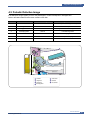
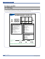
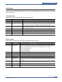
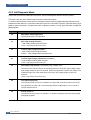
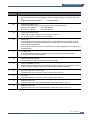
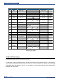
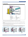
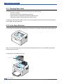
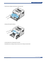
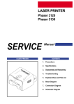
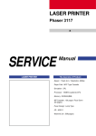
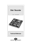
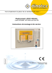
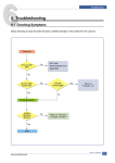
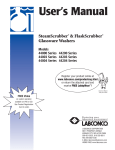
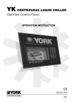
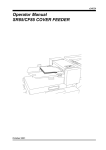
Alignment and Adjustments
4
4. Alignment and Adjustments
4.1 Sample Pattern
This product has the several sample patterns for maintenance. With the sample patterns, check the
existence of the abnormality. The patterns help to regularly maintain the product.
4.1.1 Printing a Demo Page
Print a demo page or a configuration sheet to make sure that the printer is operating correctly.
1) Hold down the Cancel button for about 2 seconds to print a demo page.
2) The Demo page or the configuration sheet shows the printer’s current configuration.
Service Manual
Samsung Electronics
4-1
Alignment and Adjustments
4.2 Control Panel
4.2.1 OP Panel
4.2.2 On Line/Error and Toner Save LEDs
LED
Description
If the On Line/Error lights green, the printer is ready to print.
If the On Line/Error lights red, the printer is experiencing an error,
such as jammed paper, no paper, the open cover or the empty toner cartridge.
If you press the Cancel button while the printer is receiving data,
the On Line/Error LED blinks red to cancel printing.
In Manual Feed mode, if there is no paper in the tray, the OnLine/Error LED blinks red.
Load paper into the tray and the LED stops blinking.
If the printer is receiving data, the On Line/Error LED slowly blinks green.
If the printer is printing the received data, the On Line/Error LED blinks green fast.
If you press the Cancel button in Ready mode, this LED is on and the Toner Save
mode is enabled.
If you press this button once again, this LED is off and the
Toner Save mode is disabled.
If the On Line/Error and Toner Save LEDs blink, your system has some problems.
4-2
Service Manual
Samsung Electronics
Alignment and Adjustments
4.2.3 Cancel button
LED
Description
Printing demo page
In Ready mode, press and hold this button for about 2 seconds until
all LEDs blink slowly, and release.
Manual feeding
Press this button each time you load a sheet of paper in the
tray, when you select Manual Feed for Source from your software application.
Canceling print job
Press this button during printing. The On Line/Error LED blinks while the
print job is cleared from both the printer and the computer, and then return to
Ready mode. This may take some time depending on the size of the print job.
In Manual Feed mode, you can’t cancel the print job by pressing this button.
Toner Save mode on/off
In Ready mode, press this button to turn the Toner Save mode on or off.
Service Manual
Samsung Electronics
4-3
Alignment and Adjustments
4.3 Consumables and Replacement Parts
The cycle period outlined below is a general guideline for maintenance.
The example list is for an average usage of 50 transmitted and received documents per day.
Environmental conditions and actual use will vary these factors.
The cycle period given below is for reference only.
COMPONENT
REPLACEMENT CYCLE
Pick-up Roller
50,000 Pages
Transfer Roller
50,000 Pages
Fuser
50,000 Pages
Toner Cartridge
2,000 Pages(Sales), 1,000 Pages(Initial)
4.4 LED Status Error Message
ERROR
Open Fuser Error
LED Status
The [Error] LED (red) and the [Toner Save] LED are simultaneously
DCU CODE
60
flashing every one-second.
Over Heat Error
The [Error] LED (orange) and the [Toner Save] LED are
68
simultaneously flashing every one-second.
Low Heat Error
The [Error] LED (red) and the [Toner Save] LED are simultaneously
62
flashing every 4 seconds.
4-4
LSU not Ready Error
The [Error] LED (green) and the [Toner Save] LED are
(Pmotor Error)
simultaneously flashing every one-second.
LSU Not Ready Error
The printing is stop in the fad status, and the [Error] LED (green) and
(HSYNC Error)
the [Toner Save] LED are simultaneously flashing every 4 seconds.
95
96
Service Manual
Samsung Electronics
Alignment and Adjustments
4.5 Periodic Defective Image
If the delinquent image regularly occurs in the printed-paper, it is due to delinquent or damaged roller.
Refer to the table in below and check the condition of the roller.
No
Roller
Defective image
Typical defect
1
OPC Drum
75.5mm
white spot on black image or black spot
2
Charge Roller
37.7mm
black spot
3
Supply Roller
47.5mm
light or dark horizontal image band
4
Developing Roller
35.2mm
horizontal image band
5
Transfer Roller
46.2mm
image ghost
6
Heat Roller
63.9mm
Black spot and image ghost
7
Pressure Roller
75.4mm
black spot on the backside
BIN PATH
1
2
3
4
OPC Drum
Charge Roller
Supply Roller
5
6
7
Transfer Roller
Heat Roller
Pressure Roller
Developing Roller
Service Manual
Samsung Electronics
4-5
Alignment and Adjustments
4.6 How to use DCU
4.6.1 DCU Setup
You can examine the malfunction of the printer. To perform DCU, open the front discharge cover and leave the
connect the harness wire(10 pin/4 pin) to the CN1(ML-1610) of the Main control board.
ML SERIES DIAGNOSTIC CONTROL UNIT
04 DEV 300
DEV 350
DEV 350
05 LSU READY
LSU MT & LD
LSU MOTOR
07 PAPER EMPTY
PAPER WIDTH
NEW CRU
SELF
08
EXIT SENSOR
FEED SENSOR
TEST
09 COVER OPEN
STATUS
10 COER HEATING PRINTING TEMP READY HEAT
DIAGNOSTIC
OFF
ON
DIAGNOSTIC CODE
00
01
02
03
04
05
06
07
08
09
10
11
MAIN MOTOR OPERATING SYSTEM
MAIN HIGH-VOLTAGE ON
TRNSFER HIGH-VOLTAGE (-)ON
THV(+) REFERANCE VOLTAGE
DEV/SUPPLY HIGH-VOLTAGE ON/PTL ON
LSU OPERATING SYSTEM
PICKUP CLUTCH ON
PEEMPTY/PWITH/NEW CRU TEST
FEED & EXIT SENSOR TEST
COVER OPEN SENSOR TEST
FUSER TEST
HOT BURN TEST
12
CLEAN MODE PRINT
13
THV(+)TRIGGER, ALL HV & FAN ON
14
THV(+) REFERENCE ON
STATUS CODE
61
WARM UP
00
01
02
03
04
READY
READY
READY
READY
READY
20
30
40
50
PRINT START
FEED SENSOR ON
FEED SENSOR OFF
PAPER OUT
69
SLEEP MODE
(REGAL)
(LETTER)
(A4)
(EXECUTIVE)
(B5)
ERROR STATUS CODE
60
62
68
64
70
71
72
73
95
DIAGNOSTIC
MODE
DOWN
UP
OPEN FUSER ERROR
LOW TEMPERATURE ERROR
OVER HEATING ERROR
COVER OPEN ERROR
NO PAPERR
PAPER JAM 0
PAPER JAM 1
PAPER JAM 2
LSU NOT READY
SHIFT
STOP
ENTER
TO ENTER DIAGNOSTIC MODE, PUSH THREE BUTTONS SIMUL ANEOUSL
AND TURN THE PRINTER POWER ON.
4-6
Service Manual
Samsung Electronics
Alignment and Adjustments
4.6.2 Code
Connect DCU to the printer and turn the power on. It show 7 Segment FND on the panel and each code tells the
function of the printer.
1) Normal Code
While printing or warming up, it indicate the position of the paper
Code
State
61
00~05
Warm up
Ready(kind of paper)
20, 21, 22
Print Start
30
40
50
69
Feed Sensor On
Feed Sensor off
Paper Out
Sleep Mode
Description
The printer is on, the cover is open or close.
The printer is ready, the paper is detected when the first paper is printed.
00: Legal ,01: Letter ,02: A4 ,03: EXEC ,04: B5 ,05: Folio, 06: A5/A6
The engine controller received the print order from the video controller.
20: 1st, 21: MP, 22: SCF
The paper is passing out of the Feed Sensor.
The paper has passed out of the Feed Sensor.
The paper has passed out of Exit Sensor.
The fuser power turned off to minimize the power consumption.
2) Error Code
When detecting the malfunction, the printing is stopped to indicate error code.
Code
State
60, 62, 68
Fuser Error
64
65
70
71
72
Cover Open
CRU Error
No Paper
Paper Jam 0
Paper Jam 1
73
Paper Jam 2
76
95
Out Bin Full
LSU Not Ready
Description
The error in the fuser occurred. There is a short circuit in the thermistor
and the thermostat while printing, Low Temperature Error occurs.
• 60: Open Fuser Error
• 62: Low Heat Error
• 68: Over Heat Error
The Printer Cover is open.
The Toner Cartridge not installed,
No paper in the paper cassette.
The front part of paper is jammed between pickup unit and Feed sensor.
The front part of paper is jammed between the Discharge sensor and Feed
sensor.
The front part of paper is jammed just after passing through the discharge
sensor.
The Out bin is filled with paper.
LSU Scanner Motor not ready or Hsync signal not output.
Service Manual
Samsung Electronics
4-7
Alignment and Adjustments
4.6.3 Self Diagnostic Mode
If Error code occurs due to malfunction of the printer, perform Self Diagnostic Mode to solve the problem.
The printer works only in the self-test mode to solve the malfunction problem.
To enter the self-test mode, turn the power on pressing the buttons of [Down], [Shift] and [Stop] at the same time.
Release the button within 2 or 3 seconds if 78 shows in the DCU. If 00 shows in the DCU, press the button [Up] or
[Shift] to select the self+test , and press the button of [Enter] to operate. To stop, press the button of [shift] and
[Enter] together.
Code
Description
00
Main Motor Operating System
Only the main motor is in operation.
01
Main High Voltage On(THV-)
-1400 voltage output by MHV terminal.
Caution : High voltage probe should be used.
02
Transfer High Voltage(-)On(THV-)
-1000 voltage output by MHV terminal.
Caution : High voltage probe should be used.
03
Transfer High Voltage (+)Reference on (THV +)
+1300 voltage output by MHV terminal.
Caution : High voltage probe should be used.
04
DEV/supply High Voltage : DEV/Supply High Voltage Test.
The left one of the three LEDs in the self-test panel is on when DEV high voltage Supply
high voltage output by each HV terminal. Press the [Up] button to switch the voltage. The
middle and right one of the three LEDs are on and -350 voltage output by DEV HV
terminal.
Caution : High voltage probe should be used.
4-8
05
LSU Operating System
The scanning motor of LSU is in operation, the right LED of the three buttons on. Press
the [Up] button to Check LD. LD is functioning and the middle button is on. If the LD is
normal, all LEDs are on.
06
Pickup clutch on
The Solenoid in the printer is in operation. To stop the operation, Press the button [shift]
and [Enter] together.
Service Manual
Samsung Electronics
Alignment and Adjustments
Code
Description
07
Paper Empty Sensor Test :
If activate the Actuator of the PEMPTY Sensor, the left and right of the three LEDs are
on.
Paper Empty Sensor ON/OFF
1st LED ON/OFF
08
Feed & Exit Sensor Test
Test the Feed sensor and Discharge sensor in the same way as '07'.
Feed Sensor ON/OFF
2nd LED ON/OFF
Exit Sensor ON/OFF
3rd LED ON/OFF
09
Cover Open Sensor Test
Test the Cover Open Sensor in th same way as code '07’
Cover Open Sensor ON/OFF1st LED ON/OFF
10
Fuser Test
If the [Enter] button pressed, the right LED is on and temperature of the fuser is up to
READY Mode. If the [Up] button pressed, the middle LED is on and temperature of the
fuser is up to Printing Mode.
If you press the button once more, the left LED is on and temperature of the fuser is up to
overheat Mode.
11
Hot Burn Test
If the [enter] button pressed, the printer is continuously printing without detection.
Turn the power off to stop operation.
12
Cleaning Mode Print Mode
Print the paper to clean the OPC Drum in the Cartridge.
13
THV(+) TRIGGER. ALL HV :
All high voltage output by each HV terminal and LSU and the fan is in operation. In this
mode, electronic resistance of transfer roller and high voltage is detected.
14
PTL Test : (ML-1610 : not design)
Indicates the function of the PTL, same method of the code ‘07’.
15
Fan Test :
Indicates the function of the Fan, same method of the code ‘07’.
16
Manual Pickup Test :
Indicates the function of th Manual Pickup, same method of the code ‘07’.
17
Manual Sensor Test :
Indicates the function of the Manual Sensor, same method of the code ‘07’.
Service Manual
Samsung Electronics
4-9
Alignment and Adjustments
No.
Function
Enter
00
Motor
Motor Run
Motor Stop
01
MHV
Mhv On
Mhv Off
-1300V
02
THV(-)
Thv Negative On
Thv Negative Off
-1000V
03
THV(+)
Thv On
Thv Off
+1300V
04
DEV
Dev On
Dev Off
-350V
05
LSU
LSU Run
LSU Stop
020mV
06
Pic kUp
Pickup On
07
PEmpty
08
Sensor
09
Cover
10
Fus er
Fuser On
11
HotBur n
HotBurn On
12
Clean Print
Clean Printing
13
Stop
Supply
DEV
0 : -550V
0 : -350V
On
Off
Ready
Remar k
Pickup Off
Paper Empty
Ex it
Feed
Cover Open
Fuser Off
Thv
low
Refer ence
14
15
16
Up/Down
adequate
high
PTL 없음
PTL
PTL On
P TL Off
FAN
Fan On
Fan Off
Manual Pickup On
Manual Pickup Off
Manual
Pic kUp
Manual
17
Sensor
Manual Sensor
4.6.4 Self Test Button
If the Self-Test button pressed, vertical lines are printed.
Turn the power on while pressing this button, '89' shows in the DCU and the printer is warming up. After warmingup the printer is in READY Mode, and '88' shows in the DCU. In this mode, without any detection, the printer begins
printing(trial printing and data from the PC). It is convenient to use this mode when the engine malfunction is
detected in the control board.
4-10
Service Manual
Samsung Electronics
Alignment and Adjustments
4.7 Paper Path
BIN PATH
❶ SMPS
❷ Fuser
❸ Toner Cartridge
❹ LSU
❺ Exit Roller
❻ OPC
❼ Pick-Up Roller
❽ KNOCK-UP PLATE
❾ KNOCK-UP PLATE DOWN
❿ ASS’Y HOLDER PAD
Feed Sensor
MAIN PBA
SMPS
HVPS
1) After taking order, the printer feeds the printing paper from the cassette or manual feeder.
2) The fad paper passes the paper feeding sensor. (Jam 0 occurs if the sensor is not operated after certain time
passes)
3) The paper passed the paper feeding sensor moves to the paper exit sensor via printing process. (Jam 1 occurs
if the sensor is not operated after certain time passes)
4) The paper passed the paper exit sensor moves out from the set. (Jam 2 occurs sometime after if the tailing edge
of the paper is not coming out from the set after the leading edge of paper passes the paper exit sensor.)
BIN PATH
BIN PATH
BIN PATH
Service Manual
Samsung Electronics
4-11
Alignment and Adjustments
4.7.1 Clearing Paper Jams
Occasionally, paper can be jammed during a print job. Some of causes include:
• The tray is overfilled.
• The front cover has been opened during a print job.
• Paper that does not meet paper specifications has been used.
• Paper that is outside of the supported size range has been
If a paper jam occurs, the On Line/Error LED on the control panel lights red. Find and remove the jammed paper.
If it is invisible, look inside the printer.
4.7.2 In the Paper Exit Area
1. If the paper jams as it exits to the output tray and a long portion of the paper is visible, pull the paper straight out.
When you pull the jammed paper, if there is resistance and the paper does not move immediately, stop pulling.
Continue with the next step.
2. Open the top cover and the inner cover.
H eat roller
4-12
Service Manual
Samsung Electronics
Alignment and Adjustments
3. Loosen the paper if it is caught in the heat rollers. Then pull the paper gently out.
4. Close the inner cover and the top cover.
5. Open and close the front cover. Printing can be resumed.
Service Manual
Samsung Electronics
4-13
Alignment and Adjustments
4.7.3 In the Paper Feed Area
1. Remove any missfeed paper by pulling it out by the visible edge from the tray. Make sure that all of the paper is
properly aligned in the tray.
2. Open and close the front cover. Printing can be resumed.
4.7.4 Around the Toner Cartridge
1. Open the front cover.
4-14
Service Manual
Samsung Electronics
Alignment and Adjustments
2. Pull the toner cartridge out and remove it from the printer.
3. Gently pull the paper toward you.
4. Check that there is no other paper in the printer.
5. Reinstall the toner cartridge, and then close the cover. Printing can be resumed.
Service Manual
Samsung Electronics
4-15
Alignment and Adjustments
4.7.5 Tips for Avoiding Paper Jams
By selecting the correct paper types, most paper jams can be avoided.
• Ensure that the adjustable guides are positioned correctly.
• Do not overload the tray.
• Do not remove the paper from the tray while printing.
• Flex, fan and straighten the paper before loading.
• Do not use creased, damp or highly curled paper.
• Do not mix paper types in the input tray.
• Use only recommended print media.
• Ensure that the recommended print side is facing up when loading paper into the input tray.
4.7.6 Solving Print Quality Problems
Print Quality Checklist
Print quality problems can be resolved by following the checklist below.
• Redistribute toner in the toner cartridge
• Clean the inside of the printer
• Adjust the print resolution from the printer properties
• Ensure that the Toner Save mode is off
• Clear general printing problems
• Install a new toner cartridge, and check the print quality
4-16
Service Manual
Samsung Electronics