1
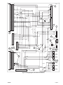
-J05408
REV. 2011-07-01
BOOM!™ AUDIO CUSTOM TOURING SYSTEM
Even if this kit is not being installed by a Harley-Davidson
dealer, this special equalization software is available without
charge from any dealer through Digital Technician II. Dealer
labor rates may apply for the upgrade procedure.
GENERAL
Kit Number
76000209
Models
For model fitment information, see the P&A retail catalog or
the Parts and Accessories section of www.harley-davidson.com
(English only).
NOTE
The amplifiers and speakers in this kit are part of a system that
has an impedance of one Ohm, and are for use ONLY with the
Boom!™ Audio Custom Touring System and Harmon/Kardon®
AM/FM/CD radio on select fitments. See the P&A retail catalog
or the Parts and Accessories section of www.harley-davidson.com (English only).
Using these speakers on 2005 or earlier Harley-Davidson audio
systems WILL cause permanent damage to those systems.
Additional Parts and Supplies Required
Proper installation of this kit requires separate purchase and
installation of Harley-Davidson VENTED fairing lowers (or
replacement if the vehicle currently has NON-VENTED lowers).
See the P&A retail catalog or the Parts and Accessories section
of www.harley-davidson.com (English only).
Replacement of saddlebag lids is required. See Table 1.
These items are available from a Harley-Davidson dealer.
Table 1. Saddlebag Lids With Speaker Mount
Part No.
Description
90200612
Lid kit (left, unfinished)
90200613
Lid kit (right, unfinished)
90200614
Lid kit (left, Vivid Black)
90200615
Lid kit (right, Vivid Black)
Loctite® 243 Medium Strength Threadlocker and Sealant - Blue
(Part No. 99642-97) and RTV sealant are required for proper
installation of this kit.
If the vehicle is CURRENTLY EQUIPPED with fairing
lowers, two rubber washers (Part No. 7415A) will be needed.
NOTE
The purchase of this kit entitles you to a specially developed
sound equalization software that is used in conjunction with
the Advanced Audio system. This unique equalization was
designed to optimize the performance and sound response of
the Boom!™ Audio speakers.
-J05408
The rider's safety depends upon the correct installation
of this kit. Use the appropriate service manual procedures.
If the procedure is not within your capabilities or you do
not have the correct tools, have a Harley-Davidson dealer
perform the installation. Improper installation of this kit
could result in death or serious injury. (00333a)
NOTE
This instruction sheet refers to service manual information. A
service manual for this year/model motorcycle is required for
this installation. In addition, a model year 2012 or later FLHXSE
service manual supplement is recommended. Both are available from a Harley-Davidson dealer.
Electrical Overload
It is possible to overload your vehicle's charging system
by adding too many electrical accessories. If the combined
electrical accessories operating at any one time consume
more electrical current than the vehicle's charging system
can produce, the electrical consumption can discharge
the battery and cause damage to the vehicle's electrical
system. See an authorized Harley-Davidson dealer for
advice about the amount of current consumed by additional electrical accessories or for necessary wiring
changes. (00211c)
When installing any electrical accessory, be certain not
to exceed the maximum amperage rating of the fuse or
circuit breaker protecting the affected circuit being modified. Exceeding the maximum amperage can lead to electrical failures, which could result in death or serious injury.
(00310a)
The Boom!™ Audio Custom Touring System requires up to 16
Amps of additional current from the electrical system.
Kit Contents
See Figure 9, Figure 10, Table 3, Figure 11 and Table 4 for
front-of vehicle components.
See Figure 12, Table 5 and Table 6 for rear-of vehicle components.
1 of 15
PREPARATION
FAIRING SPEAKER INSTALLATION
NOTE
For 2007 and later vehicles equipped with security siren:
•
Verify that the Hands-Free Fob is present.
•
Turn the ignition key switch to IGNITION.
To prevent spray of fuel, purge system of high-pressure
fuel before supply line is disconnected. Gasoline is
extremely flammable and highly explosive, which could
result in death or serious injury. (00275a)
1.
Follow service manual instructions to purge the fuel supply
of high pressure gasoline and remove the fuel supply line.
Remove and Replace Upper Fairing Speakers
1.
NOTE
Do not connect the vehicle harness to the speaker spade
contacts at this time.
2.
Remove and Relocate Auxiliary Gauges
NOTES
To prevent accidental vehicle start-up, which could cause
death or serious injury, remove main fuse before proceeding. (00251b)
Refer to the service manual and follow instructions to
remove the main fuse.
3.
Remove the seat. Retain all seat mounting hardware.
•
Electrical connectors are identified in the service manual
by the numbers and letters shown here within brackets.
1.
If no lower gauges: Remove the plastic plugs from the
lower holes in the inner fairing.
With lower gauges: See Figure 9. Disconnect the oil
pressure gauge [113] and lamp [112] connectors. Remove
two hex nuts (D) and the back clamp (C), and remove the
gauge (B) from the right lower opening in the inner fairing.
For 2006 and 2007 models: See the service manual for
battery removal instructions.
For 2008 and later models: Refer to the service manual
and follow the instructions to remove the ECM caddy from
the top of the battery. Disconnect the battery cables,
negative (-) cable first.
When servicing the fuel system, do not smoke or allow
open flame or sparks in the vicinity. Gasoline is extremely
flammable and highly explosive, which could result in
death or serious injury. (00330a)
5.
For ALL models: Follow the instructions in the service
manual to remove the instrument console (if equipped)
from the fuel tank.
6.
See the service manual for fuel tank removal instructions.
7.
Release the catches on the wire trough cover and remove
the cover.
NOTE
Models WITHOUT fairing lowers or models with NON-VENTED
fairing lowers will require separate purchase of VENTED
lowers.
8.
Models Equipped With Fairing Lowers: Remove the
lower fairings per service manual instructions. Discard the
rubber washers at the bottom of the fairings.
9.
ALL Models: Follow service manual instructions to remove
the outer fairing and windshield.
-J05408
The following sections describe the suggested arrangement; Removal of the air temperature and oil pressure
gauges (if present) from the vehicle, relocation of the fuel
gauge and volt meter to the lower positions, and installation of new tweeters in the two upper auxiliary gauge
positions.
However, the tweeters and any two of the four gauges
can be installed into any position as desired.
Disconnect negative (-) battery cable first. If positive (+)
cable should contact ground with negative (-) cable connected, the resulting sparks can cause a battery explosion,
which could result in death or serious injury. (00049a)
4.
See Figure 9. Follow the service manual and use the new
screws (2) from the kit to install the new 5.25-inch (133
mm) diameter speakers (1) into the inner fairing.
Tighten the screws to 16-18 in-lbs (1.8-2.0 Nm).
•
2.
Remove the original equipment (OE) speakers from the
inner fairing per service manual instructions.
Disconnect the air temperature gauge [115] and lamp [114]
connectors and remove the gauge (A) in the same manner.
2.
ALL versions: Disconnect the fuel gauge [117] and lamp
[116] connectors. Remove two nuts and the back clamp,
and remove the fuel gauge (A) from the left upper opening
in the inner fairing.
3.
Install the fuel gauge into the left lower opening. Slide the
back clamp over the gauge studs. Verify that the tab on
the back clamp engages the slot at the bottom of the inner
fairing bore.
4.
Loosely install the hex nuts on the studs. Verify that the
gauge is properly aligned, then tighten the nuts to 10-20
in-lbs (1.2-2.2 Nm). Connect the fuel gauge [117] and
lamp [116] connectors.
5.
Disconnect the voltmeter gauge [111] and lamp [110]
connectors (6), and reposition the voltmeter (B) to the right
lower opening in the same manner.
Install Fairing Tweeters
1.
See Figure 9. Get two tweeters (3) from the kit, and the
two back clamps (C) and four hex nuts (D) from the gauges
removed from the vehicle.
For vehicles that only had TWO auxiliary gauges, two
additional back clamps (Part No. 67352-96A) and four
additional hex nuts (Part No. 67043-96) will be needed.
2.
Install the tweeters into the left and right upper openings
in the inner fairing. Slide the back clamp over the tweeter
2 of 15
studs. Verify that the tab on the back clamp engages the
slot at the bottom of the inner fairing bore.
3.
is06876
8
4
5
3
1
Install the hex nuts on the studs, and tighten to 10-20 inlbs (1.2-2.2 Nm).
7
Install Fairing Amplifier and Modules
NOTES
•
•
If another module has been installed on top of the radio
on the brake-lever side, relocate that module to the clutchlever side of the radio per the instructions supplied with
that module.
6
2
If another module has been installed on top of the radio
on the clutch-lever side, relocate that module per the
instructions supplied with that module.
An iPod module installed on top of the radio on the clutchlever side can be relocated to the right-side saddlebag as
described later in these instructions.
is07006
1.
2.
3.
4.
5.
6.
7.
8.
1
2
Figure 2. Inner Fairing Connectors (FLHX, FLHT/C/U)
2.
See Figure 11. Get the audio harness (10) from the kit.
3.
If there is currently a harness connected to the six-way
vehicle interconnect harness socket housing [6B] and the
35-way receptacle [28A] on the back of the radio, disconnect and remove that harness from the vehicle.
3
See Figure 3 and Table 2, Item 1. Plug the black six-way
audio harness pin housing [6A] (labeled "CONNECTOR
6") from the new audio harness into the vehicle interconnect harness socket housing [6B].
1. Amplifier
2. Radio case screw
3. Rubber grommet (2)
Figure 1. Front Amplifier Installation
1.
See Figure 1. Remove the screw (2) at the back of the
radio.
2.
Position the amplifier (1) on top of the AM-FM radio case,
with the metal cones on one end fitting firmly into the leftmost (brake-lever side) rubber grommets (3) at the front
of the radio.
Audio to interconnect harness connector [6]
Main to interconnect harness connector [2]
Left-side fairing bracket
Right-side fairing bracket
Audio or radio harness connector
35-way connector on back of radio
Left-side front speaker
Right-side front speaker
NOTE
Six additional branches of the audio harness exit from the same
end of the large conduit (see Figure 11):
•
Eighteen inch (45.7 cm) long, labeled "L. FAIRING SPKR
(35F)", with two-way female Delphi connector [35FB] (Item
2) for left fairing speaker.
•
Thirteen inch (33.0 cm) long, labeled "L.TWEETER (35T)",
with two-way female Delphi connector [35TB] (Item 4) for
left tweeter.
•
Sixteen inch (40.6 cm) long, labeled "L. LWR (35L)", with
two-way Amp socket housing [35LB] (Item 6) for left lower
speaker.
See Figure 2. Make note of the location of the black six-way
Deutsch audio to interconnect harness connector [6] (Item 1)
before moving the gray Molex 12-way connector [2] (Item 2).
•
Four inch (10.2 cm) long, labeled "AMP (149)", with 16way Molex socket housing [149B] (Item 8) for front amplifier.
1.
•
Nine inch (22.9 cm) long, labeled "IPOD (274F)", with
eight-way Deutsch socket housing [274F] (Item 13) for
optional iPod module.
•
Fifty inch (1.27 M) long, to rear of vehicle.
3.
Fasten the amplifier to the radio with the radio case screw
(2). Tighten to 35-45 in-lbs (4.0-5.1 Nm).
Harness Installation and Routing
NOTE
Remove the gray Molex 12-way main to interconnect
harness connector [2] from the left-side (clutch lever side)
fairing bracket (radio support bracket, Item 3).
-J05408
3 of 15
4.
See Figure 3 and Table 2. Plug the two-way connector
[35FB] (2) into the left fairing speaker. Plug the two-way
connector [35TB] (4) into the left tweeter.
5.
Plug the 16-way Molex socket housing [149B] (8) into the
front amplifier.
NOTE
The optional iPod module can be mounted either in the front
fairing or right-side saddlebag.
6.
At the opposite end of the large conduit, plug the 35-way
Amp (Tyco) socket housing [28B] (Item 9) into the open
receptacle on the back of the radio.
11. If an iPod module is mounted in the front fairing, plug
the eight-way Deutsch socket housing [274F] (Item 13)
into the iPod module.
7.
Unplug the 23-way Amp socket housing [27B] (Item 10)
from the back of the radio. Open the secondary lock per
instructions in the service manual appendix. Insert the four
terminated wires (11) coming from the large conduit into
the empty cavities of the socket housing as follows:
12. Route the left lower speaker branch of the audio harness
(6, with white/orange and light green/white wires) down
along the left side of the steering head to the left center
of the engine guard.
•
Light green/black wire into cavity 1.
•
White/orange wire into cavity 16.
•
Light green/white wire into cavity 17.
•
Gray/red wire into cavity 18.
8.
Close the secondary lock per instructions in the service
manual appendix, and plug the socket housing back into
the receptacle on the back of the radio.
NOTE
Four additional branches of the audio harness exit from the
same end of the large conduit (see Figure 11):
10. If equipped, plug the twelve-way Deutsch socket housing
[185X] (Item 12) into the XM satellite radio module.
Route the right lower branch (7, with gray/red and light
green/black wires) down along the right side of the steering
head to the right center of the engine guard.
NOTE
Position connectors [34LB] and [35LB] outside the upper fairing
to allow easy disconnection when removing fairing lowers.
13. Use cable straps from the kit to fasten the upper section
of the audio harness to nearby wiring inside the fairing.
14. Route the long branch of the audio harness along the
clutch-lever side of the radio and rearward, through the
openings in the wire caddy alongside other harnesses
down the vehicle backbone. Use cable straps to fasten to
other harnesses in the caddy.
•
Eighteen inch (45.7 cm) long, labeled "R. FAIRING SPKR
(34F)", with two-way female Delphi connector [34FB] (Item
3) for right fairing speaker.
•
Thirteen inch (33.0 cm) long, labeled "R. TWEETER
(34T)", with two-way female Delphi connector [34TB] (Item
5) for right tweeter.
Be sure that steering is smooth and free without interference. Interference with steering could result in loss of
vehicle control and death or serious injury. (00371a)
•
Sixteen inch (40.6 cm) long, labeled "R. LWR (34L)", with
two-way Amp socket housing [34LB] (Item 7) for right lower
speaker.
•
•
Eight inch (20.3 cm) long, labeled "XM (185X)", with
twelve-way Deutsch socket housing [185X] (Item 12) for
optional XM satellite radio module.
9.
Plug the two-way connector [34FB] (3) into the right fairing
speaker. Plug the two-way connector [34TB] (5) into the
right tweeter.
-J05408
Be sure wires do not pull tight when handlebars are
turned fully to left or right fork stops.
15. Route the harness along the right side of the battery cavity.
Bring the red fuse holder [43] (Item 14), black ground wire
(15) and black/green ground wire (16) into the front of the
battery compartment.
Position the four-way P&A connector [4B] (Item 17) and
B+ connector (18) in the area under the seat.
16. Route the two long branches rearward to the front of the
rear fender. Use a cable strap to fasten both branches to
the frame.
4 of 15
1
2
3
4
5
6
7
8
9
10
11
12
13
14
15
16
17
18
19
20
21
22
23
24
25
26
27
28
29
30
31
32
33
34
35
is07007
GN
1
2
3
4
5
6
7
8
9
10
11
12
13
14
15
16
17
18
19
20
21
22
23
24
25
26
27
28
29
30
31
32
33
34
35
[289B]
BN
Y/V
12
11
Y/O
W
GN
TN/R
Y/O
Y/O
Y/V
LGN/BN
7
BK/GN
SPL-1
Y/O
6
5
4
R/O
Y/V
V/GY
TN/R
SPL-2
Y/V
SPL-13
TN/R
BK
V/GY
3
2
1
TN/BK
BK/GN
15
SPL-14
V/GY
GR-1
LGN/BN
BK
12
11
10
9
GN
LGN/BN
W/BN
8
7
LGN/BN
6
5
4
GN
W/BN
BN
O/BE
R
R
SPL-12
TN/BK
TN/BK
Y/O
Y/V
19
1
3
2
1
[288B]
[28B]
9
12
11
10
9
8
7
17
SPL-11
R/O
BK
W
SPL-7
R
O/BE
8
7
6
5
4
3
2
13
10 12
1
[4B]
O/BE
1
2
3
4
18
Y/V
[B+]
Y/O
SPL-10
SPL-3
BK/GN
BK/GN
BK/GN
R/O
V/GY
TN/R
R
[43B]
R
SPL-4
R
16
TN/BK
[274F]
14
2
GR-2
R
[27B]
1
2
3
4
5
6
7
8
9
10
11
12
13
14
15
16
17
18
19
20
21
22
23
6
5
4
3
2
1
Y/O
R/O
BK/GN
R/O
[185X]
1
2
3
4
5
6
7
8
9
10
11
12
13
14
15
16
17
18
19
20
21
22
23
[6A]
BK/GN
Y/V
Y/V
Y/O
6
5
4
3
2
1
20
10
9
8
LGN/W
O/BE
BK/GN
R
LGN/BK
W/O
4
1
2
6
2
1
[35FB]
2
1
[35TB]
2
1
[35LB]
LGN/W
11
W/O
LGN/W
LGN/W
SPL-9
LGN/W
W/O
W/O
SPL-8
W/O
3
LGN/BK
W/O
LGN/W
GY/R
BK/GN
LGN/BK
R
R
BK/GN
LGN/BK
GY/R
SPL-6
LGN/BK
GY/R
1615 1413121110 9 8 7 6 5 4 3 2 1
GY/R
[149B]
8
SPL-5
GY/R
LGN/BK
GY/R
5
7
2
1
[34FB]
2
1
[34TB]
2
1
[34LB]
Figure 3. Wiring Diagram, Audio Harness 69200321
-J05408
5 of 15
Table 2. Wiring Diagram, Audio Harness 69200321
Item
Description
1.
Six-way pin housing [6A] to interconnect harness (labeled "CONNECTOR 6")
2.
Two-way female Delphi connector [35FB] to left fairing speaker, labeled "L. FAIRING SPKR (35F)
3.
Two-way female Delphi connector [34FB] to right fairing speaker, labeled "R. FAIRING SPKR (34F)"
4.
Two-way female Delphi connector [35TB] to left tweeter, labeled "L. TWEETER (35T)"
5.
Two-way female Delphi connector [34TB] to right tweeter, labeled "R. TWEETER (34T)"
6.
Two-way Amp socket housing [35LB] for left lower speaker, labeled "L. LWR (35L)"
7.
Two-way Amp socket housing [34LB] for right lower speaker, labeled "R. LWR (34L)"
8.
16-way Molex socket housing [149B] for front amplifier, labeled "AMP (149)"
9.
35-way socket housing [28B] to back of radio
10.
23-way Amp socket housing [27B] to back of radio
11.
Four terminated wires from large conduit
12.
Twelve-way Deutsch socket housing [185X] for XM satellite radio module, labeled "XM (185X)"
13.
Eight-way Deutsch socket housing [274F] for iPod module, labeled "IPOD (274F)"
14.
Red amplifier fuse wire [43B]
15.
Black ground ring terminal
16.
Black/green ground ring terminal
17.
Four-way P&A accessory connector [4B], labeled "ACCY CONNECTOR 4"
18.
B+ connector, labeled "B+ (160)"
19.
Left saddlebag connector [288B], labeled "LH S'BAG (288)"
20.
Right saddlebag connector [289B], labeled "RH S'BAG (289)"
Modify and Install Vented Fairing Lowers
1.
See Figure 10. Disassemble the vented fairing lowers per
service manual instructions with the following exceptions:
a.
b.
c.
2.
is07095
1
2
Remove the glove box, door and tether (F) from the
lower fairing (E) per the disassembly instructions in
the service manual. Keep the screws (J).
3
Remove the vent door (H) from the glove box, making
note of the order and orientation of the attaching parts.
4
Install the vent door onto the new speaker housing
(4) from this kit with the attaching parts in the same
order and orientation as just removed. Tighten the
locknut (I) per service manual instructions.
1.
2.
3.
4.
See Figure 4. In the upper part of the fairing (1), measure
about 1.0 in (25 mm) over (2) and 0.5 in (12 mm) up (3)
from the lower fairing cap mating flange (shaded area),
and drill a 3/8 in (9.5 mm) hole (4) in the glove box inboard
side wall.
Lower fairing (left side shown)
Measure one in (25 mm) over
Measure 1/2 in (12 mm) up
Drill 3/8 in (9.5 mm) hole
Figure 4. Drill Speaker Wire Hole in Lower Fairing
See Figure 10. Install a grommet (8) into the hole.
6.
Route the speaker harness wires through the large
opening in the face of the speaker housing.
3.
From the outside, route the terminated wires of a fairing
lower speaker harness (6) through the grommet.
7.
4.
Place the lower fairing per service manual instructions,
using a new rubber washer (K, Part No. 7415A) at the
bottom attachment point to the engine guard.
Get a two-way pin housing (7) from the kit. Insert the
red/orange wire and terminal into cavity 1 of the pin
housing per instructions in the service manual appendix.
Insert the light green wire and terminal into cavity 2.
5.
Position the fairing cap (G) against the lower fairing, align
and install the lower fairing per service manual instructions.
-J05408
Plug the pin housing into the back of the speaker.
8.
Secure the speaker housing to the lower fairing with the
three screws (J) removed earlier with the glove box, door
6 of 15
and tether. Tighten the screws to 20-25 in-lbs (2.3-2.8
Nm).
9.
is07096
2
1
Repeat on the opposite side of the vehicle.
SADDLEBAG PREPARATION
Saddlebag Lid Removal
6
3
NOTE
•
Remove all items from the saddlebags.
•
The saddlebags do not have to be removed from the
vehicle to perform the lid removal procedure.
•
Take care to avoid damage to the saddlebag bottom when
removing the lid.
1.
Remove two screws to release the check strap from the
saddlebag lid only.
2.
Remove five screws to release the lid from the saddlebag
latch. The latch can remain attached to the saddlebag
bottom. Retain the screws and backing plate for installation
of the new saddlebag lid. The removed lid can be discarded or set aside.
3.
5
7
10
1.
2.
3.
4.
5.
6.
7.
8.
9.
10.
Saddlebag Drilling
Lay a clean pad or blanket on the work surface to protect
the painted surfaces of the saddlebag.
2.
Remove one saddlebag bottom from the vehicle per service manual instructions. Lay it, outboard side down, on
the protected work surface.
3.
4.
See Figure 5. Lay a strip or strips of masking tape in the
approximate area of the holes to be made in the inboard
saddlebag wall for the saddlebag jumper harness connector.Very carefully measure and mark the hole locations
as shown.
Mark the centers of the two holes with a center punch.
Drill two 9/32 in (7 mm) diameter holes in the saddlebag
wall.
8
9
Repeat for the remaining saddlebag lid.
1.
4
Saddlebag rear mounting hole
Measure 1.31 in (33 mm) rearward
Measure 2.38 in (60 mm) down
Measure 50 degree angle
Measure 2.63 in (67 mm)
Drill 9/32 in (7 mm) hole, (2) places
Measure 0.50 in (12.7 mm)
Measure 1.68 in (42.7 mm)
Measure 1.00 in (25.4 mm)
0.25 in (6.4 mm) radius, (4) places
Figure 5. Cut Connector Holes in Inboard Saddlebag Wall
(Left Bag Shown)
Saddlebag Lid Assembly
NOTE
Unfinished saddlebag lids must be finish painted before
installation.
1.
See Figure 12 and Table 5.
5.
Carefully cut the rectangular hole for the connector body.
Get the gasket (N), mounting plate (O), two wear plates
(M) and the finish painted saddlebag lid (L) from one of
the saddlebag lid kits (purchased separately).
6.
Remove the tape. Lightly sand the hole to remove burrs
and sharp edges. Clean the saddlebag wall surface of
tape residue with a mixture of 50-70% isopropyl alcohol
and 30-50% distilled water. Allow to dry thoroughly.
NOTE
Ambient temperature should be at least 60 °F (16 °C) for
proper adhesion of the wear plates and gasket to the saddlebag
lid.
7.
Set the saddlebag aside, and repeat Steps 1-6 for the
opposite side saddlebag.
2.
See Figure 6. Remove the liner from the adhesive backing
of one of the wear plates (2). Carefully position the wear
plate to the saddlebag lid (1), centering it on the tab (3),
and press firmly into place. Hold the wear plate in position
with steady pressure for about a minute.
Repeat with the second wear plate at the other end of the
lid.
-J05408
7 of 15
is06988
1
1
13. Repeat Steps 1 through 12 for the opposite-side saddlebag
lid.
5
4
3
2
1.
2.
3.
4.
5.
Saddlebag lid
Wear plate (2)
Tab
Gasket
Adhesive backing
Figure 6. Assemble Wear Plates and Gasket to Saddlebag
Lid
3.
•
See Figure 12. Lay the mounting bracket (O) onto the lid
flange, lining up the five mounting holes.
NOTE
Orient the gasket with the tall edge toward the outer lip
of the cover as shown in Figure 6.
•
Begin gasket installation in the center of the inboard side
of the lid, opposite the hinge (see Figure 8, Item 15).
•
Gasket adhesive will hold the mounting plate in place.
4.
Gradually remove the liner from the adhesive backing
(Figure 6, Item 5) of the saddlebag lid gasket (4) as the
gasket is pressed into place around the inside perimeter
of the lid (1) as shown.
5.
Set the lid, gasket side down, on the clean pad or blanket
of the work surface.
6.
See Figure 12. Get a saddlebag speaker assembly (18),
speaker basket (12) and four #8-18 x 1.25 in. (31.8 mm)
long screws (19) from the speaker kit.
7.
From the underside of the saddlebag lid, and with the large
rectangular opening (Q) toward the front, place the speaker
basket under the speaker cavity and snap it into the lid.
8.
Insert a screw, from the top, through each mounting hole
in the speaker. With the tweeter (P) toward the front of the
saddlebag, install the speaker into the cavity at the front
of the saddlebag lid.
9.
Align the four screws with the mounting holes in the
basket, and tighten to 10-15 in-lbs (25.4-38.1 Nm).
10. Get the correct speaker grille (13 or 14), four rubber
washers (20) and four #8-18 x 0.75 in. (19.0 mm) long
screws (21) from the speaker kit.
11. Place a rubber washer into the well surrounding each grille
mounting hole in the lid.
-J05408
12. Place the speaker grille into position over the speaker
face. From the underside of the saddlebag lid, insert the
screws through the holes in the lid and into the mounting
pads in the grille. Tighten the screws to 10-15 in-lbs (25.438.1 Nm).
14. Fasten the new lid to the saddlebag latch and bottom with
the five screws (R) removed earlier. Tighten to 20-25 inlbs (2.3-2.8 Nm).
NOTE
See Figure 7. The saddlebag latch hinge is shown with the
pins removed for clarity.
15. Get two foam pads (Figure 12, Item 24) from the kit. Cut
one piece in half as shown in Figure 7. Remove the liner
from the adhesive backing of the uncut pad and affix to
the flat side of the latch connector segment.
Remove the liner from the adhesive backing of one cut
pad and affix to the hinge side of the latch connector
segment as shown.
NOTE
The remaining foam pad segment can be cut and used as
needed to eliminate any saddlebag vibration induced by
speaker operation.
16. Assemble the remaining saddlebag in the same manner.
is07029
2
5
4
3
1
5
1.
2.
3.
4.
5.
Saddlebag hinge segment
Lid hinge segment
Hinge connector segment
Latch backing plate segment
Foam pad (2)
Figure 7. Install Foam Pads to Saddlebag Latch Hinge (Left
Side Shown)
8 of 15
SADDLEBAG HARNESS INSTALLATION
3.
See Figure 8. Install the plug cover (3) over the panel
mount connector (1) and jumper harness from the inside
of the saddlebag. Insert two screws through the connector
flange and saddlebag wall, and into the threaded holes in
the plug cover. Tighten to 35-40 in-lbs (3.95-4.52 N-m)
4.
Route the harness:
Left Saddlebag Harness
1.
See Figure 12. Get the left-side saddlebag, the correct
saddlebag speaker jumper harness (15), a plug cover (25)
and two screws (26) from the kit.
2.
Feed the jumper harness connectors [149R] and [42S],
from the outside, through the rectangular opening cut in
the saddlebag inboard wall so the 12-way panel mount
connector [288] (Item T) fits into the opening.
15
6
11
is07025
13
14
5
12
1
4
rearward along the inboard wall.
c.
Route the long leg of the harness, with connector
[42S], across the rear of the saddlebag,
d.
forward along the outboard wall, and
e.
upward in front of the saddlebag lid tether.
6.
Get five wire retainers (7) and five cable straps (8) from
the kit.Remove the liner from the adhesive backing of each
wire retainer and affix to the inside walls of the saddlebag,
about one inch (25 mm) above the bottom of the saddlebag
as shown. Fasten the jumper harness to the wire retainers
with the cable straps.
7.
See Figure 12. Get the rear amplifier (29), bracket (27),
T-stud anchor (28), screw (30), cover (31) and three pushin clips (32) from the kit.
8.
Remove the liners from the adhesive backing of the amplifier bracket. Carefully position the bracket to the rear
inboard corner of the saddlebag in the orientation shown,
and press firmly into place. Hold the bracket in position
with steady pressure for a few minutes.
9.
Position the amplifier onto the bracket, with the metal
cones on one end fitting firmly into the rubber grommets
in the bracket.
3
9
b.
Route connector [42S] through the bottom opening (6) of
the speaker basket (5) closest to the speaker connector,
and plug into the speaker connector.
2
8
downward to the bottom of the saddlebag, and
5.
3
7
a.
5
10. Fasten the amplifier to the bracket with the screw (30).
11. Attach the T-stud connector to the amplifier connector.
14
10
6
15
1. Left jumper harness panel mount connector
[288A]
2. Right jumper harness panel mount connector
[289A]
3. Plug cover (2)
4. Rear amplifier, bracket and cover
5. Speaker basket (2)
6. Bottom opening closest to speaker connector
7. Wire retainer (10)
8. Cable strap (10)
9. Amplifier connector [149R]
10. Left speaker connector [42S]
11. iPod module and bracket
12. iPod connector [274]
13. Right speaker connector [41S]
14. Saddlebag capacity label (2)
15. Begin gasket installation in this area
Figure 8. Harness Routing Inside Saddlebags
-J05408
12. Plug saddlebag speaker jumper harness connector [149R]
into the amplifier connector. Attach the anchor to the Tstud on the amplifier bracket.
13. Place the foam cover over the amplifier, and install the
cover to the amplifier bracket with the three push-in
screws.
Right Saddlebag Harness
1.
Install the remaining saddlebag speaker jumper harness
(Figure 12, Item 16) in the right-side saddlebag in the same
manner, with the following exception:
•
See Figure 8. Route both legs of the harness downward,
then rearward around to the outboard wall and upward in
front of the saddlebag lid tether to the saddlebag lid.
2.
Route connector [41S] (Item 13) through the bottom
opening (6) of the speaker basket (5) closest to the
speaker connector, and plug into the speaker connector.
3.
Affix five wire retainers (7) to the inside walls of the
saddlebag, about one inch (25 mm) above the bottom of
the saddlebag as shown. Fasten the jumper harness to
the wire retainers with cable straps (8).
9 of 15
4.
See Figure 12. If the iPod module (U) is being mounted
to the saddlebag lid, follow the instructions in the iPod
module mounting kit.
5.
Install the saddlebags to the vehicle per service manual
instructions.
6.
See Figure 3 and Table 2. Plug the audio harness connector [288B] into the left-side saddlebag harness connector. Plug the audio harness connector [289B] into the
right-side saddlebag harness connector.
7.
8.
Fasten the saddlebag legs of the audio harness to the
upper rear of the saddlebag supports so there is just
enough harness loose to comfortably reach the saddlebags.
Have a Harley-Davidson dealer apply the specially
developed sound equalization software to the vehicle to
optimize the performance and sound response of the
BOOM! Audio Custom Touring System.
RETURN TO SERVICE
NOTE
To prevent possible damage to the sound system, verify that
the ignition switch is in the OFF position before attaching the
battery cables and installing the main fuse.
1.
Verify that the ignition switch is in the OFF position.
3.
Refer to the service manual and follow the instructions to
install the main fuse.
4.
Test the radio and speaker controls for proper operation.
5.
Install the outer fairing and windshield. Refer to the service
manual.
After installing seat, pull upward on seat to be sure it is
locked in position. While riding, a loose seat can shift
causing loss of control, which could result in death or
serious injury. (00070b)
6.
Refer to the service manual and follow the instructions to
install the seat.
BOOM!™ AUDIO SOFTWARE UPGRADE
The purchase of this kit entitles you to a specially developed
sound equalization software that is used in conjunction with
the Advanced Audio system. This unique equalization was
designed to optimize the performance and sound response of
the Boom!™ Audio Custom Touring System.
Even if this kit is not being installed by a Harley-Davidson
dealer, this special equalization software is available without
charge from your dealer through Digital Technician II. Dealer
labor rates may apply for the upgrade procedure.
IN USE
Connect positive (+) battery cable first. If positive (+) cable
should contact ground with negative (-) cable connected,
the resulting sparks can cause a battery explosion, which
could result in death or serious injury. (00068a)
2.
Refer to the service manual and follow the instructions to
attach the battery cables (positive cable first).
Apply a light coat of Harley-Davidson electrical contact
lubricant (Part No. 99861-02), petroleum jelly or corrosion
retardant material to the battery terminals.
-J05408
A small amount of water may at times collect in the saddlebag
speaker cavities while parked outdoors. The saddlebag
speakers are weatherproof, and the heat from speaker operation would soon evaporate the water, but there could be a
temporary effect on sound quality. To promptly empty the
speaker cavities, lift the saddlebag lids.
Weather caps (see Figure 12, Item 33) are provided to protect
the lower fairing and saddlebag connectors on the vehicle
when those items are removed for cleaning or servicing.
10 of 15
SERVICE PARTS
is07003
2
1
C
D
C
D
C
D
C
D
3
A
2
3
B
1
Figure 9. Service Parts, Boom! Audio Custom Touring System; Upper Fairing Speakers (See Table 3)
is07026a
F
G
I
4
5
J
8
6
7
E
K
H
Figure 10. Service Parts, Boom! Audio Custom Touring System; Lower Fairing Speakers (See Table 3)
-J05408
11 of 15
SERVICE PARTS
Table 3. Service Parts, Boom! Audio Custom Touring System; Lower Fairing and Front Speakers (See Figures 9-10)
Item
Description (Quantity)
Part Number
1
Speaker, 5.25-inch (133 mm) diameter (right side)
Speaker, 5.25-inch (133 mm) diameter (left side)
77033-11A
77042-11A
2
Screw, hex slotted washer head, Hi-Lo, #10-12 x 1.5 inch (38 mm) long (6)
10200013
3
Speaker (tweeter), 1.0-inch (25.4 mm) diameter (2)
77036-11A
4
Housing, lower fairing speaker (right side, unpainted)
Housing, lower fairing speaker (left side, unpainted)
Not sold separately
Not sold separately
5
Speaker, lower fairing, 6.5-inch (165 mm) diameter (2)
76000201
6
Wire harness, lower fairing speaker (2)
72676-11
7
Pin housing, two-way, AMP Superseal (2)
72009-05
8
Grommet (2)
11410
Items mentioned in text, but not included in kit:
A
Fuel gauge
B
Voltmeter
C
Back clamp, two-inch (50.8 mm) diameter gauge (4)
D
Nut, back clamp (8)
E
Lower fairing
F
Glove box, door and tether
G
Lower fairing cap
H
Vent
I
Lock nut (2)
J
Screw, glove box door (6)
K
Rubber washer, Part No. 7415A (2)
-J05408
12 of 15
SERVICE PARTS
is07012
[288B]
[289B]
11
[34FB]
[6A]
[185X]
[35TB]
[34TB]
10
[35FB]
[28B]
[27B]
9
[4B]
[GND2]
[GND1]
[149B]
[43]
43
[274F]
[34LB]
[35LB]
[160]
B+
Figure 11. Service Parts, Boom! Audio Custom Touring System; Front Amplifier and Audio Harness (See Table 4)
Table 4. Service Parts, Boom! Audio Custom Touring System; Front Amplifier and Audio Harness (See Figure 11)
Item
Description (Quantity)
Part Number
9
Amplifier, front speaker (fairing mounted)
76000141
10
Audio harness
Not sold separately
11
Cable strap (10)
10006
Table 5. Service Parts, Touring Model Saddlebag Lids With Speaker Mount (See Figure 12)
Item
Description (Quantity)
Kit or Part Number
Saddlebag Lid Kit; Available separately. Not part of Custom Touring System Kit 76000209.
•
Left (Unfinished)
•
Right (Unfinished)
•
Left (Vivid Black)
•
Right (Vivid Black)
.
90200612
90200613
90200614
90200615
L
Lid (cover), saddlebag
Not sold separately
M
Wear plate (2)
90962-93
N
Gasket, cover
90675-93A
O
Mounting bracket
12700035
-J05408
13 of 15
SERVICE PARTS
Table 6. Service Parts, Boom! Audio Custom Touring System; Saddlebag Components (See Figure 12)
Item
Description (Quantity)
Part Number
12
Basket, speaker protective (2)
76000182
13
Grille, speaker (left)
Not sold separately
14
Grille, speaker (right)
Not sold separately
15
Harness, saddlebag speaker jumper (left)
69200159
16
Harness, saddlebag speaker jumper (right)
69200160
17
Saddlebag capacity label (2)
14000069
18
Speaker assembly, 5x7 (2)
76000142
19
Screw, Hi-Lo, #8-18 x 1.25 in. (31.8 mm) long (8)
10200095
20
Rubber washer (8)
25700117
21
Screw, Hi-Lo, #8-18 x 0.75 in. (19.0 mm) long (8)
10200012
22
Wire retainer, adhesive back (10)
69200342
23
Cable strap (10)
10065
24
Pad, saddlebag latch (4)
Not sold separately
25
Plug cover (2)
69200329
26
Screw, TORX button head, 1/4-20 x 0.75 in (19 mm) long (4)
940
27
Amplifier bracket
Not sold separately
28
T-stud anchor
73212-07
29
Amplifier
76000141
30
Screw, TORX, #10-24 x 0.50 in (12.7 mm) long
3658
31
Cover, amplifier
76000140
32
Clip, push-in (3)
12600068
33
Weather cap kit
Not sold separately
Items mentioned in text, but not included in kit:
P
Tweeter (2), part of rear speaker assemblies
Q
Large opening in speaker protective basket
R
Saddlebag lid to bottom attaching screw (10)
S
Panel mount connector hole in saddlebag side wall (2)
T
12-way panel mount connector (2)
U
iPod module (Part No. 72647-11)
V
Bracket, iPod module mounting (Part No. 69200244)
W
Screw, TORX, #10-24 x 0.50 in (12.7 mm) long (Part No. 3658)
X
Screw, TORX, pan head, self-tapping, #10-24 x 0.50 in (12.7 mm) long (3) (Part No. 3612)
Y
iPod docking harness (Part No. 69200157)
-J05408
14 of 15
SERVICE PARTS
is07071a
13 14
L
19
M
N
P
M
18
L
28
30
20
32
O
21
17
27
31
29
12
32
Q
U
26
25
33
V
X
R
Y
W
[149R]
[288]
S
[42S]
T
15
23
[41S]
[274]
24
16
22
[289]
T
Figure 12. Service Parts, Boom! Audio System; Saddlebag Components, FLHX Models
-J05408
15 of 15