1
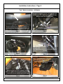
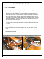
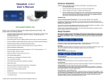
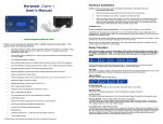
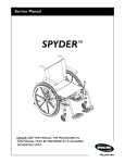
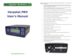
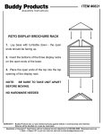
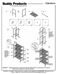
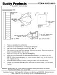
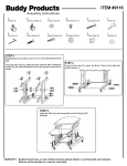
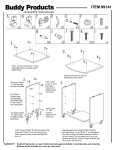
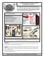
Custom Dynamics® Spyder TIPS-NS
Installation Instructions
We thank you for purchasing the Custom Dynamics® Spyder TIPS units!
Our products utilize the latest technology and high quality components to
ensure you the most reliable service. We offer one of the best warranty programs in the industry and we back our products with excellent customer
support, if you have questions before or during installation of this product
please call Custom Dynamics® at 1(800) 382-1388.
Part Number: SPY-TIPS-NS
Package Contents:
- Tips Module Assembly (2)
- Harness Connector Female (2)
- Harness Connector Male (2)
- Posi-Tap™ Connector (2)
- Black 4” Tie-Wrap (8)
Fender Side
Assembled
TIPS™ Unit plugs into stock
connector located
under A-frame.
Bike Side
Fits: 2013 & Up RS-S, ST-S, ST-Limited, RT-S, RT-Limited Models. Please see the specific instructions for your model
when routing the turn signal wires.
Preparation
Please take the time to verify the items in this kit and read the directions to fully to understand the installation. The bike
should be secured on a level surface while performing work.
Important: Before work can begin on the RT-Limited & ST/ST-S, the factory mirror assemblies must be removed from
the bike to allow access to the turn signal wires. Please refer to a detailed service manual or your local Spyder service
dealer for instructions on how to remove them. Custom Dynamics is not liable for damage resulting from improperly removed or installed equipment.
Note: Before turn signal wire can be routed, depending on your model, open the front hood, remove body panels to allow
access to areas wiring will be routed.
Questions? Call us at: 1 (800) 382-1388
M-TH 8:30AM-5:30PM / FR 9:30AM-5:30PM EST
07-2014SM
Installation Instructions - Page 2
Tips™ Module Installation - All Models
Plug the appropriate harness connector into each
side of the connector you unplugged on the bike.
Male to female and female to male.
Locate and unplug the connector coming from
the fender underneath the A-frame suspension.
Step 1
Step 2
Plug the TIPS™ module into each 3 pin connector, making sure the blue turn wire goes toward
the bike.
Step 2
Step 3
Wire is up through the top side panel, tie wrap as
needed and get ready to route to turn signal wiring. Go to next page and follow directions for
your model.
Route the blue wire up the A-frame, Tie wrap
wires as needed, then route wire up to front nose
area up top. (Panel must be up or removed)
Step 4
Questions? Call us at: 1 (800) 382-1388
Step 5
M-TH 8:30AM-5:30PM / FR 9:30AM-5:30PM EST
07-2014SM
Installation Instructions - Page 3
RS-S Models
6.
Remove Instrument cluster by following the instructions in your owners manual under the headlight bulb replacement section.
7.
Route blue wire up into the area behind instrument cluster. Use tie wraps as needed to keep away from hot or
moving parts.
8.
Locate the wires going to front turn signals. Test wires to determine which wire is the positive [ + ] wire going to
front turn signal. We would normally tell you a color wire to attach to, however, we have seen BRP reverse the
color code in these connectors with no rhyme or reason. Therefore, a test light is the best method to assure the
polarity is correct.
9.
Using the supplied Posi-Tap™ connectors, attach blue wire from the TIPS™ unit to the positive wire going to the
turn signals.
10. Test operation. TIPS™ unit will flash the fender lights in an alternating pattern with the front turn signal for maximum visibility.
11. Reinstall instrument cluster and covers.
ST & ST-S Models
6.
With the blue wire routed up through the body into the upper nose area, it must now be routed up to the turn signal area. Using a wire guide tool will simplify this process, a long flexible piece of wire or long zip-tie will work
well for fishing wire through the hard to reach places. Tie-wrap wires as need to prevent them from hanging or
coming in contact with hot/moving parts. (See Photo on next page for reference, model shown is an RT, but the
process is the same).
7.
Make sure the factory mirror assemblies have been removed from the bike to allow access to the turn signal
wires as noted on the first page. If you have not, please refer to a detailed service manual or your local Spyder
service dealer for instructions on how to remove them.
8.
With the mirror assembly removed, pull the slack on the cable until the entire length of it is showing. Your tap in
point should be as close to the bike as possible to allow the posi-Tap™ connections to fit back into the hole. (see
photo on page 4 for reference). You will need to strip the sheathing off the cable to allow tap in access to wire,
take care not to cut or fray wires while removing.
9.
Once the turn signal wires are exposed, test wires to determine which wire is the positive [ + ] wire going to front
turn signal. We would normally tell you a color wire to attach to, however, we have seen BRP reverse the color
code in these connectors with no rhyme or reason. Therefore, a test light is the best method to assure the polarity is correct.
10. Using the supplied Posi-Tap™ connectors, attach blue wire from the TIPS™ unit to the positive wire going to
each turn signal.
11. Tuck the turn signal wires back into the hole, take care that Posi-Tap is on the inside of the bike and not exposed.
12. Test operation of the TIPS™ units, power on the bike and test both left and right turn signals. All lights on the
fender should flash with alternately with the turn signals on the bike.
13. Re-install mirrors and body panels.
Questions? Call us at: 1 (800) 382-1388
M-TH 8:30AM-5:30PM / FR 9:30AM-5:30PM EST
07-2014SM
Installation Instructions - Page 4
RT-S & RT-Limited Models
6.
With the blue wire routed up through the body into the upper nose area, it must now be routed up to the turn signal area. Using a wire guide tool will simplify this process, a long flexible piece of wire or long zip-tie will work
well for fishing wire through the hard to reach places. Tie-wrap wires as need to prevent them from hanging or
coming in contact with hot/moving parts. (See photo below)
7.
Make sure the factory mirror assemblies have been removed from the bike to allow access to the turn signal
wires as noted on the first page. If you have not, please refer to a detailed service manual or your local Spyder
service dealer for instructions on how to remove them.
8.
With the mirror assembly removed, pull the slack on the cable until the entire length of it is showing. Your tap in
point should be as close to the bike as possible to allow the posi-Tap™ connections to fit back into the hole. (see
photo on page 4 for reference). You will need to strip the sheathing off the cable to allow tap in access to wire,
take care not to cut or fray wires while removing.
9.
Once the turn signal wires are exposed, test wires to determine which wire is the positive [ + ] wire going to front
turn signal. We would normally tell you a color wire to attach to, however, we have seen BRP reverse the color
code in these connectors with no rhyme or reason. Therefore, a test light is the best method to assure the polarity is correct.
10. Using the supplied Posi-Tap™ connectors, attach blue wire from the TIPS™ unit to the positive wire going to
each turn signal. (See Photo below)
11. Tuck the turn signal wires back into the hole, take care that Posi-Tap is on the inside of the bike and not exposed.
12. Test operation of the TIPS™ units, power on the bike and test both left and right turn signals. All lights on the
fender should flash with alternately with the turn signals on the bike.
13. Re-install mirrors and body panels.
Routing wire to turn signal
Questions? Call us at: 1 (800) 382-1388
Turn Signal Cable to the Mirror
M-TH 8:30AM-5:30PM / FR 9:30AM-5:30PM EST
07-2014SM