1
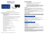
Herpstat Intro +
User’s Manual
Hardware Installation
WARNING: FIRE OR ELECTRICAL SHOCK MAY RESULT FROM MISUSE. FOR INDOOR USE ONLY!
Do not exceed 350 watts.
1.
Insert the temperature probe plug into jack on the back of the Herpstat Intro+.
2.
Attach the Herpstat's power cable to a standard 120V electrical outlet.
3.
Attach the heating device to the Herpstat's AC outlet. These devices may include heat tape, heat
coils, mats or other resistive load heating devices. Not recommended for use with rock heating
devices or other devices that come in direct contact with the animal. Not compatible with metal
rack systems or other setups that require grounded 3 prong cords.
Installation Tips:
Do not use aluminum tape on the probe tip. This can cause false readings and poor regulation.
If possible, route the probe wires so that they are not in direct contact with the 120vac cables going to the
heating devices. Preferably leave at least a few inches between the probe wires and the AC lines to avoid cross
talk/electrical interference issues.
www.spyderrobotics.com
Thank you for choosing the Herpstat Intro+ digital proportional thermostat. This
product offers the following features:
•
Proportional heating constantly monitors and adjusts amount of heat necessary to maintain a target
temperature (usable range from 40˚F to 150˚F or 4˚C to 65˚C). Can also be used in nonproportional (on/off) mode.
•
Built in Safety Relay on Herpstat Intro+ models to help protect against solid state failures causing
"run away" heating.
•
User selectable temperature ramping.
•
Sensor Matching allows the user to digitally calibrate the sensor output to match other equipment.
•
Auto Power Matching constantly adjusts the power output curve to match the enclosures efficiency.
•
Selectable day/night schedules with nighttime temperature setting.
•
High/Low temperature tracking helps monitor heating system and enclosure efficiency.
•
High/Low temperature threshold alarms.
•
Precision temperature sensor with an internal resolution of .1125 ˚F and are accurate to ± .9 ˚F
•
Display and setting in tenths of a degree.
•
Settings are retained in memory even if power is lost. *
•
Power Outage detection/tracking.
•
Temperature can be set/displayed in Fahrenheit or Celsius.
•
Easy to read backlit LCD display.
•
12ft removable sensor allow for easy replacement if necessary.
•
Audible alarm system.
•
Internal error detection shuts off heat if sensor fails or is disconnected.
•
Dual mounting options as a desktop or flanged mount.
•
Handles up to 350 watts of heating equipment.
•
Resettable fuse.
•
5.5ft input electrical cord.
•
1 year limited warranty
6" two prong (non-grounded) output cord.
* Software clock is reset and features requiring the clock are disabled on power loss.
The vent holes on the back of the Herpstat provide proper cooling. Mount the Herpstat in a dry location. During
operation it is normal for the Herpstat's enclosure to be warm to the touch.
Electrical surges can often damage a thermostat. Use a good quality surge suppressor connected to the wall
outlet and plug the Herpstat into it when possible.
Setup Procedure
Note: The Enter button is used to select options while the Plus and Minus buttons are used to alter
the options or navigate the menu. If no selection is made after a period of time the unit will return
to operation automatically. While in the menu system the AC power to the output is turned off for
safety.
Press the Enter button to display the initial menu screen. This menu allows you to select the daytime
temperature, the alarm setup, optional nighttime settings, and the system setup.
Day Temp:
The Daytime Temperature setting is the temperature the device will try to maintain during the Day Cycle. If the
Nite Cycle is disabled then the Daytime Temperature setting will be used for the full 24hrs.
Alarm Setup:
Enter this menu to enable the safety alarms.
HL Alarm=OFF/ON
To Enable/Disable the High/Low Alarms press the Enter button while on this display.
HighTemp Alarm:
This setting is the highest temperature at which the audible alarm triggers if breached.
LowTemp Alarm:
This setting is the lowest temperature at which the audible alarm triggers if breached for the selected output.
Timeout=OFF/ON (HL Alarm must be ON for this option to be enabled)
To Enable/Disable the Low Alarm Safety Timeout press the Enter button while on this display. This option is
used to add an additional safety measure should the temperature probe be dislodged from its normal position
which typically results in a "run away" heating scenario.
During initial power or after exiting the menu:
If enabled the timeout waits a 30 minute period. During this time any low alarms will not be triggered. At the
end of the timeout if the temperature has not exceeded the LowTemp Alarm setting the Herpstat will shut power
off to the heating device and display an alert message as well as beep. Pressing the Plus button will reset the
timeout for another 30 minutes. If the temperature exceeds the LowTemp Alarm setting the timeout will
automatically disable and the LowTemp alarm will function as normal.
During normal operation:
If the temperature drops below the LowTemp Alarm setting the timeout is triggered. The LowTemp alert is still
active during this scenario. Pressing the Plus button while on the temperature readout display will temporarily
mute the alarm. After the 30 minutes if the temp has not returned and exceeded the LowTemp Alarm setting
the Herpstat will shut power off to the heating device and display an alert message as well as beep. Pressing
the Plus button will reset the timeout for another 30 minutes.
The Display
In normal operation the Minus button will toggle between the available displays while the Plus button will
activate special features of that display. The Enter button will activate the menu system.
Nite Cycle:
Enter this menu to enable the night time temperature options. The System Clock must be set before this menu
is selectable.
IMPORTANT: This device uses a software based clock. Instead of a hardware based clock chip this
devices uses a software based clock. This works the same as most alarm clocks by counting the pulses on your
households electrical line which is regulated by your power company. In most cases this provides a very stable
method of keeping time. However, when power is disconnected the thermostat will not continue to keep track
of time. On power up the device reverts to the Day Temp and the Nite Cycle options are disabled until the
system clock is set. This method allows the Herpstat Intro+ cost to remain low while still providing some
additional advanced features which would not be otherwise possible.
Enable NC=OFF/ON
To Enable/Disable the Nite Cycle press the Enter button while on this display.
Nite Temp:
This setting is the temperature the device will maintain during the Nite Cycle.
NC Start Time:
This setting adjusts what time the Nite Cycle starts.
NC End Time:
This setting adjusts what time the Nite Cycle ends.
Ramping:
This setting adjusts how long it will take to switch between the DayTemp and NiteTemp settings allowing a
smooth transition up to 10 hours.
System Setup
Special Symbols:
An arrow symbol will appear if it is currently in a ramping session. A right arrow (→) will appear if the ramp is
increasing. A left arrow (←) will appear if the ramp is decreasing. A minus sign (-) will appear if a Low Alarm
has been breached. A plus sign (+) will appear if a High Alarm has been breached. A asterisk (*) will appear if
the night cycle has been enabled but the clock has not been set due to a power failure.
Power:
The percentage of power the Herpstat is applying to the heating device.
Recorded High / Low Temperatures:
This display indicates the highest and lowest temperature recorded for the probe. Pressing the + button will
reset the High/Low to the current reading.
System Information:
This display indicates the internal clock time and indicates the current time schedule which the Herpstat is
adhering to. If the Nite Cycle is disabled this display will not show.
Power Outage Monitor:
Each time the Herpstat is powered on it increments the Power Outage Monitor. To reset the monitor to zero
press the + button.
Getting the most out of your Herpstat
(Troubleshooting)
When setting up a new environment allow a minimum of one hour for the temperature to stabilize. Keep in
mind that all items in the enclosure are warming up including the enclosure walls. Probe placement will require
experimentation to achieve proper temperature regulation.
Note: Adjust the System Clock if using Nite Cycle options.
System Mode:
Select the System Mode option and set it to either Proportional, Non-Proportional. Proportional control allows
the unit to adjust the amount of power to the output. Non-Proportional provides full power until the
temperature setting is reached and then allows the temperature to drop a half degree before turning power back
on.
System Clock:
This setting adjusts the system clock's time. While setting the time the Plus button increments the hour and the
Minus button increments the minute.
Sensor Adjust:
The Sensor Adjust setting is used to alter the temperature read by the temperature probe to match other
equipment. Note: The sensor used in the Herpstat Probes are typically more accurate than most other
equipment. Adjustments to this setting are usually not necessary.
Display Mode:
This setting adjusts whether to display temperature in Celsius or Fahrenheit.
Master Reset:
Selecting this will reset all settings in the device to factory defaults.
Safety Relay:
Temperature:
This display shows the current temperature from the attached probe. If an error occurs a description will be
shown instead of the output information. The temperature the device is trying to achieve is in parentheses.
When ramping is enabled the value in parentheses will change according to the time based curve.
Options: Relay Disable, On Any Error, H-Alarm
This setting determines what course of action will take place during an error condition. This controls the built in
safety relay which can cut power to the AC output circuit in the event of a failure of the solid state component
(Triac) that controls the dimming. Once the error condition is corrected the device will return to normal
operations. On Any Error triggers the relay if any error condition exists while the H-Alarm option only triggers
the relay if the High Alarm has been triggered.
If after an hour of initial regulation the temperature does not reach within a degree of the target temperature
then this is an indication of insufficient heating source. Add an additional heat device to the enclosure or switch
to a higher wattage heat device. Do not exceed the maximum watts per output.
Should the device not work as expected it's possible one of the menu settings was set incorrectly. It may be
easier to reset the device to its factory default settings than to figure out which setting is causing the issue. To
do this enter the menu and perform the Master Reset option under the System Settings menu.
Do not use aluminum tape on the probe tip. This can cause false readings and poor regulation.
If possible route the probe wires so that they are not in direct contact with the 120vac cables going to the
heating devices. Preferably leave at least a few inches between the probe wires and the AC lines to avoid cross
talk/electrical interference issues.
Getting Help
Questions or comments can be e-mailed to: [email protected]
To purchase accessories please visit us on the web at: http://www.spyderrobotics.com
1 Year Limited Warranty
Spyder Robotics LLC warrants this product to be free from defects in workmanship and material for a period of one year from the date
of purchase by the original purchaser. The warranty period shall not extend beyond 2 years from the date Spyder Robotics LLC
shipped the product. During this warranty period Spyder Robotics LLC will repair or replace, at its option, any component parts that in
its opinion prove to be defective. Replacement parts may be new or serviceable used parts at Spyder Robotics LLC option, of equal or
better quality to those being replaced. This warranty does not extend and shall not apply to products that have been subjected to
misuse, neglect, accident, or improper installation.
THIS LIMITED WARRANTY AND REMEDY ARE EXCLUSIVE AND EXPRESSLY IN LIEU OF ALL OTHER WARRANTIES EXPRESSED OR
IMPLIED, INCLUDING BUT NOT LIMITED TO ANY IMPLIED WARRANTIES OF MECHANTABILITY AND FITNESS FOR A PARTICULAR
PURPOSE. IN NO EVENT SHALL SPYDER ROBOTICS BE LIABLE FOR LOST PROFITS, LOSS OF GOODWILL, OR ANY OTHER INCIDENTAL
OR CONSEQUENTIAL DAMAGES.
If you return your product to Spyder Robotics LLC for warranty service, proof of purchase may be required. A Return Material
Authorization (RMA) number must be obtained prior to the return. Spyder Robotics LLC is not responsible for material returned
without the RMA number clearly printed on the outside of the shipping container. To request an RMA number, contact Spyder Robotics
LLC with the description of failure, serial number of device, and date of purchase via e-mail at [email protected].