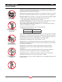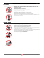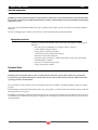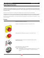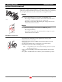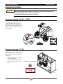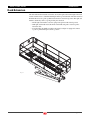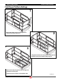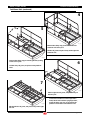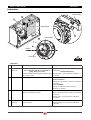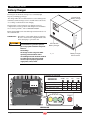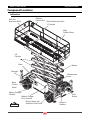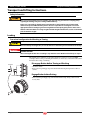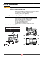
1
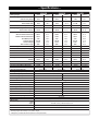
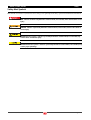
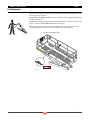
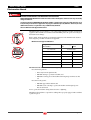
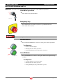
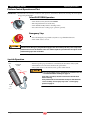
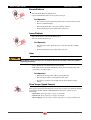
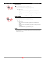
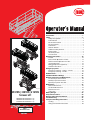
ART_2849
2591ES | 3391ES | 4191ES
Scissor Lift
2591ES Serial #11400001 – up
3391ES Serial #11500001 – up
4191ES Serial #11600001 – up
91831
December 2008
Introduction. . . . . . . . . . . . . . . . . . . . . . . . . . . . . . . . . . . . . . . . . . . 1
Safety. . . . . . . . . . . . . . . . . . . . . . . . . . . . . . . . . . . . . . . . . . . . . . . . . 2
Safety Alert Symbols . . . . . . . . . . . . . . . . . . . . . . . . . . . . . . . . . . . . 3
Fall Protection . . . . . . . . . . . . . . . . . . . . . . . . . . . . . . . . . . . . . . . . . . 4
Electrocution Hazard . . . . . . . . . . . . . . . . . . . . . . . . . . . . . . . . . . . 5
Tip-over Hazards. . . . . . . . . . . . . . . . . . . . . . . . . . . . . . . . . . . . . . . . 6
Fall Hazards . . . . . . . . . . . . . . . . . . . . . . . . . . . . . . . . . . . . . . . . . . . . 7
Collision Hazards . . . . . . . . . . . . . . . . . . . . . . . . . . . . . . . . . . . . . . . 7
Additional Safety Hazards. . . . . . . . . . . . . . . . . . . . . . . . . . . . . . . 8
Battery Safety . . . . . . . . . . . . . . . . . . . . . . . . . . . . . . . . . . . . . . . . . . 8
Jobsite Inspection . . . . . . . . . . . . . . . . . . . . . . . . . . . . . . . . . . . . . . 9
Function Tests . . . . . . . . . . . . . . . . . . . . . . . . . . . . . . . . . . . . . . . . . . 9
Operating Instructions . . . . . . . . . . . . . . . . . . . . . . . . . . . . . . . . 10
Prestart. . . . . . . . . . . . . . . . . . . . . . . . . . . . . . . . . . . . . . . . . . . . . . . . 10
Base Controls Operation and Test . . . . . . . . . . . . . . . . . . . . . . 11
Platform Control Operation and Test . . . . . . . . . . . . . . . . . . . 12
Joystick Operation . . . . . . . . . . . . . . . . . . . . . . . . . . . . . . . . . . . . . 12
Outrigger Operation (optional). . . . . . . . . . . . . . . . . . . . . . . . . 15
Shutdown Procedure . . . . . . . . . . . . . . . . . . . . . . . . . . . . . . . . . . 15
Emergency Systems. . . . . . . . . . . . . . . . . . . . . . . . . . . . . . . . . . . 16
Emergency Lowering – 2591ES – 3391ES . . . . . . . . . . . . . . . 16
Emergency Lowering – 4191ES. . . . . . . . . . . . . . . . . . . . . . . . . 16
Deck Extension . . . . . . . . . . . . . . . . . . . . . . . . . . . . . . . . . . . . . . . 17
Fold Down Platform Railings . . . . . . . . . . . . . . . . . . . . . . . . . . 18
Machine Inspections and Maintenance . . . . . . . . . . . . . . . . . 20
Pre-Start Inspection Checklist . . . . . . . . . . . . . . . . . . . . . . . . . . 21
Monthly Inspection Checklist . . . . . . . . . . . . . . . . . . . . . . . . . . 22
Quarterly Inspection Checklist . . . . . . . . . . . . . . . . . . . . . . . . . 23
Maintenance . . . . . . . . . . . . . . . . . . . . . . . . . . . . . . . . . . . . . . . . . 25
Routine Maintenance . . . . . . . . . . . . . . . . . . . . . . . . . . . . . . . . . . 26
Scheduled Maintenance . . . . . . . . . . . . . . . . . . . . . . . . . . . . . . . 26
Maintenance Lock . . . . . . . . . . . . . . . . . . . . . . . . . . . . . . . . . . . . . 26
Lubrication . . . . . . . . . . . . . . . . . . . . . . . . . . . . . . . . . . . . . . . . . . . . 27
Battery Charger . . . . . . . . . . . . . . . . . . . . . . . . . . . . . . . . . . . . . . 28
Component Locations. . . . . . . . . . . . . . . . . . . . . . . . . . . . . . . . . 30
Warning and Instructional Decals . . . . . . . . . . . . . . . . . . . . . . 34
Troubleshooting. . . . . . . . . . . . . . . . . . . . . . . . . . . . . . . . . . . . . . 36
Transport and Lifting Instructions. . . . . . . . . . . . . . . . . . . . . . 38
Loading . . . . . . . . . . . . . . . . . . . . . . . . . . . . . . . . . . . . . . . . . . . . . . . 38
Lifting and Tie Down Instructions . . . . . . . . . . . . . . . . . . . . . . 40
—Specifications—
2591ES
Working Height*
Platform Height
Platform Entry Height
Rails Up
Stowed Height
Rails Folded Down
3391ES
9.62 m*
39 FT*
12.06 m*
47 FT*
14.50 m*
25 FT
7.62 m
33 FT
10.06 m
41 FT
12.50 m
57 IN
1.45 m
66 IN
1.67 m
74 IN
1.88 m
100.5 IN
2.55 m
109.5 IN
2.78 m
119 IN
3.02 m
71 IN
1.80 m
79 IN
87.5 IN
2.22 m
2.01 m
Maximum Number of Occupants
5
5
4
Lift Capacity (Evenly Distributed)
2000 LB
907 kg
1500 LB
500 LB
227 kg
500 LB
With Roll-Out Deck Extended
180 IN
4.57 m
With Roll-Out Deck Retracted
132 IN
3.35 m
Roll-out Deck Capacity
4191ES
31 FT*
4
4
4
1000 LB
454 kg
227 kg
500 LB
227 kg
180 IN
4.57 m
180 IN
4.57 m
132 IN
3.35 m
132 IN
3.35 m
680 kg
Platform Dimensions
71 IN
1.80 m
71 IN
1.80 m
71 IN
1.80 m
Guardrail Height
44.5 IN
1.13 m
44.5 IN
1.13 m
44.5 IN
1,13 m
Toeboard Height
7.0 IN
18 cm
7.0 IN
18 cm
7.0 IN
18 cm
Roll-out Deck Length
48 IN
1.22 m
48 IN
1.22 m
48 IN
1.22 m
144 IN
3.66 m
144 IN
3.66 m
144 IN
3.66 m
4.57 m
180 IN
4.57 m
180 IN
4.57 m
Deck Width (inside)
Overall Length
With Outriggers
180 IN
91 IN
2.31 m
91 IN
2.31 m
91 IN
2.31 m
Wheel Base
102.5 IN
2.60 m
102.5 IN
2.60 m
102.5 IN
2.60 m
Wheel Track
78.5 IN
1.99 m
78.5 IN
1.99 m
78.5 IN
1.99 m
Overall Width
Turning Radius
Inside
76 IN
1.93 m
76 IN
1.93 m
76 IN
1.93 m
Outside
195 IN
4.95 m
195 IN
4.95 m
195 IN
4.95 m
12.0 IN
30.48 cm
12.0 IN
30.48 cm
12.0 IN
30.48 cm
Ground Clearance
Machine Weight** (Unloaded) (Approx.)
Ground Pressure/Wheel (Maximum)
8,600 LB**
3901 kg**
9,300 LB**
4218 kg**
10,300 LB**
4672 kg**
118 PSI
8.29 kg/cm²
120 PSI
8.43 kg/cm²
125 PSI
8.79 kg/cm²
3687 LB
Wheel Load
1672 kg
24 sec / 28 sec
Lift/Lower Speed (Approx.)
3747 LB
1699 kg
35 sec / 40 sec
Drive Speed (Platform Elevated)
0 – 0.5 MPH
0 –0.8 km/h
Drive Speed (Platform Lowered)
0 – 2.6 MPH
0 – 4.2 km/hr
45% / 24.2°
Gradeability
80 PSI
5.5 bar
Foam-Filled
Foam-Filled
150-165 FT/LB
204-225 Nm
Main System
3000 PSI
207 bar
Lift System
2500 PSI
172 bar
Steer
2000 PSI
103 bar
23 GAL
87 liters
Tire Pressure, 12 Ply Pneumatic
12 Ply Foam-Filled (Option)
Wheel Lug Nut Torque
Hydraulic Fluid Capacity
48 Volts DC
Power System – Voltage
Eight 6 Volt DC 350 amp hour industrial, deep cycle
Battery Pack
Battery Charger
45% / 24.2°
12-16.5 NHS “Outrigger”
Tire Size-Standard
Input
120 Volt AC, 50.60 Hz, 18 Amp—240 Volt AC, 50.60 Hz, 9 Amp
Output
Electric Motor
Brakes
Meets requirements of ANSI A92.6-2006 Section 4.
*Working height adds 6 feet (2 m) to platform height.
**Weight may increase with certain options or country standards.
48 Volt DC, 32 Amp, 1500 W, Timed Shutoff
8 h.p. (6 kW): 3600 rpm
Multi disc / Dual Rear Wheel
1768 kg
45 sec / 52 sec
2 Wheel Drive Standard, 4 Wheel Drive Option
Drive System (Proportional)
Hydraulic Pressure
3897 LB
2591ES | 3391ES | 4191ES
Introduction
Introduction
This Operator’s Manual has been designed to provide you, the customer, with the instructions and operating procedures essential to
properly and safely operate your MEC Aerial Work Platform for its intended purpose of positioning personnel, along with their
necessary tools and materials, to overhead work locations.
The Operator’s Manual must be read and understood prior to operating your MEC Aerial Work
Platform. The user/operator should not accept operating responsibility until he/she has read and
understands the operator’s manual as well as having operated the MEC Aerial Work Platform under
supervision of an authorized, trained and qualified operator.
It is essential that the operator of the aerial work platform is not alone on the workplace during
operation.
Modifications of this machine from the original design and specifications without written permission
from MEC are strictly forbidden. A modification may compromise the safety of the machine, subjecting
operator(s) to serious injury or death.
Your MEC Aerial Work Platform has been designed, built, and tested to provide safe,
dependable service. Only authorized, trained and qualified personnel should be allowed to
operate or service the machine.
MEC, as manufacturer, has no direct control over machine application and operation. Proper
safety practices are the responsibility of the user and all operating personnel.
If there is a question on application and/or operation contact:
MEC Aerial Platform Sales Corp.
1775 Park Street, Suite 77
Selma, CA 93662
USA
Phone: 1-800-387-4575
559-891-2488
Fax:
559-891-2448
www.mecawp.com
91831 – December 2008
Page 1
2591ES | 3391ES | 4191ES
Safety
Safety
DO NOT operate this machine until you have read and understood the Safety section of this manual, have performed the Jobsite
Inspection, Pre-Start Inspection and Routine Maintenance, and have completed all the test operations detailed in the Operating
Instructions section.
Failure to read, understand and follow all safety rules, warnings, and instructions will unnecessarily expose you and others to
dangerous situations. For your safety and the safety of those around you, you must operate your machine as instructed in this manual.
MEC designs aerial work platforms to be safe and reliable. They are intended to position personnel, along with their necessary tools
and materials, to overhead work locations. The owner/user/operator of the machine should not accept responsibility for the operation
of the machine unless properly trained.
ANSI and other applicable standards identify requirements of all parties who may be involved with self-propelled elevating work
platforms. The ANSI/SIA A92.56-2006 Manual of Responsibilities is considered a part of this machine and can be found in the manual
compartment, located at the platform control station. To ensure safe use of machine, inspections specified in ANSI/SIA A92.6-2006
Section 6.7 must be performed at designated intervals as prescribed.
Never perform service on the machine with the platform elevated without first blocking the scissor assembly using the maintenance
lock (see Maintenance Lock on page 26).
California Proposition 65 Warning
This product contains chemicals known to the State of California to cause cancer and/or birth
defects or other reproductive harm.
Page 2
91831 – December 2008
2591ES | 3391ES | 4191ES
Safety
Safety Alert Symbols
MEC manuals and decals use symbols and colors to help you recognize important safety, operation and maintenance information.
RED – Indicates an imminently hazardous situation which, if not avoided, will result in death or serious
injury.
ORANGE – Indicates a potentially hazardous situation which, if not avoided, could result in death or
serious injury.
YELLOW with alert symbol – Indicates a potentially hazardous situation which, if not avoided, may
result in minor or moderate injury.
YELLOW without alert symbol – Indicates a potentially hazardous situation which, if not avoided, may
result in property damage.
91831 – December 2008
Page 3
2591ES | 3391ES | 4191ES
Safety
Fall Protection
Operators must comply with employer, job site and governmental rules regarding the use of
personal protective equipment.
If required by your employer or job site, use personal fall protection equipment (PFPE) when
operating this machine.
All PFPE must comply with applicable governmental regulations, and must be inspected and
used in accordance with the PFPE manufacturer’s instructions.
Fall restraint must be properly attached to a designated anchorage point when driving or
operating the machine. Attach only one fall restraint to each anchorage point.
Lanyard Anchorage Points
Art_2836
1
9072
181
273
33 kg
kg
454
91730
kg
kg
261
400N
kg
kg
487
181
273
kg
kg
91385
454
33 kg
kg
181
214
400N
kg
kg
ART_2763 R1
Page 4
91831 – December 2008
2591ES | 3391ES | 4191ES
Safety
Electrocution Hazard
ELECTROCUTION HAZARD!!! THIS MACHINE IS NOT INSULATED!
DEATH OR SERIOUS INJURY will result from contact with or inadequate clearance from any electrically
charged conductor.
You must maintain a CLEARANCE OF AT LEAST 10 FEET (3.05 m) between any part of the machine, or its
load, and any electrical line or apparatus carrying over 300 Volts up to 50,000 Volts. One foot (30.5 cm)
additional clearance is required for every additional 30,000 Volts.
Observe Minimum Safe Approach Distance.
DO NOT work in close proximity to, or in contact with, energized power lines and electrical
equipment. This machine is not insulated and WILL NOT protect the operator from injury or
the machine from damage.
Refer to Table and all applicable governmental regulations for the minimum safe distances
from energized power lines and electrical equipment.
Minimum Save Approach Distance
Art_2824
Voltage
Minimum Safe Approach Distance
Phase to Phase
Feet
Meters
0 to 300 Volts
Avoid Contact
Over 300V to 50kv
10
3.05
Over 50KV to 200KV
15
4.60
Over 200KV to 350KV
20
6.10
Over 350KV to 500KV
25
7.62
Over 500KV to 750KV
35
10.67
Over 750KV to 1000KV
45
13.72
Art_2823
DO NOT touch the machine if it contacts energized power lines.
Personnel in the platform:
• Move away from the platform rails,
• DO NOT attempt to operate the machine, and
• DO NOT touch any part of the machine until energized power lines are shut
off.
Personnel on the ground:
• DO NOT approach the machine and
• DO NOT touch or attempt to operate the machine until energized power
lines are turned off.
Do not operate the machine during electrical storms or lightning.
DO NOT use the machine as a ground for welding unless properly equipped with a weld line
to platform option.
91831 – December 2008
Page 5
2591ES | 3391ES | 4191ES
Safety
Tip-over Hazards
DO NOT exceed the maximum platform capacity (see Specifications). The weight of options
and accessories will reduce the rated platform capacity and must be factored into the total
platform load. Refer to the decals on the options.
DO NOT elevate the platform when the machine is on a surface that is soft and / or on a slope.
If the alarm sounds when the platform is raised, use extreme caution to lower the platform.
Art_2828
DO NOT OVERLOAD
Driving: DO NOT drive the machine on a slope that exceeds the maximum uphill, downhill
or side slope rating. Slope rating applies to machines in the stowed position.
Slope rating is subject to ground and traction conditions.
Driving in stowed position: use extreme care and slow speeds when driving across uneven
terrain, debris, unstable or slippery surfaces, and near holes or drop-offs.
Driving with the platform elevated: DO NOT drive on or near uneven terrain, unstable
surfaces or other hazardous conditions.
DO NOT push off or pull toward any object outside the platform.
Art_2834
DO NOT DRIVE ON IRREGULAR OR
UNSTABLE SURFACE
Maximum Allowable Side Force
ANSI and CSA
150 lbs (667 N)
CE and AUS
90 lbs (400 N)
DO NOT elevate the platform when wind speeds are in excess of 28 m.p.h. (12.5 m/s). If these
wind speeds occur when the platform is elevated, carefully lower and discontinue operation.
DO NOT increase the surface area of the platform (i.e. cover the rails with tarp or plywood).
Increased surface area exposed to the wind will decrease machine stability.
DO NOT attach overhanging loads or use the machine as a crane.
Art_2833
DO NOT PUSH OR PULL
OBJECTSOUTSIDE PLATFORM
DO NOT transport tools and materials unless they are evenly distributed and can be safely
handled by personnel in the platform. Secure all tools and loose materials to prevent injury to
personnel below the platform.
DO NOT alter or disable machine components that may affect safety and stability.
DO NOT replace items critical to machine stability with items of different weight or
specification.
DO NOT modify or alter the work platform without written permission from MEC, as
modifications can increase weight and/or surface area resulting in instability.
DO NOT place ladders or scaffolds in the platform or against any part of the machine.
DO NOT use the machine on a moving or mobile surface or vehicle.
Art_2831
DO NOT ELEVATE IN WINDY
CONDITIONS
Ensure that all tires are in good condition, air filled tires are properly inflated and lug nuts are
properly torqued.
Art_2832
DO NOT USE AS CRANE
Page 6
91831 – December 2008
2591ES | 3391ES | 4191ES
Safety
Fall Hazards
DO NOT sit, stand or climb on the platform guard rails. Maintain a firm footing on the
platform floor at all times.
DO NOT exit the platform when elevated
DO NOT climb down from the platform when elevated.
Keep the platform floor clear of debris.
Art_2826
DO NOT CLIMB ON RAILS
DO NOT fasten a fall restraint lanyard to an adjacent structure.
Ensure that the entry is properly closed before operating the machine.
Operators must comply with employer, job site and governmental rules regarding the use of
personal protective equipment.
Art_2825
DO NOT EXIT PLATFORM WHEN
ELEVATED
Collision Hazards
Be aware of blind spots while operating this machine.
Watch for overhead obstructions when elevating the platform.
Watch for crushing hazards when holding the platform rail.
Reduce travel speed when moving the machine on slopes, when near personnel and obstacles,
or when surface conditions are wet, slippery or otherwise limiting.
Art_2835
DO NOT operate in the path of any crane unless the controls of the crane have been locked out
and/or precautions have been taken to prevent any possible collision.
Stunt driving and horseplay are PROHIBITTED.
Art_2829
Art_2827
91831 – December 2008
Page 7
2591ES | 3391ES | 4191ES
Safety
Additional Safety Hazards
Explosion and Fire Hazards
DO NOT operate the machine in hazardous locations or locations where potentially flammable
or explosive gasses or particles may be present.
Damaged Machine Hazards
Conduct a thorough pre-start inspection of the machine and test all functions before each work
shift to check for damage, malfunction and unauthorized modification. Tag and remove a
damaged, malfunctioning or modified machine from service. DO NOT use a damaged,
malfunctioning or modified machine.
Routine maintenance must be performed by the operator before each work shift. Scheduled
maintenance must be performed by a qualified service technician at scheduled intervals. Tag
and remove from service any machine that has not had scheduled preventative maintenance
performed.
Check that all safety and instructional decals are in place and undamaged.
Check that the operator’s, safety and responsibilities manuals are present in the storage
container located in the platform. All manuals must be complete, undamaged and readable.
Bodily Injury Hazards
DO NOT operate the machine when there is a hydraulic fluid or air leak. Hydraulic fluid or air
under pressure can penetrate and/or burn skin.
All compartments must remain closed and secure during machine operation. Improper
contact with components under any cover will cause serious injury. Only trained maintenance
personnel should access compartments. The operator should only access a compartment when
performing pre-operation inspection.
Weld Line to Platform Safety (if equipped)
Read, understand and follow all warnings and instructions provided with the welding power
unit.
Do not connect weld leads or cables unless the welding power unit is turned off at the platform
controls.
DO NOT operate unless the weld cables are properly connected.
Battery Safety
Burn Hazards
Batteries contain acid. Always wear protective clothing and eye wear when working with
batteries.
Avoid spilling or contacting battery acid. Neutralize battery acid spills with baking soda and
water.
Explosion Hazard
Keep sparks, flame and lighted tobacco away from batteries. Batteries emit explosive gas.
Electrocution Hazard
Avoid contact with electrical terminals.
Page 8
91831 – December 2008
2591ES | 3391ES | 4191ES
Safety
Jobsite Inspection
DO NOT operate this machine until you have read and understood the Safety section of this manual, have performed the Jobsite
Inspection, Pre-Start Inspection and Routine Maintenance, and have completed all the test operations detailed in the Operating
Instructions section.
Inspect the jobsite and determine whether the jobsite is suitable for safe machine operation. Do this before moving the machine to
the jobsite.
Be aware of changing jobsite conditions, and continue to watch for hazards while operating the machine.
Workplace Inspection
Check the jobsite where the machine will be used for all possible hazards, including but not
limited to:
• drop-offs or holes, including those concealed by water, ice, mud, etc.
• sloped, unstable or slippery surfaces
• bumps, surface obstructions and debris
• overhead obstructions and electrical conductors
• hazardous locations and atmospheres
• inadequate surface and support to withstand all load forces imposed by the machine
• wind and weather conditions
• the presence of unauthorized personnel
• other possible unsafe conditions
Function Tests
DO NOT operate this machine until you have read and understood the Safety section of this manual, have performed the
Pre-Start Inspection, Routine Maintenance, and Functions Test, have inspected the jobsite for hazards, and have learned the
operating procedures for this machine.
The operator must conduct a Functions Test of the machine before each work shift to check that all machine systems are working
properly.
Test the machine on a firm level surface with no debris, drop-offs, potholes or overhead obstructions. Perform each step outlined in
Operating Instructions on page 10.
DO NOT use a machine that is malfunctioning. If any function does not perform as described, tag the machine and remove for repair
by a qualified service technician. After repairs are completed, a Pre-Start Inspection and Functions Test must be performed before
using the machine.
91831 – December 2008
Page 9
2591ES | 3391ES | 4191ES
Operating Instructions
Operating Instructions
DO NOT operate this machine until you have read and understood the Safety section of this manual, have performed the Jobsite
Inspection, Pre-Start Inspection and Routine Maintenance, and have completed all the test operations detailed in the Operating
Instructions section.
This section provides instructions for each function of machine operation. Follow all safety rules and instructions.
This machine may be operated by trained and authorized personnel only. If multiple operators use this machine, all must be qualified
and authorized to use it. New operators must perform a Pre-Start Inspection and Functions Test prior to operating the machine.
Operators must comply with employer, job site and governmental rules regarding the use of personal protective equipment – see Fall
Protection on page 4.
Prestart
• Perform Prestart Inspection (see page 21).
• Check base control Emergency Stop Switch – turn clockwise to reset.
ART_2506 R1
• Check platform control Emergency Stop Switch – turn clockwise to reset.
ART_2507 R1
• Check Battery Disconnect Switch in Control Module next to Base Controls.
Must be in ON position.
ART_2356
• Check Charge Indicator on Base Control Panel.
Battery pack should be fully charged.
Note:
If machine fails to operate, check the Diagnostic LED on the motor control
processor inside the Control Module – see Component Locations on
page 30.
ART_2755 R1
Page 10
91831 – December 2008
2591ES | 3391ES | 4191ES
Operating Instructions
Base Controls Operation and Test
IMPORTANT—Be sure the area above the machine is clear of obstructions to allow full elevation of platform.
Select BASE Operation
M
FOR
PLAT
• Turn the Selector Key Switch to BASE.
OFF
E
BAS
ART_2357 R1
Emergency Stop
• Press the Emergency Stop Switch at any time to stop all machine functions.
• Turn switch clockwise to reset.
ART_2506 R1
Do not elevate the platform if the machine is not on a firm level surface.
Elevate Platform
• Press and hold the RAISE button on the base control panel to elevate the platform.
Test Operation
• Elevate to maximum height.
• Releasing the button will stop elevation.
E
RAIS
• Pressing the Emergency Stop Switch will stop elevation.
Lower Platform
ER
LOW
ART_2358 R1
• Press the LOWER button on the base control panel until the desired platform height
is reached.
Test Operation
• Lower the platform to the stowed position.
• Releasing the button will stop descent.
• Pressing the Emergency Stop Switch will stop descent.
91831 – December 2008
Page 11
2591ES | 3391ES | 4191ES
Operating Instructions
Platform Control Operation and Test
IMPORTANT—Check that the route of travel to be taken is clear of persons, obstructions, debris, holes, and drop offs, and is capable
of supporting the machine.
Select PLATFORM Operation
•
•
•
•
Turn the Selector Key Switch to PLATFORM.
Enter the platform and secure the entry.
Turn the Platform Key Switch to the ON position.
Press the horn button t verify proper operation (optional).
ART_2360 R1
Emergency Stop
• Press the Emergency Stop Switch at any time to stop all machine functions.
• Turn switch clockwise to reset.
ART_2507 R1
Activation of the Emergency Stop Switch will apply brakes immediately. This may cause unexpected
platform movement as the machine comes to a sudden stop. Brace yourself and secure objects on the
platform during operation of machine.
Joystick Operation
Steer
• Function speed is proportional and is controlled by the movement of the Joystick.
• The further it is moved forward, the faster the speed will be.
• The Joystick returns to the neutral (center) position when released.
Proportional
Joystick
Forwa
rd
Lower
Revers
e
Lift
Do not elevate platform unless guardrails are installed and secure
– see Fold Down Platform Railings on page 18.
If the deck is extended, check for clearance beneath the deck
before lowering.
If the platform fails to lower DO NOT attempt to climb down the
scissor assembly. Serious injury may result – see Emergency
Systems on page 16.
Enable
Bar
ART_2363
Page 12
91831 – December 2008
2591ES | 3391ES | 4191ES
Operating Instructions
Elevate Platform
• Place the Enable Bar in the LIFT position.
• Squeeze the Enable Bar and move the Joystick toward you.
ART_2386 R1
Test Operation
• Rate of lift is proportional and is dependent on the movement of the Joystick.
• Elevate to maximum height.
• Releasing the Enable Bar or the Joystick will stop elevation.
• Pressing the Emergency Stop Switch will stop elevation.
Lower Platform
• Place the Mode Select Switch in the LIFT position.
• Move the Joystick away from you.
Test Operation
• Rate of descent is fixed - platform lowers at same rate regardless of handle
position.
ART_2386 R1
• Pressing the Emergency Stop Switch will stop descent.
Steer
Check that the route is clear of persons, obstructions, debris, holes and drop -offs, and is capable if
supporting the machine.
• Always check front steer wheel direction before driving.
• With the Mode Select Switch in the DRIVE position, press the Steering Switch with
your thumb to steer left or right.
Test Operation
• Releasing the Steering Switch will stop steering function.
• The steer wheels will not center themselves after a turn.
• They must be returned to the straight-ahead position with the Steering
Switch.
Drive Torque (Speed Control)
ART_2388 R1
91831 – December 2008
Drive speed is selectable until the platform is elevated above 10 Feet (3 m). When the platform
is elevated the machine defaults to MID RANGE and the switch is locked-out (non
functioning).
• HIGH SPEED: allows speeds up to 3.0 m.p.h. (4.8 km/h).
• MID RANGE: allows speeds up to 1.0 m.p.h. (1.6 km/h).
• HIGH TORQUE: use to drive up or down a slope that is too steep for normal speed.
Page 13
2591ES | 3391ES | 4191ES
Operating Instructions
Drive Forward
• Place the Mode Select Switch in the DRIVE position.
• Squeeze the Enable Bar and move the Joystick away from you.
Test Operation
ART_2362 R1
• Drive speed is proportional and is dependent on the movement of the
Joystick.
• Releasing the Enable Bar or returning the Joystick to the center position will
stop drive.
• Pressing the Emergency Stop Switch will stop drive.
Drive Reverse
• Place the Mode Select Switch in the DRIVE position.
• Squeeze the Enable Bar and move the Joystick toward you.
Test Operation
ART_2362 R1
• Drive speed is proportional and is dependent on the movement of the
Joystick.
• Releasing the Enable Bar or returning the Joystick to the center position will
stop drive.
• Pressing the Emergency Stop Switch will stop drive.
Brake
• For parking, the brake is automatically applied when the Joystick is positioned in the
neutral (center) position.
Page 14
91831 – December 2008
2591ES | 3391ES | 4191ES
Operating Instructions
Outrigger Operation (optional)
Only lower the outriggers when the machine is on a firm, level surface. The surface must be
capable of supporting the maximum ground pressure per wheel/outrigger (see specifications).
The Outrigger Control Switch is located on the front face of the Upper Control Box.
Extend
Push down and hold the Outrigger Control Switch to the EXTEND position.
• The outriggers will extend and level the machine. When the machine is level
and ready to operate, the outriggers will stop automatically.
ART_2370
• The Indicator Lamp will turn OFF, indicating that outriggers are down and
machine drive function is disabled.
Retract
E
DRIV
D
BLE
ENA
T
RAC
RET
Push up and hold the Outrigger Control Switch to the RETRACT position.
TIC
OMA S
AUT IGGER
END
R
EXT
OUT
IN
ITCH N
D SW CTIO
HOL D DIRE
IRE
DES
• The outriggers will retract.
9
9134
ART_2371
• The Indicator Lamp will turn ON, indicating that the outriggers are up and
machine drive function is enabled.
Shutdown Procedure
• When finished with the machine, place the platform in the stowed position.
• Park the machine on a level surface.
• Turn the Selector Key Switch to the OFF position and remove the key to prevent
unauthorized use.
• Carefully exit the platform using a constant three (3) point dismount/grip.
• Turn the Battery Disconnect Switch to the OFF position.
Leaving the Battery Disconnect Switch in the ON position for an extended
time will drain the battery.
• Always put the switch in OFF position when leaving the machine at the end of the
work day.
• Put a padlock on the Battery Disconnect Switch to prevent unauthorized operation.
Note:
ART_2387
91831 – December 2008
Page 15
2591ES | 3391ES | 4191ES
Emergency Systems
Emergency Systems
If the control system fails while the platform is elevated, have an experienced operator use the
emergency lowering procedure to safely lower the platform.
Do not attempt to climb down beams (scissors) assembly.
Emergency Lowering – 2591ES – 3391ES
The Emergency Lowering System is used
to lower the platform in case of power or
valve failure. To lower the platform, pull
the red “T” handle located at the rear of the
machine. Lowering stops when you release
the “T” handle.
ART_3055
91083
Emergency Lowering – 4191ES
The Emergency Lowering System is used to
lower the platform in case of power or valve
failure. To lower the platform, perform the
following steps:
• Push and hold the toggle switch down
to lower the platform.
• Once the platform is fully lowered,
release the toggle switch to close the
valve.
51
Emergency Lowering Switch
ART_3056
Page 16
91831 – December 2008
2591ES | 3391ES | 4191ES
Deck Extension
Deck Extension
The deck will extend in intervals of 8 inches (20 cm) throughout the entire length of the deck
extension. There are two (2) handles that hang from the top rail at the end of the deck extension
Both handles are used to push or pull the deck extension to the desired position. The right-side
handle is attached by cable to a spring-loaded pin at the deck.
• Lift the right-side handle to raise the spring loaded pin from the locked position.
• With right-side handle raised, lift the left-side handle and push to extend or pull to
retract the deck.
• Lower the right-side handle enough for the spring-loaded pin to engage and continue
to push or pull until the pin locks into position.
ART_2764
91831 – December 2008
Page 17
2591ES | 3391ES | 4191ES
Fold Down Platform Railings
Fold Down Platform Railings
1
ART_2837
Remove the safety snap pins holding the front
extension rail to the corner post.
2
3
ART_2838
Swing the front extension rail back, next to the right side
extension rail and secure with a safety snap pin.
ART_2839
Remove the safety snap pin from the rear right side
extension rail corner post.
Lift the rail, pivot, and place on the platform floor.
Page 18
continued…
91831 – December 2008
2591ES | 3391ES | 4191ES
Fold Down Platform Railings
Fold Down Rails (continued)
4
5
ART_2840
Remove the safety snap pin from rear left side
extension rail corner post.
Lift the rail, pivot and place on top of the right side
extension rail.
ART_2841
Remove the safety snap pins holding the entry railing
to the corner posts.
6
Lift the entry rail, pivot, and place on the platform
floor.
7
ART_2842
Lift the right side rail, pivot, and place on top of
the entry rail.
ART_2843
To return the machine to normal operation
mode, lift all rails into their upright position,
install all safety snap pins, and position the
platform control box on the extension rail.
Lift the left side rail, pivot, and place on top of the right
side rail.
91831 – December 2008
Page 19
2591ES | 3391ES | 4191ES
Machine Inspections and Maintenance
Machine Inspections and Maintenance
DO NOT operate this machine until you have read and understood the Safety section of this manual, have performed the Jobsite
Inspection, Pre-Start Inspection and Routine Maintenance, and have completed all the test operations detailed in the Operating
Instructions section.
The operator must conduct a thorough Pre-Start Inspection of the machine and test all functions before each work shift to check for
damage, malfunction and unauthorized modification.
Tag and remove a damaged, malfunctioning or modified machine from service. DO NOT use a damaged, malfunctioning or modified
machine.
Use the Pre-Start Inspection to determine what Routine Maintenance is required. The operator may perform only the routine
maintenance items specified in this manual.
IMPORTANT— Scheduled maintenance inspection checklists are included in this manual for use only by qualified service
technicians. Only qualified service technicians may perform repairs to the machine. After repairs are completed,
the operator must perform a Pre-Start Inspection before proceeding to the Functions Test.
Always use the maintenance lock to block the scissor assembly in place before servicing the machine
with the platform elevated.
Hydraulic fluid under pressure can penetrate and burn skin, damage eyes, and may cause serious
injury, blindness, and death. Repair leaks immediately. Fluid leaks under pressure may not always be
visible. Check for pin hole leaks with a piece of cardboard, not your hand.
Perform scheduled maintenance at recommended intervals. Failure to perform scheduled
maintenance at recommended intervals may result in a defective or malfunctioning machine and may
result in injury or death of the operator. Keep maintenance records current and accurate.
Immediately report any damage, defect, unauthorized modification or malfunction to your supervisor.
Any defect must be repaired prior to continued use. DO NOT use a damaged, modified or
malfunctioning machine.
Never leave hydraulic components or hoses open. Plug all hoses and fitting immediately after
disassembly to protect the system from outside contamination (including rain).
Never open a hydraulic system when there are contaminants in the air.
Always clean the surrounding area before opening hydraulic systems.
Use only recommended lubricants. Improper lubricants or incompatible lubricants may cause as much
damage as no lubrication.
Watch for makeshift “fixes” which can jeopardize safety as well as lead to more costly repair.
Inspection and maintenance should be performed by qualified personnel familiar with the equipment.
Page 20
91831 – December 2008
2591ES | 3391ES | 4191ES
Machine Inspections and Maintenance
Pre-Start Inspection Checklist
The operator must conduct a thorough Pre-Start Inspection of the machine before each work shift.
General Inspection Checklist
Initial
Description
_______ Check that the operator’s, safety, and responsibilities manuals are in the storage container located on the platform.
_______ Perform a visual inspection of all machine components. Look for missing parts, torn or loose hoses, hydraulic fluid
leaks, torn or disconnected wires, damaged tires etc.
_______ Check all structural components of the machine for cracked welds, corrosion and collision damage.
_______ Check all hoses and the cables for worn or chafed areas.
_______ Check the platform rails and sliding mid-rail entry for damage or modification.
_______ Check that all warning and instructional decals are legible and secure.
_______ Check the tires for damage.
_______ Check the tire pressure (not required for foam filled tires).
_______ Check the lower limit switch for visual damage or loose or missing hardware.
_______ All structural components, pins and fasteners are present and properly tightened.
Fluid Level Checklist
_______ Check for fluid leaks.
_______ Hydraulic fluid level (check with platform fully lowered).
Secure for operation
_______ Secure all covers and panels.
91831 – December 2008
Page 21
2591ES | 3391ES | 4191ES
Machine Inspections and Maintenance
Monthly Inspection Checklist
This checklist must be used at monthly intervals or every 100 hours of machine use, whichever occurs
first. Failure to do so could result in death or serious injury.
Scheduled Maintenance Inspections should be conducted by qualified service technicians only. Photocopy this page for reuse. Keep
inspections records up to date. Record and report all discrepancies to your supervisor.
Model Number _______________ Serial Number ________________________ Hour Meter Reading_________________
Initial
Description
_______ Perform all checks listed on Prestart Inspection.
_______ Inspect the condition of hydraulic fluid in the reservoir. Oil should have a clear amber color.
_______ Check battery electrolyte level and connections.
_______ Check wheel lug nuts for proper torque (see “Machine Specifications”).
_______ Check if tires are leaning in or out.
_______ Inspect all beams and pivot points for signs of wear and/or damage.
_______ Check the pin joints and retaining rings for security.
_______ Inspect the entire machine for signs of damage, broken welds, loose bolts, improper or makeshift repairs.
_______ Check that the platform does not drift down with a full load.
_______ Lubricate the axle float cylinder pivot mounts (see Lubrication Chart).
_______ Check all wire connections.
_______ Check that all adjustable flow valves are locked, check setting if any are not locked.
_______ Check outriggers for proper operation (if equipped).
DATE________INSPECTED BY __________________________________________
Page 22
91831 – December 2008
2591ES | 3391ES | 4191ES
Machine Inspections and Maintenance
Quarterly Inspection Checklist
This checklist must be used at quarterly intervals or every 300 hours of machine use, whichever occurs
first. Failure to do so could result in death or serious injury.
Scheduled Maintenance Inspections should be conducted by qualified service technicians only. Photocopy this page for reuse. Keep
inspections records up to date. Record and report all discrepancies to your supervisor.
Model Number _______________ Serial Number ________________________ Hour Meter Reading_________________
Initial
Description
_______ Perform all checks listed on Prestart/Monthly Inspection.
_______ Check the operation speeds to ensure they are within specified limits (see Specifications).
_______ Check the emergency lowering system.
_______ Clean and lubricate all push button switches with dry lubricant and ensure that the switches operate freely in all
positions.
_______ Check the tightness of the platform frame and the linkage pins.
_______ Check the overall platform and guardrail component stability.
_______ Check the electrical mounting and hardware connections for security.
_______ Check the king pins for excessive play.
Additional maintenance requirements for severe conditions
_______ Replace hydraulic filter element (under normal conditions replace every six [6] months).
DATE________INSPECTED BY __________________________________________
91831 – December 2008
Page 23
ANNUAL INSPECTION
Annual Inspection
Report
Aerial Platform Sales Corp.
1775 Park Street, Suite 77 • Selma, CA 93662 USA
800-387-4575 • 559-891-2488 • Fax: 559-891-2493
Date
Serial Number
Model Number
Date Of Last Inspection
Date Placed In Service
Dealer
Street
City/State/Zip
Phone Number
Contact
Customer
Street
City/State/Zip
Phone Number
Contact
• Check each item listed below.
Key:
• Use proper Operator's, Service and Parts manual for specific information and settings.
• If an item is found to be "Unacceptable" make the necessary repairs and check the
"Repaired" box.
• When all items are "Acceptable", the unit is ready for service.
• Please fax a copy to MEC at (559) 891-2488 or email to EMAIL ADDRESS
Y N R U
Decals:
Proper Placement/Quantity
Legibility
Correct Capacity Noted
Rails:
All Rail Fasteners Secure
Entry Gate/Chain Closes Properly
Manual/Safety Data In Box
Rear Rail Pad In Place
Extending Platform:
Slides Freely
Latches In Stowed Position
Latches In Extended Position
Rail Latches Work Properly
Cable Secure
Platform:
Platform Bolts Tight
Platform Structure
Platform Overload System:
Functional
Calibrated
Wire Harnesses:
Mounted Correctly
Physical Appearance
110/220V Outlet Safe/Working
Scissors:
Beam Structures
Welds
Retaining Rings
Upper Cylinder Pins Secure
Lower Cylinder Pins Secure
Lower Beam Mounts tight
Rollers Turn Freely
Maintenance Locks:
Secure
Operational
"Y"
"N"
"R"
"U"
Yes/Acceptable
No/Unacceptable
Repaired
Unnecessary/Not Applicable
Y N R U
Base:
Cover Panels Secure
Base Fasteners Tight
Bolts Tight
Front Axle Mounting (4WD)
Rear Axle Mounting (4WD)
Front Axle/Front Wheel Assemblies:
Wheel Motors-Mounting Secure
Wheel Motors-Leaks
Lug Nuts Torqued Properly
Steering Cylinder Pins Secure
Pivot Points Lubed
Drive Assembly Front Hubs:
Castle Nut Torqued Properly
Cotter Pinned
Rear Axle/Rear Wheel Assemblies:
Brakes Operational
Wheel Motors-Mounting Secure
Wheel Motors-Leaks
Lug Nuts Torqued Properly
Axle Pivot Libed (4WD)
Axle Lock Operational
Component Area:
Valve Manifold(s) Secure
Hoses Tight/No Leaks
D/C Mtr(s) Secure/Operational
Contactors Secure
Pump Secure
Batteries:
Secure
Fully Charged
Battery Charger:
Secure
Operational
Emergency Stop:
Breaks All Circuits
Y N R U
Operation:
Wires Tight
Switches Secure
All Functions Operational
Emergency Down:
Operational
Slow Speed Limit Switch:
Set Properly
Pothole Bars:
Operate Smoothly
Lock In Place
Limit Switches Adjusted
Pressures & Hydraulics:
Oil Filter Secure/Chg
Oil Level Correct/Chg
Steering Pressure Set
Drive Pressurre Set
Lift Pressure Set
Engine:
Engine Mounts Tight
Fuel Lines Secure
Fuel Lines Free Of Leaks
Fuer Tanks Secure
Fuel Shut Off Valves Func.
All Shields/Guards In Place
Oil Level
Oil Filter
Air Filter
Options Operational:
Hour Meter
Battery Indicator
Warning Light
Warning Horn
Generator
Converter
Comments:
November 2007
Signature/Mechanic:
Signature/Owner-User:
Date:
Operator's Manual
Date:- 3072ES | 3772ES
Page
P/N 90728 Rev.
2 33
2591ES | 3391ES | 4191ES
Maintenance
Maintenance
DO NOT operate this machine until you have read and understood the Safety section of this manual, have performed the Jobsite
Inspection, Pre-Start Inspection and Routine Maintenance, and have completed all the test operations detailed in the Operating
Instructions section.
Tag and remove a damaged, malfunctioning or modified machine from service. DO NOT use a damaged, malfunctioning or modified
machine.
Use the Pre-Start Inspection to determine what Routine Maintenance is required. The operator may perform only the routine
maintenance items specified in this manual.
IMPORTANT—Scheduled maintenance inspection checklists are included in this manual for use only by qualified service
technicians. Only qualified service technicians may perform repairs to the machine. After repairs are completed,
the operator must perform a Pre-Start Inspection before proceeding to the Functions Test.
Always use the maintenance lock to block the scissor assembly in place before servicing the machine
with the platform elevated.
Hydraulic fluid under pressure can penetrate and burn skin, damage eyes, and may cause serious
injury, blindness, and death. Repair leaks immediately. Fluid leaks under pressure may not always be
visible. Check for pin hole leaks with a piece of cardboard, not your hand.
Perform scheduled maintenance at recommended intervals. Failure to perform scheduled
maintenance at recommended intervals may result in a defective or malfunctioning machine and may
result in injury or death of the operator. Keep maintenance records current and accurate.
Immediately report any damage, defect, unauthorized modification or malfunction to your supervisor.
Any defect must be repaired prior to continued use. DO NOT use a damaged, modified or
malfunctioning machine.
Never leave hydraulic components or hoses open. Plug all hoses and fitting immediately after
disassembly to protect the system from outside contamination (including rain).
Never open a hydraulic system when there are contaminants in the air.
Always clean the surrounding area before opening hydraulic systems.
Use only recommended lubricants. Improper lubricants or incompatible lubricants may cause as much
damage as no lubrication.
Watch for makeshift “fixes” which can jeopardize safety as well as lead to more costly repair.
Inspection and maintenance should be performed by qualified personnel familiar with the equipment.
91831 – December 2008
Page 25
2591ES | 3391ES | 4191ES
Maintenance
Routine Maintenance
IMPORTANT— The operator may perform routine maintenance only. Scheduled maintenance must be performed by qualified
service technicians.
Charge Batteries See Battery Charger on page 28
Pre-Start Inspection Perform routine maintenance as identified in the Pre-Start Inspection Checklist on page 21.
Scheduled Maintenance
Maintenance performed monthly, quarterly, annually and bi-annually must be performed by a
qualified service technicians trained and authorized to perform maintenance on this machine,
and must be done in accordance with the procedures outlined in the service manual. Scheduled
maintenance inspection checklists are included in this manual for use by qualified service
technicians.
Machines that have been out of service for more than three months must receive the quarterly
inspection before returning to service.
Maintenance Lock
Never perform service on the machine with the
platform elevated without first blocking the
scissor assembly using the maintenance lock.
Maintenance Lock In Position
REAR
ART_3057
Page 26
91831 – December 2008
2591ES | 3391ES | 4191ES
Maintenance
Lubrication
Grease Fitting
1
2
Sight Gauge
15
4
3
Add Oil Here
LEVEL
Fill to Here
ART_3054
Lubrication
No.
ITEM
SPECIFICATION
1
Hydraulic
Reservoir
Routine Maintenance
Mobile Fluid 424
Check Daily
Do not substitute with lower grade fluids as
Scheduled Maintenance
pump damage may result.
Fill to the middle of the sight gauge with platform in Change yearly or every 1000 hours, whichever
occurs first
the stowed position.
2
Hydraulic Filter
Filter Element
Scheduled Maintenance
Normal Conditions
Change every six months or 500 hours, whichever
occurs first
Severe Conditions
Change every three months or 300 hours,
whichever occurs first
3
Hubs
SAE 90 Multipurpose Hypoid Gear Oil
API Service Classification GL5
Scheduled Maintenance
Check every three months or 250 hours, whichever
occurs first
Change yearly or every 1000 hours, whichever
occurs first
4
Axle Float
Cylinder
Lithium N.L.G. #2 EP
Purge old grease.
Scheduled Maintenance
Change monthly or every 25 hours, whichever
comes first.
91831 – December 2008
FREQUENCY
Page 27
2591ES | 3391ES | 4191ES
Battery Charger
Battery Charger
The charger is an advanced, microprocessor controlled, high
frequency switching type charger.
Control Panel
Battery Charge
Indicator
The charger will work even with batteries in a severe discharge state
with battery terminal voltages as low as 4V. This reduces the need to
“boost charge” weak batteries before charging.
The charger has a 22 hour timer in case charging can not be
completed due to battery problems. The charger senses and flashes
error codes for problems – refer to SERVICE MANUAL.
51
Battery charger LEDs can be viewed through a window in the door of
the Control Module.
IMPORTANT— Unit will not operate when charger is plugged in.
Be sure to disconnect the charger from the outlet
before attempting to operate the unit.
LED Window
Battery Charger
Lead-acid batteries generate explosive
gases. Keep sparks and flame away from
batteries.
No Smoking!
The charger surface can get hot while
operating. Contact with the skin or
surrounding materials should be avoided.
Battery Charger
AC Connector
ART_2372R1
To reduce the risk of an electric shock,
connect only to a properly grounded
single-phase (3 wire) outlet.
BATTERY CHARGER
INDICATOR
YELLOW
80%
100%
FAULT
HSB1500-48
INDUSTRIAL
BATTERY CHARGER
STATUS
AUTO SELECTABLE DUAL AC INPUT
100 - 240V ~ 50/60 Hz 18A
48V
25A
No AC power to charger
OFF
OFF
OFF
OFF
Normal operation, charger is charging
ON
OFF
OFF
OFF
Normal, battery is over 80% charged
ON
ON
OFF
OFF
Normal, battery is 100% charged
OFF
OFF
ON
OFF
FAULT
Please see service manual for additional information.
STATUS
ALL LED’S MUST BE OFF BEFORE
CONNECTING TO AC POWER
FAULT
80% 100%
HB1500-48
Page 28
ART_2374
91831 – December 2008
2591ES | 3391ES | 4191ES
Battery Charger
Charge Batteries
1 Plug the charger into a single phase AC socket with a nominal voltage rating of 100V,
110V, 115V, 120V, 220V, 230V, or 240V and a frequency rating of 50 or 60Hz.
• The charger automatically senses and adjusts to the AC voltage and frequency.
• At 110/120V the wall socket circuit breaker should be a 20A breaker with no other
loads on the circuit.
2 The charger will start automatically within a few seconds and begin charging the
batteries.
3
•
•
•
•
•
•
•
The LED’s indicate the charging progress.
The yellow LED will turn ON and remain ON throughout the charging cycle.
When the battery is 80% charged the green 80% LED will turn ON.
When the battery is fully charged the green 100% LED will turn ON and the green
80% LED will turn OFF.
When the battery is fully charged the yellow LED will turn OFF indicating that the
charger is no longer charging.
Charging time is dependent on depth of battery discharge, battery condition, and
temperature.
If the charger is left plugged in after charging is complete (100% LEDON) the charger
goes into maintenance mode to keep batteries charged while in storage.
The charger continuously measures battery voltage and restarts the charging cycle if
the battery voltage drops below about 50V. This keeps batteries charged while in
storage but does not boil-out the electrolyte over time.
4 Red FAULT LED
• ON: Battery pack probably bad, weak, or a bad cell.
• 1 FLASH: Open or short circuit. Remove from service until problem is identified and
corrected.
• 2 FLASH: Charger timed out. Battery pack probably bad, weak, or a bad cell. Unplug
for 30 seconds, then plug in to start a new charge cycle.
Note:
New batteries sometimes need 20 to 30 charge/discharge cycles before they
charge normally. The charger LEDs may only show yellow or 80% LED ON
after overnight charging. Within a few weeks the 100% LED will turn ON
at the end of the charge cycle.
5 Turn OFF charger by unplugging (disconnect from AC voltage).
Note:
91831 – December 2008
There may be up to a one (1) minute delay for the charger to turn off after
AC power supply is disconnected.
Page 29
2591ES | 3391ES | 4191ES
Component Locations
Component Locations
Full Machine
Platform
Control Box
Roll-Out
Extension Deck
Rollout Extension Deck
"H" Handle
Main
Platform Deck
Lift
Cylinder
Base
Beams
Outrigger
Maintenance
Lock
Base
Control
Panel
Battery Charger
Window
ART_2845
Page 30
51
Limit
Switch
Battery Charger
AC Connector
Electric Motor and
Hydraulic Fluid Pump
Power to
Platform
91831 – December 2008
2591ES | 3391ES | 4191ES
Component Locations
Modules
CONTROL MODULE
Battery
Disconnect Switch
Fuse
GP400
GP600
LED Motor Control
LED
Relay
Main Relief
Manifold
Hydraulic Fluid
Filter
GP600
Motor Control
Module
GP400
Module
Hydraulic
Reservoir
Hydraulic
Fluid Level
Sight Guage
51
15
Lower Controls
Alarm
Emergency
Lowering Switch
Hydraulic
Manifold
Battery Charger
AC Connector
Battery
Charger
POWER MODULE
12 Volt DC Battery
Emergency Lowering
ART_3053
91831 – December 2008
Battery Pack
Eight 6 Volt DC Batteries
Page 31
2591ES | 3391ES | 4191ES
Component Locations
Upper Controls
Lift / Drive 4
6
Speed / Torque
Keyswitch, Off/On 5
7
Emergency Stop
Steering 3
8
Horn (Optional)
9
Drive Enabled Indicator
(Optional)
10
Outrigger Extend/Retract
(Optional)
Joystick 1
E
DRIV
D
BLE
ENA
RET
Enable Bar 2
RAC
T
TIC
OMA S
AUT IGGER
ND
R
EXTE
OUT
CH IN
SWIT TION
HOLD DIREC
IRED
DES
ART_2348 R1
CONTROL
1
Joystick
DESCRIPTION
DRIVE
Controls Forward and Reverse travel at stepped speeds.
LIFT
Move toward operator to elevate platform. Lift speed increases proportional to the
Joystick movement
Move away from operator to lower platform. Speed is fixed.
2
Enable Bar
Squeeze to enable DRIVE, STEER, and LIFT from Joystick.
3
Steering Switch
Using thumb, press and hold the rocker switch to steer Left or Right.
4
Mode Selector
Select LIFT or DRIVE function for Joystick.
5
Key Switch
Turn power ON or OFF at the platform. Does not affect lower controls.
6
Speed / Torque
Switch
HIGH TORQUE
Slow speed. Provides maximum torque for rough terrain.
MID RANGE
Mid speed. Provides medium torque for smooth to moderate terrain.
HIGH SPEED
Provides high speed when platform height is below 10 feet (3 m).
7
Emergency Stop
Switch
PUSH to stop all machine functions.
TURN CLOCKWISE to reset.
8
Horn (option)
Press to sound warning horn.
9
Indicator Lamp
(outrigger option)
Lamp ON
Outriggers are UP and machine will drive.
Lamp OFF
Outriggers are DOWN and machine will not drive.
RETRACT
Push toggle switch UP to retract (raise) outriggers.
EXTEND
Push toggle switch DOWN to extend (lower) outriggers.
10 Retract / Extend
(outrigger option)
Page 32
91831 – December 2008
2591ES | 3391ES | 4191ES
Component Locations
Lower Controls
4 Emergency Stop
Raise 2
(Green)
Lower 3
(Green)
CYY
GEENNC
RG
ER
ME
M
OR E P
H
H FFO
STOP
PPUUSS
E
RAIS
ET
RES
T TO SET
TWIST TO RE
TWIS
ER
LOW
5 Charge Indicator
Battery Disconnect 8
ORM
15
6 Hour Meter
PLATF
OFF
E
BAS
Selector: 1
Platform / Off / Base
7 Circuit Breaker
ART_2347 R2
CONTROL
1
Selector Switch
DESCRIPTION
PLATFORM
Select to operate from the platform control panel.
BASE
Select to operate from the base control panel.
OFF
Select to stop operation from either control panel.
2
RAISE Button
Press and hold to elevate the platform. Release to stop elevation.
3
LOWER Button
Press and hold to lower the platform. Release to stop lowering.
4
Emergency Stop
Switch
Press to stop all machine functions.
Turn clockwise to reset.
5
Charge Indicator
Indicates state of battery charge.
6
Hour Meter
Indicates total elapsed time of machine operation.
7
Circuit Breaker
Trips when there is excessive electrical load. Push to reset.
8
Battery Disconnect Battery power supply. Turn OFF and padlock to secure machine from unauthorized use.
Switch
91831 – December 2008
Page 33
2591ES | 3391ES | 4191ES
Warning and Instructional Decals
Warning and Instructional Decals
1
3
7
5
4 Inside Case
27
29
1
9072
6
8
28
2
2
11
12
ING
RN
WA
2
2
H
T WEIG
MUS
ERY kg
BATT/ 27.3
HT
ENT NDS
POU
WEIGHINE
ACEM
60
UM MAC
REPL OF
E
UM
T MINIM
EACH
CAUS
A MINIM TO MEEMAY
RE ENT
FAILUIREM
ITY.
REQU
ABIL
INST
90726
6
22
9910
23
POWER MODULE
26
10
DAN
GER
STAN
OUTRIGD
CLEA
WILL
GER
CAUSE CONTAR
CRUSH
ING SERIOUCT
INJURY
S
30
9465
9
24
17
16
9910
51
EM
ERG
ENC
SW Y LOW
ITC
H INS ERI
IDE NG
91374
BAT
TER
INDY CHAR
ICA GER
0 to
TOR
50%
50%
charg
to 75% ed
charg
to
100% 100%
ed
Pleas charg charg
ed
e see ed
servic
e manu
al for
75%
50%
75%
Blinki
ng
100%
ON
OFF
Blinki
ng
ON
ON
ON
additi
onal
inform
ON
ation.
OFF
OFF
Blinki
ng
ON
90826
51
14
DAN
GER
18
STAN
19
OUTRIGD
CLEA
WILL
GER
CAUSE CONTAR
CRUSH
ING SERIOUCT
INJURY
S
9465
15
21
13
ART_2846
Page 34
25
22
20
CONTROL MODULE
23
30
91831 – December 2008
2591ES | 3391ES | 4191ES
Warning and Instructional Decals
Decals (continued)
SCISSOR ASSEMBLY
PLATFORM
91456
OPTION
8606
90717
90721
5
7
9
1
90721
10
9910
9910
(4 PLACES)
8605
2
POWER MODULE
90733
11
MANUALS INSIDE
3
90730
FAILURE TO MEET MINIMUM WEIGHT
REQUIREMENT MAY CAUSE MACHINE
INSTABILITY.
6
90718
WARNING
EACH REPLACEMENT BATTERY MUST WEIGH
A MINIMUM OF 60 POUNDS / 27.3 kg
8
90733
90726
90726
8779
12
4
2591ES - 91453
3391ES - 91452
4191ES - 91548
INSIDE DOCUMENT CASE
CONTROL MODULE
91221
RAISE
13
(2 PLACES)
90750
PUSH FOR EMERGENCY
STOP
CONTROL MODULE
AND
POWER MODULE
4191ES ONLY
91374
15
FRONT AND REAR
LOWER
TWIST TO RESET
19
6873
16
90918
6873
22
20
WARNING
PLATFORM
DO NOT POWERWASH OR
SPRAY ELECTRONIC
COMPONENTS OR
CONNECTORS.
MOISTURE MAY CAUSE
DAMAGE AND/OR
ERRATIC OPERATION
17
8502 (4 PLACES)
91374
HYDRAULIC OIL
90732
BASE
EMERGENCY LOWERING
SWITCH INSIDE
9052
90732
8519 (4 PLACES)
90826
14
18
2591ES - 91455
3391ES - 91454
4191ES - 9932
BATTERY CHARGER
INDICATOR
0 to 50% charged
75%
50%
50% to 75% charged
ON
Blinking
OFF
75% to 100% charged
ON
ON
Blinking
100% charged
ON
ON
ON
Please see service manual for additional information.
21
23
OFF
BASE ASSEMBLY
91083
24
100%
Blinking
OFF
90826
2591ES AND
3391ES ONLY
90729
29
DRIVE
ENABLED
RETRACT
91158
27
90751
OUTRIGGER
OPTION
91349
(UPPER CONTROLS)
UPPER CONTROLS
AUTOMATIC
OUTRIGGERS
28
EXTEND
25
HOLD SWITCH IN
DESIRED DIRECTION
91553
9465
(EACH OUTRIGGER)
26
30
DANGER
STAND CLEAR
OUTRIGGER CONTACT
WILL CAUSE SERIOUS
CRUSHING INJURY
ART_2847
91831 – December 2008
9465
Page 35
2591ES | 3391ES | 4191ES
Troubleshooting
Troubleshooting
Should you experience erratic operation or notice any malfunction while operating this machine,
discontinue use immediately.
Call for assistance and report the incident to your supervisor, and do not use the machine until it has
been checked by a trained, qualified mechanic.
Machine functions will not operate
•
•
•
•
•
•
•
•
•
51
Battery Disconnect Switch ON?
Batteries fully charged?
Function toggle switch or the Enable Switch not activated?
Selector Key Switch in proper position?
Both Emergency Stop Switches reset?
Hydraulic fluid level low?
Obvious fluid leak or damaged component?
Wires disconnected, broken, or loose?
Motor control processor Diagnostic LED OFF?
LED should be ON. If not N or FLASHING, refer to Service Manual or contact MEC
Technical Support.
Diagnostic LED
ART_2391
Serial Plate Location
The serial plate is attached to the machine at the time of manufacture. Important information
about the machine is recorded on the serial plate.
ART_3051
Page 36
91831 – December 2008
2591ES | 3391ES | 4191ES
Troubleshooting
Serial Plate Description
MFG DATE. Month / Year of manufacture
MFG DATE
X X /X X
MODEL NUMBER. Identifies the machine.
SERIAL NUMBER. Identifies a machine with reference to its original owner. Refer to the
number when requesting information or ordering parts.
MAX. WIND SPEED. The maximum safe wind speed at which the machine can be elevated.
YEAR
MONTH
ART_2377
MODEL NUMBER
4191 E S
Electric
Scissor
Machine width
in INCHES
Max. platform height
in FEET
ART_3052
91831 – December 2008
MAX. PLATFORM CAPACITY INCLUDING PERSONS. The maximum safe load (persons
+ equipment) which can be evenly distributed on the platform at any elevation
MAX. ALLOWABLE MANUAL FORCE. The maximum safe force that the occupant can
exert laterally on an object outside the platform.
MAX. PLATFORM HEIGHT. The maximum attainable height measured from level ground
surface to platform floor.
MAX. DRIVE HEIGHT. The maximum safe platform height at which the machine can be
driven.
MAX. LOAD PER WHEEL. The maximum safe weight applied to each wheel. Calculated
with all available options installed.
Fw = 30% (Wm + Wc + Wopt)
MAX. GROUND PRESSURE PER WHEEL. The amount of pressure exerted on the surface
at each wheel. Calculated with all available options installed.
Pmax = 30% (Wm + Wc + Wopt) / Contact Area
STANDARD MACHINE WEIGHT. The weight of the machine with no options.
OPTIONAL EQUIPMENT ADDS TO STANDARD MACHINE WEIGHT. The weight of
installed optional equipment.
Page 37
2591ES | 3391ES | 4191ES
Transport and Lifting Instructions.
Transport and Lifting Instructions.
Safety Information
This section is provided for reference and does not supersede any government or company policy
regarding the loading, transport or lifting of MEC machinery.
Drivers are responsible for loading and securing machines, and should be properly trained and
authorized to operate MEC machinery. Drivers are also responsible for selecting the correct and
appropriate trailer according to government regulations and company policy. Drivers must ensure
that the vehicle and chains are strong enough to hold the weight of the machine (see the serial number
plate for machine weight).
Loading
Free-wheel configuration for Winching or Towing.
Prior to manually releasing brakes, be sure the wheels are chocked to prevent machine from moving.
RUNAWAY HAZARD!
After releasing the brakes there is nothing to stop machine travel. Machine will roll freely on slopes.
The machine can be winched or towed short distances at speeds not to exceed 5 MPH
(8.05 kph). Before towing or winching the machine, it is necessary to release the brakes. Reset
the brakes after towing or winching.
Disengage Brakes before Towing or Winching
ENGAGED
• Chock the wheels.
• Remove the Torque Engage Cap and reinstall with the bump facing inward on all four
(4) hubs.
Engage Brakes before Driving
DISENGAGED
• Remove the Torque Engage Cap and reinstall with the bump facing outward on all
four (4) hubs.
ART_2848
Page 38
91831 – December 2008
2591ES | 3391ES | 4191ES
Transport and Lifting Instructions.
Driving or Winching onto or off of a Transport Vehicle
MEC does not recommend unassisted loading or unloading.
Always attach the machine to a winch when loading or unloading from a truck or trailer by driving.
Read and understand all safety, control, and operating information found on the machine and in this
manual before operating the machine.
• Attach the machine to a winch.
• Remove all machine tie downs. Remove wheel chocks.
Driving
• Turn the Base Key Switch to PLATFORM. Check that the Emergency Stop Switch is
reset by turning it clockwise.
• Enter the platform and reset the Platform Emergency Stop Switch.
• Test platform control functions.
• Carefully drive the machine off the transport vehicle with the winch attached.
Note:
The brakes are automatically released for driving and will automatically
apply when the machine stops.
Winching
• Disengage brakes (see Disengage Brakes before Towing or Winching on page 38).
• Carefully operate the winch to lower the machine down the ramp.
• Chock the wheels and engage the brakes.
Winch
ART_2759
91831 – December 2008
Page 39
2591ES | 3391ES | 4191ES
Transport and Lifting Instructions.
Lifting and Tie Down Instructions
Only qualified riggers should rig and lift the machine.
Ensure that the crane capacity, loading surfaces and straps are sufficient to withstand the machine
weight. See the serial plate for the machine weight.
• Fully lower the platform. Be sure the deck extension is retracted and the module doors
are closed and secure. Remove all loose items from the machine.
• Determine the center of gravity of the machine.
• Attach rigging to the designated lift points only.
• Adjust the rigging to prevent damage to the machine and to keep the machine level.
Securing to Truck or Trailer for Transport
•
•
•
•
•
•
•
Lock the deck extension in the retracted position.
Turn the key Selector Key Switch to OFF and remove the key before transport.
Turn the Battery Disconnect Switch to OFF before transport.
Inspect the entire machine for loose or unsecured items.
Use chains or straps of ample load capacity.
Use a minimum of two (2) chains or straps.
Adjust the rigging to prevent damage to the chains and the machine.
Center of Gravity and Lifting Points
Center of Gravity
X Axis
Y Axis
2591RT
3391RT
4191RT
50 in. / 127 cm
50 in. / 127 cm
50 in. / 127 cm
36 in. / 91 cm
38 in. / 97 cm
40 in. / 102 cm
Y Axis
X Axis
ART_2758
Page 40
91831 – December 2008
Limited Owner Warranty
MEC Aerial Platform Sales Corp. warrants its equipment to the original purchaser against
defects in material and/or workmanship under normal use and service for one (1) year
from date of registered sale or date the unit left the factory if not registered. MEC Aerial
Platform Sales Corp. further warrants the structural weldments of the main frame and
scissor arms to be free from defects in material or workmanship for five (5) years from date
of registered sale or date unit left the factory if not registered. Excluded from such warranty
is the battery(s) which carries a ninety (90) day warranty from described purchase date.
Warranty claims within such warranty period shall be limited to repair or replacement,
MEC Aerial Platform Sales Corp’s option, of the defective part in question and labor to
perform the necessary repair or replacement based on MEC Aerial Platform Sales Corp’s
then current flat rate, provided the defective part in question is shipped prepaid to MEC
Aerial Platform Sales Corp. and is found upon inspection by MEC Aerial Platform Sales
Corp. to be defective in material and/or workmanship. MEC Aerial Platform Sales Corp.
shall not be liable for any consequential, incidental or contingent damages whatsoever. Use
of other than factory authorized parts; misuse, improper maintenance, or modification of
the equipment voids this warranty. The foregoing warranty is exclusive and in lieu of all
other warranties, express or implied. All such other warranties, including implied
warranties of merchantability and of fitness for a particular purpose, are hereby excluded.
No Dealer, Sales Representative, or other person purporting to act on behalf of MEC Aerial
Platform Sales Corp. is authorized to alter the terms of this warranty, or in any manner
assume on behalf of MEC Aerial Platform Sales Corp. any liability or obligation which
exceeds MEC Aerial Platform Sales Corp’s obligations under this warranty.
MEC Aerial Platform Sales Corp.
1775 Park Street, Suite 77 • Selma, CA 93662 USA
Ph: 1-800-387-4575 • 559-891-2488 • Fax: 559-891-2448
www.mecawp.com