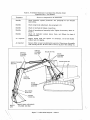
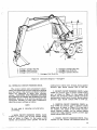
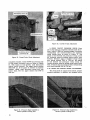
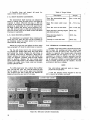
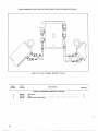
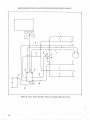
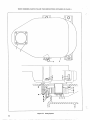
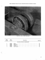
1
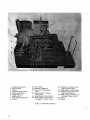
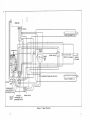
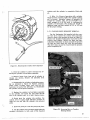
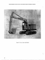
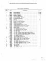
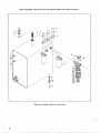
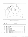
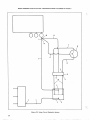
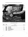
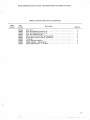
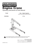
BULLETIN CED-26
Price $4.00
PRINTED IN U.S.A.
•3013.1:a
'CORPORATION
CONSTRUCTION EQUIPMENT DIVISION
WAUKESHA, WISCONSIN 53187
BULLETIN CED-26
service manual
HYDRAULIC EXCAVATORS
model
serial no.
This manual contains operating instructions, service information, and
repair parts lists for all models unless otherwise noted.
Almost half a century of design and manufacturing experience has gone into your new
Mein-Werner machine. It is the finest equipment that this know-how and modern
technology can produce. We congratulate you on your selection.
We recommend that you become familiar with this manual and the maintenance procedures outlined herein. Following these instructions and operating the machine in a
proper manner will assure you of long, dependable and profitable service.
cORPORATION
CONSTRUCTION EQUIPMENT
DIVISION
WAUKESHA, WISCQNSIN 53187
INSTRUCTIONS FOR ORDERING REPLACEMENT PARTS
To assure prompt and accurate service, include the following data
with each parts order:
1.
2.
3.
4.
5.
6.
7.
Model and Serial number of machine '
Part numbers
Part descriptions
Quantity of each part desired
Correct shipping destination
Method of transportation
Engine Serial number
Confirm all telephone and telegraph orders in writing. Be sure these
orders are marked "Confirmation," to avoid duplication of orders.
WHERE TO ORDER PARTS
Hein-Werner Dealers are conveniently located throughout the United
States and Canada. These Dealers maintain a stock of genuine HeinWerner replacement parts. Always order parts from your nearest
Hein-Werner Dealer.
INSPECTION OF SHIPMENTS
Carefully inspect all shipments upon arrival. In the event of loss or
damage, do not accept the shipment until the transportation company
either makes a notation on the freight bill, or gives you an inspection
report covering said damage or loss. In the event of concealed damage
or loss, notify the carrier at once (within 20 days) requesting that an
inspection be made and damage or loss be acknowledged.
ADJUSTMENTS AND RETURNS
Refer to the written Warranty in this manual for an explanation of
Warranty policy. If you feel a Warranty claim is in order, consult your
Dealer. Claims must be made through your Dealer within a 15 day period
from the time a failure occurs. Parts returned directly to the factory,
without Dealer Authorization, will not be accepted.
USE ONLY GENUINE HEIN-WERNER PARTS FOR MAXIMUM PERFORMANCE
ii
TABLE OF CONTENTS
Page
SECTION I - DESCRIPTION
1-1. Hydraulic Circuits and Controls
1-2. Carrier
1-3. Accessories
1
1
4
4
SECTION II - OPERATION
2-1. Preparation for Use
2-2. Initial Checks
2-3. Starting the Engine
2-4. Operating Controls
2-5. Digging Hints
2-6. Stopping the Engine
2-7. Preparation for Storage
5
5
5
5
5
8
8
8
SECTION III - MAINTENANCE AND 'REPAIR
. .
3-1. Preventive Maintenance
3-2. Lubricant Recommendations
. . ............ . ..
3-3. Maintenance Schedules ....
3-4. Lubrication - Upperstructure
. •
3-5., Lubrication - Crawler
3-6. Lubrication - Carrier
3-7. Propel Drive Chain Adjustment
3-8. Crawler Track Adjustment
3-9. Hydraulic Circuit Pressure Checks
3-10. Swing and Propel Brake Adjustment
'3-11. Tool Kits
3-12. Gear Box Removal
3-13. Propel and Swing Gear Box Repair
. . .
3-14. Shaft Bearing Adjustment
3-15. Gear Box Replacement
3-16. Hydraulic Cylinder Repair
3-17. Crawler Drive Sprocket Removal
3-18. Tumbler or Idler Shaft Bushing, Thrust Washer and Seal
Replacement
SECTION IV - REPAIR PARTS LIST
9
9
9 .
9
12
12
12
12
12
13
14
15
15
16
18
18
18
20
20
21
iii
1.
2.
3.
4.
5.
6.
7.
8.
9.
Hydraulic Reservoir
Return Lines
Filters
Hydraulic Swing Motor
House Brake Drum
Swing Gear Box
Hydra-Swivel
Ball Bearing Ring Gear
Levers
10. Foot Pedals
11. Machinery Platform
12. Pressure Compensating
Unit
13. Inline Pressure Compensating Unit
14. Swing System Control Valve
15. Boom, Bucket, and Propel or
Outrigger Control Valve
Figure 1. Machinery Platform
iv
16. Dipstick and Propel or Outrigger Control Valve
17. Swing System, Pump System
18. Dipstick and Propel or Outrigger Pump Section
19. Boom, Bucket, and Propel or
Outrigger Pump Section
20. Clutch
21. Engine
SECTION I
DESCRIPTION
1-1. HYDRAULIC CIRCUITS AND CONTROLS.
The information in this section is designed to
furnish the owner and operator of Hein-Werner
excavators with the basic information needed to understand the operation of the machine. An understanding
of the various systems is essential to proper operation and service, and we suggest this description be
read thoroughly.
Power for the unit is supplied by either a gasoline or diesel engine (21, Figure 1) the make of which
is optional. (For service parts and information,
refer to the engine manual supplied with your machine.)
The engine is coupled to the hydraulic pump by
either a direct drive shaft or a clutch (20). The
clutch is extremely useful as a starting aid in cold
weather. (If your machine is equipped with a clutch,
refer to the separate section included with this manual.
The pump is a gear type, with three sections
in tandem, mounted directly to the engine clutch
housing. Each pump section is fitted with a separate
supply line from the reservoir to assure proper
oil flow. The pump section (19) closest to the engine
delivers power to the boom, bucket, and propel
control valve (15) on the crawler mounted machine,
and to the boom, bucket, and outrigger system on
the carrier mounted machine. The center pump section
(18) supplies power to the dipstick and propel circuit
valve (16) on the crawler mounted machine and to the
dipstick and outrigger system on the carrier mounted
machine. The pump section (17) furthest from the
engine delivers power to operate the swing circuit
on all models. The three pump sections are completely
independent of each other enabling simultaneous use
of all three circuits.
The oil flows from the pump to the three control
valves. When the control valves are in a neutral position, the oil flows without restriction through the
control valve and return lines (2) to the filters (3)
which are mounted on the hydraulic reservoir (1).
Each circuit is equipped with a filter which contains a cleanable filtering element. Disposable elements also are available as a replacement part.
After being filtered, the oil flows directly into the
reservoir.
The control valves are operated by levers (9)
and foot pedals (10) in the operator's cab. The cab
is also equipped with a complete set of engine
gages and controls. The engine gage set consists
of an ammeter, individual gages for fuel level,
oil pressure and water temperature, and a combination tachometer and engine revolution hour meter.
When a typical cylinder circuit is put into operation
by moving the control lever or foot pedal in either
direction from the neutral position, the valve spool
moves within the control valve. This spool reroutes
the oil flow from the return line port to the port
which supplies oil to the cylinder being used. This
spool is spring-loaded to return to neutral position
when the control lever or pedal is released. The
control valves have excellent "feathering" characteristics to assure smooth and precise operation
of all components. The control valves contain a
relief valve which is adjusted at the factory to a
specified limit. If the pressure demanded by the
circuit being used exceeds this pre-set limit, the
relief valve will bypass the oil to the reservoir
until the pressure demanded by the circuit drops
to the specified pressure setting. The digging members are also protected from overload by an inline
pressure compensating unit (13). This unit relieves
the pressure in the boom and dipstick circuits when
external forces cause the pressure to exceed the
maximum allowable. The swing circuit is controlled
by the single spool control valve (14). This valve
and its built-in relief valve are identical in design
and purpose to the typical cylinder control valve
already described. The swing circuit is also further
protected by a pressure compensating unit (12) which
minimizes shock loads. The double rotation, positive
displacement hydraulic motor (4) provides unlimited
swing in either direction.
The motor is directly coupled to the swing gear
box (6) which is mounted to the machinery platform
(11) with specially ground alloy steel studs. This
mounting assures perfect mesh between the output
pinion and the ball bearing ring gear at all times.
All gears and shafts in the swing system are precision machined and hardened to give maximum life.
The shafts are carried by tapered roller bearings.
The cover and case are precision bored and milled
to assure precise gear mesh.
The use of a double row ball bearing ring gear (8)
results in reduced maintenance, smoother rotation,
and longer life. The bearing requires no day-to-day
maintenance other than lubrication.
The crawler propel control valve is essentially
the same as the other control valves except for
an added "detent" feature. This "detent" mechanism
holds the valve spool in either position to allow
the operator to perform other operations while traveling. The control levers must be manually returned
to the neutral position to stop the crawler travel.
When the propel circuit is in operation, the oil
flows from the control valve, through the hydraswivel (7) to the propel motors. The hydra-swivel
is used on both the carrier and the crawler mounted
machines. Its purpose is to allow oil to flow from
the upper structure to the propel motor or the
outrigger cylinders which are located on the nonrotating portion on the machine. This is accomplished
1
RESERVOIR
0
BOOM CYLINDER L. H
INLINE
RELIEF
SW ING
I
A\■ F?
0\1
BOX
HYDRA-SWIVEL
•
Ai
DIPSTICK CYLINDER
BUCKET
CYLINDER
L
wzr
,
11
Ail Are/
CLUTCH
i
ii
PUMP
'
0 0
HPRESSURE COMPENSATING UNIT
BOOM CYLINDER R. H.
P1V—rj
lir • -
BOOM BUCKET
AND PROPEL OR.
OUTRIGGER VALVE
DIPSTICK
INLINE AND PROPEL OR
RELIEF OUTRIGGER VALVE
SWING VALVE
Figure 2. Upper Circuitry
PRESSURE COMPENSATING
UNIT
PROPEL
MOTOR
FRONT OF
MACHINE
HYDRA SWIVEL ASSEMBLY
FORWARD TRAVEL
PRESSURE HOSES
DRAIN HOSE
PRESSURE COMPENSATING
UNIT
Figure 3. Lower Circuitry, Crawler
u.
PROPEL
MOTOR
HYDRA-SWIVEL
ASSEMBLY
OUTRIGGER
CYLINDER
OUTRIGGER
CYLINDER
LOOKING TOWARD
FRONT OF CARRIER
Figure 4. Lower Circuitry, Carrier
by the use of a series of ported grooves which
are sealed with "0" rings.
The two propel motors are mounted directly to
the propel gear boxes. Each track of the crawler
is driven by a separate motor and gear box. This
independent drive results in greatly increased maneuverability.
1-2. CARRIER
The standard Hein-Werner Carrier is of rugged
job-proven design. The carrier can be equipped with
a remote control unit which enables the operator to
steer, shift, brake, and accelerate the carrier from
within the excavator cab.
1-3. ACCESSORIES
The crawler track assemblies and carbody are
designed for long trouble-free service. The carbody
and side frames are rugged, steel fabrications which
are reinforced at all points of stress concentration.
The components of the track assemblies such as the
track shoes, tumblers, idlers, rollers, and sprockets,
are made from high grade heat treated alloy steel
with excellent durability characteristics. These parts
are designed to provide good dirt shedding qualities.
The 20 track rollers are equipped with pre-greased
ball bearings with armor shields to protect the seal
from dirt, branches, and other foreign matter. The
use of these bearings also results in reduced dayto-day maintenances of the track assembly.
4
Accessories include a log grapple, a clam shell
bucket, frost point, and a special 60" ditch cleaning
bucket. Various standard buckets are also available.
These buckets range in size from 16" to 48" widths.
If your machine is equipped with any of the above
mentioned accessories, refer to the special section
in this manual for service and parts information.
The following basic schematics will be useful in
tracing the hydraulic circuitry:
1. Upper circuitry (Figure 2).
2. Lower circuitry, crawler (Figure 3).
3. Lower circuitry, carrier (Figure 4).
SECTION II
OPERATION
2-1. PREPARATION FOR USE.
Before operating the machine, make the following
checks and adjustments:
ALL MODELS
1. Engine checks (see engine manual for detailed
instructions).
a. Crankcase oil level.
b. Fan belt tension.
c. Coolant level.
d. Air cleaner.
b. Block up the machine and release pressure
on the boom.
c. Remove the four locking bolts. Attach a
chain to the side frame and the bucket.
Use the bucket to pull the tracks out until
the side frame is flush with the cross tube.
d. Replace and tighten the locking bolts in
the second set of holes. Extend the opposite
track in a similar manner. Each track will
move out four inches to give 104 inch
overall width.
2-2. INITIAL CHECKS.
SWING BEARING
e. Level of electrolyte in battery.
f. Battery and terminals for corrosion.
g. Tightness of mounting bolts.
h. Fuel level.
2. Upperstructure checks.
a. Security of fuel, oil, and electrical connections.
b. Freedom of operation of all controls.
c. Oil level in hydraulic reservoir. Remove
the high level plug and check that the oil
level is between the high level plug and
the low level plug. If necessary, add premium grade SAE 20 oil.
d. Damage which may have occurred in shipment.
e. Level of lubricant in gear boxes. If necessary, add EP 80-90 oil.
f. Lubricate entire machine as required; see
paragraphs 3-4,3-5, and 3-6.
After six to eight hours of running time, check
the swing bearing mounting bolts for tightness. Torque
the bolts to 2400 inch pounds.
CYLINDERS
After four to eight hours of initial operation,
tighten the hydraulic cylinder packing nuts to prevent excessive escape of hydraulic oil around the
cylinder rods. Tighten the nuts until they are snug
and then back them off 1/4 to 1/2 turn. Do not
overtighten; a small seepage of oil at these points
is necessary for cylinder rod lubri?ation.
2-3. STARTING THE ENGINE.
Leave all control levers in neutral. Place throttle
in approximately half-fuel position. Place ON-OFF
switch in ON position or place fuel shut-off lever
in RUN position. Depress starter button to crank
engine. If engine fails to start after two or three
attempts, refer to engine manual for cause of trouble
and instructions to correct it.
2-4. OPERATING CONTROLS (See Figure 6).
CRAWLER MODELS
1. Carbody and side frame assembly checks.
a. Tightness of all mounting bolts, see Table 4.
b. Track adjustment, see paragraph 3-8.
c. Drive chain adjustment, see paragraph 3-7.
2. When the crawler-mounted machines are shipped from the factory, they are assembled to the
legal 96-inch shipping width. They may be operated
at this width or extended to 104 inch width for greater
stability. To extend the tracks, proceed as follows:
a. Swing the boom (see Figure 5) over the
side of the tracks and with the bucket
tucked, apply down pressure with the boom
to lift the track off the ground.
Operators not familiar with hydraulic machines
may tend to over-control and thereby cause rough
operation of the machine. It is recommended that
the machine be operated at half throttle or less until
the operator gets the "feel" of the controls. The
throttle setting may then be gradually increased to
fully governed speed. The operation of each control
is as follows:
BOOM CONTROL LEVER
1. To raise boom, pull boom control lever back.
2. To hold boom in position, move control lever
to center position (neutral).
3. To lower boom, push boom control lever
forward.
Figure 5. Extending Crawler Tracks
BUCKET CONTROL PEDAL OR LEVER
1. For normal operation, use the foot pedal to
control the bucket. However, for very close work
when speed is not a factor, use the lever to control
critical movement of bucket.
4. To open dipstick, push down with toe of the
right foot on the pedal or push the control lever
forward.
SWING CONTROL LEVER
2. To place bucket in closed position, push down
with heel of left foot on the pedal or pull the lever back.
1. To swing platform in a clockwise direction,
push lever forward.
3. To hold bucket in position, move the pedal or
lever to center position (neutral).
2. To swing platform counterclockwise, pull lever
back.
4. To place bucket in open position, push down
with toe of left foot on the pedal or push the lever
forward.
The swing of the platform is controlled by reversing the control lever. Slight overcontrol allows the
machine to be operated with a high degree of smoothness with no abrupt or dead stops. For example,
if the machine is rotating clockwise (lever pushed
forward), feather the lever back toward the operator
until the rotation stops. If one particular position
is desired, lock the platform in place with the
swing brake control lever.
DIPSTICK PEDAL OR LEVER
1. For normal operation, use the foot pedal to
control the dipstick. However, for very close work
when speed is not a factor, use the lever to control
critical movement of dipstick.
SWING BRAKE OR PROPEL BRAKE LEVER
2. To tuck dipstick in, push down with heel of
right foot on the pedal or pull the lever back.
3. To hold dipstick in place, move the pedal or
lever to center position (neutral).
6
1. To engage brake, pull up on the lever. The
lever will snap into an overcenter loch position.
2. To release brake, push the lever down.
PROPEL OR OUTRIGGER CONTROL LEVERS
PROPEL LEVERS
When in the normal traveling position (drive
sprockets to the rear), follow the instructions below.
When in reversed position (drive sprockets to the
front), reverse all directional instructions. The speed
of travel is governed by the engine speed.
1. To propel machine forward, push both levers
forward.
2. To propel machine backward, pull both levers
back.
3. To make a right hand turn, use any of the
following procedures:
a. Push the left lever forward and leave
the right lever in neutral.
b. Pull the right lever back and leave the
left lever in neutral.
c. When working in close quarters, or when
speed is required, a right hand "spin" turn
may be made by simultaneously pushing
the left hand lever forward, and the right
hand lever back.
4. To make a left hand turn, reverse the above
directions.
OUTRIGGER LEVERS
1. To set outriggers, push both levers forward.
2. To raise outriggers, pull both levers back.
When in the digging position (boom extended over
the rear of the carrier), the left outrigger is controlled by the left lever.
STARTER
BUTTON
BOOM CONTROL LEVER
INSTRUMENT PANEL
DIPSTICK CONTROL LEVER
CHOKE LEVER
THROTTLE LEVER
EMERGENCY STOP KNOB
PROPEL
CONTROL
LEVERS
(CRAWLER)
SWING CONTROL. LEVER
BUCKET CONTROL LEVER
PROPEL
BRAKE
CONTROL
LEVER
(CRAWLER)
OUTRIGGER
CONTROL
LEVERS
(TRUCK)
HEIGHT ADJUSTMENT
SWING BRAKE
CONTROL LEVER
DIPSTICK
CONTROL
PEDAL
BUCKET
CONTROL
PEDAL
Figure 6. Operating Controls
SEAT ADJUSTMENT CONTROLS
The seat height can be adjusted by pulling out
the height adjustment pin, setting the seat to the
desired height and then reinserting the pin.
The seat can be moved forward and backward
by pulling out the pin under the seat, sliding the seat
cushion to the desired position and then reinserting
the pin.
2-5. DIGGING HINTS.
1. Keep the machine as close to the work as possible. This results in a greater mechanical advantage
and also cuts down the cycle time. Start a cut with
the dipstick at right angles to the boom point; this
will decrease cycle time because the boom does not
have to be repositioned as often.
2. Tuck in the dipstick as the boom is raised
out of a cut; this will permit clearing the top of the
cut sooner and reduce the cycle time. Square cuts
for manholes, etc., can be made easier by moving
the machine in line with each bank, rather than
using the swing to get from bank to bank.
3. Make straight down end cuts by extending the
dipstick and bucket and moving the machine forward or
back to reach the bottom of the cut. To decrease
cycle time, especially in a deep cut, shave off a
layer at a time, rather than going to the bottom of
the cut on every cycle. Rocks and stumps can be
uncovered, undermined, and pried out using the
bucket.
4. For faster dumping, open both the bucket and
the dipstick. When digging in gravel, stones, or shale,
use the bucket teeth to loosen the material so that
the bucket can be filled on the next cycle. When
digging in clay or hard soil, use the bucket in a
flat position and shave or peel the soil by moving
the boom and dipstick. The bucket can be removed and
reattached in an inverted position to use the machine
for shovel operation.
2-6. STOPPING THE ENGINE.
gency, stop knob located on back wall of cab. This
will shut off the air supply to the engine by tripping
the air shut-off valve. If air shut-off valve has been
tripped, it must be reset before the engine will
operate. To reset the air shut-off valve, first push
the emergency stop knob all the way in, and then
manually reset the air shut-off valve latch. Refer
to the engine manual for detailed instructions.
2-7. PREPARATION FOR STORAGE.
If the machine is to be stored for an indefinite
length of time, perform the following procedures,
subject to the length of the anticipated storage
period:
1. Drain fuel system and refill with Valvoline
Oil Company "Tectyl 503-C" rust preventative compound or its equivalent.
2. Drain engine lubricant and refill with engine
preservative oil.
3. Drain engine cooling system and refill with
corrosion inhibitor.
4. Crank engine to circulate preservative oils
through fuel and lubricating systems.
5. Drain lubricant from swing and propel gear
boxes and refill with preservative oil.
Wherever fluid systems have been drained,
attach a waterproof tag to the tank or engine,
to warn the operator not to operate the
machine until the system(s) have been drained
and refilled with correct fluid.
6. Remove battery.
7. Relieve engine belt tension. Tag the belts
to indicate that belt tension must be adjusted before
starting engine.
1. Reduce engine speed to idle. Allow engine to
operate at idle speed for approximately five minutes
to normalize engine temperature, then place the
ON-OFF switch or fuel shut off lever in OFF position.
Do not stop the engine suddenly unless it is absolutely
necessary.
8. Wipe machine to remove all film and dirt.
Apply preservative to any exposed metal surfaces
subject to corrosion through prolonged non-usage,
such as valve spools, cylinder rods, etc.
2. If the engine continues to run after the fuel
shut-off lever is placed in OFF position, pull emer-
10. Fill hydraulic system completely with hydraulic
oil.
9. Close and secure all doors. Seal all openings
with waterproof paper.
SECTION III
MAINTENANCE AND REPAIR
3-1. PREVENTIVE MAINTENANCE.
3-2. LUBRICANT RECOMMENDATIONS.
It is impossible to overstress the importance of
preventive maintenance. A well organized, day-to-day
preventive maintenance schedule will save you expensive "downtime" and costly repairs. In addition
it will help to insure proper operation and extended
life of the machine.
To insure maximum efficiency and long life, use
the lubricants recommended in Table 1 or their
equivalent.
This section outlines suggested maintenance schedules, lubrication guides, and minor adjustments which
should be made to maintain optimum performance
from your machine. These schedules, and the preventive maintenance record sheets included with
this manual, will help you organize a good system
of daily care which best suits your particular operation.
The maintenance requirements listed are for average working conditions. If your machine is subject
to adverse conditions, such as extreme dust, moisture, etc., the frequency and extent of the maintenance
precedures should be increased accordingly.
A one year supply of "Preventive Maintenance
Record" forms is included at the end of this manual.
A sample copy, with several typical entries made,
has also been included to show how these records
may be maintained. These records, when kept complete and up-to-date, will benefit both the owner
and the operator.
3-3. MAINTENANCE SCHEDULES.
Follow the maintenance schedules and procedures
as outlined in Tables 2 and 3.
Table 1. Recommended Lubricants
Part
Lubricant
Gear Boxes
EP 80-90 oil
Open Gears
Crater compound
Swing bearing
(4 fittings)
Mobilux GR #2 or
equivalent.
Gear box bearing
grease fittings
Mobil No. 5 grease,
or equivalent.
All other grease
fittings
Moly type grease,
such as Mobiloil
special or equivalent.
Hydraulic reservoir
Premium grade SAE
20 oil.
Table 2. Preventive Maintenance and Inspection Schedule
(Upperstructure - All Models)
Frequency
Service or Inspection to be Performed
Daily
Lubricate as required. See paragraph 3-4.
Daily
Inspect for and correct any fuel, oil, coolant, or hydraulic system leaks.
Daily
Check oil level in swing gear box. If necessary, add oil as specified
in Table 1.
Daily
Check oil in hydraulic reservoir. If necessary, add oil as specified
in Table 1.
Daily
Check back pressure indication of filter gages. If gage registers in
"red zone," clean or replace filter element.
Daily
Check engine for: crankcase oil level, coolant level, engine belt
tension; and level of electrolyte in battery(s). (See engine manual for
complete specifications.)
Weekly
Check swing bearing mounting bolt torque; tighten to 2400 inch pounds
if necessary.
Table 2. Preventive Maintenance and Inspection Schedule (Cont)
(Upperstructure - All Models)
Frequency
Service or Inspection to be Performed
Monthly
Check hydraulic system pressures. See paragraph 3-9 for detailed
instructions.
Monthly
Check swing brake adjustment. See paragraph 3-10.
Monthly
Check all mechanical linkage connections.
Monthly
Check all mounting and assembly bolts. Tighten if necessary. Refer to
Table 4.
Monthly
Check all hydraulic system hoses, lines, and fittings for signs of
possible trouble.
As
Inspect bucket teeth and replace as necessary. Do not use shanks
without teeth for digging.
required
As required
Remove filter screen from hydraulic reservoir. Clean screen thoroughly
with cleaning solvent. Be sure filter screen is in place when adding oil.
DIPSTICK
CYLINDER
BASE PIN
DIPSTICK
CYLINDER
ROD PIN
BOOM LIFT PIN
BOOM
CYLINDERS
ROD END
:-.7
7- 77 7:71
_
- -1-. I
BUCKET CYLINDER
BASE PIN
I
11
11
11
II
11
11
I,
I
I ■ ........ I I
I
I
I
I
I
BOOM PIVOT PIN
III
I
I
121,
ip"
........1 -- '''l
DIPSTICK
PIVOT PIN
.... --- --•-- -1
BOOM
CYLINDERS
BASE END
1I
'II...L.-a,
—— — 1
: r - r ‘......._-,...-,
Jo,
111---11:2--1::;:zrj-:"1 4
---,..:—..1. ----IC
. —._._I1_-1111i ii: 0I'
BELL CRANK
PIVOT PIN
BUCKET
PIVOT PIN
BUCKET
LINK
BUCKET LINK AND BUCKET
CYLINDER ROD END
Figure 7. Lubrication Diagram — Sheet 1
,
,
i
*4w'1
Phi
--r
. . ,/i,Ili
Table 3. Preventive Maintenance and Inspection Schedule - Crawler
Frequency
Service or Inspection to be Performed
Daily
Check level of lubricant in propel box. See paragraph 3-15.
Daily
Lubricate as required. See paragraph 3-5.
Weekly
Check propel drive chain adjustment. See paragraph 3-7.
Weekly
Check crawler track adjustment. See paragraph 3-8.
Monthly
Check propel brake adjustment. See paragraph 3-10.
Monthly
Check all mounting and assembly bolts. Tighten if necessary. Refer to
Table 4.
Monthly
Check all mechanical linkage connections.
Monthly
Check all hydraulic system hoses, lines,
possible trouble.
and fittings for signs of
PUMP DRIVE
BEAR ING
INTERMEDIATE
SHAFT
OUTPUT
SHAFT
SWING
CLUTCH
GEAR
CONTROL
LEVER
F ITTINGS
(4)
• mCiPi'i..;:gv...T.1*'..W•gi:;1.,:17..,3:•:1015•4•Vr•W•1',. 34!::,.:F47...
CROSS
SHAFT
CONTROL
LEVER
FITTINGS (2)
Figure 8. Lubrication Diagram — Upperstructure, Sheet 2
.
11
PROPEL GEAR
BOX FITTINGS
SWING BEARING
FITTINGS (4)
RH IDLER SHAFT
FITTINGS (2)
RH TUMBLER SHAFT
FITTINGS (2)
LH IDLER SHAFT
FITTINGS (2)
LH TUMBLER SHAFT
FITTINGS (2)
Figure 9. Lubrication Diagram — Crawler
3-4. LUBRICATION - UPPERSTRUCTURE.
Lubricate the upperstructure at the points shown
in Figures 7 and 8. Always remove excess grease
after lubrication, or dirt and dust will accumulate
and work into bearings and bushings.
2. Loosen the four adjusting bolt lock nuts and
tighten both adjusting bolts equally to adjust chain
until deflection is 3/4" to 1".
3. Tighten lock nuts and gear box mounting bolts
and recheck deflection.
3-5. LUBRICATION - CRAWLER.
3-8. CRAWLER TRACK ADJUSTMENT.
Lubricate the crawler assembly at the points
specified in Figure 9. Be sure to lubricate crawler
daily, even though the machine has not been traveling, since there is movement when swinging and
digging. DO NOT lubricate propel drive chain.
The crawler tracks should be adjusted until some
slack exists. When there is no slack, or excessive
slack, adjust the tracks at the idler end of the side
frame (Figure 12) as follows:
3-6. LUBRICATION - CARRIER AND OUTRIGGERS.
1. Remove shim cover plate.
2. Insert Hein-Werner Pushmaster unit, supplied
with tool :kit, as shown.
Lubricate carrier as specified in the carrier
manual shipped with your machine. Lubricate the
outriggers at the points indicated in Figure 10.
3. Turn the relief knob clockwise, and "jack"
out the idler bearing block until correct slack exists.
3-7. PROPEL DRIVE CHAIN ADJUSTMENT.
5. Release the pressure on the Pushmaster Unit
by turning relief valve knob counterclockwise.
Check propel drive chain for 3/4" to 1" deflection
on the slack side of chain. If necessary to adjust,
proceed as follows:
1. Loosen the four propel box mounting bolts
(Figure 11) which attach gear box to side frame.
12
4. Install the 1/4" and 1/8" thick shims (furnished
in the tool kit) as required to take up play.
6. Replace the shim cover plate.
This adjustment must be performed on both
the inside and the outside of the side frame. The
two idler bearing blocks must be adjusted equally
to keep the idler from becoming "cocked."
1. Outrigger Cylinder Rod Pin
2. Outrigger Foot Pivot Pin
3. Outrigger Arm Pivot Pin
7
4. Outrigger Cylinder Base Pin
5. Outrigger Arm Pivot Pin
6. Outrigger Cylinder Rod Pin
Outrigger Foot Pivot Pin
Figure 10. Lubrication Diagram — Outriggers
3-9. HYDRAULIC CIRCUIT PRESSURE CHECK.
The correct control valve and pressure compensating unit adjustments have been made before shipping
from the factory. Only factory and dealer representatives are authorized to adjust valve pressure
settings. TAMPERING WITH PRESSURE SETTINGS
WILL RESULT IN VOIDING THE WARRANTY OF THE
MACHINE. However, at the intervals specified in the
maintenance schedule, or in the event of malfunction,
check the pressure settings as follows:
NOTE
Be sure gage is indicating correctly before
proceeding.
1. BOOM CIRCUIT PRESSURE CHECK. Install
0-3000 psi pressure gage in boom cylinder testing
port as shown in Figure 13. Run engine at full
throttle and pressurize boom cylinder rod end by
pushing boom control lever forward. Boom cylinder
pressure gage should indicate 1850 to 1900 psi.
2. BUCKET CIRCUIT PRESSURE CHECK. Install
0-3000 psi pressure gage in bucket cylinder testing
port as shown in Figure 14. Run engine at full
throttle and pressurize bucket cylinder rod end by
pushing bucket control lever forward. Bucket cylinder
pressure gage should indicate 2050 to 2100 psi.
3. DIPSTICK CIRCUIT PRESSURE CHECK. Install 0-3000 psi pressure gage in dipstick cylinder
testing port as shown in Figure 15 at base end of
the cylinder. Run engine at full throttle and pressurize dipstick cylinder rod by pulling dipstick
control lever back. Dipstick cylinder pressure gage
should indicate 2050-2100 psi.
4. PROPEL CIRCUIT PRESSURE CHECK. Place
machine so that forward and backward travel are
13
MOUNTING BOLTS (4)
PUSHMASTER UNIT
1
ADJUSTING BOLTS
Figure 12. Crawler Track Adjustment
ADJUSTING BOLTS
LOCK NUTS (4)
Figure 11. Propel Drive Chain Adjustment
completely blocked. Install 0-3000 psi pressure gage
in each propel crossover valve as shown in Figure
16. With engine at full throttle, push both propel
control levers forward. The gages should indicate
2050-2100 psi. If the gages do indicate no pressure
reading, repeat same procedure except pull both
levers back. The two gages should read 2050 to
2100 psi.
Figure 13. Pressure Gage Installed in
Boom Cylinder Testing Port
14
5. SWING CIRCUIT PRESSURE CHECK. Place
unit so that swing is completely blocked in both directions. Install 0-3000 psi pressure gages in pressure
compensating unit counterclockwise and clockwise
swing testing ports as shown in Figure 1'7. Run
engine at full throttle and pressurize swing circuit
for clockwise swing by pushing swing control lever
forward. Pressure gage in clockwise swing testing
port should indicate 1650 to 1700 psi. Run engine
at full throttle and pressurize swing circuit for
counterclockwise swing by pulling swing control lever
back. Pressure gage in counterclockwise swing testing
port should indicate 1650 to 1700 psi.
3-10. SWING AND PROPEL BRAKE ADJUSTMENT.
The swing brake is common to all models. Crawler
mounted machines, in addition, are equipped with a
Figure 14. Pressure Gage Installed in
Bucket Cylinder Testing Port
Figure 15. Pressure Gage Installed in
Dipstick Cylinder Testing Port
Figure 16. Pressure Gage Installed in
Propel Circuit Cross-over Relief Valve
brake on each propel gear box. The adjusting procedures are identical for both propel and swing brake
assemblies.
The brakes can be adjusted at three points:
1. In the handle itself.
2. At either end of the conduit.
3. At the gear box connection.
The swing, and propel, brake is a static brake
only. Therefore, the amount of wear should be very
small. However, if the brakes do need adjusting,
proceed as follows:
and block the machine as described in paragraph
2-1 and Figure 5. Disconnect the hydraulic lines
from the propel motor, remove the brake cable
and mounting bracket from the gear box. Disconnect
the four locking bolts which attach the side frame to
the carbody cross tubes. Attach chain as shown in
Figure 5 and pull the entire side frame off. The
side frame assembly can now be tipped flat to
facilitate the removal of the drive chain and gear
box. The swing gear box is easily removed by unscrewing the four retaining nuts and lifting off the
gear box.
1. Make the initial adjustment in the handle itself,
by turning the knurled adjusting .knob at the tip of
the handle until the handle "snaps" into an overcenter
lock position when pulled up.
2. If for some reason the adjustment can not
sufficiently be made in the handle, make the remaining
adjustment at either of the other two points.
3-11. TOOL KITS.
The tool kit for the carrier mounted machines
(Figure 18) includes the tools necessary for all
maintenance and adjustments of the upperstructure.
The tool kit supplied with crawler mounted
machines (Figure 19) includes the tools for the upperstructure plus the extra tools necessary for adjustments and maintenance of the crawler. This kit also
includes shims and groove pins for the crawler
tracks.
3-12. GEAR BOX REMOVAL.
To remove the propel gear box, swing the boom
over the side frame which is to be removed. Disconnect the safety chain from the carbody. Raise
Figure 17. Pressure. Gage Installed in Swing Circuit
Pressure Compensating Unit Testing Port
15
1. Grease Gun
2. Spanner Wrench - Cylinder Heads
3. Open End Wrench, 7/8" and 1"
4. Open End Wrench, 1-1/4"
5. Universal Joint, 3/4" Drive
6 Socket, 1-1/16", Deep Throat 3/4" Drive
7. Socket, 1-1/8", Deep Throat 3/4" Drive
8. Socket, 15/16", Standard 3/4" Drive
9. Extension, 12", 3/4" Drive
10.
11.
12.
13.
14.
15.
16.
17.
18.
Crescent Wrench, 15"
Special Tube Wrench, 1-1/2"
Sliding "T" Handle, 3/4" Drive
Open End Wrench, 3/8"
Drain Valve Handle - Oil Reservoir
Plugs, 1-1/4" - Supply Lines (2)
Plug, 1" - Supply Lines
Tool Box
Tee Handle - Machinery Housing Doors
Figure 18. Tool Kit — Carrier Mounted Machine
3-13. PROPEL AND SWING GEAR BOX REPAIR.
The gear boxes are of relatively simple construction and therefore detailed disassembly and repair
instructions are not necessary. However, for ease of
disassembly and repair, and also to guard against
unnecessary damage to the gear box components, we
recommend that the following list of general hints
and precautions be followed:
16
1. Use a soft hammer when assembling or disassembling any parts which may become nicked or
marred.
NOTE
2. Use a press wherever possible to remove and
replace gears and bearings.
3. Use care when removing seals and bearing
cups to avoid damaging the case, or cover, in which
the components are seated.
4. Replace hex nuts and bolts with rounded corners, all lockwashers, oil seals and gaskets.
Use only genuine Hein-Werner parts to insure
proper fit and operation.
5. Clean the threads of all bolts, studs, and nuts
to assure proper torque and adjustment.
Upperstructure Tools
1.
2.
3.
4.
5.
6.
7.
8.
9.
Grease Gun
Spanner Wrench - Cylinder Heads
Open End Wrench, 7/8" and 1"
Open End Wrench, 1-1/4"
Universal Joint, 3/4" Drive
Socket, 1-1/16", Deep Throat 3/4" Drive
Socket, 1-1/8", Deep Throat 3/4" Drive
Socket, 15/16", Standard 3/4" Drive
Extension, 12", 3/4" Drive
10.
11.
12.
13.
14.
15.
16.
17.
18.
Crescent Wrench, 15"
Tube Wrench, 1-1/2" Special
Sliding "T" Handle, 3/4" Drive
Open End Wrench, 3/8"
Drain Valve Handle - Oil Reservoir
Plugs, 1-1/4" - Supply Lines (3)
Plug, 1" - Supply Lines
Tool Box
Tee Handle - Machinery Housing Doors
Crawler Tools
Cl. Hein-Werner Pushmaster Unit - Track Adjustment
C2. Chain Adapter - Sprocket Removal
C3. Track Adjusting Shims, 1/4" (16)
C4. Track Adjusting Shims, 1/8" (20)
C5. Socket, 1-5/16", Standard 3/4" Drive
C6. Track Shoe Groove Pins (6)
Figure 19. Tool Kit — Crawler Mounted Machine
17
6. Carefully clean and inspect all parts for
signs of wear or future failure.
Table 4. Torque Values
Description
Torque
3-14. SHAFT BEARING ADJUSTMENT.
The intermediate shaft bearings are adjusted by
means of shims under the shaft cover. Use shims as
required to obtain .002 inch end play, to .002 inch
preload on the bearing. The output shaft bearings are
adjusted by positioning the nut on the upper end of
the shaft. Tighten and secure nut as required to obtain .002 inch end play to .002 inch bearing preload.
Pack the grease cavity of the shaft covers with Mobil
#5 grease or equivalent.
3-15. GEAR BOX REPLACEMENT.
No adjustment is necessary when replacing the
swing gear box. When the gear box is in position on
the mounting studs, the output pinion is in correct
mesh with the swing bearing.
Install the propel box and adjust the drive chain
(see paragraph 3-7) while the side frame is removed.
Tip the side frame back to the normal position
by inserting the bucket teeth below the track shoes
and tucking the bucket. Replace the side frame on
the carbody cross tube by inserting a large pipe or
timber between the bucket and the side frame and,
using the dipstick, carefully push the side frames
back in position. Replace the four locking bolts
which hold the side frame to the carbody cross tubes.
Connect the safety chain, brake cable and bracket,
and the hydraulic lines.
Gear Box intermediate shaft
cover bolts
106 - 113 ft. lbs.
Gear Box output shaft cover
bolts
69 - 73 ft. lbs.
Gear Box cover to case bolts
106 - 113 ft. lbs.
Swing bearing to bearing adapter
and platform bolts
200 ft. lbs.
Swing bearing adapter to
carbody bolts
300 ft. lbs.
Carbody to cross tube bolts
556 ft. lbs.
3-16. HYDRAULIC CYLINDER REPAIR.
Cylinder repair kits contain ram head and cylinder
rod 0-rings, rod packings and wiper, piston rings
and rod nut. Use all parts of the repair kit when a
cylinder is repaired, even though some of the parts
being replaced may not appear to be worn. It is not
necessary to remove a cylinder assembly from the
unit in order to repair it with a cylinder repair kit,
but be extremely careful to prevent the entry of any
dirt or foreign particles into the cylinder. Proceed
as follows to service a cylinder:
NOTE
To refill propel gear box, remove the top filler
plug and fill the gear box with EP 80-90 oil until
the oil begins to run out the upper level checking
plug located at the side of the gear box. Replace the
plugs and check the gear box for oil leaks.
Use only factory approved parts to insure
proper fit and operation.
1. Use the spanner wrench supplied in the tool
kit to remove the cylinder ram head.
CYLINDER TUBE ASSEMBLY
ROD NUT
ROD 0
CYLINDER ROD
HEAD 0 RING
PISTON RINGS
PISTON
WIPER SEAL
ROD PACKING SET
Figure 20. Hydraulic Cylinder Disassembly
18
cylinder until the cylinder is completely filled with
oil.
9. After 4 to 8 hours of operation with a cylinder
which has been repacked, tighten the cylinder packing
nut to prevent excessive escape of hydraulic oil
around the cylinder rods. Do not overtighten as a
small seepage of oil at this point is necessary for
cylinder rod lubrication. The packing nut should be
tightened snug, and then backed off 1/4 to 1/2 turn
for the proper setting.
3-17. CRAWLER DRIVE SPROCKET REMOVAL.
Use the Pushmaster Unit supplied with the crawler tool kit to remove the crawler drive sprocket.
Attach a chain to the sprocket as shown in Figure 21.
Replace the standard Pushmaster head with the 90 °
concave head adapter. Remove the shaft end plate.
Install the Pushmaster as shown and pull the sprocket
out until the drive chain will clear the track shoes.
The drive chain can now be removed and the sprocket
pulled completely off.
Figure 21. Removing the Crawler Drive Sprocket
SHAFT END PLATE
2. Pivot the cylinder to allow clearance for removing the cylinder rod and piston assembly.
SIDE FRAME END PLATE
3. Remove hoses from base end of cylinder to
release any suction. Remove rod assembly from
cylinder tubes.
4. Disassemble the cylinder rod and piston assembly as indicated in Figure 20. Replace packings,
piston rings, 0-rings, wiper seal, and rod nut.
Lubricate all parts with hydraulic oil. Reassemble
the cylinder rod and piston assembly.
TRACK SHOE PIN
• BEARING BLOCK
5. Replace the cylinder rod and piston assembly
in the cylinder and screw the ram head into the
end of the cylinder until it is tight. Replace hoses.
DRIVE LOCK PIN
6. Slowly pivot the cylinder into position. Use
control lever to apply slight hydraulic pressure to
align the rod end with the cylinder rod end pivot
point.
7. Insert the pivot pin. Lock the pivot pin in place.
8. Use the control levers to slowly apply hydraulic
pressure alternately to both ends of the repaired
Figure 22. Removing Idler or Tumbler
Bearing Blocks
19
3-18. TUMBLER OR IDLER SHAFT BUSHING,
THRUST WASHER, AND SEAL REPLACEMENT.
To replace the shaft bushings, thrust washers,
and seals, loosen the track by removing all adjusting
shims. (See paragraph 3-8.) To remove either the
idler or tumbler bearing blocks, remove track shoe
pin (Figure 22) by driving out first the drive lock
pin shown and then the track shoe pin from the
opposite side. If the tumbler is to be removed, the
drive chain must also be disconnected. Remove the
side frame end plate and then the tumbler or idler
and shaft assembly. Next remove the shaft, the shaft
end plate, and the bearing blocks. When replacing
bushings and seals, press the bushings in and install
the seal in a reverse position (Figure 23) to allow
the bushing to be "flushed" of dirt when being
greased.
Reassemble the thrust washers and bearingblocks
to the shaft. (See Figures 41 and 42). To adjust
the shaft end plate clearance, bolt one end plate tight.
Add shims as required to obtain .020-.030 inch total
clearance between the bearing block and the shaft
end plate. When shimming the tumbler end, place
the shims on the drive sprocket end of the shaft.
Adjust the idler at either end of the shaft. Replace the shaft and tumbler or idler assembly in
the side frame by reversing the disassembly procedure. Adjust the track as instructed in paragraph 3-8.
20
BEARING BLOCK
Figure 23. Replacing Bushings and Seals
WHEN ORDERING PARTS FOLLOW THE INSTRUCTIONS OUTLINED ON PAGE ii
SECTION IV
REPAIR PARTS LIST
When ordering parts, always give the model number, machine serial
number, and engine serial number as shown on the Serial Number Plate
(Figure 24). All part numbers preceded by an asterisk (*) in the following
lists are dealer-serviced assemblies. Contact your dealer for information concerning these parts. When ordering parts for engine drive
packages, engine mounting packages, or any other assemblies for which
part numbers are not listed, include the name of the part and the make
of the engine in addition to the above information.
•
•
/ffeaf'nePropt/
CONSTRUCTION EQUIPMENT
SER. NO.
MODEL NO.
LOT NO.
ENGINE NO.
REFER TO MANUAL FOR LUBRICATION AND OPERATING INSTRUCTIONS
HEIN - WERNER
•
CORPORATION
WAUKESHA, WISCONSIN. U.S.A.
Figure 24. Serial Number Plate
21
WHEN ORDERING PARTS FOLLOW THE INSTRUCTIONS OUTLINED ON PAGE ii
Figure 25. Boom, Bucket and Dipstick
22
WHEN ORDERING PARTS FOLLOW THE INSTRUCTIONS OUTLINED ON PAGE ii
BOOM, BUCKET AND DIPSTICK
Index
Number
1
2
3
4
7
8
9
10
11
12
13
14
15
16
17
18
19
20
Part
Number
400033
400034
400.035
210024
150003
140027
220028
220027
040100
400018
400026
110045
110045
110052
220028
210002
030039
030039
030166
210002
040098
100006
100081
100081
030022
030023
030024
030162
030162
400254
400043
220000
)-1 0210028
03003 6
030164
030164
210003
210004
040101
040102
040102
030038
030036
210027
210002
400015
Description
Bucket Tooth Point
Bucket Tooth Shank
Bucket Tooth Pin
Bucket and Linkage Pin
Bucket Link Assembly
Bell Crank Link Assembly
Bell Crank Bushing - Not Grooved
Bell Crank Bushing - Grooved
Bucket Cylinder Assembly
Lock Pin
Cotter Pin
Dipstick (C-10-1, T-10-1)
. . . . . . . . . . . .
Dipstick (C-10-1 HD, T- 10-1HD) .
Dipstick (T-12-1, C-12-1HD)
Dipstick Pivot Bushing
Bucket Cylinder Base Pin
Bucket Cylinder. Hose (C-10-1, T-10-1)
Bucket Cylinder Hose (C-10-1HD, T-10-1HD)
Bucket Cylinder Hose (T-12-1, C-12-1HD)
Dipstick Rod Pin
Dipstick Cylinder
Boom Assembly (C-10-1, T-10-1)
Boom 'Assembly (C- 10-1HD, T- 10-1HD)
Boom Assembly (T-12-1, C-12-1HD)
Boom Tube - Outer
Boom Tube - Inner
Boom Tube - To Bucket Cylinder Hose (C-10-1, T-10-1)
Boom Tube - To Bucket Cylinder Hose (C-10-1HD, T-10-1HD)
Boom Tube - To Bucket Cylinder Hose (C-10-1HD, T-10-1HD)
Boom Double Tube Clamps (Top and Bottom)
Boom Single Tube Clamps
Boom and Dipstick Pivot Bushing
Dipstick Cylinder Base Pin
Dipstick Cylinder Hose (C-10-1, T-10-1)
Dipstick Cylinder Hose (C-10-1HD, T-10-1HD)
Dipstick Cylinder Hose (C-12-1HD, T-12-1)
Boom Lift Pin
Boom Lift Pin Collar
Boom Cylinder Assembly (C-10-1, T-10-1)
Boom Cylinder Assembly (C-10-1HD, T-10-1HD)
Boom Cylinder Assembly (C-12-1HD, T-12-1)
Boom Cylinder Hose
Boom Foot Hose
Boom Foot Pin
Boom Cylinder Base Pin
Grease Fitting
Quantity
..
. . . .
.
as reqd
as reqd
as reqd
5
1
2
2
2
1
14
14
1
1
1
6
1
2
2
2
1
1
1
1
1
2
2
2
2
2
6
6
8
1
2
2
2
1
1
2
2
2
4
4
1
2
9
23
WHEN ORDERING PARTS FOLLOW THE INSTRUCTIONS OUTLINED ON PAGE ii
Figure 26. Machinery Platform and Controls
24
WHEN ORDERING PARTS FOLLOW THE INSTRUCTIONS OUTLINED ON PAGE ii
Index
Number
Part
Number
Description
Quantity
MACHINERY PLATFORM AND CONTROLS
1
2
3
4
5
6
*7
*8
*9
10
11
12
13
14
15
16
17
18
19
330024
330023
330140
330077
330141
330080
000025
000033
000032
330142
330068
330139
330059
330028
120039
330042
330070
330017
120176
Shaft
Spacer
Control Rod
Control Rod
Control Rod
Control Rod
Control Valve - Single Spool
Control Valve - Two Spool
Control Valve - Three Spool
Control Rod
Control Shaft Assembly
Control Rod
Travel Lever or Outrigger Lever
Base
Handle Grip
Boom and Swing Lever
Bucket and Dipstick Lever
Control Base Assembly
Machinery Platform
1
2
1
1
1
1
1
1
1
1
1
2
2
1
6
2
2
1
1
25
WHEN ORDERING PARTS FOLLOW THE INSTRUCTIONS OUTLINED ON PAGE ii
Figure 27. Typical Cylinder Assembly
Index
Number
Part
Number
Description
Quantity
BUCKET CYLINDER ASSEMBLY (040100)
1
2
3
4
5
6
7
8
9
10
11
12
13
040090
010032
040041
010027
220000
400011
040080
010013
040032
040091
010014
010010
220026
Packing Nut
Rod Packing Set
Cylinder Tube
Piston Ring ............... . .
Bushing
Nut
Piston
0-Ring
Rod
Ram Head
0-Ring
Wiper Seal
Bushing
• • • • • • • • • • • . .
1
1
1
4
2
1
1
1
1
1
1
1
2
DIPSTICK CYLINDER ASSEMBLY (040098)
1
2
3
4
5
6
7
8
9
10
11
12
26
040090
010032
040044
010027
220000
400011
040080
010013
040030
040091
010014
010010
Packing Nut
Rod Packing Set
Cylinder Tube
Piston Ring
Bushing
Nut
Piston
0-Ring
Rod
Ram Head
0-Ring
Wiper Seal
1
1
1
4
4
1
1
1
1
1
1
1
WHEN ORDERING PARTS FOLLOW THE INSTRUCTION OUTLINED ON PAGE ii
Index
Number
Part
Number
Description
Quantity
OUTRIGGER CYLINDER ASSEMBLY (040099)
1
2
3
4
5
6
7
8
9
10
11
12
040090
010032
040043
010027
220000
400011
040080
010013
040018
040091
010014
010010
Packing Nut
Rod Packing Set
Cylinder Tube
Piston Ring
Bushing
Rod Nut
Piston
0-Ring
Rod
Ram Head
0-Ring
Wiper Seal
1
1
1
4
4
1
1
1
1
1
1
1
BOOM CYLINDER ASSEMBLY - 4 INCH (040101)
1
2
3
4
5
6
7
8
9
10
11
12
040082
010033
040042
010026
220000
400012
040081
010011
040031
040083
010012
010009
Packing Nut
Rod Packing Set
Cylinder Tube
Piston Ring
Bushing
Nut
Piston
0-Ring
Rod
Ram Head
0-Ring
Wiper Seal
1
1
1
4
4
1
1
1
1
1
1
1
BOOM CYLINDER ASSEMBLY - 5-1/4 INCH (040102)
1
2
3
4
5
6
7
8
9
10
11
12
040090
010032
040063
010027
220000
400011
040080
010013
040058
040091
010014
010010
Packing Nut
Rod Packing Set
Cylinder Tube
Piston Ring
Bushing
Nut
Piston
0-Ring
Rod
Ram Head
0-Ring
Wiper Seal
1
1
1
4
4
1
1
1
1
1
1
1
27
WHEN ORDERING PARTS FOLLOW THE INSTRUCTIONS OUTLINED ON PAGE ii
Figure 28. Hydraulic Reservoir and Filters
28
WHEN ORDERING PARTS FOLLOW THE INSTRUCTIONS OUTLINED ON PAGE ii
Index
Number
Part
Number
Description
Quantity
HYDRAULIC RESERVOIR AND FILTERS
1
2
3
4
5
6
7
8
9
10
11
12
13
14
15
16
17
18
19
20
21
22
23
24
020101
020151
240013
400251
050006
400222
400223
120218
400228
030182
000019
400200
020105
050007
015
1568
020163
1560
1576
1564
1565
1566
1567
1563
1562
1575
1561
Plug
Reducer
Breather Cap
Screen
Reservoir
Cap Screw
Washer
Angle
Pump Supply Lines Hose Clamp
Nipple
Drain Valve
Drain Valve Handle
Pipe Plug
Filter Assembly
Plug
Backpressure Gage
Street Ell
Head
0-Ring
Backup Washer
Gasket
Element - Cleanable
Element - Disposable
Spring
Housing
Center Post Seal
Center Post
2
1
1
1
1
6
6
1
4
1
1
1
1
3
3
3
3
1
1
2
2
1
1
1
1
1
1
WHEN ORDERING PARTS FOLLOW THE INSTRUCTIONS OUTLINED ON PAGE ii
DRIVE SHAFT
MOUNTING BOLTS
BEARING
Figure 29. Typical Pump Drive
30
WHEN ORDERING PARTS FOLLOW THE INSTRUCTIONS OUTLINED ON PAGE ii
Index
Number
Part
Number
Description
Quantity
SWING BRAKE INSTALLATION (NOT ILLUSTRATED)
230087
230093
230090
230091
Brake Handle Mounting Bracket
Brake Cable Mounting Bracket - Gear Box
Brake Cable
Brake Handle Assembly
1
1
1
1
HYDRA-SWIVEL ASSEMBLY - CRAWLER (NOT ILLUSTRATED)
020206
030245
020198
030244
010036
040105
040104
040107
Tee - Drain Lines
Hydraulic Tube - Upper Ports
Connector - Top Body Ports
Hydraulic Tube - Lower Ports
0-Ring
Hydra-swivel Body
Hydra-swivel Housing
End Cap
1
2
4
2
6
1
1
1
HYDRA-SWIVEL ASSEMBLY - TRUCK (NOT ILLUSTRATED)
020198
040105
010036
020101
040104
040107
030252
030251
020158
Connector - Top Ports
Hydra-swivel Body
0-Ring
Plug
Hydra-swivel Housing
End Plate
Tube - Lower Ports
Tube - Upper Ports
Elbow
4
1
6
1
1
1
2
2
4
31
WHEN ORDERING PARTS FOLLOW THE INSTRUCTIONS OUTLINED ON PAGE ii
Figure 30. Propel Brake Installation (Sheet 1)
32
WHEN ORDERING PARTS FOLLOW THE INSTRUCTIONS OUTLINED ON PAGE ii
Figure 30. Propel Brake Installation (Sheet 2)
Index
Number
Part
Number
Description
Quantity
PROPEL BRAKE INSTALLATION
1
2
3
4
5
6
7
8
9
10
11
12
13
14
230107
400290
230103
230102
220044
230104
220046
400182
230113
230118
230117
240057
240056
230101
230091
230087
Upper Brake Cable
Snap Ring
Block - Brake Cable
Bearing Mount
Bearing
Equalizer
Bearing Washer
Bearing Nut
Cable - Lower
Propel Gear Box Bracket, RH
Propel Gear Box Bracket, LH
Propel Gear Box, RH
Propel Gear Box, LH
Cable Mounting Bracket - Turntable
Brake Handle Assembly
Brake Handle Mounting Bracket
1
2
1
1
1
1
1
1
2
1
1
1
1
1
1
1
33
WHEN ORDERING PARTS FOLLOW THE INSTRUCTIONS OUTLINED ON PAGE ii
Figure 31. Machinery Housing and Cab
34
WHEN ORDERING PARTS FOLLOW THE INSTRUCTIONS OUTLINED ON PAGE ii
Index
Number
Part
Number
Description
Quantity
MACHINERY HOUSING AND CAB
1
2
3
4
5
6
7
8
9
10
11
12
13
120230
120232
120238
120240
120237
120236
120235
120239
120233
120231
120234
120283
120281
Top Section - Rear
Top Section - R. H. Front
End Panel - R. H.
Side Door
End Post - R. H.
Rear Post - R. H.
Rear Post - L.H.
Rear and L. H. Door
Top Access Door
Top Assembly
End Panel - L. H.
End Post - L. H.
Cab - Complete
1
1
1
1
1
1
1
4
1
1
1
1
1
35
WHEN ORDERING PARTS FOLLOW THE INSTRUCTIONS OUTLINED ON PAGE ii
Figure 32. Swing Circuit Hydraulic System
36
WHEN ORDERING PARTS FOLLOW THE INSTRUCTIONS OUTLINED ON PAGE ii
Index
Number
Part
Number
Description
Quantity
SWING CIRCUIT HYDRAULIC SYSTEM
1
2
3
4
*5
6
7
8
9
10
11
12
13
14
15
*16
17
18
19
20
030175
030191
030036
020150
000025
020025
020122
020023
020009
030141
020000
020003
000029
030035
020013
000016
030232
030164
020200
020154
Hose
Tube
Hose
Adapter
Control Valve
Adapter
Connector
Plug
Connector
Tube
Union
Plug
Pressure Compensating Unit
Hose
Adapter Elbow
Swing Motor
Hose
Hose
Tee
Adapter Elbow
1
1
2
1
1
1
3
1
2
2
2
2
1
1
2
1
1
1
1
2
37
Figure 33. Dipstick and Upper Propel or Outrigger Hydraulic Circuit
WHEN ORDERING PARTS FOLLOW THE INSTRUCTIONS OUTLINED ON PAGE ii
Index
Number
Part
Number
Description
Quantity
DIPSTICK AND UPPER PROPEL OR OUTRIGGER HYDRAULIC CIRCUIT
1
2
3
4
5
6
7
8
9
10
11
12
13
14
15
16
17
18
19
20
21
22
*23
24
25
26
27
*28
29
30
31
32
33
34
35
020199
030036
030239
030237
030234
030125
030233
030193
030175
030124
030232
020023
030194
030212
400101
050006
030180
030177
030179
030140
020147
020148
000015
020149
030127
020132
020122
000033
020157
020009
020126
000034
010019
020003
020211
020121
020152
020110
020205
020112
050007
020153
020154
020101
020156
*000019
400200
020105
020151
040013
Elbow
Hose
Tube
Tube
Tube
Tube
Tube
Tube
Hose
Tube
Hose
Plug
Elbow
Hose
Clamp
Reservoir
Hose
Hose
Hose
Tube
Elbow
Elbow
Pump
Adapter
Hose
Adapter Elbow
Connector
Control Valve
Elbow
Connector
Adapter
Pressure Compensating Unit
0-Ring
Plug
Plug
Connector Tee
Elbow
Nipple
Tee
Nipple
Filter- Complete
Tee
Elbow
Plug
Nipple
Valve
Handle
Plug
Cap
Breather
2
2
1
1
1
1
1
1
1
1
1
1
1
1
2
1
1
1
1
1
2
1
1
1
1
1
1
1
3
2
1
1
1
1
1
1
1
1
1
1
3
1
1
2
1
1
1
1
1
1
39
WHEN ORDERING PARTS FOLLOW THE INSTRUCTIONS OUTLINED ON PAGE ii
Figure 34. Lower Outrigger Hydraulic Circuit
Index
Number
Part
Number
Description
Quantity
LOWER OUTRIGGER HYDRAULIC CIRCUIT
1
2
3
40
020113
030254
040113
45 ° Elbow
Hose
Hydra-Swivel Assembly
4
4
1
WHEN ORDERING PARTS FOLLOW THE INSTRUCTIONS OUTLINED ON PAGE ii
Figure 35. Lower Propel Hydraulic Circuit
Index
Number
Part
Number
Description
Quantity
LOWER PROPEL HYDRAULIC CIRCUIT
1
2
3
4
5
6
7
8
9
10
11
12
020101
020154
020155
000036
030246
030243
020111
030242
020009
030241
040109
000035
Plug
Elbow
Elbow
Propel Motor
Drain Hose
Hose
Elbow
Hose
Connector
Hose
Hydra-Swivel Assembly
Pressure Compensating Unit
4
2
4
2
2
2
2
2
4
4
1
2
41
WHEN ORDERING PARTS FOLLOW THE INSTRUCTIONS OUTLINED ON PAGE ii
1
14
2
6
15
16
/9
28
21
26
19
25
21
23 \ 22
20
24
Figure 36. Boom, Bucket and Upper Propel or Outrigger Hydraulic Circuit
42
WHEN ORDERING PARTS FOLLOW THE INSTRUCTIONS OUTLINED ON PAGE ii
Index
Number
Part
Number
Description
Quantity
BOOM, BUCKET AND UPPER PROPEL OR OUTRIGGER HYDRAULIC CIRCUIT
1
2
3
4
5
6
7
8
9
10
11
12
13
14
15
16
17
18
19
20
21
*22
23
24
25
26
27
28
030038
030036
030010
030008
030007
030240
030235
030236
020024
030194
030212
400101
030192
030002
020009
030006
020159
020157
030009
030001
020122
000032
020132
030165
020149
020204
020003
020101
000037
Hose
Hose
Tube
Tube
Tube
Tube
Tube
Tube
Connector Tee
Elbow
Hose
Clamp
Tube
Tube
Connector
Tube
Connector
Elbow
Tube
Tube
Connector
Control Valve
Adapter Elbow
Hose
Adapter
Elbow
Plug
Plug
Pressure Compensating Unit
4
2
2
1
1
1
1
1
1
1
1
2
1
1
1
1
1
1
1
1
4
1
1
1
1
1
1
1
1
43
WHEN ORDERING PARTS FOLLOW THE INSTRUCTIONS OUTLINED ON PAGE ii
Figure 37. Swing System
44
WHEN ORDERING PARTS FOLLOW THE INSTRUCTIONS OUTLINED ON PAGE ii
Index
Number
Part
Number
Description
Quantity
SWING SYSTEM
1
2
3
*4
5
6
7
8
9
10
11
12
13
14
15
16
17
18
19
20
400193
400055
400056
400212
400188
240039
400185
400182
400097
400184
400183
240042
200014
240041
400187
400191
400180
400190
400203
220025
400202
400189
250020
250019
250018
250024
0-Ring
Jam Nut
Lockwasher
Stud
Cap Screw
Swing Gear Box
Stud
Nut
Lockwasher
Stud
Cotter Pin
Spacer
Swing Pinion
Cap
Cap Screw
Lockwire
Lockwire
Cap Screw
Washer
Swing Bearing
Nut
Cap Screw
Swing Bearing Shim
Swing Bearing Shim
Swing Bearing Shim
Swing Bearing Shim
(No. 31 gage)
(No. 22 gage)
(No. 16 gage)
(0.005 in.)
1
4
4
4
2
1
2
6
4
2
4
1
1
1
2
1
18
36
36
1
36
34
as reqd
as reqd
as reqd
as reqd
45
WHEN ORDERING PARTS FOLLOW THE INSTRUCTIONS OUTLINED ON PAGE ii
Figure 38. Outrigger System - Hein-Werner Carrier
Index
Number
Part
Number
Description
Quantity
OUTRIGGER SYSTEM - HEIN-WERNER CARRIER
210029
Cylinder Base Pin
1
2
2
210023
Arm Pivot Pin
2
3
210025
Cylinder Rod Pin
2
210022
4
Foot Pivot Pin
2
140014
Foot Pad
5
2
6
140001
Foot Assembly
2
7
Arm Assembly
140024
2
8
140038
Outrigger Frame
1
140041
9
Mounting Collar
8
Mounting Pin
10
210085
4
11
400332
Mounting Bolt
8
12
Lock Nut - Mounting Bolt
400062
8
13
040099
Cylinder Assembly
2
NOTE: Outriggers are available for mounting on commercial trucks. These outriggers are identical
except that they are welded rather than bolted. All parts are identical.
46
WHEN ORDERING PARTS FOLLOW THE INSTRUCTIONS OUTLINED ON PAGE ii
Figure 39. Roller and Shaft Assemblies
Index
Number
Part
Number
Description
Quantity
ROLLER AND SHAFT ASSEMBLIES
1
2
3
4
5
800005
800004
800010
800035
800034
Roller
Bearing
Roller Shaft
U-Bolt
Bevel Washer
20
40
20
40
80
47
WHEN ORDERING PARTS FOLLOW THE INSTRUCTIONS OUTLINED ON PAGE ii
Figure 40. Crawler Drive Parts
Index
Number
Part
Number
Description
Quantity
CRAWLER DRIVE PARTS
1
2
3
4
5
6
7
8
48
800081
800079
800019
800023
800032
800012
800085
800098
800024
24" Track Shoe
32" Track Shoe
Track Shoe Pin
Drive Lock Pin
Bearing Adjuster
1/4" Track Adjusting Shim
1/8" Track Adjusting Shim
Shim Retainer Plate
Groove Pin
86
86
86
86
4
as reqd
as reqd
4
4
WHEN ORDERING PARTS FOLLOW THE INSTRUCTIONS OUTLINED ON PAGE ii
•
••
••
,Yr
10
1
1SrA1
14
N16&
Vm
M
irAFFW
Nk
itfft,
•A
A
.
°:1:# N
■
I
1
A
t
.
■
EMArAPISWIRWIDTMIAMVARMILNIRL WARIAIrAIA
StrarAwd
mummy
AP"
..r
kamiz..
mik
Ad
Figure 41. Tumbler Section
Index
Number
Part
Number
Description
Quantity
TUMBLER SECTION
1
2
3
4
5
6
7
8
9
10
800001
800013
800075
800072
800009
80000'7
800064
800099
800100
800066
800014
400319
Tumbler
Sprocket
Keys
Thrust Washer
Bearing Block
Shaft Seal
Shaft Bushing
Shaft Shim
Shaft Shim
Tumbler Shaft
End Plate
Grease Fittings (not illustrated)
2
2
8
6
4
8
4
as reqd
as reqd
2
4
4
49
WHEN ORDERING PARTS FOLLOW THE INSTRUCTIONS OUTLINED ON PAGE ii
AfAtOr
Ar
Ar
MI. II MN IN I aft,,
,,NM
ri
L
a
S
"=-=-1 •
---
al iii
1"..-
1.1111.VMMM,I=Oaklk.
' LW/
Wir Air / AV"(
W WAWA/WAgl
glIk
Ar AWAIrArAIV Vir
k,..
Figure 42. Idler Section
Index
Number
Part
Number
1
2
3
4
5
6
7
800003
800075
800072
800009
800007
800064
800099
800100
800065
800014
400319
8
9
50
Description
IDLER SECTION
Idler
Key
Thrust Washer ................. . • • • ......
Bearing Block
Shaft Seal
Shaft Bushing
Shaft Shim
Shaft Shim
Idler Shaft
End Plate
Grease Fittings (not illustrated)
Quantity
.
.
2
2
4
4
8
4
as reqd
as reqd
2
4
4
WHEN ORDERING PARTS FOLLOW THE INSTRUCTIONS OUTLINED ON PAGE ii
MISCELLANEOUS PARTS (NOT ILLUSTRATED)
Index
Number
Part
Number
050008
120253
120252
400293
400301
230105
130062
400280
400281
120264
Description
Fuel Tank
Fuel Tank Mounting Frame-L. H.
Fuel Tank Mounting Frame-R. H.
Gear Box Adjusting Bolts
Side Frame to Cross Tube Hex Head Bolts
Propel Drive Chain (2" pitch, 70 pitches)
Turntable
Engine Mounting Bushing
Cupped Washer - Engine Mount
Engine Mount Spacer - 1/2" Thick
Quantity
1
1
1
4
4
2
1
4
4
4
51
AVOID ACCIDENTS
MOST ACCIDENTS, WHETHER THEY OCCUR IN INDUSTRY, ON THE
FARM, AT HOME OR ON THE HIGHWAY, ARE CAUSED BY THE FAILURE
OF SOME INDIVIDUAL TO FOLLOW SIMPLE AND FUNDAMENTAL SAFETY
RULES OR PRECAUTIONS. FOR THIS REASON MOST ACCIDENTS CAN BE
PREVENTED BY RECOGNIZING THE REAL CAUSE AND DOING SOMETHING ABOUT IT BEFORE THE ACCIDENT OCCURS.
REGARDLESS OF THE CARE USED IN THE DESIGN AND CONSTRUCTION OF ANY TYPE OF EQUIPMENT THERE ARE MANY CONDITIONS THAT
CANNOT BE COMPLETELY SAFEGUARDED AGAINST WITHOUT INTERFERING WITH REASONABLE ACCESSIBILITY AND EFFICIENT OPERATION.
A careful operator is the best insurance against
an accident. The complete observance' 'of one
simple rule would-, prevent -many thousand serious injuries each year. That rule is:
Never attempt to cl ea n, oil or adjust a machine
While. it is in motion.
NATIONAL SAFE* COUNCIL
R M Y IM 8-65