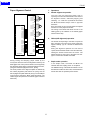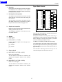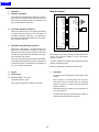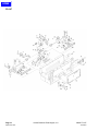
1
HOME
SERVICE MANUAL
Model
FS-107
SECOND EDITION
NOVEMBER 2000
CSM-FS107
KONICA BUSINESS TECHNOLOGIES, INC.
HOME
HOME
FS-107
SERVICE MANUAL
NOVEMBER 2000
SECOND EDITION
HOME
IMPORTANT NOTICE
Because of the possible hazards to an inexperienced
person servicing this equipment, as well as the risk of
damage to the equipment, Konica Business Technologies strongly recommends that all servicing be performed by Konica-trained service technicians only.
Changes may have been made to this equipment to
improve its performance after this service manual was
printed. Accordingly, Konica Business Technologies,
Inc., makes no representations or warranties, either
expressed or implied, that the information contained in
this service manual is complete or accurate. It is understood that the user of this manual must assume all risks
or personal injury and/or damage to the equipment while
servicing the equipment for which this service manual
is intended.
Corporate Publications Department
© 2000, KONICA BUSINESS TECHNOLOGIES, INC.
All rights reserved.
Printed in U.S.A.
HOME
FS-107
CONTENTS
OUTLINE
PRODUCT SPECIFICATIONS ......................................... 1
Type .......................................................................... 1
Functions .................................................................. 1
Stapler kit .................................................................. 2
Machine data ............................................................ 2
Maintenance ............................................................. 2
Machine environment ............................................... 2
CENTRAL CROSS SECTION .......................................... 3
DRIVE SYSTEM DIAGRAM ............................................. 4
Paper conveyance drive ........................................... 4
Stapler unit drive ....................................................... 5
PAPER CONVEYANCE PATH ......................................... 6
Straight mode ............................................................ 6
Offset mode/staple mode .......................................... 7
UNIT EXPLANATION
EXTERNAL SECTION ..................................................... 9
Composition .............................................................. 9
CONVEYANCE SECTION ............................................. 10
Composition ............................................................ 10
Mechanisms ............................................................ 10
Conveyance control ................................................ 11
Tray up/down control .............................................. 13
PAPER EXIT/STAPLER UNIT ....................................... 15
Composition ............................................................ 15
Mechanisms ............................................................ 15
Paper alignment control .......................................... 17
Paper exit control .................................................... 18
Paper stack control ................................................. 19
Stapler control ......................................................... 20
Staple control .......................................................... 21
OTHER KINDS OF CONTROL ...................................... 23
Movement with power on ........................................ 23
Opening and closing motion of the
front door ............................................................... 23
DISASSEMBLY/ASSEMBLY
DISASSEMBLY/ASSEMBLY ........................................... 25
Removing and reinstalling of the finisher .............. 25
Removing and reinstalling of the tray .................... 25
Replacing the paper exit roller/A ............................ 26
Removing and reinstalling of the up/down wire .... 28
Replacing the stapler cartridge .............................. 29
Removing and reinstalling the stapler unit .......... 30
DIAGRAMS
ELECTRICAL PARTS LAYOUT ..................................... 31
CONNECTOR LAYOUT ................................................. 33
TIME CHART (8.5X11, SORT MODE, 2 SHEETS/SET
2 SETS) ........................................................................ 35
TIME CHART (8.5X11, STAPLE MODE 2 SHEETS,
1 POSITION ................................................................. 36
OVERALL WIRING DIAGRAM ....................................... 37
iii
HOME
FS-107
This page left blank intentionally.
iv
HOME
SAFETY PRECAUTIONS
SAFETY PRECAUTIONS
effect may be caused by altering any aspect of the
machine’s design. Such changes have the potential
of degrading product performance and reducing
safety margins.
Installation Environment
Safety considerations usually are directed toward
machine design and the possibility of human error. In
addition, the environment in which a machine is operated must not be overlooked as a potential safety
hazard.
For these reasons, installation of any modification not
specifically authorized by Konica Business Machines
U.S.A., Inc., is strictly prohibited.
Most electrical equipment is safe when installed in a
normal environment. However, if the environment is
different from what most people consider to be normal, it is conceivable that the combination of the
machine and the room air could present a hazardous
combination. This is because heat (such as from
fusing units) and electrical arcs (which can occur
inside switches) have the ability to ignite flammable
substances, including air.
The following list of prohibited actions is not all-inclusive, but demonstrates the intent of this policy.
When installing a machine, check to see if there
is anything nearby which suggests that a potential hazard might exist. For example, a laboratory
might use organic compounds which, when they
evaporate, make the room air volatile. Potentially dangerous conditions might be seen or smelled. The
presence of substances such as cleaners, paint thinners, gasoline, alcohol, solvents, explosives, or similar items should be cause for concern.
If conditions such as these exist, take appropriate
action, such as one of the following suggestions.
•
Determine that the environment is controlled
(such as through the use of an exhaust hood) so
that an offending substance or its fumes cannot
reach the machine.
•
Using an extension cord or any unauthorized
power cord adapter.
•
Installing any fuse whose rating and physical size
differs from that originally installed.
•
Using wire, paper clips, solder, etc., to replace or
eliminate any fuse (including temperature fuses).
•
Removing (except for replacement) any air filter.
•
Defeating the operation of relays by any means
(such as wedging paper between contacts).
•
Causing the machine to operate in a fashion other
than as it was designed.
•
Making any change which might have a chance
of defeating built-in safety features.
•
Using any unspecified replacement parts.
General Safety Guidelines
The specific remedy will vary from site to site, but the
principles remain the same. To avoid the risk of injury
or damage, be alert for changes in the environment
when performing subsequent service on any machine, and take appropriate action.
This copier has been examined in accordance with
the laws pertaining to various product safety regulations prior to leaving the manufacturing facility to
protect the operators and service personnel from
injury. However, as with any operating device, components will break down through the wear-and-tear of
everyday use, as will additional safety discrepancies
be discovered. For this reason, it is important that the
technician periodically performs safety checks on the
copier to maintain optimum reliability and safety.
Unauthorized Modifications
The following checks, not all-inclusive, should be
made during each service call:
•
Remove the offending substance.
•
Install the machine in a different location.
CAUTION: Avoid injury. Ensure that the copier is
disconnected from its power source before continuing.
Konica copiers have gained a reputation for being
reliable products. This has been attained by a combination of outstanding design and a knowledgeable
service force.
The design of the copier is extremely important. It is
the design process that determines tolerances and
safety margins for mechanical, electrical, and electronic aspects. It is not reasonable to expect individuals not involved in product engineering to know what
v
•
Look for sharp edges, burrs, and damage on all
external covers and copier frame.
•
Inspect all cover hinges for wear (loose or broken).
•
Inspect cables for wear, frays, or pinched areas.
HOME
SAFETY PRECAUTIONS
•
Ensure that the power cord insulation is not damaged (no exposed electrical conductors).
•
Ensure that the power cord is properly mounted
to the frame by cord clamps.
•
Check the continuity from the round lug (GND) of
the power cord to the frame of the copier -- ensure
continuity. An improperly grounded machine can
cause an electrically-charged machine frame.
Applying Isopropyl Alcohol
Care should be exercised when using isopropyl alcohol, due to its flammability. When using alcohol to
clean parts, observe the following precautions:
Safeguards During Service Calls
Confirm that all screws, parts, and wiring which are
removed during maintenance are installed in their
original positions.
•
When disconnecting connectors, do not pull the
wiring, particularly on AC line wiring and high
voltage parts.
•
Do not route the power cord where it is likely to
be stepped on or crushed.
•
Carefully remove all toner and dirt adhering to any
electrical units or electrodes.
•
After part replacement or repair work, route the
wiring in such a way that it does not contact any
burrs or sharp edges.
•
Do not make any adjustments outside of the
specified range.
•
Remove power from the equipment.
•
Use alcohol in small quantities to avoid spillage
or puddling. Any spillage should be cleaned up
with rags and disposed of properly.
•
Be sure that there is adequate ventilation.
•
Allow a surface which has been in contact with
alcohol to dry for a few minutes to ensure that the
alcohol has evaporated completely before applying power or installing covers.
Summary
It is the responsibility of every technician to use professional skills when servicing Konica products. There
are no short cuts to high-quality service. Each copier
must be thoroughly inspected with respect to safety
considerations as part of every routine service call.
The operability of the copier, and more importantly,
the safety of those who operate or service the copier,
are directly dependent upon the conscientious effort
of each and every technician.
Remember...when performing service calls, use good
judgement (have a watchful eye) to identify safety
hazards or potential safety hazards that may be present, and correct these problem areas as they are
identified -- the safety of those who operate the copier
as well as those who service the copier depend on it!
vi
HOME
FS-107
FS-107 PRODUCT SPECIFICATIONS
Type
Type:
Built-in type compact finisher
(multiple trays type)
Option:
Finisher tray (FT-107) (Up to
2 trays can be installed)
Note 2:
The number of stacked sheets in staple
mode must not exceed the stack sheet
capacity for non-staple mode.
Note 3:
Small size:
8.5x5.5R
Medium size:
Everything other than
small size, large size,
special media.
8.5x14, 11x17
Functions
Type of paper:
Same as the main body
Large size:
Modes:
Straight mode
Special paper: Thin paper (16 lb. or
less), thick paper (over 34
lb.), blueprint masters,
OHP, etc.
Offset mode (shift)
Staple mode
Paper size
Straight paper exit:
11 x 17, 8.5 x 14R, 8. 5 x 11,
8.5 x 11R, 8.5 x 5.5, 8.5 x 5.5R
Note 4:
The stacking capacity of the option
conforms to the stacking capacity of tray 1.
Offset:
11 x 17, 8.5 x 14, 8.5 x 11, 8.5
x 11R, 8.5 x 5.5R
Paper curling:
1 position staple:
11 x 17, 8.5 x 14, 8.5 x 11, 8.5
x 11R, 8.5 x 5.5R
2 position staple:
11 x 17, 8.5 x 14, 8.5 x 11, 8.5
x 5.5R
Maximum 10mm
Five copy sheets
Curl
Maximum
Paper capacity:
2 trays: 100 +1000 = 1,100
sheets
Amount of sort
off-setting:
3 trays: 100 + 100 + 600 =
800 sheets
20mm (8.5 x 5.5R)
4 trays: 100 x 4 = 400 sheets
Copy
Paper weight:
13 lb. to 53 lb. papers
Stack capacity:
(21 lb. high-quality paper)
With 2 standard trays
Small Medium Large Special
size
size
size
media
100
100
100
10
Nonstaple sheets sheets sheets sheets
Tray 1
10
10
10
Staple sets
sets
sets
Non1000
300
50
staple
sheets sheets sheets
Tray 2
50
20
Staple
sets
sets
Note 1:
30mm
The above figures apply only to if stacked
paper is all of the same size.
1
HOME
FS-107
Machine data
Stapler kit
Staple ability
Power source:
Maximum 50 sheets (with 21
lb. paper, paper thickness
less than 5mm)
DC24V/5V (supplied from the
main body)
Stapler capacity:
5,000 staples/cartridge
Maximum power
Consumption:
Staple position:
A = 8.6mm ± 3mm
Weight:
28.6 lb.
B = 8.6mm ± 3mm
External
dimensions:
Length 30.8 in.
C = refer to following table
Maximum 70VA
D = 10.5mm ± 3mm
Depth 19.8 in.
E = 8.0mm ± 3mm
Height 15.4 in.
Paper Size
C (mm)
A3/A4
60±4
B4/B5
53±4
A4R/A5
90±4
B5R
80±4
A5R
63±4
F4 (8 x 13)
90±4
Temperature:
50 to 86 F
F4 (8.125 x 13)
91.5±4
Humidity:
10 to 80%RH
F4 (8.25 x 13)
93±4
F4 (8.5 x 13)
95±4
11 x 17/8.5 x 11
52±4
8.5 x 14/8.5 x 11R
95±4
5.5 x 8.5
95±4
5.5 x 8.5R
60±4
Maintenance
Maintenance:
Same as the main unit
Machine environment
(below condensation-forming
conditions)
Caution: The contents of this service manual may be
changed without notice.
2
HOME
FS-107
CENTER CROSS SECTION
Tray 1
Exit roller/A
Conveyance roller
Conveyance rollers
Stapler unit
Tray 2
Conveyance belt
3
HOME
FS-107
DRIVE SYSTEM DIAGRAM
Paper Conveyance Drive
Paper conveyance
motor (M701)
Conveyance roller
Paper exit motor (M702)
Conveyance roller
Exit roller A
Paper jam release knob
Conveyance belt
Conveyance roller
Tray up/down wires
Trays
Tray up/down motor (M706)
4
HOME
FS-107
Stapler Unit Drive
Stapler unit
Alignment plates
Stapler shift
motor (M705)
Alignment motor
(rear) (M703)
Alignment motor
(front) (M704)
5
HOME
FS-107
PAPER CONVEYANCE PATH
In the finisher, two different paper conveyance paths are
used, changing by the mode selected.
Straight Mode
In this mode, paper conveyed to the finisher is exited
straight into the tray. (For small size paper, the
operation of OffsetMode/Stapling Mode takes place,
even in the straight paper exit mode.)
6
HOME
FS-107
Offset Mode/Staple Mode
In the offset mode or staple mode, paper conveyed
to the finisher is stacked once by the reverse
rotation of the exit roller. In the offset mode, this
stacked paper is offset by the paper alignment
plates. In the staple mode, the paper is stapled. When
the respective process is finished, the paper is exited
to the tray by the exit roller.
Paper exit roller
Alignment plate
7
HOME
FS-107
This page left blank intentionally.
8
HOME
FS-107
EXTERNAL SECTION
Composition
Paper conveyance cover
Tray 1
Optional tray 1
(FT-107)
Optional tray 2
(FT-107)
Conveyance plate
Front door
Tray 2
Stapler unit
9
HOME
FS-107
CONVEYANCE SECTION
Composition
Tray 1
Paper conveyance motor (M701)
Tray up/down wire
Conveyance rollers
Tray 2
Conveyance roller
Tray up/down motor (M706)
Mechanisms
Mechanism
System
Paper Conveyance
Conveyance rollers
Tray Up/Down *1
Wire drive
Tray Up/Down Accident
Prevention *2
Shutter
Tray up/down wires
*1 Tray up/down
The paper exit gate position is fixed; switching
between trays is accomplished by changing the
tray position up/down mechanism.
Trays
Tray up and down is done by the tray up/down
motor (M706), which the tray up/down wires to
drive the tray up or down.
Tray up/down
motor (M706)
10
HOME
FS-107
Conveyance Control
*2 Prevention of tray up/down accident
To prevent the accident insertion of the hand into
the paper exit gate during tray motion up or down,
the paper exit gate is equipped with a shutter. The
shutter is driven by the reverse motion of the
paper pressure motor (M707), closing the paper
exit gate when the tray is in motion.
Shutter
5VDC
PS3
SGND
24VDC
24VDC
24VDC
5VDC
5VDC
SGND
SGND
PGND
PGND
PGND
Paper pressure motor (M707)
PS3
24VDC
24VDC
M701 OUT A
M701 OUT A
M701 OUT B
M701 OUT B
SGND
SGND
M ACK
SGND
S REQ
M RXD
SGND
S ACK
M REQ
SGND
M TXD
MAIN BODY
M701
5VDC
PS702
SGND
PS702
5VDC
PS717
SGND
PS717
24VDC
MS701
MS701
FS CB
Conveyance is accomplished by the drive force of the
M701 (paper conveyance motor), which is transmitted to
the conveyance rollers. The M701 is linked with the main
body, so that rotation is set to low or high speed according
to the conveyance movement during copying.
The M701 is controlled by the FS CB (FS control board).
Related signals are provided by the PS702 (paper
entrance detect PS), PS717 (conveyance cover open/
close detect PS) and the MS701 (front door switch) and
PS3 (paper exit PS) of the main body.
1.
Operation
As paper passes by the PS3 of the main body, the
M701 conveys the paper at a low speed in relation
with the paper exit velocity of the main body. When
the end of the paper passes through the PS3, the
M701 then conveys the paper at high speed. The
M701 again changes to low speed after the specified
period of time when the end of the paper passes
through the PS702, ready to convey the next sheet of
paper.
11
HOME
FS-107
2.
Signals
b.
a.
Input signals
(1) M701 OUTA, M701 OUTA, M701 OUTB, M701
OUT B (FS CB -> M701)
(1) PS3 (PS3 -> PRDB)
Output signals
M701 drive control signal
When the main body paper exit section detection
signal detects paper, [H] is output.
(2) PS702 (PS702 -> FS CB)
24V
Conveyance section paper entrance detection signal
0V
[L]: No paper is present
[H]: Paper is present
(2) M ACK (FS CB -> MAIN BODY)
(3) PS717 (PS717 -> FS CB)
Transmission of OK signal from the finisher to the
main body.
Conveyance plate opening/closing detection signal
[L]: Conveyance plate open
(3) S REQ (FS CB -> MAIN BODY)
[H]: Conveyance plate closed
Transmission of request signal from the finisher to
the main body.
(4) MS701 (MS701 -> FS CB)
(4) M RXD (FS CB -> MAIN BODY)
Power supply line for each load
Serial data sign sending the movement condition of
the finisher to the main body CB.
When the finisher front door is closed, 24VDC is
supplied to each load.
(5) S ACK (MAIN BODY -> FS CB)
Transmission of OK signal from the main body to the
finisher.
(6) M TXD (MAIN BODY -> FS CB)
Serial data sign sending the movement condition of
the main body to the finisher.
(7) M REQ (MAIN BODY -> FS CB)
Transmission of request signal from the main body to
the finisher.
12
HOME
FS-107
Tray Up/Down Control
24VDC
24VDC
24VDC
5VDC
5VDC
SGND
SGND
PGND
PGND
PGND
M706 DRIVE 1
M706 DRIVE 2
MAIN BODY
Operations
a.
Tray lower limit detection operation
With the sub power swich turnd ON, and the PS706
OFF, the M706 is reversed and the tray is lowered
until the PS706 is turned ON.
M706
5VDC
PS706
SGND
SGND
SGND
M ACK
SGND
S REQ
M RXD
SGND
S ACK
M REQ
SGND
M TXD
1.
b.
PS706
5VDC
PS703
SGND
PS703
5VDC
PS716
SGND
PS716
Tray count operation
One, two, or no optional trays can be installed.
If PS716 goes OFF after the low limit of the tray has
been detected, the machine judges that no optional
trays are installed.
When PS716 is ON, optional tray 1 is in place; in this
condition the M706 rotates normally, raising the tray
one step up until PS716’s detection position where
motion is stopped. Whether PS716 is ON or OFF at
this point determines whether optional tray 2 is in
place or not.
The number of trays is counted by means of a series
of operations.
After the tray count, the default tray that was set in the
key operator mode is set in the exit position.
24VDC
MS702
MS702
FS CB
The paper exit position of the FS is fixed, the selected tray
is elevated or lowered to the paper exit position. Control of
the tray up/down is by the M706 (tray up/down motor)
which drives wires which is connected to and moves the
trays up and down.
The M706 is controlled by the FS CB (FS control board).
Related signals are provided by the PS703 (paper exit
detect PS), PS706 (tray lower limit detect PS), PS716
(tray count PS) and the MS702 (shutter switch).
c.
Tray movement operation
If the exit tray has been selected at the LCD, then
when copying starts M706 turns ON and moves the
selected tray so that it sets into the exit position.
The number of times PS703 switches ON and OFF
sets the selected tray into the paper exit position.
d.
Shutter switch operation
While the tray is in motion, the shutter, which
prevents the fingers or foreign objects from entering
the paper exit gate, is closed, with MS702 in the ON
position supplying 24VDC to the various loads.
While the tray is being raised or lowered the shutter
is opened and MS702 is OFF, interrupting the flow of
electricity and halting the motion of the FS.
13
HOME
FS-107
2.
Signals
a.
Input signals
(1) PS706 (PS706 -> FS CB)
Tray lower limit detection signal
[L]: Not at lower limit
[H]:Lower limit
(2) PS703 (PS703 -> FS CB)
Paper exit detection signal
[L]: Top face
[H]:Not at top face
(3) PS716 (PS716 -> FS CB)
Tray installation detection signal
[L]: No tray
[H]:Tray in position
(4) PS702 (PS702 -> FS CB)
The power supply line for each load.
24VDC is supplied to each load when the shutter is
closed.
b.
Output signal
(1) M706 DRIVE 1, 2 (FS CD -> M706)
M706 drive control signal
The drive direction of the M706 is controlled by two
signals which change the direction of the electrical
current.
14
HOME
FS-107
PAPER EXIT/STAPLER UNIT
Composition
Exit roller/A
Alignment plates
Trays
Stapler unit
Alignment motors
(M703, M704)
Stapler shift motor (M705)
Mechanisms
Alignment plate (rear)
Mechanism
System
Paper Alignment *1
Separate plates for front
and rear
Paper Exit *2
Exit roller/A
Paper Stacking *3
Exit roller/A
Conveyance belt
Stapler Unit Shift *4
Stapler shift motor
Alignment plate (front)
Alignment motor (rear)
(M703)
*1 Paper alignment
Paper conveyed to the paper exit gate by the conveyance roller is stacked by reverse rotation of the
paper exit roller/A. The stacked paper is aligned
by the alignment plates. Independently-driven
alignment plates are set on both the front and rear
sides, allowing independent operation at the front
and rear during shift mode. The alignment plates
are driven by alignment motors M704 (front) and
M703 (rear).
Alignment motor (front)
(M704)
15
HOME
FS-107
*3 Paper stack
*2 Paper exit
In the offset mode or staple mode, paper conveyed to the paper exit gate by the conveyance
rollers is then conveyed to the stack position by
paper exit roller/A running in reverse direction.
The conveyed paper is sent to the stopper by the
friction of the conveyance belt and stacked.
In the straight mode, paper conveyed to the paper
exit gate by the conveyance rollers is conveyed to
the tray through paper pressure being applied to
paper exit roller/A by the paper pressure motor
(M707) and the roller being made to run forward.
(Does not apply to small paper sizes.)
In offset mode or staple mode, when the stacked
paper is conveyed, paper pressure being applied
to paper exit roller/A by the paper pressure motor
(M707) and the roller being made to run forward,
all the stacked paper is conveyed into the tray.
Straight mode
Paper exit rollerA
*4 Stapler unit shift
The stapler unit is driven by the stapler shift
motor; the stapler unit is fixed on the staple base
and moved by a belt along a rail. Owing to the
shape of the rail, when the stapler unit is moved to
either the forward or rear positions, the unit
rotates and it is possible to staple slantwise.
When the stapler is set to staple in two locations,
it moves to the first location, puts in the first
staple, then moves to the second location to put
in the second staple.
Offset mode/staple mode
Stapler unit
Rails
Stapler shift motor
(M705)
Belt
16
HOME
FS-107
Paper Alignment Control
24VDC
24VDC
24VDC
5VDC
5VDC
SGND
SGND
PGND
PGND
PGND
24VDC
24VDC
M702 OUT A
M702 OUT A
M702 OUT B
M702 OUT B
M702
24VDC
24VDC
M703 OUT A
M703 OUT A
M703 OUT B
M703 OUT B
M703
24VDC
24VDC
M704 OUT A
M704 OUT A
M704 OUT B
M704 OUT B
M704
SGND
SGND
M ACK
SGND
S REQ
M RXD
SGND
S ACK
M REQ
SGND
M TXD
MAIN BODY
5VDC
PS702
SGND
PS702
5VDC
PS709
SGND
PS709
5VDC
PS710
SGND
PS710
1.
Operations
a.
Normal alignment operation
The front and rear alignment plates work in
symmetry to the front and rear based on the center of
the alignment section, alternately aligning and
releasing. To create this symmetrical movement
the M703 and M704 always rotate in opposite
directions.
Every five sheets of the conveyed paper are aligned
and sent on to the paper exit section.
The timing of the M703 and M704 are set to the
starting point by the ON/OFF of the PS702 (paper
entrance detect PS).
b.
Offset (shift alignment) operation
The sheets corresponding to odd sets of copies are
fed to the paper exit unit as soon as they have been
aligned normally. (Up to 5 sheets are stacked and
exited.)
During the alignment operation for even sets of
copies, M703 and M704 rotate in the same direction,
shifting the sheets forward from the center. The
aligned sheets are then sent to the paper exit unit.
(Up to 5 sheets are stacked and exited.
FS CB
During sorting and stapling, paper exited by the
conveyance section is sent to the alignment section by the
M702 (paper exit motor) reverse direction, then aligned by
the alignment plates driven by the M703 (alignment motor,
(rear)) and the M704 (alignment motor, (front)).
The home position of the alignment plates is detected by
the PS709 (alignment plate detect PS (rear)) and the
PS710 (alignment plate detect PS (front)). The FS CB (FS
control board) controls the M702, M703 and M704. The
related signal are passed to the PS702 (paper entrance
detect PS).
c.
Staple mode operation
In the staple mode, the M703 and M704 are
released after the stapling action is completed.
The ON/OFF timing of the M703 and M704 is set as
the M702 is turned from OFF to ON, and the PS702 is
turned OFF after the specified period of time.
17
HOME
FS-107
2.
Signals
a.
Input signals
Paper Exit Control
(1) PS709 (PS709 -> FS CB)
5VDC
PS3
SGND
Detection signal of the home position of the
alignment plate (rear)
[L]: Non-home position
24VDC
24VDC
24VDC
5VDC
5VDC
SGND
SGND
PGND
PGND
PGND
[H]: Home position
(2) PS710 (PS710 -> FS CB)
Detection signal of the home position of the
alignment plate (front)
[L]: Non-home position
24VDC
24VDC
M702 OUT A
M702 OUT A
M702 OUT B
M702 OUT B
M702
M707 DRIVE 1
M707 DRIVE 2
M707
M708 DRIVE 1
M708 DRIVE 2
M708
SGND
SGND
M ACK
SGND
S REQ
M RXD
SGND
S ACK
M REQ
SGND
M TXD
[H]: Home position
b.
PS3
Output signals
–
(1) M702 OUT A, M702 OUT A, M702 OUT B,
–
M702 OUT B (FS CB -> M702)
MAIN BODY
Drive control signal for M702
5VDC
PS701
SGND
PS701
5VDC
PS702
SGND
PS702
5VDC
PS703
SGND
PS703
5VDC
PS707
SGND
PS707
FS CB
24V
Papers that have already been aligned or stapled are
exited by the paper exit roller.
0V
A mechanical clutch is connected to M702 (paper exit
motor). A mechanical clutch can convey the forward
direction driving power to the exit roller with certain
movement.
–
(2) M703 OUT A, M703 OUT A, M703 OUT B,
–
M703 OUT B (FS CB -> M703)
Drive control signal for M703
The M702 is responsible for speed control for connection
with the mechanical clutch, for sending the alignment
section at the reversal rotation, and also during the usual
paper exit.
24V
0V
The M702 is controlled by the FS CB (FS control board).
The related signals are M707 (paper pressure motor),
M708 (stapler motor), PS701 (paper pressure PS), PS702
(paper entrance detect PS), PS703 (paper exit detect PS),
and PS707 (no paper detect PS).
–
(3) M704 OUT A, M704 OUT A, M704 OUT B,
–
M704 OUT B (FS CB -> M704)
Drive control signal for M704
24V
0V
18
HOME
FS-107
1.
Paper Stack Control
Operation
During paper exit, both upper and lower exit rollers
are compressed as a consequence of the operation
performed by M707, and that condition is detected by
the ON/OFF state of PS701.
a.
24VDC
24VDC
24VDC
5VDC
5VDC
SGND
SGND
PGND
PGND
PGND
Non-staple mode operation
The ON/OFF timing of M702 is such that it turns ON
during the OFF of PS3, and turns OFF during the
OFF of PS702.
SGND
SGND
M ACK
SGND
S REQ
M RXD
SGND
S ACK
M REQ
SGND
M TXD
After the paper exit tray goes up until PS703 turns
ON, M706 moves the tray up and down in order to
keep the ON state of PS703 during paper exit.
b.
Staple mode operation
M702 turns ON a certain time after M708 finishes the
stapling operation and turns OFF.
MAIN BODY
The subsequent operations are the same as for the
non-staple operation.
2.
Signals
a.
Input signal
M706
5VDC
PS702
SGND
PS702
5VDC
PS703
SGND
PS703
5VDC
PS704
SGND
PS704
5VDC
PS706
SGND
PS706
5VDC
PS716
SGND
PS716
FS CB
When the stack of the papers on the paper exit tray is full,
a message is put up on the LCD.
During the automatic switching mode of the tray, a
message is not put up on the LCD. The tray located 1 step
below is brought to the paper exit position by a vertical
movement of M706 (tray up/down motor).
(1) PS701 (PS701 -> FS CB)
The M706 is controlled by FS CB (FS control board).
Pressure detection signal of the exit paper compressing plate
The related signals are PS702 (paper entrance detect
PS), PS703 (paper exit detect PS), PS704 (tray full-stack
detect PS), PS706 (tray lower limit detect PS), and PS716
(tray count PS).
[L]: Pressure
[H]: Release
b.
M706 DRIVE 1
M706 DRIVE 2
The automatic switching mode of the tray can be
controlled using the 25 modes of the main unit.
Output signals
(1) M707 DRIVE 1,2 (FS CB -> M707)
M707 drive control signal
The drive direction of the M707 is controlled by two
signals which change the direction of the electrical
current.
(2) M708 DRIVE 1,2 (FS CB -> M708)
M708 drive control signal
The drive direction of the M708 is controlled by two
signals which change the direction of the electrical
current.
19
HOME
FS-107
1.
Operation
a.
Up/down operation
Stapler Control
When the tip of the paper turns PS702 ON, the tray is
driven down by a certain amount. After the rear of the
paper turns PS702 OFF, M706 turns ON driving the
tray up until PS703 is turned ON.
b.
24VDC
24VDC
24VDC
5VDC
5VDC
SGND
SGND
PGND
PGND
PGND
Full-stack detection operation
When a tray other than tray 1 is selected and PS703
is turned ON when PS704 is ON, the paper-full
condition is detected. When tray 1 is selected and
PS 703 is turned ON when PS706 is ON, the paperfull condition is detected.
c.
MAIN BODY
When tray 1, optional tray 1, and optional tray 2 are
selected and the paper-full condition is detected,
M706 drives the tray up so that PS703 is turned OFF
and then ON again, and the immediately lower tray is
set at the paper exit position.
a.
Input signal
PS708
FS CB
M705 (staple shift motor) performs staple displacement
control by moving the stapler unit up to the stapler
operation position.
When tray 2 is selected and the paper-full condition
is detected, M706 drives the tray down until PS716 is
turned ON, and then up until PS703 is turned ON, set
tray 1 at the paper exit position.
Signal
5VDC
PS708
SGND
M705
SGND
SGND
M ACK
SGND
S REQ
M RXD
SGND
S ACK
M REQ
SGND
M TXD
Automatic tray switching operation
2.
24VDC
24VDC
M705 OUT A
M705 OUT A
M705 OUT B
M705 OUT B
The home position of the stapler unit is detected by PS708
(stapler unit HP detect PS).
M705 is controlled by FS CB (FS control board).
1.
Operation
The stapler unit is usually at the home position of the
finisher.
(1) PS704 (PS704 -> FS CB)
When receiving a command signal from the main
unit, M705 moves the stapler unit to the stapling
position according to paper size and starts the
stapling operation.
Paper-full detection signal
Goes [H] when paper-full condition is detected.
After finishing the copy, M705 moves the stapler unit
to its home position.
The M705 OFF timing is controlled by the number of
driving steps after PS708 is turned OFF.
20
HOME
FS-107
2.
Signal
a.
Input signal
Staple Control
(1) PS708 (PS708 -> FS CB)
Detection signal of the home position of the stapler
unit
24VDC
24VDC
24VDC
5VDC
5VDC
SGND
SGND
PGND
PGND
PGND
[L]: Non-home position
[H]: Home Position
b.
Output signal
–
(1) M705 OUT A, M705 OUT A, M705 OUT B,
–
M705 OUT B (FS CB -> M705)
24VDC
24VDC
M705 OUT A
M705 OUT A
M705 OUT B
M705 OUT B
M705
M707 DRIVE 1
M707 DRIVE 2
M707
M708 DRIVE 1
M708 DRIVE 2
M708
SGND
SGND
M ACK
SGND
S REQ
M RXD
SGND
S ACK
M REQ
SGND
M TXD
Drive control signal for M705
24V
MAIN BODY
5VDC
PS701
SGND
PS701
5VDC
PS708
SGND
PS708
5VDC
PS712
SGND
PS712
5VDC
PS713
SGND
PS713
FS CB
0V
In staple mode, stapling is performed using the driving
force of the M708 (stapler motor).
M708 is controlled by FS CB (FS control board).
The related signals are M705 (stapler shift motor), M707
(paper pressure motor), PS701 (paper pressure PS),
PS708 (stapler unit HP detect PS), PS712 (stapler HP
detect PS), PS713 (no-staple PS), and PS714 (stapler
ready PS).
The maximum number of sheets that can be stapled, and
the operation when stapling is not possible, can be
chosen in the 25 mode of the main body.
21
HOME
FS-107
1.
Operation
2.
Signals
a.
Stapler operation
a.
Input signals
After the aligning operation of the last paper, M707 is
turned ON and compresses the paper using the exit
rollers. Then, M708 is turned ON and stapling
begins.
(1) PS712 (PS712 -> FS CB)
When PS701 is turned OFF, M707 is turned OFF,
PS712 is turned ON, and M708 is turned OFF.
[H]: Non-home position
M708 home position detection signal
[L]: Home position
(2) PS713 (PS713 -> FS CB)
For continuous stapling, M705 is not turned ON, and
the stapler unit waits for the next stapling at the same
position.
No-staple detection signal of the stapler unit
[L]: With staple
[H]: No staple
In the case of 2 stapling positions, the first staple is
executed and then M705 moves the stapler to the
specified position for the second staple. M708 then
turns ON and executes the second staple. At this
moment, if continuous stapling has been selected,
the stapler unit stops at the immediately previous
stapling position. When the first stapling operation of
the next paper is done, M705 moves the stapler unit
for the second stapling operation.
(3) PS714 (PS714 -> FS CB)
Detects whether staple is in position for stapling by
stapler unit (whether staple is present at point just
ahead of where it is actually driven from the stapler).
[L]: With staple
[H]: No staple
After the copy is finished, the stapler unit returns to
its home position.
b.
No-staple detection control
The PS713 is equipped to detect the no-staple
condition of the stapler unit. When the staple is not
present, the LCD (display board) of the main unit
shows a message indicating the no-staple condition.
c.
Stapler Initial Operation
After replacing the stapler cartridge, M708 is driven
until staples are detected in the PS714, performing
up to a maximum of 16 blank stapling operations,
then the staples are positioned just in front of the
stapling position.
22
HOME
FS-107
OTHER CONTROLS
Movement With Power On
When the power is turned ON, the finisher performs
the following initialization operations.
1. M707 turns ON and the paper exit gate pressure
is released.
2. PS708 (stapler unit HP detect PS) detects
whether the stapler unit is on stand-by in home
position.
3. M703 (alignment motor (rear)) and M704 (alignment motor (front)) turn ON and perform a home
position search for the alignment plates (front and
rear).
4. The paper exit gate shutter closes and the tray
count operation takes place.
Opening and Closing Motion of the Front
Door
1. In case PS707 is ON, it makes M702 go through a
normal rotation and performs a paper exit operation.
2. M707 turns ON and the paper exit gate pressure is
released.
3. PS708 (stapler unit HP detect PS) detects
whether the stapler unit is on stand-by in home
position.
4. M703 (alignment motor (rear)) and M704 (alignment motor (front)) turn on and perform a home
position search for the alignment plates (front and
rear).
23
HOME
FS-107
This page left blank intententionally.
24
HOME
FS-107
DISASSEMBLY AND ASSEMBLY
Caution: Make sure the power plug is
uplugged.
(2) Take out each 2 sets of set screws from the wire
fittings on front and rear.
Removal and Reinstalling of the Finisher
(1) Open the front door, then insert a pen, or the like,
into the hole at the bottom of the finisher
Set
screws
Set
screws
Caution: There is a risk of the internal lever
becoming deformed, so do not push it in
hard.
Wire fittings
(3) Pull out the tray downward from the frame that it is
installed.
Caution 1: Taking out the set screws from the fixed
fittings will make the tray frame fall out.
Caution 2: Take care not to drop the rollers installed
on the tray.
(2) Pull the finisher forward and remove it.
Removal and Reinstalling of the Tray
(1) Take out each 3 sets of set screws and remove
the cover’s front and rear.
Set screws
Set screws
Cover
(rear)
Cover
(front)
Set screws
25
HOME
FS-107
Replacing the Paper Exit Roller/A
(4) Install by reversing the removal procedure.
Caution: In case of fixing the tray frame to the fixed
fittings, make sure that the set screws are
fastened so that the tray is horizontal.
(Use the 6 marks at each of the front and
rear as guides for horizontal adjustment.)
(1) Remove the finisher from the main body.
(2) Take off 5 lids and 6 set screws and remove the
paper conveyance cover.
Lid
Set screws
Paper conveyance cover
(3) Take out each of the single springs and set screws
and remove the plate spring roller.
Set screws
Plate spring rollers
Spring adjustment
plate
Caution: Do not remove the screws for the spring
adjustment plate.
26
HOME
FS-107
(8) Remove the 5 E-rings and pull out the shaft from
the paper exit roller/A.
(4) Remove the E-ring and remove the cam shaft.
Caution: Be careful to not drop the pin inside the
paper exit roller/A.
Shaft
E-ring
Shaft
E-rings
Paper exit
roller/A
Pin
E-rings
Pin
(5) Take out the 2 sets of set screws and remove the
set of 2 plate springs.
Set screws
(9) Replace the paper exit roller/A.
Plate spring
(10) Install by reversing the removal procedure.
(6) Take out 1 set screw and remove the plate.
(7) Remove the E-ring that affixes the belt gear, slide
the gear and remove the belt.
Caution: Be careful to not drop the pin inside the
gear.
Set screw
Plate
E-ring
Belt
Pin
27
HOME
FS-107
Removing/Reinstalling the Up/Down Wire
(1) Take out the 3 sets of set screws and remove the
front cover and rear cover.
(2) Remove the 2 set screws from each of the front
and rear wires and then remove the tray unit.
Caution: Perform the removal/installating of the
front up/down wire before performing the
removal/installating of the rear up/down
wire.
(3) Loosen the 2 set screws and release the pulley
tension plate in front from its fixed position.
(4) Remove the E-ring of the lower pulley (in front).
(5) Remove the lower pulley (in front) and remove the
up/down wire in front.
Caution: Ensure that the pulley installation gear is
horizontal with respect to the casing.
(7) Wind the up/down wire once around the lower
pulley front) counter-clockwise, and string it to the
upper pulley (front).
(8) Down the up/down wire strung to the upper pulley
(front) to the lower pulley and wind it around 4
times counter-clockwise, and attach the metallic
ball on the end to the side of the lower pulley
(front).
(9) Attach the E-ring and affix the lower pulley (front).
(10) Fasten the 2 set screws while pulling up the pulley
tension plate (front), applying 3kg tension.
Caution: Apply the required amount of tension at
the time of affixing the pulley tension plate
by using such devises as a tension gauge.
(6) Attach the metallic ball of the up/down wire on the
inner surface of the lower pulley (in front), and
insert into the shaft. The metallic ball to be set is
the one longer from the wire fitting.
Required value: 3kg
Also, check to see if the gear position at which the
pulley is installed is in line with the opposite side.
Set screws
28
Pulley tension
plate
HOME
FS-107
Replacing the Stapler Cartridge
(11) Refer to procedures 3 to 6 and remove the up/
down wire on the rear.
(1) Operate the stapler cartridge replacing from the
operation panel. The stapler unit will move and
position itself to the front.
(2) Turn the stapler cartridge replace knob on the
stapler unit.
Stapler unit
(12) Wind the up/down wire once around the lower
pulley (rear) in the clockwise, and string it to the
upper pulley (rear).
(13) Down the up/down wire strung to the upper pulley
(rear) to the lower pulley and wind it around 4
times clockwise, and attach the metallic ball on the
end to the side of the lower pulley (rear).
Cartridge replace knob
(3) Remove the old cartridge and push a new
cartridge firmly in place.
(14) Attach the E-ring and affix the lower pulley (rear).
(15) Fasten the 2 set screws while pulling up the pulley
tension plate (rear), applying 3kg tension.
Stapler
cartridge
29
HOME
FS-107
Removing/Reinstalling the Stapler Unit
(5) Take out the set screw from the unit saddle, slide
out and remove the stapler unit.
(1) Remove the finisher from the main unit.
(2) Take out the fixing plates of the plate affixing the
stapler unit, from the rear of the finisher unit.
(3) Slide the plate and remove.
Stapler units
Plate
Set screw
Set screw
(6) Install by reversing the removal procedure.
Caution: When reinstalling the plate, be sure to insert the plate into the insides of the hooks.
(4) Take out the connector and 1 grounding screw
from the stapler unit.
Ground screw Ground
Connector
30
HOME
FS-107
FS-107 ELECTRICAL PARTS LAYOUT DRAWING
PS711 Tray upper limit detect PS
PS704 Tray full-stack detect PS
PS703 Paper exit detect PS
PS716 Tray count PS
PS706 Tray lower limit detect PS
M706 Tray up/down motor
PS707 No paper detect PS
PS709 Alignment plate
detect PS (rear)
M703 Alignment motor (rear)
PS710 Alignment plate
detect PS (front)
M704 Alignment motor (front)
M706 Tray up/down motor
PS708 Stapler unit HP
detect PS
M705 Stapler shift motor
MS701 Front door switch
31
FS CB FS control board
HOME
FS-107
M709 Cooling fan motor
PS702 Paper entrance detect PS
M702 Peper exit motor
M701 Paper conveyance motor
PS701 Paper pressure PS
PS705 Shutter PS
MS702 Shutter switch
M707 Paper pressure motor
PS717 Conveyance cover open/close detect PS
PS714 Stapler ready detect PS
PS712 Stapler HP detect PS
PS713 No-staple PS
M708 Stapler motor
32
HOME
FS-107
FS-107 CONNECTOR LAYOUT DRAWING
CN736 (W:3pin)
CN735 (W:3pin)
CN734 (W:3pin)
CN744 (W:3pin)
CN737 (W:3pin)
CN756 (W:15pin)
CN738 (W:3pin)
CN741 (W:3pin)
CN740 (W:3pin)
CN724 (W:6pin)
CN756 (W:15pin)
CN723 (W:6pin)
CN725 (W:6pin)
CN756 (W:15pin)
CN739 (W:3pin)
CN726 (BK:2pin)
CN751 (W:1pin)
33
HOME
FS-107
CN753 (W:1pin)
CN752 (W:3pin)
CN701 (10pin)
CN715 (30pin)
CN706 (2pin)
CN709 (12pin)
CN712 (2pin)
CN711 (2pin)
CN704 (12pin)
CN714 (15pin)
CN702 (11pin)
FS CB
CN708 (8pin)
CN300 (BK:24pin)
CN713 (3pin)
CN10 (2pin)
CN703 (12pin)
CN705 (W:6pin)
CN707 (30pin)
CN731 (W:3pin)
CN722 (W:6pin)
CN721 (W:6pin)
CN733 (W:3pin)
CN732 (W:3pin)
CN734 (W:3pin)
CN730 (BK:2pin)
CN745 (W:3pin)
34
Paper
conveyance
motor
Paper exit
motor
Alignment
motor
Stapler shift
motor
Paper
pressure
motor
Tray up/down
motor
M701
M702
35
M703,704
M705
M707
M706
Lower
Raise
Open
Pressure
R
F
Shift
Alignment
Reverse
Stop
140mm/s
600mm/s
140mm/s
600mm/s
No paper detect PS
PS707
Time (sec)
Paper entrance detect PS
Exit PS
Item
PS702
PS3
Symbol
0
1
2
3
4
5
6
7
8
9
10
HOME
FS-107
TIME CHART (8.5X11, SORT MODE, 2 SHEETS/SET, 2 SETS)
Paper exit
motor
M702
36
Stapler shift
motor
Stapler motor
Paper
pressure
motor
Tray up/down
motor
M705
M708
M707
M706
M703,704 Alignment
motor
Paper
conveyance
motor
M701
Lower
Raise
Open
Pressure
R
F
Shift
Alignment
Reverse
Stop
140mm/s
600mm/s
140mm/s
600mm/s
No paper detect PS
PS707
Time (sec)
Paper entrance detect PS
Exit PS
Item
PS702
PS3
Symbol
0
1
2
3
4
5
6
7
8
9
10
HOME
FS-107
TIME CHART (8.5X11, STAPLE MODE, 2 SHEETS, 1 POSITION)
HOME
FS-107 OVERALL WIRING DIAGRAM
[HOW to see the diagram]
1. The signals shown reflect levels present under normal idling
conditions with the main switch turned ON.
2. Wiring symbols in the figure are as follows.
1) @ @ @ @ is Connector
2) RC
@ @ @is ribbon cable
3. Signal symbols in the figure are as follows .
H High active
L Low active
* Analog signal
37
P Pulse signal
HOME
This page left blank intentionally.
38
HOME
PARTS CATALOG
Model
FS-107
SEPTEMBER 2002
THIRD EDITION
KONICA BUSINESS TECHNOLOGIES, INC.
HOME
Page i
September, 2002
Konica Business Technologies, Inc.
Model FS-107
3rd Edition
HOME
How to use this catalog
This parts catalog includes illustrations and part numbers for all replacement parts and assemblies used in this model.
Model-specific parts are identified in the illustrations with reference
numbers. Use the reference number to locate the corresponding part
number on the facing page.
Common hardware items, such as screws, nuts, washers, and pins, are
identified in the illustrations with reference letters. Use the reference letter to locate the corresponding part number on the hardware listing in the
lower right hand corner of the facing page.
If you know a part number, but don’t know where the part is used, use
the numerical index to determine the page number and reference number for that part. Because some common parts are used in several
places, there may be more than one entry. Refer to the illustrations to see
where the part may be used.
If you know a part’s description, but don’t know where to look to find
the part number, use the alphabetical index to determine likely page and
reference numbers. Then look at the illustrations to determine that you
have identified the correct part. Locate the part number using the listing
on the opposite page.
Retail pricing that appears with the numerical index, while valid when
this catalog was printed, is subject to change without notice. The prices
are only suggested prices and are provided only for reference. Dealers
may determine their own selling prices. For up-to-date pricing, refer to
current Konica price lists or contact the Konica Parts Distribution Center.
How to order parts
Use standard Konica parts ordering procedures to obtain these parts.
For ordering options, contact Konica’s Parts Distribution Center.
When ordering parts, be sure to specify part numbers exactly as listed in
this catalog.
NOTE: Electrical parts may include previously used components.
Model FS-107
3rd Edition
Konica Business Technologies, Inc.
Page iii
September, 2002
HOME
This page left blank intentionally.
Page iv
September, 2002
Konica Business Technologies, Inc.
Model FS-107
3rd Edition
HOME
Contents
How to use this catalog . . . . . . . . . . . . . . . . . . . . . . . . . iii
Contents
. . . . . . . . . . . . . . . . . . . . . . . . . . . . 1
FS-107
Wiring
. . . . . . . . . . . . . . . . . . . . . . . . . . . . 2
. . . . . . . . . . . . . . . . . . . . . . . . . . . . 16
Alphabetical index . . . . . . . . . . . . . . . . . . . . . . . . . . . 19
Numerical index, Retail price list . . . . . . . . . . . . . . . . . . . . 21
Model FS-107
3rd Edition
Konica Business Technologies, Inc.
Page 1
September, 2002
HOME
FS-107
Page 2
September, 2002
Konica Business Technologies., Inc.
Model FS-107
3rd Edition
HOME
REF.
NO.
PART NUMBER
1
2
3
4
5
6
7
8
9
10
11
12
13
14
15
16
13GQ12040
13GQ10022
13GQ12050
13GQ45021
12QV85510
13GQ12100
13GQ97020
13GQ12010
12AA12100
048645260
13GQ12020
13GQ12091
13GQ45210
13GQ45860
13GQ-4690
13GQ45940
DESCRIPTION
Paper exit cover/front
Main casing/2
Paper exit cover/rear
Conveyance open-close plate
Photosensor
Screw cover
Staple label
Open-close cover
Magnet catch/A
Stopper rubber
Side cover
External upper plate
Conveyance pressure spring/A
Conveyance driven roller/B
Conveyance driven shaft/A assembly
Conveyance guide sheet/A
HARDWARE
Model FS-107
3rd Edition
Konica Business Technologies., Inc.
REF.
LTR.
PART
NUMBER
a
b
c
d
00Z373082
00Z353102
00Z354122
00Z353081
Page 3
September, 2002
HOME
FS-107
Page 4
September, 2002
Konica Business Technologies., Inc.
Model FS-107
3rd Edition
HOME
REF.
NO.
PART NUMBER
1
2
3
4
5
6
7
8
9
10
11
12
13
14
15
16
17
18
19
20
21
22
23
24
25
26
27
13GQ48010
13GQ48020
13GQ-4910
13GQ15091
13GQ48310
13GQ48080
13GQ48050
13GQ48152
13GQ48300
13GQ48060
13GQ48070
090075530
13GQ77130
13GQ77120
300078010
13GQ76030
13GQ80020
13GQ48320
13GQ15101
12QV85510
13GQ48180
13GQ48200
13GQ-4830
13GQ-1520
13GQ77140
13GQ-1540
13GQ-1510
DESCRIPTION
Paper exit tray/A
Paper exit tray/B
Paper exit tray/lower assembly
Up-down wire/front
Support plate/front
Up-down roller
Up-down plate/front
Guide part
Tension pulley
Up-down plate/rear
Up-down pulley
Bearing
Rocking gear/D (Z=30)
Rocking gear/C (Z=15/45)
Pin A
Shaft holder/B
FNS driving motor
Support plate/rear
Up-down wire/rear
Photosensor
Mount plate/C
Paper exit standard actuator
Mount plate/D assembly
Drive Mount plate/C assembly
Rocking gear/E (Z=15)
Tension plate/A assembly
Drive Mount plate/B assembly
HARDWARE
Model FS-107
3rd Edition
Konica Business Technologies., Inc.
REF.
LTR.
PART
NUMBER
a
b
c
d
e
f
g
h
j
00Z670606
00Z163061
00Z670406
00Z254081
00Z921930
00Z670306
00Z353102
00Z353081
00Z353101
Page 5
September, 2002
HOME
FS-107
Page 6
September, 2002
Konica Business Technologies., Inc.
Model FS-107
3rd Edition
HOME
REF.
NO.
PART NUMBER
1
2
3
4
5
6
7
8
9
10
11
12
13
14
15
16
17
18
19
20
21
22
23
24
25
26
27
28
29
30
31
32
13GQ48250
13GQ76040
13GQ76560
13GQ48230
13GQ48221
12QV85510
13GQ48260
13GQ-4530
13GQ45470
322076010
13GQ77040
466078010
13GQ45150
13GQ77581
13GQ77020
13GQ45480
13GQ77540
13GQ77030
13GQ77560
13GQ45070
13GQ76590
13GQ76540
13GQ76020
13GQ45870
13GQ76580
13GQ80510
13GQ77181
13GQ45060
13GQ-4340
13GQ45620
13GQ45820
13GQ77570
Model FS-107
3rd Edition
DESCRIPTION
Positioning actuator/B
Shaft holder/C
Paper exit pulley (Z=22)
Collar/C
Paper exit driving roller/B
Photosensor
Detecting part
Conveyance guide plate/A assembly
Rotary knob
Paper lift-up lever shaft holder
Conveyance driving gear/1 (Z=28)
Pin A
Conveyance driving roller/C
Driving belt/H (L=92)
Conveyance idler gear/1 (Z=18/28)
Collar/A
Driving belt/D (L=129)
Paper exit idler gear (Z=22/33)
Driving belt/F (L=309)
Conveyance driving roller/B
Conveyance auxiliary pulley (Z=22)
Conveyance driving pulley/B (Z-18)
Shaft holder/A
Spring spacer
Conveyance driving pulley/A (Z=24)
Cooling fan motor
Paper exit connecting clutch (Z=28/36)
Conveyance driving roller/A
FNS motor/Assembly
Hold spring
Conveyance auxiliary roller
Driving belt/G (L=207)
Konica Business Technologies., Inc.
HARDWARE
REF.
LTR.
PART
NUMBER
a
b
c
d
e
f
g
h
00Z670606
00Z193061
00Z163061
00Z670406
00Z921301
00Z183251
00Z193161
00Z353081
Page 7
September, 2002
HOME
FS-107
Page 8
September, 2002
Konica Business Technologies., Inc.
Model FS-107
3rd Edition
HOME
REF.
NO.
PART NUMBER
1
2
3
4
5
6
7
8
9
10
11
12
13
14
15
16
17
18
19
20
21
13GQ45681
13GQ45580
13GQ76020
13GQ45410
13GQ-4320
13GQ77090
322076010
13GQ77230
13GQ45690
13GQ45421
13GQ77070
12QR86010
13GQ45780
13GQ45750
12QV85510
55GA77670
13GQ77080
13GQ77220
13GQ45761
13GQ80051
13GQ45931
DESCRIPTION
Neutralizing cover
Neutralizing brush
Shaft holder/A
Pressure cam
Connecting shaft assembly
Rocking gear/A (Z=48)
Paper lift-up lever shaft holder
Rocking gear/C (Z=30)
Detecting arm
Positioning actuator/A
Rocking idler/1 (Z=20/40)
Inter lock switch
Detecting spring
Rocking actuator
Photosensor
Toner supply worm
Rocking idler/2 (Z=20/48)
Rocking gear/B (Z=20)
Mount plate/G
FNS motor/3
Cam positioning spring/D
HARDWARE
Model FS-107
3rd Edition
Konica Business Technologies., Inc.
REF.
LTR.
PART
NUMBER
b
c
d
e
f
g
h
j
00Z670406
00Z193041
00Z252121
00Z182641
00Z660206
00Z163041
00Z183081
00Z473043
Page 9
September, 2002
HOME
FS-107
Page 10
September, 2002
Konica Business Technologies., Inc.
Model FS-107
3rd Edition
HOME
REF.
NO.
PART NUMBER
1
2
3
4
5
6
7
8
9
10
11
12
13
14
15
16
17
18
19
20
21
21
22
13GQ98040
13GQ45430
13GQ77550
13GQ45490
13GQ76550
466078010
13GQ45090
13GQ76010
13GQ45191
13GQ45050
13GQ45511
454078050
13GQ76020
13GQ45600
13GQ45450
13GQ45610
13GQ-4730
13GQ-4700
13GQ45910
12QR86010
13GQ45301
13GQ45300
12QV85510
DESCRIPTION
Cam auxiliary sheet
Paper exit pressure spring
Driving belt/E (L=195)
Collar/B
Paper exit driving pulley/A (Z=12)
Pin A
Paper exit driven roller/A
Paper exit shaft holder
Paper exit driving roller/A
Conveyance rocking plate
Toque limiter
Pin (Cleaner A)
Shaft holder/A
Conveyance auxiliary sheet/A
Adjusting spring
Conveyance auxiliary sheet/B
Conveyance pressure spring/B assembly
Conveyance auxiliary sheet/F assembly
Finisher cushion
Interlock switch
Spring
Spring
Photosensor
HARDWARE
Model FS-107
3rd Edition
Konica Business Technologies., Inc.
REF.
LTR.
PART
NUMBER
a
b
c
d
00Z670206
00Z670406
00Z193041
00Z353081
Page 11
September, 2002
HOME
FS-107
Page 12
September, 2002
Konica Business Technologies., Inc.
Model FS-107
3rd Edition
HOME
REF.
NO.
PART NUMBER
1
2
3
4
5
6
7
8
9
10
11
12
13
14
15
16
17
18
19
20
21
22
23
24
13GQ80011
25AA52090
12QV85510
13GQ60171
13GQ90011
13GQ-6080
13GQ60010
13GQ-6151
13GQ60051
13GQ60220
13GQ60211
13GQ-6141
13GQ60191
13GQ-9018
13GQ77010
25AA52140
13GQ77190
13GQ77160
13GQ77510
13GQ77520
13GQ76510
13GQ10170
13GQ60251
12QR86010
DESCRIPTION
FNS collect motor
Stopper sheet
Photosensor
Paper detecting actuator
FNS I/F wiring
Paper regulating plate/rear assembly
Paper regulating plate/front
Paper positioning plate/front
Paper regulating spring
Paper regulating collar
Detecting spring
Paper positioning plate/rear assembly
Paper detecting board
FNS control unit
Regulating gear (Z=28/55)
Belt holder/B
Regulating gear/B (Z=22/37)
Regulating idler (Z=64)
Driving belt/A (L=380)
Driving belt/B (L=406)
Idler pulley (Z=28)
Switch plate
Wiring fixed plate
Interlock switch
HARDWARE
Model FS-107
3rd Edition
Konica Business Technologies., Inc.
REF.
LTR.
PART
NUMBER
a
b
c
d
e
f
g
h
j
k
m
00Z670606
00Z670406
00Z183061
00Z921931
00Z670306
00Z163061
00Z670206
00Z660206
00Z182081
00Z353081
00Z353101
Page 13
September, 2002
HOME
FS-107
Page 14
September, 2002
Konica Business Technologies., Inc.
Model FS-107
3rd Edition
HOME
REF.
NO.
PART NUMBER
1
2
3
4
5
6
7
8
9
10
11
12
13
14
15
16
17
18
19
20
21
22
23
24
25
26
120HK0010
*
13GQ50090
13GQ50080
13GQ-1220
13GQ50051
13GQ50070
25AA52140
13GQ77210
12QR77010
13GQ50170
13GQ80031
13GQ77530
13GQ50230
12QRK0011
12QV85510
13GQ90101
13GQ76570
13GQ10140
13GQ10120
13GQ50120
120H50402
13GQ50110
13GQ50180
13GQ50100
13GQ50271
DESCRIPTION
Cartridge case
Not used
Oscillate cam
Slide plate
Cover/Lower assembly
Fixed plate
Driving plate
Belt holder/B
Staple driving gear (Z=19/55)
Staple driving gear (Z=28/55)
Click part
FNS motor/1
Driving belt/C (L=741)
Fixed block
Staples
Photosensor
Relay wiring/2
Idler pulley/2 (Z=19)
Main lock spring
Main lock claw
Wiring cover
Staple
Staple mount plate
Oscillate collar
Staple board
Fixed part
HARDWARE
Model FS-107
3rd Edition
Konica Business Technologies., Inc.
REF.
LTR.
PART
NUMBER
a
b
c
d
e
f
g
h
j
k
00Z193061
00Z670606
00Z670406
00Z183061
00Z921931
00Z163061
00Z922410
00Z194041
00Z353081
00Z353102
Page 15
September, 2002
HOME
Wiring
Page 16
September, 2002
Konica Business Technologies., Inc.
Model FS-107
3rd Edition
HOME
REF.
NO.
PART NUMBER
1
2
3
3
4
5
6
13GQ90011
13GQ90021
13GQ90031
13GQ90030
13GQ90101
13GQ90110
13GQ90061
Model FS-107
3rd Edition
DESCRIPTION
FNS I/F wiring
Motor wiring/1
Motor wiring/2
Motor wiring/2
Relay wiring/2
Interlock wiring/1
Sensor wiring/1
Konica Business Technologies., Inc.
Page 17
September, 2002
HOME
This page left blank intentionally.
Page 18
September, 2002
Konica Business Technologies, Inc.
Model FS-107
3rd Edition
HOME
Alphabetical index
PART
DESCRIPTION
PAGE
NO.
REF.
NO.
A
Adjusting spring . . . . . .
11
15
B
Bearing . . . . . . . . . . .
Belt holder/B . . . . . . . .
Belt holder/B . . . . . . . .
5
13
15
12
16
8
C
Cam auxiliary sheet . . . .
Cam positioning spring/D .
Cartridge case . . . . . . .
Click part . . . . . . . . . .
Collar/A . . . . . . . . . .
Collar/B . . . . . . . . . .
Collar/C . . . . . . . . . .
Connecting shaft assembly
Conveyance auxiliary pulley
(Z=22) . . . . . . . . .
Conveyance auxiliary roller
Conveyance auxiliary sheet/A
Conveyance auxiliary sheet/B
Conveyance auxiliary
sheet/F assembly . . .
Conveyance driven roller/B
Conveyance driven shaft/A
assembly . . . . . . . .
Conveyance driving gear/1
(Z=28) . . . . . . . . .
Conveyance driving pulley/A
(Z=24) . . . . . . . . .
Conveyance driving pulley/B
(Z=18) . . . . . . . . .
Conveyance driving roller/A
Conveyance driving roller/B
Conveyance driving roller/C
Conveyance guide plate/A
assembly . . . . . . . .
Conveyance guide sheet/A .
Conveyance idler gear/1
(Z=18/28) . . . . . . .
Conveyance open-close plate
Conveyance pressure
spring/A . . . . . . . .
Conveyance pressure
spring/B assembly . . .
Conveyance rocking plate .
Cooling fan motor . . . . .
Cover/Lower assembly . . .
11
9
15
15
7
11
7
9
1
21
1
11
16
4
4
5
7
7
11
11
21
31
14
16
11
3
18
14
3
15
7
11
7
25
7
7
7
7
22
28
20
13
7
3
8
16
7
3
15
4
3
13
11
11
7
15
17
10
26
5
Model FS-107
3rd Edition
Drive Mount plate/B
assembly . . . . .
Drive Mount plate/C
assembly . . . . .
Driving belt/A (L=380)
Driving belt/B (L=406)
Driving belt/C (L=741)
Driving belt/D (L=129)
Driving belt/E (L=195)
Driving belt/F (L=309)
Driving belt/G (L=207)
Driving belt/H (L=92) .
Driving plate . . . . .
PAGE
NO.
. . .
.
.
.
.
.
.
.
.
.
.
.
.
.
.
.
.
.
.
.
.
.
.
.
.
.
.
.
.
.
.
REF.
NO.
5
27
5
13
13
15
7
11
7
7
7
15
24
19
20
13
17
3
19
32
14
7
.
.
.
.
.
.
.
.
.
.
.
.
.
.
.
.
.
.
.
.
.
.
.
.
.
.
.
.
.
.
9
7
9
13
13
9
7
13
11
11
External upper plate . . . .
3
Motor wiring/2 . . . . .
Mount plate/C . . . . . .
Mount plate/D assembly
Mount plate/G . . . . .
PAGE
NO.
.
.
.
.
REF.
NO.
.
.
.
.
17
5
5
9
3
21
23
19
Neutralizing brush . . . . .
Neutralizing cover . . . . . .
9
9
2
1
3
15
15
8
3
24
13
13
4
13
7
3
3
11
27
1
3
7
11
11
7
5
9
5
7
11
7
11
5
5
5
18
2
3
8
22
1
2
5
3
7
10
9
13
7
8
13
13
13
12
10
7
13
13
3
5
7
9
11
13
15
11
5
7
6
9
5
20
6
15
22
3
16
12
15
12
N
O
12
P
F
FNS I/F wiring . . .
FNS I/F wiring . . .
FNS collect motor .
FNS control unit . .
FNS driving motor .
FNS motor/1 . . . .
FNS motor/3 . . . .
FNS motor/Assembly
Finisher cushion . .
Fixed block . . . . .
Fixed part . . . . . .
Fixed plate . . . . .
.
.
.
.
.
.
.
.
.
.
.
.
13
17
13
13
5
15
9
7
11
15
15
15
5
1
1
14
17
12
20
29
19
14
26
6
.
.
.
.
.
.
.
.
.
.
.
.
.
.
.
.
.
.
.
.
.
.
.
.
.
.
.
.
.
.
.
.
.
.
.
.
Guide part . . . . . . . . .
5
8
G
H
Hold spring . . . . . . . . .
7
30
I
Idler pulley (Z=28) .
Idler pulley/2 (Z=19)
Interlock switch . . .
Interlock switch . . .
Interlock switch . . .
Interlock wiring/1 . .
Magnet catch/A .
Main casing/2 .
Main lock claw .
Main lock spring
Motor wiring/1 .
Motor wiring/2 .
PART
DESCRIPTION
Open-close cover . . . . . .
Oscillate cam . . . . . . . .
Oscillate collar . . . . . . .
E
.
.
.
.
.
.
.
.
.
.
.
.
.
.
.
.
.
.
.
.
.
.
.
.
13
15
9
11
13
17
21
18
12
20
24
5
.
.
.
.
.
.
.
.
.
.
.
.
.
.
.
.
.
.
.
.
.
.
.
.
3
3
15
15
17
17
9
2
20
19
2
3
M
D
Detecting arm .
Detecting part .
Detecting spring
Detecting spring
Detecting spring
PART
DESCRIPTION
.
.
.
.
.
.
.
.
.
.
.
.
Konica Business Technologies, Inc.
Paper detecting actuator . .
Paper detecting board . . .
Paper exit connecting clutch
(Z=28/36) . . . . . . . .
Paper exit cover/front . . . .
Paper exit cover/rear . . . .
Paper exit driven roller/A . .
Paper exit driving pulley/A
(Z=12) . . . . . . . . .
Paper exit driving roller/A . .
Paper exit driving roller/B . .
Paper exit idler gear
(Z=22/33) . . . . . . . .
Paper exit pressure spring .
Paper exit pulley (Z=22) . .
Paper exit shaft holder . . .
Paper exit standard actuator
Paper exit tray/A . . . . . .
Paper exit tray/B . . . . . .
Paper exit tray/lower
assembly . . . . . . . .
Paper lift-up lever shaft
holder . . . . . . . . . .
Paper lift-up lever shaft
holder . . . . . . . . . .
Paper positioning plate/front
Paper positioning plate/rear
assembly . . . . . . . .
Paper regulating collar . . .
Paper regulating plate/front .
Paper regulating plate/rear
assembly . . . . . . . .
Paper regulating spring . . .
Photosensor . . . . . . . .
Photosensor . . . . . . . .
Photosensor . . . . . . . .
Photosensor . . . . . . . .
Photosensor . . . . . . . .
Photosensor . . . . . . . .
Photosensor . . . . . . . .
Pin (Cleaner A) . . . . . . .
Pin A . . . . . . . . . . . .
Pin A . . . . . . . . . . . .
Page 19
September, 2002
HOME
PART
DESCRIPTION
Pin A . . . . . . . . .
Positioning actuator/A
Positioning actuator/B
Pressure cam . . . . .
PAGE
NO.
.
.
.
.
.
.
.
.
REF.
NO.
.
.
.
.
11
9
7
9
6
10
1
4
Regulating gear (Z=28/55) .
Regulating gear/B (Z=22/37)
Regulating idler (Z=64) . . .
Relay wiring/2 . . . . . . .
Relay wiring/2 . . . . . . .
Rocking actuator . . . . . .
Rocking gear/A (Z=48) . . .
Rocking gear/B (Z=20) . . .
Rocking gear/C (Z=15/45) .
Rocking gear/C (Z=30) . . .
Rocking gear/D (Z=30) . . .
Rocking gear/E (Z=15) . . .
Rocking idler/1 (Z=20/40) . .
Rocking idler/2 (Z=20/48) . .
Rotary knob . . . . . . . .
13
13
13
15
17
9
9
9
5
9
5
5
9
9
7
15
17
18
17
4
14
6
18
14
8
13
25
11
17
9
R
Page 20
September, 2002
PART
DESCRIPTION
PAGE
NO.
Screw cover . . . . . . . . .
Sensor wiring/1 . . . . . . .
Shaft holder/A . . . . . . . .
Shaft holder/A . . . . . . . .
Shaft holder/A . . . . . . . .
Shaft holder/B . . . . . . . .
Shaft holder/C . . . . . . .
Side cover . . . . . . . . . .
Slide plate . . . . . . . . . .
Spring . . . . . . . . . . . .
Spring spacer . . . . . . . .
Staple . . . . . . . . . . . .
Staple board . . . . . . . .
Staple driving gear (Z=19/55)
Staple driving gear (Z=28/55)
Staple label . . . . . . . . .
Staple mount plate . . . . .
Staples . . . . . . . . . . .
Stopper rubber . . . . . . .
Stopper sheet . . . . . . . .
Support plate/front . . . . .
Support plate/rear . . . . .
Switch plate . . . . . . . . .
3
17
7
9
11
5
7
3
15
11
7
15
15
15
15
3
15
15
3
13
5
5
13
REF.
NO.
S
PART
DESCRIPTION
PAGE
NO.
REF.
NO.
T
6
6
23
3
13
16
2
11
4
21
24
22
25
9
10
7
23
15
10
2
5
18
22
Konica Business Technologies, Inc.
Tension plate/A assembly
Tension pulley . . . . . .
Toner supply worm . . .
Toque limiter . . . . . . .
.
.
.
.
5
5
9
11
26
9
16
11
.
.
.
.
.
.
5
5
5
5
5
5
7
10
11
6
4
19
Wiring cover . . . . . . . .
Wiring fixed plate . . . . .
15
13
21
23
U
Up-down plate/front
Up-down plate/rear
Up-down pulley . .
Up-down roller . . .
Up-down wire/front
Up-down wire/rear .
.
.
.
.
.
.
.
.
.
.
.
.
.
.
.
.
.
.
W
Model FS-107
3rd Edition
HOME
Numerical index
PART
NUMBER
048645260
090075530
120H50402
120HK0010
12AA12100
12QR77010
12QR86010
12QR86010
12QR86010
12QRK0011
12QV85510
12QV85510
12QV85510
12QV85510
12QV85510
12QV85510
12QV85510
13GQ-1220
13GQ-1510
13GQ-1520
13GQ-1540
13GQ-4320
13GQ-4340
13GQ-4530
13GQ-4690
13GQ-4700
13GQ-4730
13GQ-4830
13GQ-4910
13GQ-6080
13GQ-6141
13GQ-6151
13GQ-9018
13GQ10022
13GQ10120
13GQ10140
13GQ10170
13GQ12010
13GQ12020
13GQ12040
13GQ12050
13GQ12090
13GQ12091
13GQ12100
13GQ15091
13GQ15101
13GQ45021
13GQ45050
13GQ45060
13GQ45070
13GQ45090
13GQ45150
13GQ45191
13GQ45210
13GQ45301
13GQ45410
13GQ45421
13GQ45430
13GQ45450
13GQ45470
13GQ45480
13GQ45490
13GQ45511
13GQ45580
Model FS-107
3rd Edition
PAGE REF.
NO. NO.
3
5
15
15
3
15
9
11
13
15
3
5
7
9
11
13
15
15
5
5
5
9
7
7
3
11
11
5
5
13
13
13
13
3
15
15
13
3
3
3
3
3
3
3
5
5
3
11
7
7
11
7
11
3
11
9
9
11
11
7
7
11
11
9
10
12
22
1
9
10
12
20
24
15
5
20
6
15
22
3
16
5
27
24
26
5
29
8
15
18
17
23
3
6
12
8
14
2
20
19
22
8
11
1
3
12
12
6
4
19
4
10
28
20
7
13
9
13
21
4
10
2
15
9
16
4
11
2
PART
NUMBER
13GQ45600
13GQ45610
13GQ45620
13GQ45681
13GQ45690
13GQ45750
13GQ45761
13GQ45780
13GQ45820
13GQ45860
13GQ45870
13GQ45910
13GQ45931
13GQ45940
13GQ48010
13GQ48020
13GQ48050
13GQ48060
13GQ48070
13GQ48080
13GQ48152
13GQ48180
13GQ48200
13GQ48221
13GQ48230
13GQ48250
13GQ48260
13GQ48300
13GQ48310
13GQ48320
13GQ50051
13GQ50070
13GQ50080
13GQ50090
13GQ50100
13GQ50110
13GQ50120
13GQ50170
13GQ50180
13GQ50230
13GQ50271
13GQ60010
13GQ60051
13GQ60171
13GQ60191
13GQ60211
13GQ60220
13GQ60251
13GQ76010
13GQ76020
13GQ76020
13GQ76020
13GQ76030
13GQ76040
13GQ76510
13GQ76540
13GQ76550
13GQ76560
13GQ76570
13GQ76580
13GQ76590
13GQ77010
13GQ77020
13GQ77030
PAGE REF.
NO. NO.
11
11
7
9
9
9
9
9
7
3
7
11
9
3
5
5
5
5
5
5
5
5
5
7
7
7
7
5
5
5
15
15
15
15
15
15
15
15
15
15
15
13
13
13
13
13
13
13
11
7
9
11
5
7
13
7
11
7
15
7
7
13
7
7
14
16
30
1
9
14
19
13
31
14
24
19
21
16
1
2
7
10
11
6
8
21
22
5
4
1
7
9
5
18
6
7
4
3
25
23
21
11
24
14
26
7
9
4
13
11
10
23
8
23
3
13
16
2
21
22
5
3
18
25
21
15
15
18
Konica Business Technologies, Inc.
PART
NUMBER
13GQ77040
13GQ77070
13GQ77080
13GQ77090
13GQ77120
13GQ77130
13GQ77140
13GQ77160
13GQ77181
13GQ77190
13GQ77210
13GQ77220
13GQ77230
13GQ77510
13GQ77520
13GQ77530
13GQ77540
13GQ77550
13GQ77560
13GQ77570
13GQ77581
13GQ80011
13GQ80020
13GQ80031
13GQ80051
13GQ80510
13GQ90011
13GQ90011
13GQ90021
13GQ90031
13GQ90061
PAGE REF.
NO. NO.
7
9
9
9
5
5
5
13
7
13
15
9
9
13
13
15
7
11
7
7
7
13
5
15
9
7
13
17
17
17
17
11
11
17
6
14
13
25
18
27
17
9
18
8
19
20
13
17
3
19
32
14
1
17
12
20
26
5
1
2
3
Page 21
September, 2002
HOME
This page left blank intentionally.
Page 22
September, 2002
Konica Business Technologies, Inc.
Model FS-107
3rd Edition