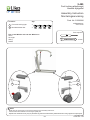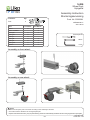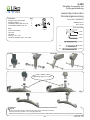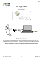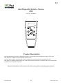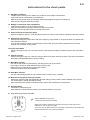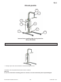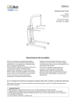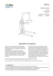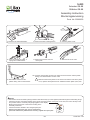
1
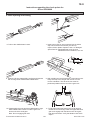
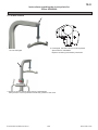
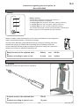
5.423
Actuator G8-88
Ställdon G8-88
Assembly Instruction
Monteringsanvisning
Prod. No. 20090078
13. Remove the mast attachment.
14. Remove the Em. lowering device.
15. Unfix the plastic cover.
16. Unfix the aluminium holder, 2
springs and 2 Slide blocks.
17. Remove the screws from the
motor plate.
18. Remove the inner mast.
20. Push the new actuator into the inner mast. Mount the screws and the plastic
casings, and reassemble in reverse order.
19. Remove the screws and the
plastic casing. Pull out the actuator.
Make sure the friction plates on the inner mast and the mast are in place.
If not; replace with Spare Part No. 20090072 Friction plates 2,8-3,4mm.
NOTE
- The actuator must be tested by lifting maximum load all the way up to the highest position/through the entire lifting range.
- Check the function of the limit switches in the upper and lower position. If they are out of order, the motor will stop in the
end position and the overload (orange light) lights on the display.
- Make sure the spare part is mounted according to the
assembly instruction.
- Check all functions related to the changed spare part.
- Repairs and maintenance may only be performed by
personnel authorized by Hill-Rom/Liko and using original Liko spare parts.
© Copyright Liko AB
82
www.liko.com
www.liko.com
5.485
Fork locking attachment
Låssats hjulgaffel
Assembly Instruction
Monteringsanvisning
Contains:
1
2
Prod. No. 20090080
Qty:
Front fork locking light
4
Nut M6LM M10 ISO
4
3SE690208-01
2011-09-23
Tools required
Fits 75 mm Wheels and 100 mm Wheels on:
Golvo
LikoLight
Viking
RollOn
16 mm
1
1
2
2
NOTE
- Make sure the spare part is mounted according to the assembly instruction.
- Check all functions related to the changed spare part.
- Repairs and maintenance may only be performed by personnel authorized by Hill-Rom/Liko and using original Liko spare parts.
© Copyright Liko AB
83
www.liko.com
www.liko.com
5.486
Wheel Fork
Hjulgaffel
Assembly Instruction
Monteringsanvisning
Contains:
Fork
Fits:
Qty:
Prod. No. 20090081
2
Front Wheel:
3SE690209-01
2011-09-28
Rear Wheel:
Golvo
X
X
Golvo LowBase
-
X
LikoLight
X
X
Viking XL
X
-
Viking L
X
-
Viking M
X
X
Viking S
X
X
Viking XS
X
X
RollOn
X
X
Tools required
16mm
4 mm
Assembly on front wheel:
Assembly on rear wheel:
NOTE
- Make sure the spare part is mounted according to the assembly instruction.
- Check all functions related to the changed spare part.
- Repairs and maintenance may only be performed by personnel authorized by Hill-Rom/Liko and using original Liko spare parts.
© Copyright Liko AB
84
www.liko.com
www.liko.com
5.487
Parking bracket
Parkeringsfäste
Assembly Instruction
Monteringsanvisning
Prod. No. 20090082
Contains:
Parking bracket
3SE690204-01
2011-09-20
Qty:
1
Fits:
Golvo
FreeSpan
FreeStand
NOTE
- Make sure the spare part is mounted according to the assembly instruction.
- Check all functions related to the changed spare part.
- Repairs and maintenance may only be performed by personnel authorized by Hill-Rom/Liko and using original Liko spare parts.
© Copyright Liko AB
85
www.liko.com
www.liko.com
5.490
SlingBar Assembly set
Lyftbygelinfästning
Assembly Instruction
Monteringsanvisning
Contains:
Slingbar bolt casing R2R
Slingbar Adapter
Threaded casing M6 10x16,5
Screw MRT M6x8 Ezloc A2
Qty:
1
1
1
2
Prod. No. 20490052
3SE690210-01
2011-09-26
Tools required
Fits:
Golvo (all models)
Uno 200
LikoLight
Viking L, M, S, XS
Universal Slingbar 350 / 450 / 600
4 mm
4 mm
6 mm
13 mm
Golvo
Uno 200
LikoLight
2x
10 mm
2x
17 mm
Viking
Tightening torque 11±1 Nm
NOTE
- Make sure the spare part is mounted according to the assembly instruction.
- Check all functions related to the changed spare part.
- Repairs and maintenance may only be performed by personnel authorized by Hill-Rom/Liko and using original Liko spare parts.
© Copyright Liko AB
86
www.liko.com
www.liko.com
5.492+496
Lift strap Cover Strip
Täckskiva grå
Assembly Instruction
Monteringsanvisning
20090085 Lift strap Cover Strip, 7007/8008
Contains:
Qty:
Lift strap Cover Strip, Golvo
1
Prod. No. 20090085, 20090087
3SE690212-01
2011-09-26
Fits:
Golvo 7007
Golvo 8008
20090087 Lift strap Cover Strip, 7000/8000
Contains:
Qty:
Lift strap Cover Strip, G
1
Tools required
Fits:
Golvo 7000
Golvo 8000
3 mm
Slide the Lift strap Cover strip in the
groove of the mast.
Assemble the side with the rough
structure facing out.
NOTE
- Make sure the spare part is mounted according to the assembly instruction.
- Check all functions related to the changed spare part.
- Repairs and maintenance may only be performed by personnel authorized by Hill-Rom/Liko and using original Liko spare parts.
© Copyright Liko AB
87
www.liko.com
www.liko.com
5.511
Locking Ring Hand Control CBL
Låsring för handkontroll CBL
Assembly Instruction
Monteringsanvisning
Contains:
Locking Ring
Fits:
Viking M
Viking L
Viking XL
Golvo 8000
Golvo 8008
Golvo 8008 LowBase
Qty:
10
Prod. No. 20490057
3SE690231-02
2013-01-17
Prod No.
2040035
2040034
2040033
2000034
2000035
2000039
Tools required
Press the triangular tab, then remove the locking ring
and the hand control
Triangular tab
facing out.
Connect the Hand control.
Attach the locking ring.
Make sure the rectangular tabs
at the locking ring are fixed.
NOTE
- Make sure the spare part is mounted according to the assembly instruction.
- Check all functions related to the changed spare part.
- Repairs and maintenance may only be performed by personnel authorized by Hill-Rom/Liko and using original Liko spare parts.
© Copyright Liko AB
88
www.liko.com
www.liko.com
PARAMETER Code Key
Liko Diagnostic System™ (operating data) is stored in Control Unit CBL
Parameter:
Information:
TAAxT [Ah]
Totally Accumulated Amphours (current x time)
TAAxTR [Ah]
Totally Accumulated Amphours, resetable (current x time)
Can be reset by the manufacturer.
PAAxT [Ah]
Periodically Accumulated Amphours (current x time)
Calculated continuously from the moment the lift is used until the
first service.
PAKT [Months]
Periodically Accumulated Calendar time.
Calculated between services.
TADT [Hours]
Totally accumulated drive time.
AAS [Starts]
Accumulated starts.
The number of lifting motions counted from the moment the lift was
used the first time.
ASERV [Services]
Accumulated services
Number of performed service events made using LSS or LDS.
IMED [A]
Average power consumption during TADT.
Overall accumulated operating time.
ALA [Charges]
Accumulatet number of started chargings.
AALA [Charges]
Accumulated number of completed chargings
AOLA [Charges]
Accumulated numbers of not completed charging.
Counts each disrupted charging event.
AABT [Removals]
Accumulated number of battery replacements.
Counts each battery replacement where a used battery is replaced.
AEUP [Endpos. up]
Accumulated number of end positions during lifting motion up.
AFSERV [Services]
Accumulated number of reset Service
Number of “Clear Service” performed manually.
6.1
Control Unit CBL
AEDWN [Endpos. down] Accumulated number of end positions during lifting motion down.
•
•
•
SFSTAT
N/A (This funktion is not in use)
IDNR
Identity number of the control box.
AOLUP [Overloads]
Accumulated number of stops due to overload.
PADT [Hours]
Periodically accumulated operating time.
IMED 20 [A]
Average current consumption. Recounted for each lifting motion
(up) which lasts more than 20 seconds.
ELT [Ah]
TAAxTR limit (constant) for ELT indication.
ELTCNT [Commands]
Number of ELT resets (only performed at replacement of actuator).
CLIM_1 [A]
Current limit for lifting motion (up).
CLCT [ms]
Maximum allowed time to override CLIM_1 before cut-off
CLIM_2 [A]
Current limit for widening motion (base-width adjustment).
SINTT [Months]
Indicates service intervals in calendar months.
SINTAS [Ah]
AxT limit for service event. (current x time)
CYCLET [Hours]
Cycle time is a constant for a medium driving cycle.
PAOLUP [Overloads]
Periodic accumulated number of stops due to overload.
The information listed above is stored in the Control Unit CBL.
Replacing the Control Unit CBL without using the LSS may cause some data loss as this data is recordable by
LSS and a computer. When data is stored in Liko database it can be retrieved if needed.
Resetting the Service Interval using the LSS, LDS or Manually, will reset the Accumulated Amp-hours (PAAxT),
Accumulated Time (PAKT), Accumulated Operating Time (PADT) and Accumulated number of stops due to
overload (PAOLUP).
89
www.liko.com
RESET SERVICE INTERVAL PARAMETERS
After the Periodic Inspection has been performed Service Light and Service Interval Parameters* in the Liko
Diagnostic System™ has to be reset. Reset can be done using one of the following Service Tools/Methods:
Prod. No.
21090024
6.2
1. Liko Service System, LSS (Requires a computer)
Read and store the data from the Control Unit CBL into a computer. Data can
also be transfered to a Liko Server. Can also reset the ELT-light (Expected Life Time).
Use when Periodic Inspection or Preventative maintenance is performed.
Service Documents for the lift can be printed. Use for tracking and and transfer
data when Spare Parts are changed.
Prod. No.
21090016
-
2. LDS Service (LDS)
Reads the data from the Control Unit CBL. Use when Periodic Inspection or
Preventative maintenance is performed.
3. Manual Service
Resets the Service Interval Parameters*.
Service Interval Parameters should only be reset after a complete Periodic Inspection
Use the following combination of buttons on the control panel:
A: Press and hold button 1 & 2
B: While holding 1 & 2, press button 3, and hold all three
buttons for three seconds.
1
2
3
(Works from Item No: CBL20001-05 on CBL (see label on CBL)
INPACT ON PARAMETERS
Changes of parameters when LSS, LDS or Manuel Service reset has been used:
Parameter:
Service Light *
1. LSS:
2. LDS:
Unlit
Unlit
3. Manual Service:
Check Points in PM ***
Unlit
TAAxT
unchanged
unchanged
unchanged
TAAxTR
unchanged
unchanged
unchanged
x ***
PAAxT **
0
0
0
PAKT **
0
0
0
TADT
unchanged
unchanged
unchanged
AAS
unchanged
unchanged
unchanged
x ***
ASERV
+1
+1
unchanged
x ***
IMED
unchanged
unchanged
unchanged
x ***
ALA
unchanged
unchanged
unchanged
x ***
AALA
unchanged
unchanged
unchanged
x ***
AOLA
unchanged
unchanged
unchanged
x ***
AABT
unchanged
unchanged
unchanged
x ***
AEUP
unchanged
unchanged
unchanged
x ***
AFSERV
0
0
+1
x ***
AEDWN
unchanged
unchanged
unchanged
x ***
SFSTAT
N/A
N/A
N/A
IDNR
unchanged
unchanged
unchanged
x ***
AOLUP
unchanged
unchanged
unchanged
x ***
PADT **
0
0
0
x ***
IMED20
unchanged
unchanged
unchanged
ELT
unchanged
unchanged
unchanged
ELTCNT
unchanged
unchanged
unchanged
CLIM1
unchanged
unchanged
unchanged
CLCT
unchanged
unchanged
unchanged
CLIM2
unchanged
unchanged
unchanged
SINTT
unchanged
unchanged
unchanged
SINTAS
unchanged
unchanged
unchanged
CYCLET
unchanged
unchanged
unchanged
PAOLUP **
0
0
0
x ***
x ***
* Indicates Service Periodic Inspection interval reached.
** Service Interval Parameters (the PAAxT, PAKT, PADT and PAOLUP are all used to determine Service intervals)
*** Parameters to use in the Preventative Maintenance
90
www.liko.com
7.0
Liko Service System
LSS
Prod. No. 21090024
Product Description
Liko Service System is a soft ware developed to enable service technicians to conduct service in an easy way
on all lifts equipped with the control unit CBL 20. It also gives the service technician the possibility to program the
spare part on the field.
Detailed information can be found in the instruction guide accompanying the product.
Liko Service System
91
www.liko.com
LDS Monitor/Service
8.0
Instruction Guide
English
7EN160198-01
2008-11-11
Liko Diagnostic System - Service
LDS
Prod. No. 21090016
Applies to the following models:
LDS Monitor
Prod. No. 2100016
LDS Service
Prod. No. 21090016
Product Description
Likolifts
liftsequipped
equippedwith
withLDS
LDS(Liko
(LikoDiagnostic
DiagnosticSystem™)
System™)recordLDS
is specially
Liko
and Service
store information
ondeveloped
how the liftforis Liko’s
used.
record
and store
information
oninformation
how the lift stored
is used.
authorized service technicians to reset the LDS
LDS
Service
is a reader
for LDS
in a lift.
LDS
Monitor
andcan
LDS
twocontrol
different
intervallifts
after
completed
The
LDS
Service
beService
used asare
hand
to models
operate Liko’sservice
IR controlled
equipped
withservice/periodic
LDS.
of readers for LDS information stored in a lift.
inspection.
LDS Service is specially developed for Liko’s authorized service technicians to reset the LDS service interval after
Both models
can be used inspection.
as hand control to operate
completed
service/periodic
Liko’s IR controlled lifts equipped with LDS.
Detailed information can be found in the instruction guide accompanying the product.
LDS Service
92
www.liko.com
9.0
Periodic Inspection
Golvo 8000
Golvo 8008
Golvo 8008
LowBase
Golvo 8000
Classic
Golvo 8008
Classic
2000014
2000015
2000019
2000024
2000025
2000034
2000035
2000039
Prod. No.
Output (TAAxT):
Ah
(Use Liko Service System or Liko Diagnostic System to read data from the CBL)
Customer references
Lift type:
.........................................................................
Agreement No: .....................................................
Prod. No:
.........................................................................
Name: ....................................................................
Serial No:
.........................................................................
Address: ................................................................
Prod. Year: .........................................................................
Post code: ............................................................
The lift must be thoroughly inspected when the Service Light at the Control Unit CBL iIluminates, or at least once per year.
Viking with other control unit shall be thoroughly inspected at least once per year. Inspection and service must be carried out
by Hill-Rom/Liko authorized personnel. Instructions for check points, from the next page.
Check points:
1
2
Approved
Product decal
Visible damage to the lift surface finish
Not
approved
To be actioned


..................................................................................
..................................................................................
Base
3
Castor wheels and forks
4
Castor brakes
5
Stop screw
6
Base opening and closing
7
Base attachment secure screw


..................................................................................
..................................................................................
..................................................................................
..................................................................................
..................................................................................
Mast
8
Armrest
9
Lift arm hardware and covers
10 Lift strap
11 SlingBar and latches
12 Battery and electrical cable installations
13 Hand control IR and operation panel
14 Emergency stop function
15 Control Unit CBL
16 Charger function


..................................................................................
..................................................................................
..................................................................................
..................................................................................
..................................................................................
..................................................................................
..................................................................................
..................................................................................
..................................................................................
Load Testing
17 Mast Max. load test
18 Base Max. load test
19 Mechanical emergency lowering load test


..................................................................................
..................................................................................
..................................................................................
Documentation
20 Instructions / Instruction guide
21 Clear Service (Control Unit CBL)


..................................................................................
..................................................................................
Approval to use the mobile lift
Approved
Not approved
Not approved:
If the mobile lift has one or more check points with result “Not approved” the mobile lift must not be used.
Inspection performed by: _____________________________________
Date:______________________
Final approval by:
________________________________________
Approval date: _____________
Next inspection:
________________________________________
Inspection performed in accordance with ISO 10535:2006 Annex B- Periodic inspection
Periodic Inspection
93
www.liko.com
2013-03-14
To be actioned:
Actions according to the “Instructions for the check points” should be performed immediatley. After performed actions sign
below. If anything is unclear or if you have questions, please contact Hill-Rom/Liko or your local Hill-Rom/Liko representative.
Contact information is to be found at www.liko.com.
9.0
Instructions for the check points
9
10
11
13
12
8
14 15
1
16
7
4
3
6
5
1 Product decal
- Verify presence of mast decal with model type and serial number.
2 Visible damage to the lift base and mast surface finish
- Check for scratches, dents, deformities or unusual surface wear.
3 Castor wheels and forks
- Roll the lift, unloaded and with load, along the floor. Check to ensure that all castors roll and turn freely.
- Verify that the castor fasteners are tight. There should not be any play between the fork and the castor nut.
4 Castor brakes
- Lock the brakes. Make sure the wheels do not turn and the castor housing does not swivel when the lift is pushed.
5 Stop screw
- Verify that the K6S M8x16 screw is secured with a nyloc nut inside the middle beam.
A
B
6 Base opening and closing
- Inspect telescoping insert beam for scratches/gouges
- Inspect that all hardware is tight.
- Verify max. & min. dimensions, according to the Service manual
- The distance A & B must be the same.
- The cover profiles (C) must be fixed to the middle beam (D).
D
7 Base attachment secure screw
C
- Verify that both locking screws are tight in base. In the upper holes on the mast.
- Note! Do not place any screws in the lower holes!
C
8
-
Armrest
Check for unusual scratches, dents or deformations.
Verify that both arms rotate freely and hang vertically when not in use. (Not Golvo Classic)
Rotate arms to raised position. (Not Golvo Classic)
Rotate arms to raised position, load the armrest with (40 kg/88 lbs). (Not Golvo Classic)
9
-
Lift arm hardware and covers
Inspect plastic lift arm cover for cracks and verify edges of cover are secured in groove of aluminium arm.
10 Lift strap
Using the hand control, lower the strap to its maximum extension. Inspect the belt for frayed edges, heavy
wrinkles or wear through areas.
Verify that Lift strap joint is secure on strap. Slide plastic cover off the Lift strap joint and visually inspect that
the lift strap safety pin is seated secure in the middle recess of the Q-link.
Periodic Inspection
94
www.liko.com
9.0
Instructions for the check points
11
-
SlingBar and latches
Visually inspect the sling bar to detect any scratches, sharp edges or deformities.
Check that the unit rotates freely on its bearings.
Make sure both latches clips are mounted and fall back against the body of the sling bar.
Verify that the sling bar fasteners are tight.
12
-
Battery and electrical cable installations
Inspect that the cable cover is mounted correctly.
Verify that all cables are properly inserted. Re insert if uncertain.
Make sure the charge cable hook is mounted at the mast.
13 Hand control IR and operation panel
- With the emergency stop out, verify that all functions on the hand control and the operation panel are working.
14 Emergency stop function.
Press in the emergency stop button. With the emergency stop pressed in, verify the lift does not operate with
the handcontrol buttons.
Turn the red emergency button in the direction of the arrows. Verify the button releases from the locked
position into the raised, open position.
15 Control unit CBL20
With the emergency stop out, verify the function of the electrical emergency-lowering device at the operation
panel.
16 Charger function
- With the emergency stop out, insert the charger cable into a power outlet (110-240V). The lamps should blink
alternately (orange/yellow/green) during charging.
17
-
Mast Max. load test
Run the lift with maximum load (205 kg / 450 lbs), all the way up and down.
Press right / left side to widen the base with maximum load.
Make sure all four wheels have contact with the floor.
Listen for peculiar noises and vibrations.
18 Base Max. load test
- Run the undercarriage (base) in and out with maximum load (140 kg / 308 lbs).
19
-
Mechanical emergency lowering load test
Raise with maximum load (205 kg/450 lbs) and with (50 kg/110 lbs) until the mast is parallel to the ground.
Lift red emergency handle upwards and hold.
After overcoming the internal mechanical brake, verify that the load lowers to the ground.
20 Documentation
Instructions / Instruction guide
Quick Reference Guide shall be placed in the intended holder on the mast.
21 Clear Service (Control Unit CBL)
Service indicator (orange light)
- Illuminates when service is needed.
When the Periodic Inspection has been performed, reset the service
indicator on the Control Unit CBL.
Use LSS, LDS or Manual Service according to instructions “Reset Service
Interval Parameters” in the Service Manual.
Periodic Inspection
95
www.liko.com
96
www.liko.com
10.0
Preventative Maintenance
Prod. No.
Golvo 8000
Golvo 8008
Golvo 8008
LowBase
Golvo 8000
Classic
Golvo 8008
Classic
2000014
2000015
2000019
2000024
2000025
2000034
2000035
2000039
Customer references
..............................................................
Agreement No: .......................................................
Product No: ..............................................................
Name: ......................................................................
Serial No:
..............................................................
Address: ..................................................................
Prod. Year: ..............................................................
Post code: ..............................................................
Lift type:
Use Liko Service System (LSS) or Liko Diagnostic System (LDS) to read data from Control Unit CBL. If you don’t have the
LSS, write down the values in the columns below. (With LSS you can store data)
TAAxT
Ah
AABT
Removals
PAAxT
Ah
AEUP
EposUp
AAS
Starts
AFSERV
Services
ASERV
Times
AEDWN
EposDn
IMED
mA
IDNR
ALA
Charges
AOLUP
OverLoads
AALA
Charges
PADT
Hours
AOLA
Charges
PAOLUP
OverLoads
To ensure maximum life cycle, Preventative Maintenance should be carried out according to how much the lift has been used
TAAxT (Totally Accumulated Amphours) or according to years in use, see table below. Inspection and service must be carried
out by Hill-Rom/Liko authorized personnel.
Check points:
Maintenance according to used TAAxT (Ah):
Maintenance according to years of use:
280
3
4
5
420
6
7
560
8
9
700
10
Surface treatment ..............................................
Front castors ....................................................
Rear castors / brakes ........................................
Base opening and closing .................................
Lift arm covers ...................................................
Lift strap.............................................................
Battery ...............................................................
Actuator replaced ..............................................
Control Unit CBL................................................
Lubricate with PTFE or silicon grease
When maintenance is performed; mark specified square with “X”
When part is replaced; mark specified square with “R”
2012-11-14
1
2
3
4
5
6
7
8
9
1
140
2
Interval/Month: _____________ Date: ____________ Serviced by: __________________________________
Preventative Maintenance
97
www.liko.com
10.0
Check points
5
6
9
8
7
4
3
2
Instructions regarding the check points for
Golvo 8000/8008
1 Surface treatment
1. Visually inspect the mast and base for external damage or wear.
If needed, clean the patient lift with warm water or ethanol.
Warning!
Do not use chemicals containing phenol or chlorine, since the aluminium parts may be damaged.
Preventative Maintenance
98
www.liko.com
10.0
Instructions regarding the check points for
Golvo 8000/8008
2 Front castors
1. Check and clean front castors.
2. If wheels are in poor condition, replace them with
Spare Part No. 20490014
(Front Castors to Golvo LowBase are included in Spare
Part No. 20090071 Low base kit Golvo 7007/8008)
Front castors needs to be replaced after:
or
Replace according to years in use:
700 Ah
10 years
3 Rear castors / brakes
1. Check and clean rear castors.
2. If wheels are in poor condition,
replace them with
Spare Part No. 20490015
Rear castors needs to be replaced after:
or
Replace according to years in use:
Preventative Maintenance
700 Ah
10 years
99
www.liko.com
10.0
Instructions regarding the check points for
Golvo 8000/8008
4. Base opening and closing
1. Adjust the legs in to wide position.
2. Disassemble the cover profiles and the stop screw.
3. Remove mast attachment screw from upper
holes and place in lower holes.
4. Remove the mast from the base by tightening the
screws against the base.
A
4. Remove plastic cover. Remove the stop screw and
nut. Remove base motor attachment screw.
Preventative Maintenance
B
5. Remove base motor from middle beam.
100
www.liko.com
10.0
Instructions regarding the check points for
Golvo 8000/8008
4. Base opening and closing
6. Pull out the middle beam inserts.
7. Inspect gear rack for worn teeth and cracks where
stop nut contacts back surface (see arrow).
Inspect friction plates. Replace if worn or damaged.
Spare Part No. 20090038 Gear rack set, and
20090072 Friction Plates 2,8-3,4 mm
8. Clean the friction plates/sliding surface and lubricate
with PTFE grease. Reassemble middle beam.
9. With middle beam at full extension, insert base motor.
Verify the stop screw is tight and the nut is in the
correct orientation. The flat of the hex must be
positioned parallel with the end of the gear rack.
G
A
10. Reassemble the mast and the middle beam to legs.
Slide middle beam inserts in until the gear rack
touches the drive shaft gear.
Note: Do not engage gear rack!
Preventative Maintenance
B
D
11. To set base width start
Cbase motor while applying
inword force on both legs. After the upper and lower
101
gear rack engage with the base motor drive gear,
both legs will retract. Verify that distance A & B are
equal.
www.liko.com
10.0
Instructions regarding the check points for
Golvo 8000/8008
5. Lift Arm Covers
1. Check to ensure that Roll Frame Attachment covers
are not damaged.
2. If damaged, the Roll Frame must be replaced.
Spare Part No. 20090064
Replace according to assembly instruction.
3. Check to ensure that lift strap cover is not damaged.
Verify that the cover is positioned inside the grooves of the mast.
Preventative Maintenance
102
www.liko.com
10.0
Instructions regarding the check points for
Golvo 8000/8008
6. Liftstrap
1. Check the lift strap by driving the lift up & down.
2. Check the strap inside the emergency lowering device.
Easy strapper:
Lift strap:
3. Push the emergency lowering handle down and
pull the strap away.
Liftstrap needs to be replaced after:
or
Replace according to years in use:
Preventative Maintenance
4. If the lift strap is damaged or worn, it should be
replaced with lift strap according to Spare Parts List
and assembly instruction for the spare part.
280 Ah
and
560 Ah
4 years
and
8 years
103
www.liko.com
10.0
Instructions regarding the check points for
Golvo 8000/8008
7. Battery
2
3
4
Battery capacity
Check battery capacity by pressing the i button (1).
The following information is displayed:
2 – Green light: More than 50% of battery capacity remaining.
3 – Yellow light: 25% -50% of battery capacity remaining.
4 – Yellow light: 0% -25% of battery capacity remaining.
The indicator lamps light for about 30 seconds before switching off.
Battery capacity is also displayed during lift operation.
1
Maximum charge is reached after about 5 hours. When the batteries are fully charged, the
charger switches automatically to maintenance charging.
The lamps blink alternately (yellow/yellow/green) during charging. A blinking green lamp
indicates that charging is complete. When operating time is noticeably shorter than
normal, the batteries should probably be replaced. Discontinue charging and replace the
batteries with Product No. 2006107 Extra battery box.
Batteries needs to be replaced after:
or
Replace according to years in use:
280 Ah
and
560 Ah
4 years
and
8 years
8. Actuator
Replace the actuator with Spare Part No. 20090078
Actuator needs to be replaced after:
or
Replace according to years in use:
Preventative Maintenance
700 Ah
10 years
104
www.liko.com
Instructions regarding the check points for
Golvo 8000/8008
10.0
9 Control Unit CBL
Use LSS or LDS to check that the correct current limit is programmed in CBL20:
CLIM_1
CLIM_2
Power limit for lifting motion (up) Power limit for widening motion
(actuator)
(base motor)
8,2 [A]
Preventative Maintenance
6 [A]
105
www.liko.com
106
www.liko.com
11.0
Golvo
Product changes
Prod. No. 2000014
2000015 2000019
2000024
2000025
Changes
Golvo with fixed hand control:
Prod. No. 2000034 Golvo 8000
Golvo 8000
2000035 Golvo 8008
Golvo 8008 2000039 Golvo 8008 LowBase
Golvo 8008 LowBase
Golvo 8000 Classic
2012-11-16
Golvo 8008 Classic
Model
2000014
from S/N:
Model
2000015
from S/N:
Model
2000019
from S/N:
Model
2000024
from S/N:
Model
2000025
from S/N:
Model
2000034
from S/N:
Model
2000035
from S/N:
Model
2000039
from S/N:
Proj.
5 460 001
5 560 001
5 660 001
1707
2013
New models of Golvo with fixed
handcontrol on CBL20 control unit,
are introduced.
2010
New models of Golvo with CBL20
control unit, are intruduced.
www.liko.com
5 000 000
5 100 001
5 200 001
107
5 220 001
5 240 001
490
w w w . l i k o . com
Manufacturer:
Liko AB
SE-975 92 Luleå
Sweden
[email protected]