1
GE Healthcare
PROCARE* Monitor B40/B20
Technical Reference Manual
PROCARE Monitor B40/B20
English
2050802-001 C (Paper)
© 2011 General Electric Company.
All Rights Reserved.
PROCARE Monitor B40/B20
Technical Reference Manual
0459
Conformity according to the Council Directive 93/42/EEC concerning Medical Devices
All specifications subject to change without notice.
Order code 2050802-001
Revision C
13 June, 2011
GE Medical Systems Information Technologies, Inc.
8200 West Tower Avenue
Milwaukee, WI USA
Zip: 53223
Tel: 1 414 355 5000 (outside US)
800 558 5102 (US only)
Fax: 1 414 355 3790
www.gehealthcare.com
Copyright 2011 General Electric Company. All rights reserved.
GE Healthcare
3F Building 1, GE Technology Park
1 Huatuo Road
Shanghai PRC 201203
Tel: +86 21 3877 7888
Fax: +86 21 3877 7451
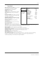
Classifications
In accordance with IEC 60601-1
Class I and internally powered equipment - the type of protection against electric shock.
Type BF or CF equipment. The degree of protection against electric shock is indicated by
a symbol on each parameter module.
Equipment is not suitable for use in the presence of a flammable anesthetic mixture with
air or with oxygen or nitrous oxide.
Continuous operation according to the mode of operation.
Portable Monitor
In accordance with IEC 60529
IP21 - degree of protection against harmful ingress of water.
In accordance with EU Medical Device Directive
IIb.
In accordance with CISPR 11:
Group 1 Class A;
•
Group 1 contains all ISM (Industrial, scientific and medical) equipment in which there
is intentionally generated and/or used conductively coupled radio-frequency
energy which is necessary for the internal functioning of the equipment itself.
•
Class A equipment is equipment suitable for use in all establishments other than
domestic and those directly connected to a low-voltage power supply network
which supplies buildings used for domestic purposes.
Trademarks
Dash, ProCare, DINAMAP, EK-Pro, Trim Knob, Unity Network, Datex, Ohmeda, S/5, D-fend,
D-fend+, Mini D-fend, OxyTip+, EarSat, FingerSat, FlexSat are trademarks of GE Healthcare. All
other product and company names are property of their respective owners.
1
Introduction
About this manual
1
1
3
Overview
1.1
1.2
1.3
2
3
System description
11
2.1
2.2
2.3
2.4
2.5
2.6
11
11
12
12
12
13
Introduction . . . . . . . . . . . . . . . . . . . . . . . . . . . . . . . . . . . . . . . . . . . . . . . . . . . . . . . . . . . . . . . . . . . . . . . . . .
Bus structure . . . . . . . . . . . . . . . . . . . . . . . . . . . . . . . . . . . . . . . . . . . . . . . . . . . . . . . . . . . . . . . . . . . . . . . . .
Distributed processing . . . . . . . . . . . . . . . . . . . . . . . . . . . . . . . . . . . . . . . . . . . . . . . . . . . . . . . . . . . . . . . .
Module communication. . . . . . . . . . . . . . . . . . . . . . . . . . . . . . . . . . . . . . . . . . . . . . . . . . . . . . . . . . . . . . .
Software loading . . . . . . . . . . . . . . . . . . . . . . . . . . . . . . . . . . . . . . . . . . . . . . . . . . . . . . . . . . . . . . . . . . . . .
Parameter modules . . . . . . . . . . . . . . . . . . . . . . . . . . . . . . . . . . . . . . . . . . . . . . . . . . . . . . . . . . . . . . . . . .
Frame functional description
14
3.1
14
14
14
16
17
19
19
19
20
20
3.2
3.3
4
Symbols . . . . . . . . . . . . . . . . . . . . . . . . . . . . . . . . . . . . . . . . . . . . . . . . . . . . . . . . . . . . . . . . . . . . . . . . . . . . . . 4
Safety information. . . . . . . . . . . . . . . . . . . . . . . . . . . . . . . . . . . . . . . . . . . . . . . . . . . . . . . . . . . . . . . . . . . . . 8
1.2.1 General . . . . . . . . . . . . . . . . . . . . . . . . . . . . . . . . . . . . . . . . . . . . . . . . . . . . . . . . . . . . . . . . . . . . . . . . . 8
1.2.2 Safety message signal words. . . . . . . . . . . . . . . . . . . . . . . . . . . . . . . . . . . . . . . . . . . . . . . . . . . . 8
1.2.3 Safety precautions . . . . . . . . . . . . . . . . . . . . . . . . . . . . . . . . . . . . . . . . . . . . . . . . . . . . . . . . . . . . . . 8
1.2.4 ESD precautionary procedures . . . . . . . . . . . . . . . . . . . . . . . . . . . . . . . . . . . . . . . . . . . . . . . . . . 9
1.2.5 Disposal . . . . . . . . . . . . . . . . . . . . . . . . . . . . . . . . . . . . . . . . . . . . . . . . . . . . . . . . . . . . . . . . . . . . . . . 10
Service information . . . . . . . . . . . . . . . . . . . . . . . . . . . . . . . . . . . . . . . . . . . . . . . . . . . . . . . . . . . . . . . . . . . 10
1.3.1 Service requirements. . . . . . . . . . . . . . . . . . . . . . . . . . . . . . . . . . . . . . . . . . . . . . . . . . . . . . . . . . . 10
1.3.2 Equipment identification . . . . . . . . . . . . . . . . . . . . . . . . . . . . . . . . . . . . . . . . . . . . . . . . . . . . . . . 10
Main components . . . . . . . . . . . . . . . . . . . . . . . . . . . . . . . . . . . . . . . . . . . . . . . . . . . . . . . . . . . . . . . . . . . .
3.1.1 Keyboards. . . . . . . . . . . . . . . . . . . . . . . . . . . . . . . . . . . . . . . . . . . . . . . . . . . . . . . . . . . . . . . . . . . . .
3.1.2 Display . . . . . . . . . . . . . . . . . . . . . . . . . . . . . . . . . . . . . . . . . . . . . . . . . . . . . . . . . . . . . . . . . . . . . . . .
3.1.3 CPU board . . . . . . . . . . . . . . . . . . . . . . . . . . . . . . . . . . . . . . . . . . . . . . . . . . . . . . . . . . . . . . . . . . . . .
3.1.4 Power board . . . . . . . . . . . . . . . . . . . . . . . . . . . . . . . . . . . . . . . . . . . . . . . . . . . . . . . . . . . . . . . . . .
3.1.5 AC/DC unit . . . . . . . . . . . . . . . . . . . . . . . . . . . . . . . . . . . . . . . . . . . . . . . . . . . . . . . . . . . . . . . . . . . .
3.1.6 Batteries. . . . . . . . . . . . . . . . . . . . . . . . . . . . . . . . . . . . . . . . . . . . . . . . . . . . . . . . . . . . . . . . . . . . . . .
Interfacing computer . . . . . . . . . . . . . . . . . . . . . . . . . . . . . . . . . . . . . . . . . . . . . . . . . . . . . . . . . . . . . . . . .
Connectors and signals . . . . . . . . . . . . . . . . . . . . . . . . . . . . . . . . . . . . . . . . . . . . . . . . . . . . . . . . . . . . . . .
3.3.1 External connectors. . . . . . . . . . . . . . . . . . . . . . . . . . . . . . . . . . . . . . . . . . . . . . . . . . . . . . . . . . . .
Hemo-dynamic module introduction
23
4.1
4.2
23
23
23
24
26
28
29
35
36
36
38
38
38
38
40
40
41
4.3
4.4
Monitor software compatibility . . . . . . . . . . . . . . . . . . . . . . . . . . . . . . . . . . . . . . . . . . . . . . . . . . . . . . . .
Main components . . . . . . . . . . . . . . . . . . . . . . . . . . . . . . . . . . . . . . . . . . . . . . . . . . . . . . . . . . . . . . . . . . . .
4.2.1 Hemo-dynamic module . . . . . . . . . . . . . . . . . . . . . . . . . . . . . . . . . . . . . . . . . . . . . . . . . . . . . . . .
4.2.2 NIBP board . . . . . . . . . . . . . . . . . . . . . . . . . . . . . . . . . . . . . . . . . . . . . . . . . . . . . . . . . . . . . . . . . . . .
4.2.3 ECG board in 5-lead measurement. . . . . . . . . . . . . . . . . . . . . . . . . . . . . . . . . . . . . . . . . . . . . .
4.2.4 ECG filtering . . . . . . . . . . . . . . . . . . . . . . . . . . . . . . . . . . . . . . . . . . . . . . . . . . . . . . . . . . . . . . . . . . .
4.2.5 STP board . . . . . . . . . . . . . . . . . . . . . . . . . . . . . . . . . . . . . . . . . . . . . . . . . . . . . . . . . . . . . . . . . . . . .
4.2.6 Power supply . . . . . . . . . . . . . . . . . . . . . . . . . . . . . . . . . . . . . . . . . . . . . . . . . . . . . . . . . . . . . . . . . .
Connectors and signals . . . . . . . . . . . . . . . . . . . . . . . . . . . . . . . . . . . . . . . . . . . . . . . . . . . . . . . . . . . . . . .
4.3.1 Front panel connectors. . . . . . . . . . . . . . . . . . . . . . . . . . . . . . . . . . . . . . . . . . . . . . . . . . . . . . . . .
Measurement principle . . . . . . . . . . . . . . . . . . . . . . . . . . . . . . . . . . . . . . . . . . . . . . . . . . . . . . . . . . . . . . .
4.4.1 NIBP. . . . . . . . . . . . . . . . . . . . . . . . . . . . . . . . . . . . . . . . . . . . . . . . . . . . . . . . . . . . . . . . . . . . . . . . . . .
4.4.2 ECG . . . . . . . . . . . . . . . . . . . . . . . . . . . . . . . . . . . . . . . . . . . . . . . . . . . . . . . . . . . . . . . . . . . . . . . . . . .
4.4.3 Pulse oximetry . . . . . . . . . . . . . . . . . . . . . . . . . . . . . . . . . . . . . . . . . . . . . . . . . . . . . . . . . . . . . . . . .
4.4.4 Temperature. . . . . . . . . . . . . . . . . . . . . . . . . . . . . . . . . . . . . . . . . . . . . . . . . . . . . . . . . . . . . . . . . . .
4.4.5 Invasive blood pressure . . . . . . . . . . . . . . . . . . . . . . . . . . . . . . . . . . . . . . . . . . . . . . . . . . . . . . . .
4.4.6 Respiration . . . . . . . . . . . . . . . . . . . . . . . . . . . . . . . . . . . . . . . . . . . . . . . . . . . . . . . . . . . . . . . . . . . .
i
Document no. 2050802-001
B40/B20 Patient Monitor
2
Hardware installation
1
Hardware installation
1
1.1
1.2
1.3
1.4
1
1
1
2
2
2
3
3
5
6
7
7
1.5
1.6
1.7
1.8
1.9
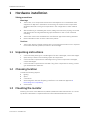
3
Unpacking instructions . . . . . . . . . . . . . . . . . . . . . . . . . . . . . . . . . . . . . . . . . . . . . . . . . . . . . . . . . . . . . . . .
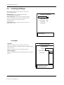
Choosing location . . . . . . . . . . . . . . . . . . . . . . . . . . . . . . . . . . . . . . . . . . . . . . . . . . . . . . . . . . . . . . . . . . . . .
Mounting the monitor. . . . . . . . . . . . . . . . . . . . . . . . . . . . . . . . . . . . . . . . . . . . . . . . . . . . . . . . . . . . . . . . . .
Connection to mains. . . . . . . . . . . . . . . . . . . . . . . . . . . . . . . . . . . . . . . . . . . . . . . . . . . . . . . . . . . . . . . . . . .
1.4.1 Install the batteries. . . . . . . . . . . . . . . . . . . . . . . . . . . . . . . . . . . . . . . . . . . . . . . . . . . . . . . . . . . . . .
Connection to Network . . . . . . . . . . . . . . . . . . . . . . . . . . . . . . . . . . . . . . . . . . . . . . . . . . . . . . . . . . . . . . . .
1.5.1 Pre-installation requirements . . . . . . . . . . . . . . . . . . . . . . . . . . . . . . . . . . . . . . . . . . . . . . . . . . . .
1.5.2 Network configuration . . . . . . . . . . . . . . . . . . . . . . . . . . . . . . . . . . . . . . . . . . . . . . . . . . . . . . . . . .
Inserting and removing the E-miniC module . . . . . . . . . . . . . . . . . . . . . . . . . . . . . . . . . . . . . . . . . . . .
Monitor connections . . . . . . . . . . . . . . . . . . . . . . . . . . . . . . . . . . . . . . . . . . . . . . . . . . . . . . . . . . . . . . . . . .
Visual indicators. . . . . . . . . . . . . . . . . . . . . . . . . . . . . . . . . . . . . . . . . . . . . . . . . . . . . . . . . . . . . . . . . . . . . . .
Installation checkout. . . . . . . . . . . . . . . . . . . . . . . . . . . . . . . . . . . . . . . . . . . . . . . . . . . . . . . . . . . . . . . . . . .
Maintenance
1
Instructions
1.1
1.2
2
Electrical Safety Tests
2.1
2.2
2.3
2.4
2.5
2.6
2.7
2.8
2.9
2.10
2.11
3
4
1
Introduction . . . . . . . . . . . . . . . . . . . . . . . . . . . . . . . . . . . . . . . . . . . . . . . . . . . . . . . . . . . . . . . . . . . . . . . . . . . 1
Recommended tools. . . . . . . . . . . . . . . . . . . . . . . . . . . . . . . . . . . . . . . . . . . . . . . . . . . . . . . . . . . . . . . . . . . 2
3
General. . . . . . . . . . . . . . . . . . . . . . . . . . . . . . . . . . . . . . . . . . . . . . . . . . . . . . . . . . . . . . . . . . . . . . . . . . . . . . . . 3
Recommendations . . . . . . . . . . . . . . . . . . . . . . . . . . . . . . . . . . . . . . . . . . . . . . . . . . . . . . . . . . . . . . . . . . . . 3
Test Equipment . . . . . . . . . . . . . . . . . . . . . . . . . . . . . . . . . . . . . . . . . . . . . . . . . . . . . . . . . . . . . . . . . . . . . . . . 3
Power Outlet Test. . . . . . . . . . . . . . . . . . . . . . . . . . . . . . . . . . . . . . . . . . . . . . . . . . . . . . . . . . . . . . . . . . . . . . 3
Power cord and plug. . . . . . . . . . . . . . . . . . . . . . . . . . . . . . . . . . . . . . . . . . . . . . . . . . . . . . . . . . . . . . . . . . . 4
Ground (Earth) Integrity . . . . . . . . . . . . . . . . . . . . . . . . . . . . . . . . . . . . . . . . . . . . . . . . . . . . . . . . . . . . . . . . 4
2.6.1 Ground Continuity Test . . . . . . . . . . . . . . . . . . . . . . . . . . . . . . . . . . . . . . . . . . . . . . . . . . . . . . . . . . 4
2.6.2 Impedance of Protective Earth Connection . . . . . . . . . . . . . . . . . . . . . . . . . . . . . . . . . . . . . . . 5
Ground (earth) wire leakage current tests . . . . . . . . . . . . . . . . . . . . . . . . . . . . . . . . . . . . . . . . . . . . . . . 5
Enclosure (Touch) leakage current test. . . . . . . . . . . . . . . . . . . . . . . . . . . . . . . . . . . . . . . . . . . . . . . . . . 7
Patient (source) leakage current test. . . . . . . . . . . . . . . . . . . . . . . . . . . . . . . . . . . . . . . . . . . . . . . . . . . . 9
Patient (sink) leakage current test . . . . . . . . . . . . . . . . . . . . . . . . . . . . . . . . . . . . . . . . . . . . . . . . . . . . . 10
Test completion . . . . . . . . . . . . . . . . . . . . . . . . . . . . . . . . . . . . . . . . . . . . . . . . . . . . . . . . . . . . . . . . . . . . . . 12
Installation checkout
13
3.1
3.2
13
13
13
14
14
14
14
14
15
Visual inspection . . . . . . . . . . . . . . . . . . . . . . . . . . . . . . . . . . . . . . . . . . . . . . . . . . . . . . . . . . . . . . . . . . . . .
Functional inspection . . . . . . . . . . . . . . . . . . . . . . . . . . . . . . . . . . . . . . . . . . . . . . . . . . . . . . . . . . . . . . . . .
3.2.1 Start-up . . . . . . . . . . . . . . . . . . . . . . . . . . . . . . . . . . . . . . . . . . . . . . . . . . . . . . . . . . . . . . . . . . . . . . .
3.2.2 Display . . . . . . . . . . . . . . . . . . . . . . . . . . . . . . . . . . . . . . . . . . . . . . . . . . . . . . . . . . . . . . . . . . . . . . . .
3.2.3 Frame unit. . . . . . . . . . . . . . . . . . . . . . . . . . . . . . . . . . . . . . . . . . . . . . . . . . . . . . . . . . . . . . . . . . . . .
3.2.4 Parameters measurements. . . . . . . . . . . . . . . . . . . . . . . . . . . . . . . . . . . . . . . . . . . . . . . . . . . . .
3.2.5 Recorder . . . . . . . . . . . . . . . . . . . . . . . . . . . . . . . . . . . . . . . . . . . . . . . . . . . . . . . . . . . . . . . . . . . . . .
3.2.6 Network connection. . . . . . . . . . . . . . . . . . . . . . . . . . . . . . . . . . . . . . . . . . . . . . . . . . . . . . . . . . . .
3.2.7 Conclusion. . . . . . . . . . . . . . . . . . . . . . . . . . . . . . . . . . . . . . . . . . . . . . . . . . . . . . . . . . . . . . . . . . . . .
Maintenance and checkout
4.1
16
Visual inspection/preparation . . . . . . . . . . . . . . . . . . . . . . . . . . . . . . . . . . . . . . . . . . . . . . . . . . . . . . . . . 16
4.1.1 Before beginning. . . . . . . . . . . . . . . . . . . . . . . . . . . . . . . . . . . . . . . . . . . . . . . . . . . . . . . . . . . . . . . 16
4.1.2 General . . . . . . . . . . . . . . . . . . . . . . . . . . . . . . . . . . . . . . . . . . . . . . . . . . . . . . . . . . . . . . . . . . . . . . . . 16
ii
Document no. 2050802-001
4.2
5
Adjustments and calibrations
5.1
5.2
5.3
4
16
16
17
17
17
17
21
21
21
21
22
22
23
NIBP calibrations . . . . . . . . . . . . . . . . . . . . . . . . . . . . . . . . . . . . . . . . . . . . . . . . . . . . . . . . . . . . . . . . . . . . . 23
Temperature calibration . . . . . . . . . . . . . . . . . . . . . . . . . . . . . . . . . . . . . . . . . . . . . . . . . . . . . . . . . . . . . . 24
Invasive pressure calibration . . . . . . . . . . . . . . . . . . . . . . . . . . . . . . . . . . . . . . . . . . . . . . . . . . . . . . . . . . 25
Troubleshooting
1
Introduction
1.1
1.2
2
3
3.5
3.6
3.7
3.8
3.9
4
NET section troubleshooting . . . . . . . . . . . . . . . . . . . . . . . . . . . . . . . . . . . . . . . . . . . . . . . . . . . . . . . . . . . 6
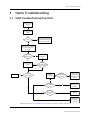
Hemo Troubleshooting
3.1
3.2
3.3
3.4
1
General troubleshooting . . . . . . . . . . . . . . . . . . . . . . . . . . . . . . . . . . . . . . . . . . . . . . . . . . . . . . . . . . . . . . . 2
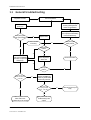
Software troubleshooting chart . . . . . . . . . . . . . . . . . . . . . . . . . . . . . . . . . . . . . . . . . . . . . . . . . . . . . . . . 3
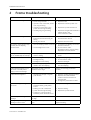
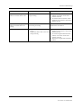
Frame troubleshooting
2.1
5
Functional inspection . . . . . . . . . . . . . . . . . . . . . . . . . . . . . . . . . . . . . . . . . . . . . . . . . . . . . . . . . . . . . . . . .
4.2.1 General . . . . . . . . . . . . . . . . . . . . . . . . . . . . . . . . . . . . . . . . . . . . . . . . . . . . . . . . . . . . . . . . . . . . . . . .
4.2.2 Display . . . . . . . . . . . . . . . . . . . . . . . . . . . . . . . . . . . . . . . . . . . . . . . . . . . . . . . . . . . . . . . . . . . . . . . .
4.2.3 Keyboard(s). . . . . . . . . . . . . . . . . . . . . . . . . . . . . . . . . . . . . . . . . . . . . . . . . . . . . . . . . . . . . . . . . . . .
4.2.4 Time and date . . . . . . . . . . . . . . . . . . . . . . . . . . . . . . . . . . . . . . . . . . . . . . . . . . . . . . . . . . . . . . . . .
4.2.5 Hemo Module. . . . . . . . . . . . . . . . . . . . . . . . . . . . . . . . . . . . . . . . . . . . . . . . . . . . . . . . . . . . . . . . . .
4.2.6 Loudspeaker. . . . . . . . . . . . . . . . . . . . . . . . . . . . . . . . . . . . . . . . . . . . . . . . . . . . . . . . . . . . . . . . . . .
4.2.7 Monitor software. . . . . . . . . . . . . . . . . . . . . . . . . . . . . . . . . . . . . . . . . . . . . . . . . . . . . . . . . . . . . . .
4.2.8 Watchdog circuitry . . . . . . . . . . . . . . . . . . . . . . . . . . . . . . . . . . . . . . . . . . . . . . . . . . . . . . . . . . . .
4.2.9 Batteries. . . . . . . . . . . . . . . . . . . . . . . . . . . . . . . . . . . . . . . . . . . . . . . . . . . . . . . . . . . . . . . . . . . . . . .
4.2.10 Network . . . . . . . . . . . . . . . . . . . . . . . . . . . . . . . . . . . . . . . . . . . . . . . . . . . . . . . . . . . . . . . . . . . . . . .
4.2.11 Final cleaning . . . . . . . . . . . . . . . . . . . . . . . . . . . . . . . . . . . . . . . . . . . . . . . . . . . . . . . . . . . . . . . . . .
7
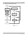
NIBP troubleshooting flowchart . . . . . . . . . . . . . . . . . . . . . . . . . . . . . . . . . . . . . . . . . . . . . . . . . . . . . . . . 7
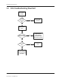
ECG troubleshooting flowchart . . . . . . . . . . . . . . . . . . . . . . . . . . . . . . . . . . . . . . . . . . . . . . . . . . . . . . . . . 8
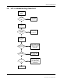
STP troubleshooting flowchart . . . . . . . . . . . . . . . . . . . . . . . . . . . . . . . . . . . . . . . . . . . . . . . . . . . . . . . . . 9
NIBP . . . . . . . . . . . . . . . . . . . . . . . . . . . . . . . . . . . . . . . . . . . . . . . . . . . . . . . . . . . . . . . . . . . . . . . . . . . . . . . . . 10
3.4.1 NIBP toubleshooting . . . . . . . . . . . . . . . . . . . . . . . . . . . . . . . . . . . . . . . . . . . . . . . . . . . . . . . . . . . 10
3.4.2 NIBP error code explanation . . . . . . . . . . . . . . . . . . . . . . . . . . . . . . . . . . . . . . . . . . . . . . . . . . . . 12
ECG . . . . . . . . . . . . . . . . . . . . . . . . . . . . . . . . . . . . . . . . . . . . . . . . . . . . . . . . . . . . . . . . . . . . . . . . . . . . . . . . . . 13
Impedance respiration . . . . . . . . . . . . . . . . . . . . . . . . . . . . . . . . . . . . . . . . . . . . . . . . . . . . . . . . . . . . . . . . 14
Pulse oximetry (SpO2). . . . . . . . . . . . . . . . . . . . . . . . . . . . . . . . . . . . . . . . . . . . . . . . . . . . . . . . . . . . . . . . . 15
Temperature . . . . . . . . . . . . . . . . . . . . . . . . . . . . . . . . . . . . . . . . . . . . . . . . . . . . . . . . . . . . . . . . . . . . . . . . . 16
Invasive blood pressure . . . . . . . . . . . . . . . . . . . . . . . . . . . . . . . . . . . . . . . . . . . . . . . . . . . . . . . . . . . . . . . 16
Service Menu
1
Introduction
1.1
1.2
2
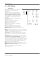
SW Management
2.1
2.2
2.3
1
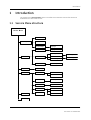
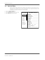
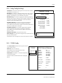
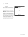
Service Menu structure . . . . . . . . . . . . . . . . . . . . . . . . . . . . . . . . . . . . . . . . . . . . . . . . . . . . . . . . . . . . . . . . 1
Service Menu . . . . . . . . . . . . . . . . . . . . . . . . . . . . . . . . . . . . . . . . . . . . . . . . . . . . . . . . . . . . . . . . . . . . . . . . . . 2
3
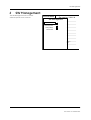
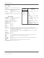
SW Download . . . . . . . . . . . . . . . . . . . . . . . . . . . . . . . . . . . . . . . . . . . . . . . . . . . . . . . . . . . . . . . . . . . . . . . . . 4
Active Inactive SW . . . . . . . . . . . . . . . . . . . . . . . . . . . . . . . . . . . . . . . . . . . . . . . . . . . . . . . . . . . . . . . . . . . . . 4
Country Settings. . . . . . . . . . . . . . . . . . . . . . . . . . . . . . . . . . . . . . . . . . . . . . . . . . . . . . . . . . . . . . . . . . . . . . . 4
iii
Document no. 2050802-001
B40/B20 Patient Monitor
3
Frame
3.1
3.2
3.3
4
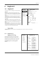
Keyboard
4.1
4
17
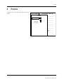
Keyboard . . . . . . . . . . . . . . . . . . . . . . . . . . . . . . . . . . . . . . . . . . . . . . . . . . . . . . . . . . . . . . . . . . . . . . . . . . . . 17
4.1.1 Keyboard Log. . . . . . . . . . . . . . . . . . . . . . . . . . . . . . . . . . . . . . . . . . . . . . . . . . . . . . . . . . . . . . . . . . 17
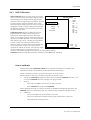
Parameters
18
4.1
19
19
20
21
22
23
25
26
27
29
30
31
4.2
4.3
4.4
4.5
6
5
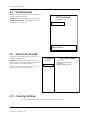
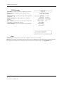
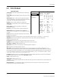
Country Settings. . . . . . . . . . . . . . . . . . . . . . . . . . . . . . . . . . . . . . . . . . . . . . . . . . . . . . . . . . . . . . . . . . . . . . . 6
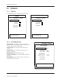
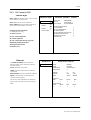
Network. . . . . . . . . . . . . . . . . . . . . . . . . . . . . . . . . . . . . . . . . . . . . . . . . . . . . . . . . . . . . . . . . . . . . . . . . . . . . . . 8
3.2.1 Network . . . . . . . . . . . . . . . . . . . . . . . . . . . . . . . . . . . . . . . . . . . . . . . . . . . . . . . . . . . . . . . . . . . . . . . . 8
3.2.2 Dri Config (in S/5) . . . . . . . . . . . . . . . . . . . . . . . . . . . . . . . . . . . . . . . . . . . . . . . . . . . . . . . . . . . . . . . 8
3.2.3 Dri Comm (in S/5) . . . . . . . . . . . . . . . . . . . . . . . . . . . . . . . . . . . . . . . . . . . . . . . . . . . . . . . . . . . . . . . 9
3.2.4 Unity Config (in Unity) . . . . . . . . . . . . . . . . . . . . . . . . . . . . . . . . . . . . . . . . . . . . . . . . . . . . . . . . . . 11
3.2.5 TCP/IP Config . . . . . . . . . . . . . . . . . . . . . . . . . . . . . . . . . . . . . . . . . . . . . . . . . . . . . . . . . . . . . . . . . . 11
Power supply . . . . . . . . . . . . . . . . . . . . . . . . . . . . . . . . . . . . . . . . . . . . . . . . . . . . . . . . . . . . . . . . . . . . . . . . 13
3.3.1 WPM Battery . . . . . . . . . . . . . . . . . . . . . . . . . . . . . . . . . . . . . . . . . . . . . . . . . . . . . . . . . . . . . . . . . . 14
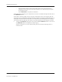
Gas Unit . . . . . . . . . . . . . . . . . . . . . . . . . . . . . . . . . . . . . . . . . . . . . . . . . . . . . . . . . . . . . . . . . . . . . . . . . . . . . .
4.1.1 General . . . . . . . . . . . . . . . . . . . . . . . . . . . . . . . . . . . . . . . . . . . . . . . . . . . . . . . . . . . . . . . . . . . . . . . .
4.1.2 Gases. . . . . . . . . . . . . . . . . . . . . . . . . . . . . . . . . . . . . . . . . . . . . . . . . . . . . . . . . . . . . . . . . . . . . . . . . .
ECG Module . . . . . . . . . . . . . . . . . . . . . . . . . . . . . . . . . . . . . . . . . . . . . . . . . . . . . . . . . . . . . . . . . . . . . . . . . .
4.2.1 ECG Setup . . . . . . . . . . . . . . . . . . . . . . . . . . . . . . . . . . . . . . . . . . . . . . . . . . . . . . . . . . . . . . . . . . . . .
STP Module (for GE SpO2) . . . . . . . . . . . . . . . . . . . . . . . . . . . . . . . . . . . . . . . . . . . . . . . . . . . . . . . . . . . . .
4.3.1 Calibrations. . . . . . . . . . . . . . . . . . . . . . . . . . . . . . . . . . . . . . . . . . . . . . . . . . . . . . . . . . . . . . . . . . . .
NIBP Module . . . . . . . . . . . . . . . . . . . . . . . . . . . . . . . . . . . . . . . . . . . . . . . . . . . . . . . . . . . . . . . . . . . . . . . . .
4.4.1 NIBP Calibration . . . . . . . . . . . . . . . . . . . . . . . . . . . . . . . . . . . . . . . . . . . . . . . . . . . . . . . . . . . . . . .
4.4.2 NIBP Safety Valve . . . . . . . . . . . . . . . . . . . . . . . . . . . . . . . . . . . . . . . . . . . . . . . . . . . . . . . . . . . . . .
4.4.3 NIBP Pneumatics. . . . . . . . . . . . . . . . . . . . . . . . . . . . . . . . . . . . . . . . . . . . . . . . . . . . . . . . . . . . . . .
SpO2 (for Masimo/Nellcor SpO2). . . . . . . . . . . . . . . . . . . . . . . . . . . . . . . . . . . . . . . . . . . . . . . . . . . . . . .
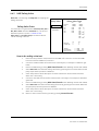
5
Set/Test
32
6
Service Log
33
Field replaceable unit
1
2
Spare part
1
1.1
1.2
1.3
1.4
1.5
1.6
1.7
1
2
3
3
4
4
5
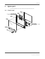
Front cover . . . . . . . . . . . . . . . . . . . . . . . . . . . . . . . . . . . . . . . . . . . . . . . . . . . . . . . . . . . . . . . . . . . . . . . . . . . .
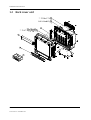
Back cover unit . . . . . . . . . . . . . . . . . . . . . . . . . . . . . . . . . . . . . . . . . . . . . . . . . . . . . . . . . . . . . . . . . . . . . . . .
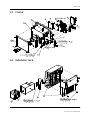
Frame. . . . . . . . . . . . . . . . . . . . . . . . . . . . . . . . . . . . . . . . . . . . . . . . . . . . . . . . . . . . . . . . . . . . . . . . . . . . . . . . .
Extension rack. . . . . . . . . . . . . . . . . . . . . . . . . . . . . . . . . . . . . . . . . . . . . . . . . . . . . . . . . . . . . . . . . . . . . . . . .
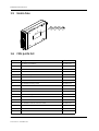
Hemo box . . . . . . . . . . . . . . . . . . . . . . . . . . . . . . . . . . . . . . . . . . . . . . . . . . . . . . . . . . . . . . . . . . . . . . . . . . . . .
FRU parts list . . . . . . . . . . . . . . . . . . . . . . . . . . . . . . . . . . . . . . . . . . . . . . . . . . . . . . . . . . . . . . . . . . . . . . . . . .
Other parts . . . . . . . . . . . . . . . . . . . . . . . . . . . . . . . . . . . . . . . . . . . . . . . . . . . . . . . . . . . . . . . . . . . . . . . . . . . .
Disassembly
2.1
2.2
2.3
2.4
2.5
2.6
2.7
6
Before disassembly. . . . . . . . . . . . . . . . . . . . . . . . . . . . . . . . . . . . . . . . . . . . . . . . . . . . . . . . . . . . . . . . . . . . 6
Tools needed . . . . . . . . . . . . . . . . . . . . . . . . . . . . . . . . . . . . . . . . . . . . . . . . . . . . . . . . . . . . . . . . . . . . . . . . . . 6
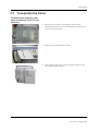
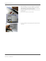
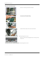
To separate the frame . . . . . . . . . . . . . . . . . . . . . . . . . . . . . . . . . . . . . . . . . . . . . . . . . . . . . . . . . . . . . . . . . 7
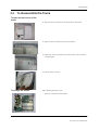
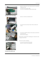
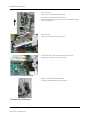
To disassemble the frame. . . . . . . . . . . . . . . . . . . . . . . . . . . . . . . . . . . . . . . . . . . . . . . . . . . . . . . . . . . . . . 9
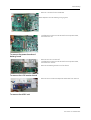
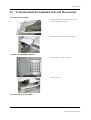
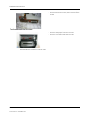
To disassemble the extended rack and the recorder. . . . . . . . . . . . . . . . . . . . . . . . . . . . . . . . . . . . 15
Handling and storage of LCD display component . . . . . . . . . . . . . . . . . . . . . . . . . . . . . . . . . . . . . . 17
Batteries . . . . . . . . . . . . . . . . . . . . . . . . . . . . . . . . . . . . . . . . . . . . . . . . . . . . . . . . . . . . . . . . . . . . . . . . . . . . . 18
2.7.1 Battery indicators. . . . . . . . . . . . . . . . . . . . . . . . . . . . . . . . . . . . . . . . . . . . . . . . . . . . . . . . . . . . . . 18
iv
Document no. 2050802-001
2.8
2.9
7
19
19
20
20
Technical specification
1
General Specifications
1.1
1.2
2
8
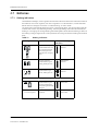
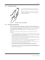
2.7.2 To check the battery . . . . . . . . . . . . . . . . . . . . . . . . . . . . . . . . . . . . . . . . . . . . . . . . . . . . . . . . . . .
2.7.3 Conditioning the batteries . . . . . . . . . . . . . . . . . . . . . . . . . . . . . . . . . . . . . . . . . . . . . . . . . . . . . .
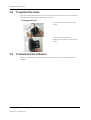
To replace the fuses . . . . . . . . . . . . . . . . . . . . . . . . . . . . . . . . . . . . . . . . . . . . . . . . . . . . . . . . . . . . . . . . . .
To download the software . . . . . . . . . . . . . . . . . . . . . . . . . . . . . . . . . . . . . . . . . . . . . . . . . . . . . . . . . . . .
1
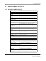
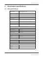
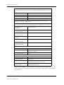
Genenral specifications . . . . . . . . . . . . . . . . . . . . . . . . . . . . . . . . . . . . . . . . . . . . . . . . . . . . . . . . . . . . . . . . 1
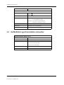
Defibrillator synchronization connector. . . . . . . . . . . . . . . . . . . . . . . . . . . . . . . . . . . . . . . . . . . . . . . . . 2
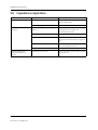
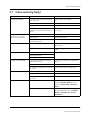
Parameters specifications
3
2.1
2.2
2.3
2.4
2.5
2.6
2.7
2.8
2.9
3
5
5
6
6
7
8
8
9
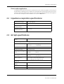
ECG specifications . . . . . . . . . . . . . . . . . . . . . . . . . . . . . . . . . . . . . . . . . . . . . . . . . . . . . . . . . . . . . . . . . . . . .
Impedance respiration specifications. . . . . . . . . . . . . . . . . . . . . . . . . . . . . . . . . . . . . . . . . . . . . . . . . . .
GE SpO2 specifications . . . . . . . . . . . . . . . . . . . . . . . . . . . . . . . . . . . . . . . . . . . . . . . . . . . . . . . . . . . . . . . . .
Nellcor SpO2 specifications . . . . . . . . . . . . . . . . . . . . . . . . . . . . . . . . . . . . . . . . . . . . . . . . . . . . . . . . . . . . .
Masimo SpO2 specifications . . . . . . . . . . . . . . . . . . . . . . . . . . . . . . . . . . . . . . . . . . . . . . . . . . . . . . . . . . . .
NIBP . . . . . . . . . . . . . . . . . . . . . . . . . . . . . . . . . . . . . . . . . . . . . . . . . . . . . . . . . . . . . . . . . . . . . . . . . . . . . . . . . .
Invasive blood pressure . . . . . . . . . . . . . . . . . . . . . . . . . . . . . . . . . . . . . . . . . . . . . . . . . . . . . . . . . . . . . . . .
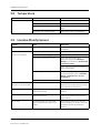
Temperature . . . . . . . . . . . . . . . . . . . . . . . . . . . . . . . . . . . . . . . . . . . . . . . . . . . . . . . . . . . . . . . . . . . . . . . . . .
Airway gases. . . . . . . . . . . . . . . . . . . . . . . . . . . . . . . . . . . . . . . . . . . . . . . . . . . . . . . . . . . . . . . . . . . . . . . . . .
E-MiniC Module
1
2
Introduction
1
Specifications
2
2.1
2
2
2
2
2
2
3
4
4
2.2
2.3
3
Functional description
3.1
3.2
3.3
4
General specifications . . . . . . . . . . . . . . . . . . . . . . . . . . . . . . . . . . . . . . . . . . . . . . . . . . . . . . . . . . . . . . . . .
2.1.1 Environmental specifications . . . . . . . . . . . . . . . . . . . . . . . . . . . . . . . . . . . . . . . . . . . . . . . . . . . .
2.1.2 Functional alarms. . . . . . . . . . . . . . . . . . . . . . . . . . . . . . . . . . . . . . . . . . . . . . . . . . . . . . . . . . . . . . .
CO2 measurement. . . . . . . . . . . . . . . . . . . . . . . . . . . . . . . . . . . . . . . . . . . . . . . . . . . . . . . . . . . . . . . . . . . . .
2.2.1 Typical performance . . . . . . . . . . . . . . . . . . . . . . . . . . . . . . . . . . . . . . . . . . . . . . . . . . . . . . . . . . . .
2.2.2 Technical specifications . . . . . . . . . . . . . . . . . . . . . . . . . . . . . . . . . . . . . . . . . . . . . . . . . . . . . . . . .
2.2.3 Normal conditions . . . . . . . . . . . . . . . . . . . . . . . . . . . . . . . . . . . . . . . . . . . . . . . . . . . . . . . . . . . . . .
2.2.4 Conditions exceeding normal. . . . . . . . . . . . . . . . . . . . . . . . . . . . . . . . . . . . . . . . . . . . . . . . . . . .
Respiration Rate (RR). . . . . . . . . . . . . . . . . . . . . . . . . . . . . . . . . . . . . . . . . . . . . . . . . . . . . . . . . . . . . . . . . . .
5
Measurement principle . . . . . . . . . . . . . . . . . . . . . . . . . . . . . . . . . . . . . . . . . . . . . . . . . . . . . . . . . . . . . . . . 5
3.1.1 CO2 measurement . . . . . . . . . . . . . . . . . . . . . . . . . . . . . . . . . . . . . . . . . . . . . . . . . . . . . . . . . . . . . . 5
Main components . . . . . . . . . . . . . . . . . . . . . . . . . . . . . . . . . . . . . . . . . . . . . . . . . . . . . . . . . . . . . . . . . . . . . 5
3.2.1 Gas sampling system . . . . . . . . . . . . . . . . . . . . . . . . . . . . . . . . . . . . . . . . . . . . . . . . . . . . . . . . . . . 6
3.2.2 MiniC sensor . . . . . . . . . . . . . . . . . . . . . . . . . . . . . . . . . . . . . . . . . . . . . . . . . . . . . . . . . . . . . . . . . . . . 8
3.2.3 CPU board . . . . . . . . . . . . . . . . . . . . . . . . . . . . . . . . . . . . . . . . . . . . . . . . . . . . . . . . . . . . . . . . . . . . . . 9
Connectors and signals . . . . . . . . . . . . . . . . . . . . . . . . . . . . . . . . . . . . . . . . . . . . . . . . . . . . . . . . . . . . . . . 10
Maintenance and checkout
11
4.1
12
12
12
13
4.2
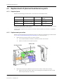
Replacement of planned maintenance parts . . . . . . . . . . . . . . . . . . . . . . . . . . . . . . . . . . . . . . . . . . .
4.1.1 Required parts . . . . . . . . . . . . . . . . . . . . . . . . . . . . . . . . . . . . . . . . . . . . . . . . . . . . . . . . . . . . . . . . .
4.1.2 Replacement procedure . . . . . . . . . . . . . . . . . . . . . . . . . . . . . . . . . . . . . . . . . . . . . . . . . . . . . . . .
Visual inspections . . . . . . . . . . . . . . . . . . . . . . . . . . . . . . . . . . . . . . . . . . . . . . . . . . . . . . . . . . . . . . . . . . . .
v
Document no. 2050802-001
B40/B20 Patient Monitor
4.3
5
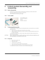
E-MiniC module disassembly and reassembly
5.1
5.2
6
Functional checkout . . . . . . . . . . . . . . . . . . . . . . . . . . . . . . . . . . . . . . . . . . . . . . . . . . . . . . . . . . . . . . . . . . 13
17
5.0.1 Before disassembly . . . . . . . . . . . . . . . . . . . . . . . . . . . . . . . . . . . . . . . . . . . . . . . . . . . . . . . . . . . .
5.0.2 Tools needed . . . . . . . . . . . . . . . . . . . . . . . . . . . . . . . . . . . . . . . . . . . . . . . . . . . . . . . . . . . . . . . . . .
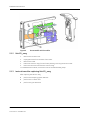
To disassemble the module . . . . . . . . . . . . . . . . . . . . . . . . . . . . . . . . . . . . . . . . . . . . . . . . . . . . . . . . . . .
5.1.1 Pump unit . . . . . . . . . . . . . . . . . . . . . . . . . . . . . . . . . . . . . . . . . . . . . . . . . . . . . . . . . . . . . . . . . . . . .
5.1.2 MiniCO2 assy . . . . . . . . . . . . . . . . . . . . . . . . . . . . . . . . . . . . . . . . . . . . . . . . . . . . . . . . . . . . . . . . . .
5.1.3 Instructions after replacing MiniCO2 assy . . . . . . . . . . . . . . . . . . . . . . . . . . . . . . . . . . . . . . .
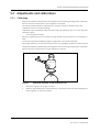
Adjustments and calibrations . . . . . . . . . . . . . . . . . . . . . . . . . . . . . . . . . . . . . . . . . . . . . . . . . . . . . . . . .
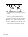
5.2.1 Calibrating. . . . . . . . . . . . . . . . . . . . . . . . . . . . . . . . . . . . . . . . . . . . . . . . . . . . . . . . . . . . . . . . . . . . .
5.2.2 Gas sampling system adjustment . . . . . . . . . . . . . . . . . . . . . . . . . . . . . . . . . . . . . . . . . . . . . . .
5.2.3 Flow rate measurement . . . . . . . . . . . . . . . . . . . . . . . . . . . . . . . . . . . . . . . . . . . . . . . . . . . . . . . .
5.2.4 Flow rate adjustment . . . . . . . . . . . . . . . . . . . . . . . . . . . . . . . . . . . . . . . . . . . . . . . . . . . . . . . . . .
5.2.5 Gas calibration . . . . . . . . . . . . . . . . . . . . . . . . . . . . . . . . . . . . . . . . . . . . . . . . . . . . . . . . . . . . . . . . .
17
17
17
17
18
18
19
19
21
21
21
22
Troubleshooting
23
6.1
23
24
24
25
25
25
6.2
6.3
6.4
Appendix A:
1.1
1.2
1.3
1.4
1.5
1.6
1.7
1.8
1.9
1.10
1.11
1.12
1.13
1.14
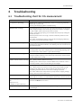
Troubleshooting chart for CO2 measurement . . . . . . . . . . . . . . . . . . . . . . . . . . . . . . . . . . . . . . . . . .
6.1.1 CO2 measurement . . . . . . . . . . . . . . . . . . . . . . . . . . . . . . . . . . . . . . . . . . . . . . . . . . . . . . . . . . . . .
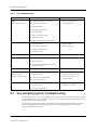
Gas sampling system troubleshooting . . . . . . . . . . . . . . . . . . . . . . . . . . . . . . . . . . . . . . . . . . . . . . . . .
6.2.1 Sampling system leak test. . . . . . . . . . . . . . . . . . . . . . . . . . . . . . . . . . . . . . . . . . . . . . . . . . . . . .
MiniC unit troubleshooting . . . . . . . . . . . . . . . . . . . . . . . . . . . . . . . . . . . . . . . . . . . . . . . . . . . . . . . . . . . .
Error messages. . . . . . . . . . . . . . . . . . . . . . . . . . . . . . . . . . . . . . . . . . . . . . . . . . . . . . . . . . . . . . . . . . . . . . .
Software download instruction
A-1
Overview. . . . . . . . . . . . . . . . . . . . . . . . . . . . . . . . . . . . . . . . . . . . . . . . . . . . . . . . . . . . . . . . . . . . . . . . . . . . . .
Contents of the upgrade kit . . . . . . . . . . . . . . . . . . . . . . . . . . . . . . . . . . . . . . . . . . . . . . . . . . . . . . . . . . . .
Related documents . . . . . . . . . . . . . . . . . . . . . . . . . . . . . . . . . . . . . . . . . . . . . . . . . . . . . . . . . . . . . . . . . . . .
Connection methods . . . . . . . . . . . . . . . . . . . . . . . . . . . . . . . . . . . . . . . . . . . . . . . . . . . . . . . . . . . . . . . . . .
Required equipment . . . . . . . . . . . . . . . . . . . . . . . . . . . . . . . . . . . . . . . . . . . . . . . . . . . . . . . . . . . . . . . . . . .
Workflow. . . . . . . . . . . . . . . . . . . . . . . . . . . . . . . . . . . . . . . . . . . . . . . . . . . . . . . . . . . . . . . . . . . . . . . . . . . . . .
Prepare the connections . . . . . . . . . . . . . . . . . . . . . . . . . . . . . . . . . . . . . . . . . . . . . . . . . . . . . . . . . . . . . . .
Prepare the patient monitor(s) . . . . . . . . . . . . . . . . . . . . . . . . . . . . . . . . . . . . . . . . . . . . . . . . . . . . . . . . . .
Prepare the service PC . . . . . . . . . . . . . . . . . . . . . . . . . . . . . . . . . . . . . . . . . . . . . . . . . . . . . . . . . . . . . . . . .
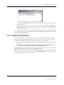
Start the Software Transfer Utility . . . . . . . . . . . . . . . . . . . . . . . . . . . . . . . . . . . . . . . . . . . . . . . . . . . . . .
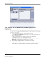
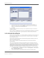
Specify the IP address(es) of the target patient Monitor(s) . . . . . . . . . . . . . . . . . . . . . . . . . . . . . . . .
Transfer the software . . . . . . . . . . . . . . . . . . . . . . . . . . . . . . . . . . . . . . . . . . . . . . . . . . . . . . . . . . . . . . . . . .
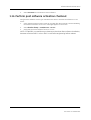
Activate the software . . . . . . . . . . . . . . . . . . . . . . . . . . . . . . . . . . . . . . . . . . . . . . . . . . . . . . . . . . . . . . . . . .
Perform post software activation checkout . . . . . . . . . . . . . . . . . . . . . . . . . . . . . . . . . . . . . . . . . . . . .
1
1
1
1
2
2
2
3
4
5
6
7
8
9
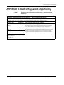
Appendix B:
ElectroMagnetic Compatibility
B-1
Appendix C:
Installation and checkout form, B40/B20
C-1
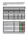
Appendix D:
Maintenance and checkout form, B40/B20
D-1
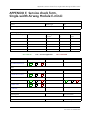
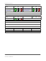
Appendix E:
Service check form, Single-width Airway Module E-miniC
E-1
vi
Document no. 2050802-001
1 Introduction
About this manual
Intended purpose of this device (Indications for use)
This device is a portable multiparameter unit to be used for monitoring and recording of, and to
generate alarms for, multiple physiological parameters of adult, pediatric, and neonatal
patients in a hospital environment and during intra-hospital transport. The B40/B20 Patient
Monitor is intended for use under the direct supervision of a licensed health care practitioner.
The PROCARE Monitor B40/B20 is not intended for use during MRI.
The PROCARE Monitor B40/B20 monitors and displays oscillometric non-invasive blood
pressure (systolic, diastolic and mean arterial pressure), invasive blood pressure, end-tidal
carbon dioxide, heart/pulse rate, respiration rate, ECG (including arrhythmia and ST segment
analysis), temperature with a reusable or disposable electronic thermometer for continual
monitoring
Esophageal/Nasopharyngeal/Tympanic/Rectal/Bladder/Axillary/Skin/Airway/Room/Myocardi
al/Core/Surface temperature, and functional oxygen saturation (SpO2) and pulse rate via
continuous monitoring, including monitoring during conditions of clinical patient motion or low
perfusion.
Intended audience
This Technical reference manual is meant for service representatives and technical personnel
who install, configure, maintain, administer, troubleshoot or repair B40/B20 monitor running
the software license VSP-A.
Notes to the reader
As the monitor setup may vary, some functions described may not be available in the monitor
you are using.
•
•
The order code for the manual is 2050802-001.
Read the manual through and make sure that you understand the procedures described
before the installation of the monitor. To avoid risks concerning safety or health, strictly
observe the warning indications. If you need any assistance concerning the installation,
please do not hesitate to contact your authorized distributor.
Installation without network are allowed by customer. The network installation and service are
allowed by authorized service personnel only.
GE Healthcare assumes no responsibility for the use or reliability of its software in equipment
that is not furnished by GE.
Responsibility of the manufacturer
GE Medical Systems Information Technologies, Inc. (GE) is responsible for the effects on safety,
reliability and performance of the equipment only if:
Assembly operations, extensions, readjustments, modifications, or repairs are carried out
by persons authorized by GE.
The electrical installation of the relevant room complies with the requirements of the
appropriate regulations.
The equipment is used in accordance with the “User's Guide.”
1-1
Document no. 2050802-001
B40/B20 Patient Monitor
The equipment is installed, maintained and serviced in accordance with this manual.
Product availability
Some of the product parts and accessories mentioned in this manual may not be available in
all countries.
Please, consult your local representative for the availability.
Related documentation
Clinical aspects, basic methods of measurement and technical background: PROCARE
Monitor B40/B20 User’s Reference Manual
Options and selections of the software: PROCARE Monitor B40/B20 Default Configuration
Worksheet
Compatible supplies and accessories: PROCARE Monitor B40/B20 Supplies and
Accessories
Other devices closely related to the monitor:
•
•
iCentral and iCentral Client User's Reference Manual
CIC Pro Clinical Information Center Operator's Manual
Conventions used
To help you find and interpret information easily, the manual uses consistent text formats:
Sign the check form after performing the procedure.
Within this manual, special styles and formats are used to distinguish between terms viewed
on screen, a button you must press, or a list of menu commands you must select:
Names of hardware keys on the keypad are written in bold typeface: NIBP
Start/Cancel.
Menu items are written in bold italic typeface: Monitor Setup.
Emphasized text is in italic typeface.
When referring to different sections in this manual, section names are enclosed in double
quotes: “Cleaning and care”.
The word “select” means choosing and confirming.
Messages (alarm messages, informative messages) displayed on the screen are written
inside single quotes: 'Learning.'
Note statements provide application tips or other useful information.
Illustrations and names
All illustrations in this manual are only examples, and may not necessarily reflect your system
settings or data displayed in your system. If a particular selection is not available in your
system, the selection is shown grayed.
1-2
Document no. 2050802-001
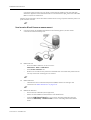
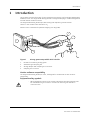
1
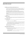
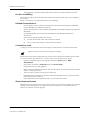
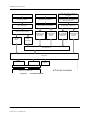
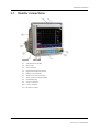
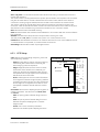
Overview
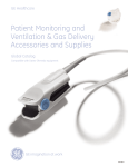
The B40/B20 is a modular multiparameter patient monitor. The monitor is especially designed
for monitoring in intensive care units. It can also be used during transportation within the
hospital.
The modular design makes the system flexible and easy to upgrade.
NOTE: Your system may not include all these components. Consult your local representative
for the available components.
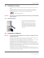
Figure 1
B40/B20 monitor with hemo and extension rack modules
1-3
Document no. 2050802-001
B40/B20 Patient Monitor
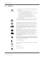
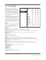
1.1 Symbols
-
On the rear panel this symbol indicates the following warnings
and cautions:
-
Electric shock hazard. Do not open the cover or the back.
Refer servicing to qualified personnel.
-
For continued protection against fire hazard, replace the fuse
only with one of the same type and rating.
-
Disconnect from the power supply before servicing.
-
Do not touch the monitor during defibrillation.
-
Do not use the monitor without manufacturer approved
mounting attached.
Electrostatic sensitive device. Connections should not be made to
this device unless ESD precautionary procedures are followed.
Type BF (IEC 60601-1) protection against electric shock. Isolated
(floating) applied part suitable for intentional external and internal
application to the patient, excluding direct cardiac application.
Type BF (IEC 60601-1) defibrillator-proof protection against electric
shock. Isolated (floating) applied part suitable for intentional
external and internal application to the patient, excluding direct
cardiac application.
Type CF (IEC 60601-1) protection against electric shock. Isolated
(floating) applied part suitable for intentional external and internal
application to the patient, including direct cardiac application.
Type CF (IEC 60601-1) defibrillator-proof protection against electric
shock. Isolated (floating) applied part suitable for intentional
external and internal application to the patient including direct
cardiac application.
When displayed in the upper left corner of the screen, indicates that
the audio OFF. When displayed in the menu or digit fields, indicates
that the alarm source has been turned off or alarm does not meet
the alarm-specific activation criteria.
In the front panel: battery
Equipotentiality. Monitor can be connected to potential equalization
conductor.
Alternating current
Bell cancel. Audio pause.
1-4
Document no. 2050802-001
Home. Return to the main display.
Standby or power indicator.
Fuse. Replace the fuse only with one of the same type and rating
Gas inlet.
Gas outlet.
IP21
SN,S/N
Degree of ingress protection.
Serial number
Date of manufacture. This symbol indicates the date of
manufacture of this device. The four digits identify the year.
Maunfacturer: This symbol indicates the name and the address of
the manufacturer.
European authorized representative.
European Union Declaration of Conformity.
Rx Only U.S.
Prescriptive Device. USA only. For use by or on the order of a
Physician or persons licensed by state law.
Fragile. Handle with care.
Keep dry. Protect from rain.
This way up.
Storage temperature
This symbol depicts the transportation and storage atmospheric
pressure range of 700 to 1060 hPa
1-5
Document no. 2050802-001
B40/B20 Patient Monitor
Recycled materials or may be recycled.
This symbol indicates that the waste of electrical and electronic
equipment must not be disposed as unsorted municipal waste and
must be collected separately. Please, contact an authorized
representative of the manufacturer for information concerning the
decommissioning of your equipment.
The separate collection symbol is affixed to a battery, or its
packaging, to advise you that the battery must be recycled or
disposed of in accordance with local or country laws. To minimize
potential effects on the environment and human health, it is
important that all marked batteries that you remove from the
product are properly recycled or disposed. For information on how
the battery may be safely removed from the device, please consult
the service manual or equipment instructions. Information on the
potential effects on the environment and human health of the
substances used in batteries is available at this url:
http://www.gehealthcare.com/euen/weee-recycling/index.html
This product consists of devices that may contain mercury, which
must be recycled or disposed of in accordance with local, state, or
country laws. (Within this system, the backlight lamps in the
monitor display contain mercury.)
A
B
B
Battery operation and remaining capacity. The height of the green
bar indicates the charging level.
Battery (A) charging (white bar)
Battery (A) failure
B
Both batteries failed
Battery (A) missing
Submenu. Selecting a menu item with this symbol opens a new
menu.
1-6
Document no. 2050802-001
The monitor is connected to Network.
A blinking heart next to the heart rate or pulse rate value indicates
the beats detected.
A lung next to the respiration rate value indicates that respiration
rate is calculated from the impedance respiration measurement.
1-7
Document no. 2050802-001
B40/B20 Patient Monitor
1.2 Safety information
1.2.1 General
This device is intended for use under the direct supervision of a licensed health care
practitioner.
Contact GE for information before connecting any devices to the equipment that are not
recommended in this manual.
Parts and accessories used must meet the requirements of the applicable IEC 60601 series
safety standards, and/or the system configuration must meet the requirements of the IEC
60601-1-1 medical electrical systems standard.
Periodically, and whenever the integrity of the device is in doubt, test all functions.
The use of ACCESSORY equipment not complying with the equivalent safety requirements of
this equipment may lead to a reduced level of safety of the resulting system. Consideration
relating to the choice shall include:
•
•
use of the accessory in the PATIENT VICINITY; and
evidence that the safety certification of the ACCESSORY has been performed in
accordance to the appropriate IEC 60601-1 and/or IEC 60601-1-1 harmonized
national standard.
If the installation of the equipment, in the USA, will use 240V rather than 120V, the source must
be a center-tapped, 240V, single-phase circuit.
1.2.2 Safety message signal words
Safety message signal words designate the severity of a potential hazard.
DANGER: Indicates a hazardous situation that, if not avoided, will result in death or
serious injury. No danger messages apply to this system.
WARNING: Indicates a hazardous situation that, if not avoided, could result in death or
serious injury.
CAUTION: Indicates a hazardous situation that, if not avoided, could result in minor or
moderate injury.
NOTE: Indicates a hazardous situation not related to personal injury that, if not
avoided, could result in property damage.
1.2.3 Safety precautions
The following list contains general warnings and cautions you should know before installing,
maintaining or servicing the system. Warnings and cautions specific to the use of the system
can be found in the User’s Guide and User’s Reference Manual.
Warnings
• Use only GE recommended power cords
• When disconnecting the system from the power line, remove the plug from the wall outlet
first
•
•
Due to high voltage, use insulated screw driver
High voltage on test body; do not touch it during the test
1-8
Document no. 2050802-001
•
To avoid the risk of electric shock, this equipment must only be connected to a supply
mains with protective earth.
•
•
•
•
Always check that power cord and plug are intact and undamaged
All system devices must be connected to the same power supply circuit
Only interconnect devices when determined safe by qualified biomedical personnel
Only devices that are specified compliant with IEC 60950-1 or IEC 60601-1 may be
connected to the Ethernet MC or IX ports
•
•
•
•
Biomed must determine interconnected parts are safe.
•
•
Verify compatibility of all system components prior to installation
•
•
•
Regular preventive maintenance should be carried out annually.
•
•
•
Do not use without manufacturer approved mounting
If the software package is changed, all clinical settings will reset to factory defaults.
Do not use with iCentral software V5.0.2 and earlier or Mobile Care Server software earlier
of V5.2.
Use only approved accessories, including mounts, and defibrillator-proof cables and
invasive pressure transducers. For a list of approved accessories, see the supplies and
accessories list delivered with the monitor. Other cables, transducers and accessories
may cause a safety hazard, damage the equipment or system, result in increased
emissions or decreased immunity of the equipment or system or interfere with the
measurement.
Do not use multiple modules with identical measurements in the same monitor.
The user may only perform maintenance procedures specifically described in this
manual.
Incorrect power line frequency setting could adversely affect ECG processing.
Make sure patient is not being monitored while servicing the equipment.
Don’t press power key when changing language or doing factory reset.
Cautions
• Set the time of a newly added network device as close as possible to the time of devices
already on the network
1.2.4 ESD precautionary procedures
•
To avoid electrostatic charges building up, it is recommended to store, maintain and use
the equipment at a relative humidity of 30% or greater. Floors should be covered by ESD
dissipative carpets or similar. Non-synthetic clothing should be used when working with
the component.
•
To prevent applying a possible electrostatic discharge to the ESD sensitive parts of the
equipment, one should touch the metallic frame of the component or a large metal object
located close to the equipment. When working with the equipment and specifically when
the ESD sensitive parts of the equipment may be touched, a grounded wrist strap
intended for use with ESD sensitive equipment should be worn. Refer to the
documentation provided with the wrist straps for details of proper use.
1-9
Document no. 2050802-001
B40/B20 Patient Monitor
ESD precautionary procedure training
It is recommended that all potential users receive an explanation of the ESD warning symbol
and training in ESD precautionary procedures.
The minimum contents of an ESD precautionary procedure training should include an
introduction to the physics of electrostatic charge, the voltage levels that can occur in normal
practice and the damage that can be done to electronic components if they are touched by an
operator who is electrostatically charged. Further, an explanation should be given of methods
to prevent build-up of electrostatic charge and how and why to discharge one’s body to earth
or to the frame of the equipment or bond oneself by means of a wrist strap to the equipment or
the earth prior to making a connection.
1.2.5 Disposal
Dispose of the whole device, parts of it and its packing material and manuals in accordance
with local environmental and waste disposal regulations.
1.3 Service information
1.3.1 Service requirements
Follow the service requirements listed below.
•
•
•
Refer equipment servicing to GE authorized service personnel only.
•
Failure on the part of the responsible individual, hospital, or institution using this
equipment to implement a satisfactory maintenance schedule may cause undue
equipment failure and possible health hazards.
•
Regular maintenance, irrespective of usage, is essential to ensure that the equipment will
always be functional when required.
Any unauthorized attempt to repair equipment under warranty voids that warranty.
It is the user's responsibility to report the need for service to GE or to one of their
authorized agents.
1.3.2 Equipment identification
Every GE device has a unique serial number for identification. The device plate is located on the
rear of the patient monitor.
Serial number for B40: SN: SG2XXXXXXXXWA
Serial number for B20: SN: SGFXXXXXXXXWA
1-10
Document no. 2050802-001
System description
2
System description
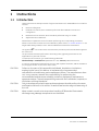
2.1 Introduction
The B40/B20 monitor build up a freely configurable modular system. The architecture is
designed to enable different module combinations so that the user is able to get the desirable
parameter and feature set. This modular approach makes it possible to add new features
when they are needed.
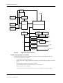
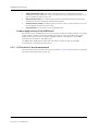
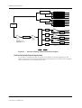
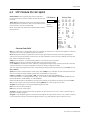
2.2 Bus structure
The operation of monitor is based on two communication channels, the CPU bus and module
bus. All units, including the modules, receive power from the same power supply, which is an
integral part of the monitor frame.
NAND
Flash
Ethernet
DATA BUS
SDRAM
AT91 ARM
USB HOSE
AT91SA
M7s256
IIC BUS
Sound
RS485
Address bus
LCD
Figure 2
LCD DATA BUS
General bus structure of monitor
The CPU bus is a communication channel used only for internal data transfer. It is based on the
AT91 ARM local bus. Data and address are transferred on this 32 bit wide bus using the CPU
clock frequency.
The module bus is for the parameter modules. The bus is based on the industry standard
RS-485, which uses a differential serial method to transfer data. The module bus uses a 500
kbps data transfer rate.
1-11
Document no. 2050802-001
B40/B20 Patient Monitor
The RS-485 type of serial communication supports so-called multidrop or party line
connections. This means that all parameter modules connected to the module bus use exactly
the same lines for communication. The advantage of this is that all bus connectors are
identical and the modules can be connected in any order and position.
2.3 Distributed processing
This is a multiprocessor system. All parameter modules have their own microprocessor, which
performs functions such as waveform filtering, parameter related computing and pneumatic
control, etc. At the same time the main CPU performs higher level tasks such as trending and
alarm control. While the parameter modules and CPU are performing their tasks, the UPI
(Universal Peripheral Interface) microprocessor handles all functions needed to transfer data
between the parameter modules and the CPU.
This kind of parallel processing gives one major advantage to centralized processing. When
new parameter modules are added to the system, the processing power is increased. As a
result, the system does not slow down when new features are added.
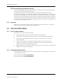
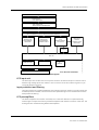
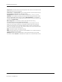
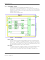
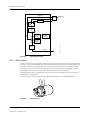
2.4 Module communication
The communication master controlling data transfers between the CPU and parameter
modules is called UPI processor. It sends data to each connected module 100 times a second.
Modules respond to each data request immediately by sending a data package, whose length
depends on the type of the module. This communication protocol ensures that each module
receives and sends data every 10 ms. If a module does not respond to data requests, the UPI
processor presumes that the module is disconnected.
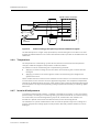
The data transfered on USB bus between main CPU and UPI processor.
Marker Out
Main CPU
Figure 3
USB BUS
UPI Processor
Module BUS
Principle of UPI section operation
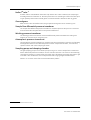
2.5 Software loading
The program memory on the CPU board is loaded with monitor software and selected
language files at the factory. The software is used for running all the functions that are
integrated into the CPU board. For service upgrade main software and language files, please
refer to "Software download instruction" in Appendix A or the “B40/B20 Patient Monitor
Software download instruction”.
1-12
Document no. 2050802-001
System description
How to do cold start?
The patient monitor performs a cold start, if there is over 15 minutes from the previous power
off. You can perform a cold start by 2 methods:
•
Press ON/Standby button to turn off the monitor, waiting for 15 minutes to turn on the
monitor. Or,
•
Press ON/Standby button for a long time (about 15 seconds until the words “monitor is
shutting downing...“ disappear) to turn off the monitor. Then turn on the monitor.
NOTE: All the patient data and monitor settings will be lost after cold start.
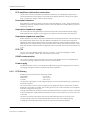
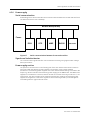
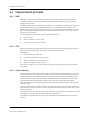
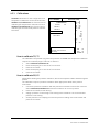
2.6 Parameter modules
PATIENT
A/D
convert
Peripheral
drivers
Figure 4
CPU
RAM
EEPROM
Opto isolation
+13...16V
VMOD
Data
MODULE BUS
Analog
electronics
Isolation
transformer
Patient isolation
+5V
RS485
drivers
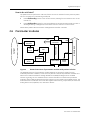
General structure of parameter modules with patient isolation
The detailed structure of a parameter module depends on the specific needs for each
individual parameter. However, some common parts are used in the parameter modules. The
electronics inside the module is usually divided into isolated (floating) and non-isolated
sections. Typically, the non-isolated section consists of buffers to interface the parameter
module to the module bus while the rest of the electronics is located in the isolated section. The
isolated section includes the microcontroller together with memory components, the front-end
analog electronics (amplifiers, etc.) and sensor drivers.
1-13
Document no. 2050802-001
B40/B20 Patient Monitor
3
Frame functional description
3.1 Main components
3.1.1 Keyboards
User interface parts
The Horizontal Membrane keypad containing 17 keys. The keypads are foil membrane
keypads. The keypads are connected to the UPI section of the CPU board.
Trim Knob is used for menu selection.
3.1.2 Display
The B40 use 12.1” LCD display with SVGA 800 x 600 resolution has bright long life lamps and a
wide viewing angle.
The B20 use 10.4” LCD display with SVGA 800 x 600 resolution has bright long live lamps and a
wide viewing angle.
NOTE: The LCD display backlight circuit runs on a high voltage. Do not touch the inverter board
or the backlight tube leads when powered.
Backlights
The backlight lamp unit consists of two integrated cold cathode fluorescent lamps. The
backlight lamp unit is driven by a separate inverter board.
1-14
Document no. 2050802-001
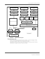
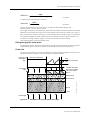
Frame functional description
I/O connector
AC INLET
100-240 Vac
50/60 Hz
Cable or wires
Pin-to-pin connection
Alarm light board
Speaker
AC/DC
Unit
LCD
display
SVGA
Nurse call
CPU
Board
Serial data
Power Board
XY/CW
Backlight
inverter
CCFL
LAMPS
Module bus
Module bus
Module
interface board
Network
Vmod
BAT2
SMBUS
BAT1
SMBUS
User interface
board
External interface
board
Network
Smart
battery B
Li-ion
9-12.6V
Module bus
connector
CW
Battery board
Smart
battery A
Li-ion
9-12.6V
Module bus
connector
XY
Trim Knob
Keyboard/Memb
rane switch
Power
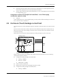
indicator
Multi I/O
Multi I/O
adaptor
Nurse DFB Serial
call MK out port
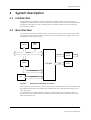
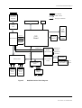
Figure 5
B40/B20 Monitor block diagram
1-15
Document no. 2050802-001
B40/B20 Patient Monitor
3.1.3 CPU board
The board is based on AT91 ARM microprocessor. Other functions include LVDS display driver,
10/100Mbps on board Ethernet, Alarm Light function, KEY board and rotor encoder control,
audio driver function, nurse call function, defibrillation function, module bus function.
The CPU section takes care of the central processing.
The main features are:
•
•
•
•
•
•
AT91 ARM
266 MHz Main CPU clock
64MBytes SDRAM
4 MBytes minimum NAND flash memory
8 MBytes Data flash memory
Main CPU Provides one standard UART communication
Connectors
Ethernet communication connector
Color LCD operation connector
Audio operation connector
Alarm Light indicator operation connector
Power board connection connector
Voltage supervision
There are two voltage supervision chips that control the system reset signals.
The +3.3V supervision chip outputs reset signals for +3.3V devices. 3.3V Reset Threshold will be
Falling: min 3.00 V; max 3.15 V.
The +1.2V supervision chip outputs reset signals for +1.2V devices. 1.2V Reset Threshold will be
Falling: min 1.08V; max 1.14 V.
1-16
Document no. 2050802-001
Frame functional description
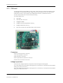
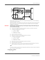
3.1.4
Power board
The Power board converts the output voltage of AC/DC unit and battery voltage to various
supply voltages for the electronics of monitor. The Power board provides monitor system
power function, module bus power function, LCD backlight power and power failure alarm.
Power board operation is controlled by PMC (Power Management Controller) CPU. PMC takes
care of power path controlling. Power Board incorporates the SMBus interface between the
PMC, battery charger IC, and smart battery.
Power board provides the system voltage for +3.3V, +5V. And Power Board provides 15V power
for measurement modules connected patient monitor module bus.
The Boost converter of PMC system provides module voltage supply for measurement
modules through patient monitor module bus.It operates at input voltage from 9V to15V.
Power Board create an power failure alarm for user to notice unexpected loss of power supply.
It indicate power failure alarm by blinking patient monitor yellow alarm light and buzzer alarm.
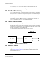
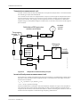
Block diagram of the power supplies is represented in following
1-17
Document no. 2050802-001
B40/B20 Patient Monitor
MUX
+5V_PMC
ACDC (15V)
Battery Charger
Battery 1
Power Path
Power Management Controller (PMC)
VSYS Enable
Switch
Over Voltage
Protection
(Crowbar)
Battery 2
VSYS
+3.3V
3.3V & 5V Buck
Regulator
15V Boost
Regulator
+5V
Over Current
Protection & Current
Sense
+5V_PMC Linear
Regulator
LCD Backlight
Enable Switch
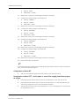
Figure 6
Power Fail Alarm
VMOD
+5V_PMC
Backlight_VCC
Power board block diagram
Power management controller
The power management controller (PMC) used is the Freescale MC9508AC60CFUE, 8 bit
microcontroller. The PMC is used to:
Control power supplies sequencing
Monitor the power supply voltages and currents via internal analog to digital converters
(ADCs)
Disabling power supplies during fault conditions
Communicate with the CPU board via UART communication
Read and write to a IIC EEPROM
Communicate with smart batteries and a level 2 smart battery charger via SMBus.
1-18
Document no. 2050802-001
Frame functional description
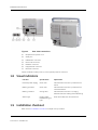
3.1.5 AC/DC unit
AC/DC unit
The AC/DC unit is a compact medical power supply based on high-efficiency technology. It is
designed for 65 watt continuous output power, universal AC input and 15V output voltage.
3.1.6 Batteries
The B40/B20 has two lithium-ion batteries, located in the battery compartment. The power
board connects one of the batteries to be the power source, if no power is received from the
AC/DC unit.The battery charging is controlled by the power board.
The batteries can be charged separately, and screen symbols and monitor frame LED
indicators indicate their charging level and possible failure.
NOTE: When the monitor is battery powered, the green battery LED is on. When the monitor is
mains powered, the green mains LED is on.
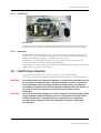
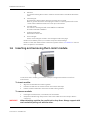
3.2 Interfacing computer
A computer is connected to the serial port connector on the Multi I/O adapter.
Contact your authorized GE Healthcare distributor for further advice on computer interface.
WARNING
WARNING
Connecting electrical equipment together or using the same extension cord
for more than one device may cause their leakage currents to exceed the
limits specified in relevant safety standards. Always make sure that the
combination complies with the international safety standard IEC 60601-1-1
for medical electrical systems and with the requirements of local
authorities.
Connecting the power supply cord of the computer to the wall power outlet
may cause the computer leakage current to exceed the limit specified for
medical equipment. A computer must be supplied from an additional
transformer providing at least basic isolation (isolating or separating
transformer).
1-19
Document no. 2050802-001
B40/B20 Patient Monitor
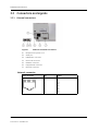
3.3 Connectors and signals
3.3.1 External connectors
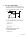
Figure 7
External connectors of Frame
(1)
Receptacle for power cord
(2)
Serial port
(3)
Defibrillator connector
(4)
Nurse call connector
(5)
Network connector
(6)
Equipotential connector
(7)
Multi I/O connector
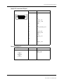
Network connector
RJ45 connector
1 2 3 4 5 6 7 8
1-20
Document no. 2050802-001
Pin
Signal
1
2
3
4
5
6
7
8
Tx +
Tx Rx +
N/C
N/C
Rx N/C
N/C
Frame functional description
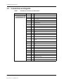
Multi I/O connector(26 pin)
26 pin female connector
18
26
10
19
Pin
Signal
1
2
3
4
5
6
7
8
9
10
11
12
13
14
15
16
17
18
19
20
21
22
23
24
25
GND
NC
NC
NC
NC
NC
SERIAL_TXD
SERIAL _CTS#
GND
GND
NC
NC
DEFIB_MARKER_OUT
NC
NC
26
GND
Pin
Signal
1
2
3
GND
Nurse_Call
Nurse_Call
SERIAL_RXD
SERIAL_RTS#
GND
GND
NURSE_CALL
NC
NC
NC
NC
SERIAL_+3V3
Nurse Call (pin 3)
Nurse call connector
1-21
Document no. 2050802-001
B40/B20 Patient Monitor
Serial port
9 pin female connector
5
1
9
6
Pin
Signal
1
2
3
4
5
6
7
8
9
GND
SERIAL_RXD
SERIAL_TXD
SERIAL+3.3V
GND
N/C
SERIAL_RTS
SERIAL_CTS
N/C
Pin
Signal
L
Live
PE
Protected earth
N
Neutral
Main power
Mains connector
Defib connector (Pin 7)
Female mini din7 connector Pin
1
2
3
4
5
6
7
1-22
Document no. 2050802-001
Signal
GND
GND
GND
GND
DEFIB_MARKER_OUT
NC
GND
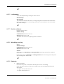
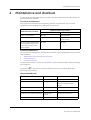
Hemo-dynamic module introduction
4
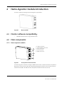
Hemo-dynamic module introduction
The hemo module provide general hemodynamic parameters.
Figure 8
Hemo module
4.1 Monitor software compatibility
B40/B20 Patient Monitor using software VSP-A
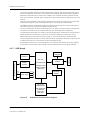
4.2 Main components
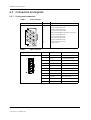
4.2.1 Hemo-dynamic module
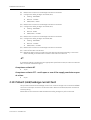
1
2
1.
2.
3.
4.
5.
InvBP connector
Temperature connector
SpO2 connector
ECG connector
NIBP connector
3
4
5
Figure 9
Front panel of hemo module
The Hemo-dynamic module including the NIBP measurement, 5-lead ECG with the Impedance
Respiration measurement, SpO2 with the plethysmographic waveform, two invasive pressure
measurements (IBP1 and IBP2) and two temperature measurements (T1 and T2).
1-23
Document no. 2050802-001
B40/B20 Patient Monitor
The monitor displays waveforms and measurement readings, and handles the trending and
alarm management. The ECG (e.g. heart beat and arrhythmia detection) and the Impedance
Respiration algorithms are in the monitor software. The modules measure signals and send
them to the monitor. The NIBP, SpO2, Temperature and Invasive Pressure algorithms are in the
module.
There are four parameter circuit boards inside the hemo-dynamic module for processing the
measurement signals. Each processing board has a microcontroller with software.
The NIBP parameter measurement requires one signal processing board, pneumatic system,
valve and pump unit connected to NIBP parameter board.
The second parameter board is the optional board, for Nellcor or Masimo SpO2 measurement,
it’s Masimo MS-2011 board or Covidien NELL1GE-S board at different configuration.
The third parameter board is for GE SpO2, IBP and Temperature measurement including input
board. All these three parameter is optional, according to different configuration, using
different board: it’s STP board, TP board for Nellcor, TP board for Masimo, GE SpO2 board.
The fourth parameter board is for 3/5-lead ECG with the Impedance Respiration measurement
including ECG input unit connected to the ECG parameter board.
All parameter boards are connected together via module bus flex board connecting voltage
and module communication, the module communicates with frame through RS-485 bus.
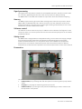
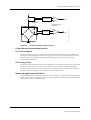
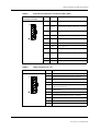
4.2.2 NIBP board
EEPROM
1024Bytes
Module bus connector
Main CPU
AT91SAM7S256
RS485
interface
Pneumatic
control
256KBytes Flash
64KBytes SRAM
10bits ADC
PWR_
SYN
Pressure
sensor
NIBP_+5V
6VD
Power supply
MAIN_REF
Safety CPU
MSP430F2013
2KB+256B Flash
128B RAM
16bits SigmaDelta ADC
Figure 10
1-24
Document no. 2050802-001
NIBP board functional block diagram
Pump
connector
Valves
connector
Hemo-dynamic module introduction
Signal processing
Two signals from the pressure transducers are amplified and sent to the A/D converter. After
the converter, digitized signals are sent to the microprocessor for data processing.
The NIBP board is controlled with an ARM7 microprocessor at 16 MHz oscillator frequency.
Memory
The NIBP program memory (processor flash memory) size is 256k x 8. The processor has 64
kBytes RAM. The EEPROM size is 8K x 8 and it is used to store the calibration values for the
pressure transducers, the pulse valve constants gained during measurements, the PC board
identification, and the module serial number.
Software control
The software controls valves and a pump. In addition to the individual on/off signals for each
component there is a common power switch for the valves and the pump that can be used at
pump/valve failures.
Safety circuit
The NIBP board is equipped with an independent safety circuit to disconnect supply voltages
from the pump and the valves if the cuff has been pressurized longer than the preset
maximum measurement time, or if the pressure of the cuff is inflated over the specified
pressure limit. The maximum measurement time values and pressure limits for different
measurement modes have been specified in the technical specification section of this manual.
Pneumatics
1
7
5, 6
3
2
4
1
The module has the following pneumatics parts:
1.
Intake air filter; for preventing dust and other parts from entering the air pump and the
valves.
2.
Air pump; for pumping the measuring pressure of the cuff.
3.
Deflation Valve; for producing a linear pressure fall (bleeding) in order to measure the
blood pressure of the patient.
1-25
Document no. 2050802-001
B40/B20 Patient Monitor
4.
Safety valve/Dump valve; The Safety valve/Dump valve is intended to be used for
deflating the cuff in single fault case, i.e. to prevent too long a measurement time or too
high an inflation pressure of the cuff.
5.
Main pressure sensor; for measuring the pressure of the blood pressure cuff and the
pressure fluctuations caused by arterial wall movement.
6.
Second pressure sensor; for detecting the, cuff loose, cuff occlusion situations, etc. and
for recognizing the pressure sensor fault.
7.
Cuff connector; for connection and hose identification.
Power supply section of the NIBP board
All connections are established via a 10-pin connector (male). The module needs a +15 V (dirty)
power supply to operate. The supply voltage Vmod 15V +/- 3% is generated in the power
supply section of the monitor. The other voltages needed for the operation of the NIBP
measurement are made on the NIBP board.
The NIBP power supply synchronizes the ECG and STP isolation power and supplies
non-isolated 5 V to the ECG and STP board.
4.2.3 ECG board in 5-lead measurement
The ECG measurement consists of the functions shown in Figure 11. All functions are located in
the ECG board except the ECG input unit.
1-26
Document no. 2050802-001
Hemo-dynamic module introduction
PATIENT AND ECG ELECTRODES
ECG CABLE
- ECG LEAD SET
- ECG TRUNK CABLE
ECG INPUT UNIT
- ECG CONNECTOR
- INPUT PROTECTION RESISTORS
INPUT PROTECTION DIODES FOR ECG & RESPIRATION MEASUREMENT
INPUT FILTERING FOR ECG & RESPIRATION MEASUREMENTS
RESPIRATION
MEASUREMENT
AMPLIFIERS
RESPIRATION
MEASUREMENT
CURRENT SUPPLY
ECG
PREAMPLIFIERS &
RLD CIRCUIT
LEADS OFF &
PACER &
DEFIBRILLATION
DETECTION
BASELINE
RESTORATION
RS 485
COMMUNICATION
POWER SUPPLY
ISOLATION
ISOLATION
NV
MEMORY
MODULE BUS CONNECTOR
Figure 11
ECG BLOCK DIAGRAM
12_lead_ECG_meas_blck_dgrm.vsd
ECG CPU
ECG measurement block diagram
ECG input unit
The ECG input unit consists of the front panel connector and the ECG input connector board
with the high voltage protection resistors. The connector for the ECG cable is a green 11-pin
rectangle shaped connector.
Input protection and filtering
The input protection is implemented with high voltage protection resistors in the ECG input unit
and with protection diodes in the ECG board. The input filtering for ECG measurement is done
with passive RC filtering.
ECG preamplifiers
The buffer amplifiers are used for each lead. The “Leads off” detection is implemented by
measuring the output level of the input buffer amplifiers with the A/D converter of the CPU. The
ECG signals are measured using differential amplifiers.
1-27
Document no. 2050802-001
B40/B20 Patient Monitor
ECG amplifiers and baseline restoration
The function of the ECG amplifiers and baseline restoration is to amplify the signal and to
restore the baseline of the signal in the middle of the display after the change of the signal
level, e.g. after the change of the DC offset voltage.
Pacemaker detection
Pacer detection has been made by using four slew rate detector circuits. The pacer detection
amplifiers have been realized at the front of the slew rate detectors independently of the ECG
measuring channels.
Respiration impedance supply
The 31.25 kHz sine wave generator is used as the respiration measurement signal supply.
Analog switches are used for connecting the sine wave to the ECG leads to be measured.
Respiration impedance amplifiers
Buffer amplifiers are used in respiration measurement. Analog switches are used for selecting
the measurement leads. There are also additional amplifiers for increasing the respiration
signal gain. When ECG measurement is 5-lead, the respiration measurement is always done
between R and F, independently on the ECG lead selection. When ECG measurement is 3-lead,
then the respiration measurement is happened at the same lead as the ECG measurement (I, II
or III).
ECG CPU
The CPU is a 16 bit H8/3052 single-chip microcomputer. It contains 128 kbytes of flash
memory and 4 kbytes of RAM. The clock frequency is 16 MHz.
RS485 communication
The communication to the CPU board of the monitor uses RS485 protocol. The RS485 driver
circuits are optically isolated from the processor of the module.
Power supply
The ECG board has a driver-controlled half-bridge switching power supply with 5 kV isolation.
The supply voltages have been regulated with linear regulators.
4.2.4 ECG filtering
B40/B20 monitors have three ECG filtering modes:
MONITORING
DIAGNOSTIC
ST FILTER
0.5 to 40 Hz
0.05 to 150 Hz
0.05 to 40 Hz
The purpose of filtering is to reduce high frequency noise and low frequency (e.g. respiratory)
movement artifacts.
The monitor filter is used in normal monitoring. The diagnostic filter is used if more accurate
diagnostic information is needed. The ST filter gives more accurate information of ST segment,
but reduces high frequency noise.
The high-pass filters 0.5 Hz and 0.05 Hz are done with software. The monitor sends a command
to the hemodynamic module determining which of the corner frequencies 0.5 Hz or 0.05 Hz is
to be used.
The 50 Hz and 60 Hz reject filters are both low-pass filters with zero at 50 Hz or 60 Hz
correspondingly. They are software based filters used for the mains supply filtering.
In diagnostic mode the upper frequency is 150 Hz and it is limited by software.
1-28
Document no. 2050802-001
Hemo-dynamic module introduction
4.2.5 STP board
STP module measures SpO2, two channels of temperatures and two channels of invasive blood
pressures.
The SpO2 measurement is made optically with an infrared light, a red light sources, and a
photosensitive detector. The SpO2 value and Pulse Rate are calculated based on the signals,
which are measured with the photosensitive detector in the SpO2 sensor. There are three
configurations of SpO2: GE SpO2, Masimo SpO2 and Nellcor SpO2. There are four kinds of STP
parameter board:
GE SpO2 board
STP board, integrated GE SpO2, Temperature and pressure
TP board, integrated Temperature and pressure, communicated with Masimo OEM SpO2
through UART port to get SpO2 data and send to host.
TP board, integrated Temperature and pressure, communicated with Nellcor OEM SpO2
through UART port to get SpO2 data and send to host.
The temperature measurement is designed for use with YSI-400 series NTC sensors.
The Invasive Pressure measurement is designed for use with the bridge type medical pressure
sensors.
Refer to the following block diagram.
1-29
Document no. 2050802-001
B40/B20 Patient Monitor
PATIENT AND SpO2 PROBE
PATIENT AND TEMPERATURE SENSOR
PATIENT AND INVASIVE CANNULA OR
CATHETER
SpO2 TRUNK CABLE
TEMPERATURE CONNECTOR
FLUSHING KIT & INVASIVE PRESSURE
SENSOR WITH DOME
SpO2 CONNECTOR
INPUT PROTECTION CIRCUITRY
INV.PRESSURE CONNECTOR
SpO2 PROBE RECOGNITION & LED
DRIVE SELECTION MATRIX
TEMPERATURE
MEASUREMENT
AMPLIFIER
SpO2 LED
DRIVE
SENSOR SIGNAL
CURRENT
SOURCE
INV: PRESSURE
MEASURE MENT
AMPLIFIER
SENSOR SIGNAL
VOLTAGE
SOURCE
SpO2
AMPLIFIER
A/D CONVERSION
RS 485
COMMUNICATION
POWER SUPPLY
ISOLATION
ISOLATION
NV
MEMORY
MODULE BUS CONNECTOR
Figure 12
1-30
Document no. 2050802-001
STP block diagram
STP BLOCK DIAGRAM
STP_brd_blck_dgrm.vsd
STP CPU
Hemo-dynamic module introduction
PATIENT AND SPO2 PROBE
PATIENT AND TEMPERATURE SENSOR
PATIENT AND INVASIVE CANNULA OR
CATHETER
SPO2 TRUNK CABLE
TEMPERATURE CONNECTOR
FLUSHING KIT & INVASIVE PRESSURE
SENSOR WITH DOME
SPO2 CONNECTOR
INPUT PROTECTION CIRCUITRY
INV.PRESSURE CONNECTOR
TEMPERATURE
MEASUREMENT
AMPLIFIER
SENSOR SIGNAL
CURRENT
SOURCE
INV: PRESSURE
MEASUREMENT
AMPLIFIER
SENSOR SIGNAL
VOLTAGE
SOURCE
MASIMO OR NELLCOR SPO2 MODULE
A/D CONVERSION
TEMPERATURE AND IBP CPU
NV MEMORY
POWER SUPPLY
ISOLATION
RS 485
COMMUNICATION
ISOLATION
TP +Masimo or Nellcor SPO2
BLOCK DIAGRAM
MODULE BUS CONNECTOR
Figure 13
TP board block diagram
Microprocessor unit
The CPU is a 16 bit H8/3052 single-chip microcomputer. It contains 128 kbytes of flash
memory and 4 kbytes of RAM. The clock frequency is 16 MHz.
High speed I/O is used to obtain a pulse control sequence necessary for pulse oximetry
measurement. Timing for the clock is from the oscillator.
1-31
Document no. 2050802-001
B40/B20 Patient Monitor
Temperature measurement unit
The NTC-resistor value in the probe depends on the patient’s temperature. It is measured with
the following principle described below.
The constant current source is supplied about 38 A current through the temperature sensor
(YSI 400-series NTC resistor). The constant current is caused a voltage over the temperature
sensor (NTC resistor). The voltage over the temperature sensor is amplified in a differential
amplifier stage. The amplified voltage is transferred to a controller of the STP board through an
A/D converter.
constant
current
source
Defibrillation/ESD protection
resistors and diodes
Temperature
sensors T1, T2
Ref1
Ref2
T2
R
R
R
0C:7k36
15C:3k54
25C:2k53
38C:1k30
45C: 984
R
R
Figure 14
Differential
amplifier
d/dt
0
0
0
To A/D
converter
0
PSM_temp_meas_principle.vsd
T1
R
Temperature measurement principle
Invasive blood pressure measurement unit
An isolated +5 V voltage is supplied to the pressure transducer. The differential voltage, which
depends on the pressure and the supplied voltage, is calculated from the bridge connection
(see the formula below).
Uout = Uin pressure 5 V, where Uin is 5 V
Uout = 25 V pressure [mmHg]
Pressure amplification is realized in the instrumentation amplifier. The gain of the amplifier is
set to keep the level of the signal transferred to the A/D converter within the measurement
range even when there are circumstantial offsets or offsets caused by the transducer. There is
a filter before the amplifier to attenuate high frequency disturbances.
1-32
Document no. 2050802-001
Hemo-dynamic module introduction
Vin
Current
measurement
G
to AD converter
Pressure
transducer
Vout
Input filter
G
to A D converter
Figure 15
PSM_pressure_meas_principle.vsd
Instrum entation
amplifier
Pressure measurement principle
Pulse oximetry measurement section
LED control signals
The D/A converters of the microcontroller on the STP board set the LED intensity adjustment
values for the infrared and red LEDs of the SpO2 probe. The microcontroller on the STP board
switches ON (to the adjusted intensity) and OFF the SpO2 probe LEDs according to the
predetermined sequence.
LED driving circuit
Differential amplifiers measure the LED currents (LED current indication) of the SpO2 probe over
the shunt resistors placed in the LED current paths. The LED driving voltages (LED voltage
indication) are measured from the driver circuitry. The LED driving circuits also have MOSFET
transistor matrix to enable the use of different probe configurations.
Measured signal preamplification
The preamplifier is a bipolar/single-ended current-to-voltage converter with adjustable gain. A
higher gain is used for measuring thin tissue. The preamplification stage has also ambient light
reduction and a second amplifier stage.
1-33
Document no. 2050802-001
B40/B20 Patient Monitor
LED Driving circuit 1
LED Intensity adjustment 1
LED ON/OFF control 1
LED voltage indication 1
LED current indication 1
LED Driving circuit 2
LED Intensity adjustment 2
LED ON/OFF control 2
LED voltage indication 2
SpO2
Probe
LED current indication 2
LP
Oximeter channel 1
Gain=7.5
DCsuppression
LP
Oximeter channel 2
Gain=7.5
Ambient reduction
LP
Amplifier:
Gain = 2
DCsuppression
Oximeter channel 4
LP
DE-MUX
Analog
Figure 16
Oximeter channel 3
Gain=7.5
Amplifiers
Digital
Spo2_measurement_blck_diagr.vsd
Preamplifier:
Current-to-voltage type
Bipolar/single-ended modes
Adjustable gain
DCsuppression
GE Pulse oximetry measurement block diagram
Red and infrared channel separation
It is possible to multiplex the detector signal to four different channels depending on the
content of the signal. The detector signal must at least multiplex into infrared and red signals.
Other channels are e.g. for diagnostic purposes.
1-34
Document no. 2050802-001
Hemo-dynamic module introduction
4.2.6 Power supply
Serial communication
An RS485 type bus driver makes the serial communication between the module and the frame.
The data transmission rate is 500kbps.
Module BUS(RS-485)
Frame
ECG
Figure 17
STP
NIBP
EtCO2
Recorder
Serial communication between Frame and modules
Signals and isolation barrier
The communication signals transfer over the isolation barrier by using high isolation voltage
(6kV) opto isolators.
Power supply section
The power for the electronics on the floating part of the STP and the ECG boards is made on
each board with the switching power supplies connected to a high voltage isolated
transformer. The switching power supplies on the STP and ECG boards are synchronized to the
frequency, about 172.8 kHz of the switching power supply on the NIBP board. The NIBP board
supplies non-isolated 5 V to the ECG and STP boards. The module uses only Vmod 15V +/- 3%
of the frame. The other voltages of the measuring boards are made by the switching power
supplies and regulators or the linear regulators. Each measuring board is protected against
overloading with PTC type automatic fuses.
1-35
Document no. 2050802-001
B40/B20 Patient Monitor
4.3 Connectors and signals
4.3.1 Front panel connectors
Table 6
ECG connector
ECG Connector
Table 7
Document no. 2050802-001
Signal Name
1
2
3
4
5
6
7
8
9
10
11
R/RA; Right arm electrode
C2/V2; Chest electrode
C3/V3; Chest electrode
L/LA; Left arm electrode
N/RL; Neutral/Right Leg Drive electrode
C1/V1; Chest electrode
C4/V4; Chest electrode
F/LL; Left Leg electrode
C6/V6; Chest electrode
C5/V5; Chest electrode
Cable Shield
SpO2 connector
SpO2 connector
1-36
Pin No.
Pin No.
Signal
Description
1
DET_A
Photodiode anode
2
DET_C
Photodiode cathode
3
DATA-
4
Wire 1/3
LED connection
5
IR_C
IR LED cathode
6
OUTER SHIELD
7
DET_SHIELD
8
PRB_ID
Bin/ID Resistor+
9
Wire 3/5
LED Connection
10
RED_C
RED LED cathode
11
DATA+
Hemo-dynamic module introduction
Table 8
Invasive blood pressure connectors (IBP1, IBP2)
Invasive blood pressure
connectors (Dual BP)
Table 9
Pin
No.
Signal
Description
1
BP_+VREF BP transducer excitation voltage, channel
1
2
BP SIG+
3
BP_+VREF BP transducer excitation voltage, channel
2
4
AGND
Analog ground
5
BP SIG+
BP transducer signal positive (+), channel
2
6
SHIELD
BP cable shield
7
AGND
Analog ground
8
BP SIG1
BP transducer signal negative (-), channel
1
9
BP SIG2
BP transducer signal negative (-), channel
2
10
BP1_ID
BP1 probe identification
11
NC
Not connected
BP transducer signal positive (+), channel
1
Temp connector (T1, T2)
Temp connector
Pin No
Signal
1
Sensor drive current
2
Input from temperature sensor, channel 1
3
Not connected
4
Not connected
5
Thermistor ID (LOW= Temperature error,
HIGH=YSI 400 series)
6
Cable shield
7
Analog ground
8
Input from temperature sensor, channel 2
9
Not connected
10
Not connected
11
Digital ground
1-37
Document no. 2050802-001
B40/B20 Patient Monitor
4.4 Measurement principle
4.4.1 NIBP
NIBP (Non-Invasive Blood Pressure) is an indirect method for measuring blood pressure.
The NIBP parameter conforms to EN1060-1:1995/A2:2009 Specification for Non-invasive
sphygmomanometers.
The NIBP measurement is performed according to the oscillometric measuring principle. The
cuff is inflated with a pressure slightly higher than the presumed systolic pressure, and
deflated at a speed based on the patient’s pulse, collecting data from the oscillations caused
by the pulsating artery. Based on these oscillations, values for systolic, mean, and diastolic
pressures are calculated.
The following parts are necessary for the NIBP measurement:
•
•
•
hemo module
twin hose (adult or infant model)
blood pressure cuffs (various sizes)
4.4.2 ECG
Electrocardiography analyzes the electrical activity of the heart by measuring the electrical
potential produced with electrodes placed on the surface of the body.
ECG reflects:
•
•
•
•
electrical activity of the heart
normal/abnormal function of the heart
effects of anesthesia on heart function
effects of surgery on heart function
See the “User's Guide” or the “User’s Reference Manual” for electrodes’ positions and other
information.
4.4.3 Pulse oximetry
A pulse oximeter measures the light absorption of blood at two wavelengths, one in the near
infrared (about 940 nm) and the other in the red region (about 660 nm) of the light spectrum.
These wavelengths are emitted by LEDs in the SpO2 probe, the light is transmitted through
peripheral tissue and is finally detected by a PIN-diode opposite the LEDs in the probe. The
pulse oximeter derives the oxygen saturation (SpO2) using an empirically determined
relationship between the relative absorption at the two wavelengths and the arterial oxygen
saturation SaO2.
In order to measure the arterial saturation accurately, pulse oximeters use the component of
light absorption giving variations synchronous with heart beat as primary information on the
arterial saturation.
A general limitation of pulse oximetry is that due to the use of only two wavelengths, only two
hemoglobin species can be discriminated by the measurement.
The modern pulse oximeters are empirically calibrated either against fractional saturation
SaO2frac;
1-38
Document no. 2050802-001
Hemo-dynamic module introduction
HbO2
HbO2 Hb Dyshemoglo bin
SaO2 frac
Formula 1
or against functional saturation SaO2func;
SaO 2 func
HbO 2
HbO 2 Hb
Formula 2
Functional saturation is more insensitive to changes of carboxyhemoglobin and
methemoglobin concentrations in blood.
The oxygen saturation percentage SpO2 measured by the Datex-Ohmeda module is calibrated
against functional saturation SaO2func. The advantage of this method is that the accuracy of
SpO2 measurement relative to SaO2func can be maintained even at rather high concentrations
of carboxyhemoglobin in blood. Independent of the calibration method, pulse oximeters are
not able to correctly measure oxygen content of the arterial blood at elevated
carboxyhemoglobin or methemoglobin levels.
Plethysmographic pulse wave
The plethysmographic waveform is derived from the IR signal and reflects the blood pulsation
at the measuring site. Thus the amplitude of the waveform represents the perfusion.
Pulse rate
The pulse rate calculation is done by peak detection of the plethysmographic pulse wave. The
signals are filtered to reduce noise and checked to separate artifacts.
Intensity of
transmitted
light
Imax (DC-component)
Imax
Imin
AC-component
Variable absorption
due to pulse added
volume of arterial
blood
Transmitted
light
Arterial blood
Tissue
No pulsation
Pulsatile blood
Time
absorption_of_light.vsd
Venous blood
Incident light
Figure 18
Absorption of infrared light in the finger
1-39
Document no. 2050802-001
B40/B20 Patient Monitor
SpO2 sensor connector
RED
Detector
Figure 19
PSM_absorption_of_infrared.vsd
IRED
Emitter
Pulse oximetry probe parts layout and schematic diagram
The standard probe is a finger clamp probe which contains the light source LEDs in one half
and the photodiode detector in the other half. Different kinds of probes are available from GE
Healthcare.
4.4.4 Temperature
The temperature is measured by a probe whose resistance varies when the temperature
changes, called NTC (Negative Temperature Coefficient) resistor.
The resistance can be measured by two complementary methods:
•
Applying a constant voltage across the resistor and measuring the current that flows
through it.
•
Applying a constant current through the resistor and measuring the voltage that is
generated across it.
Hemo module uses the constant current method. The NTC-resistor is connected in series with a
normal resistor and a constant current is applied through them. The temperature dependent
voltage can be detected at the junction of the resistors, thus producing the temperature signal
from the patient. The signal is amplified by analog amplifiers and further processed by digital
electronics.
4.4.5 Invasive blood pressure
To measure invasive blood pressure, a catheter is inserted into an artery or vein. The invasive
pressure setup, consisting of a connecting tubing, a pressure transducer, an intravenous bag
of normal saline, all connected together by stopcocks, is attached to the catheter. The
transducer is placed at the same level with the heart, and is electrically zeroed.
The transducer is a piezo-resistive device that converts the pressure signal to a voltage. The
monitor interprets the voltage signal so that pressure data and pressure waveforms can be
displayed.
1-40
Document no. 2050802-001
Hemo-dynamic module introduction
4.4.6 Respiration
Impedance respiration is measured across the thorax between ECG electrodes. The respiration
signal is made by supplying current between the electrodes and by measuring the differential
current from the electrodes. The signal measured is the impedance change caused by
breathing. The respiration rate is calculated from these impedance changes, and the
respiration waveform is displayed on the screen.
1-41
Document no. 2050802-001
B40/B20 Patient Monitor
1-42
Document no. 2050802-001
2 Hardware
installation
B40/B20 Patient Monitor
1
Hardware installation
Safety precautions
Warnings
•
The monitor or its components should not be used adjacent to or stacked with other
equipment. If adjacent or stacked use is necessary, the monitor and its components
should be observed to verify normal operation in the configuration in which it will be
used.
•
After transferring or reinstalling the monitor, always check that it is properly connected
and all parts are securely attached. Pay special attention to this in case of stacked
mounting.
•
•
The monitor must not be used without a manufacturer approved mounting attached.
Never install the monitor so that it is above the patient.
Cautions
•
The monitor display is fragile. Ensure that it is not placed near a heat source or exposed
to mechanical shocks, pressure, moisture or direct sunlight.
1.1 Unpacking instructions
1.
Confirm that the packing box is undamaged. If the box is damaged, contact the shipper.
2.
Open the top of the box and carefully unpack all components.
3.
Confirm that all components are undamaged. If any of the components is damaged,
contact the shipper.
4.
Confirm that all components are included. If any of the components is missing, contact
your GE Healthcare distributor.
1.2 Choosing location
Consider the following aspects:
•
•
•
•
•
lighting
space
connections
electromagnetic and radio frequency interference. For details see Appendix B.
ElectroMagnetic Compatibility
environment
1.3 Mounting the monitor
Mounting of monitor to the Wall Mount, Rollstand, Wall Mount with standard arm or Counter
Top Mount is described in a separate instruction sheet delivered with each mount.
2-1
Document no. 2050802-001
Hardware installation
1.4 Connection to mains
Connect the power cord to the mains power inlet at the back of the monitor and to the wall
socket.
NOTE: Before taking the monitor into use for the first time, the batteries should be fully
charged. Keep the monitor connected to the mains until the Battery charging symbol
disappears (may take up to 5 hours if the batteries are fully discharged).
Battery charging symbol
WARNING
The power cord may only be connected to a three-wire, grounded, hospital
grade receptacle
1.4.1 Install the batteries
1. Open the lid of the battery compartment by
the side of the monitor. Move the latch up or
down.
2. Put in the new battery. Make sure that the
charging indicator is facing to the back side of
the monitor, then push the battery in all the
way, move the latch and close the lid. Power
on the monitor, check the monitor indicators,
see above.
1.5 Connection to Network
WARNING
Do not use with iCentral software V5.0.2 and earlier or Mobile Care Server
software earlier of V5.2.
The B40/B20 monitor has been verified to be able to work in CARESCAPETM Network and S/5
network environments. Other network infrastructures are not supported.
The B40/B20 monitor has the capability to communicate with GE CARESCAPE pro CIC version
4.0.8, 4.1.1 and 5.1.0; communication with iCentral version 5.0.3 and 5.1.1.
The B40/B20 monitor can talk to Aware Gateway Server V1.6 in Unity network and talk to
Mobile Care Server V5.2 in S/5 network. The B40/B20 monitor can work with S/5 Collect V4.0.
The B40/B20 monitor can talk to at most 4 CIC Central Stations, 1 Aware Gateway Server and
1000 other devices simultaneously in one CARESCAPE MC network. The CIC that performs the
Full-Disclosure must be one of the first 4 CICs.
The monitor can’t act as the Time Master in Unity network.
The B40/B20 monitor does not support Patient Data Server; B40/B20 realtime patient data
can't be viewed on other monitors (e.g. Dash 3000/4000/5000, Solar 8000, B850, B650) except
unit name, bed name and alarm message.
2-2
Document no. 2050802-001
B40/B20 Patient Monitor
1.5.1 Pre-installation requirements
Ensure that the applicable network infrastructure is in place prior to the installation of the
patient monitor.
Acquire the network configuration information from the hospital IT or the related project
documentation and installation files.
MC Network
• The MC Network infrastructure shall be installed according to the "CARESCAPE Network
Configuration Guide".
•
The installation site of the patient monitor shall have a wall jack and a network patch
cable for the MC Network.
S/5 Network
• The S/5 Network shall be installed according to the "S/5 Network Installation Guide". Refer
to the "iCentral and iCentral Client Service Manual" for iCentral installation instructions.
•
The installation site of the patient monitor shall have a wall jack and a network patch
cable for the S/5 Network.
To connect the network
Use the CAT-5 network cable to connect the monitor to the network.
1.
Make sure that the power is switched off.
2.
Connect the one RJ-45 connector to network port at the back of the monitor.
3.
Connect the other RJ-45 connector to the corresponding port on the wallbox.
4.
Power on the monitor and set up the network configuraiton (refer to 1.5.2. Network
configuration).
5.
Confirm that the network symbol and 'Connected to Network' message are displayed in
the upper part of the screen.
1.5.2 Network configuration
How to set up Unity network
1.
Connect network cable to the ethernet port on the rear of the monitor. Connect the other
end of the cable to the clinical network.
2.
Enter the service mode in the monitor:
Monitor Setup
Install/Service (16-4-34)
Service (26-23-8)
3.
Select the network mode:
Frame (in service menu)
Network
Network
Choose “Unity” as network mode
4.
Set up Unity configuration
Unity config
Set up following information:
2-3
Document no. 2050802-001
Hardware installation
5.
•
Unit Name:
It is used for setting the unit name in the monitor. The default unit name is “X”.
NOTE: Unit Name here should be set to be same as CIC Unit Name.
•
Bed Name:
It is used for setting the bed name in the monitor. The default bed name is the last
five characters of the MAC address, excluding the colon delimiter characters.
•
Save Changes:
It is gray if the changes have not been done to the menu information.
NOTE: When save changes the monitor will restart automatically.
Set up the TCP/IP configuration
TCP/IP Config
TCP/IP Config
WARNING
•
Configure the monitor’s IP address, subnet mask, default gateway.
NOTE: If the IP address or both of unit name and bed name duplicate, the alarm will
be given to the new added monitors.
•
Save the configuration after configuring the TCP/IP. When save changes the
monitor will restart automatically.
If only B40/B20 monitors and Dash monitors in the Unity network, do not
set up B40/B20 monitors with the highest IP address. For this may cause the
Unity time sync function can’t work with Dash monitors.
6.
If the monitor does not connect to network correctly, you may also need to set up the
speed and duplex configuration.
TCP/IP Config
TCP/IP Config
Speed and Duplex
Choose the suitable settings according to your network environment. The default setting
is AUTO.
How to set up S/5 network
1.
Connect network cable to the ethernet port on the rear of the monitor. Connect the other
end of the cable to the clinical network.
2.
Enter the service mode in the monitor:
Monitor Setup
Install/Service (16-4-34)
Service (26-23-8)
3.
Select the network mode:
Frame (in service menu)
Network
Network
Choose “S5” as network mode
4.
Setup S/5 network configuration
Dri config
Set up following information:
2-4
Document no. 2050802-001
B40/B20 Patient Monitor
•
DRI level:
It is used for setting the monitor’s network communication. should be selected to
2003
•
Virtual Plug ID:
Should enter 5 digit numbers, which is the same as in iCentral.
NOTE: If you don’t have the virtual plug ID number in iCentral, please refer to the
“iCentral User's Reference Manual” to set up in iCentral first.
•
Transfer Mode:
It is used for choosing transfer mode: DRI/ETH or DRI/UDP
Should be selected to DRI/ETH
•
Software Download:
Reserved for future use.
•
Save Changes:
Select “Save Changes“ to take in use changes made in this page.
NOTE: In S/5 network protocol, no need to set up the TCP/IP settings.
NOTE: For other the network menu’s instruction, please refer to 3.2. Network in “Service
Menu” chapter for more details.
1.6 Inserting and removing the E-miniC module
To use the E-miniC module, your monitor need pre-configure the extension rack from
manufacture.
To insert module:
1.
Align the module with the insertion guides
2.
Push the module into the monitor frame until it clicks and stops.
3.
Pull the module outwards to insure the module is firmly seated.
To remove module:
WARNING
1.
Pressing the release latch, on the bottom of the module.
2.
Grasp the module firmly and pull out of the Frame. Make sure not to drop it when it
comes out.
When detaching modules, be careful not to drop them. Always support with
one hand while pulling out with the other.
2-5
Document no. 2050802-001
Hardware installation
1.7
Monitor connections
Figure 3
Font view
(1)
Transportation handle
(2)
Alarm light
(3)
The Trim Knob
(4)
Keyboard/membrane switch
(5)
Battery compartment
(6)
Guide rail for GCX mounting
(7)
Mains power and battery LEDs
(8)
On/standby key
(9)
Hemo connectors
(10) E-miniC module
(11) Recorder module
2-6
Document no. 2050802-001
B40/B20 Patient Monitor
Figure 4
Rear view connections
(1)
Receptacle for power cord
(2)
Serial port
(3)
Defibrillator connector
(4)
Nurse call connector
(5)
Network connector
(6)
Equipotential connector
(7)
Multi I/O connector
NOTE: The Multi I/O with ports 2,3,4 are optional parts for customer.
1.8 Visual indicators
Function
Specification
Explanation
External power supply
Green LED
Indicates when monitor is powered from
mains
Battery operation
Green LED
Indicates when monitor is powered from
internal batteries
Battery condition
Orange LED
Indicates when monitor is charging
batteries (solid) or battery failure (flashing).
Alarm Light
Highly visible
Red/Yellow/Cyan
light
Ease alarm detection from distance.
1.9 Installation checkout
Refer to the 3. Installation checkout in Chapter 3 for procedure.
2-7
Document no. 2050802-001
Hardware installation
2-8
Document no. 2050802-001
3 Maintenance
Instructions
1
Instructions
1.1 Introduction
These instructions include procedures of system maintenance for the B40/B20. It’s include four
sections:
•
•
Electrical safety tests.
•
•
Maintenance and checkout, which should be performed every 12 months.
Installation checkout, which should be performed after installation and service
configuration.
Adjustments and calibrations
NOTE: Please complete the check form when performing the corresponding procedures.
NOTE: For the E-MiniC maintenance and calibration, please refer to “8. E-MiniC Module“ or “S/5
Single-width Airway Module, E-miniC Technical Reference Manual Slot” M1027829-1.
The symbol
in the instructions means that the procedure performed should be signed in
the check form.
The procedures should be performed in ascending order, bypassing those that are not
applicable for a particular monitor.
To enter the service menus, you need following passwords:
Monitor Setup - Install/Service (password 16-4-34) - Service (password 26-23-8)
In case you evaluate the measurement accuracy with a patient simulator, add the simulator’s
accuracy specification to the one for the monitor.
CAUTION
CAUTION
CAUTION
Failure on the part of all responsible individuals, hospitals or institutions,
employing the use of this device, to implement the recommended
maintenance schedule may cause equipment failure. The manufacturer does
not, in any manner, assume the responsibility for performing the
recommended maintenance schedule, unless an equipment maintenance
agreement exists. The sole responsibility rests with the individuals, hospitals, or
institutions utilizing the device.
Only trained personnel with appropriate equipment should perform the tests
and repairs outlined in this section. Unauthorized service may void warranty of
the unit.
Wear a static control wrist strap when handling PCB boards. Electrostatic
discharge may damage components on the board.
3-1
Document no. 2050802-001
B40/B20 Patient Monitor
1.2 Recommended tools
NOTE: Use only properly maintained, calibrated and traceable measurement equipment for
the specified calibrations and adjustments to ensure accuracy.
NOTE: A functional tester cannot be used to assess the accuracy of pulse oximeter for monitor.
Table 1
Recommended accessories and tools
Accessories
A rigid cylinder or pipe
NIBP cuff
Adult NIBP cuff hose with cuff ID
Infant NIBP cuff hose with cuff ID
Tubing parts to connect a manometer and a pump to
the NIPB cuff and hose.
Dual invasive pressure adapter cable
ECG accessories, IEC or AHA
-
Multi-link 3-lead integrated cable and leadwire
-
Multi-link 5-leadwire set
-
Multi-link 3/5-lead ECG trunk cable
SpO2 finger probe
SpO2 Interconnect Cable
Temperature dual cable
CO2 Sampling line 3m/10 ft
Tool
A multiparameter patient simulator with IBP, Temp
adpter cables
Screwdrivers PH1, PH2
NOTE: For details on recommended accessories see “Supplies and Accessories“ catalog.
3-2
Document no. 2050802-001
Electrical Safety Tests
2
Electrical Safety Tests
2.1 General
Electrical safety tests provide a method of determining if potential electrical health hazards to
the patient or operator of the device exist.
2.2 Recommendations
GE recommends that you perform all safety tests presented in this chapter.
•
•
•
Upon receipt of the device (monitor and its associated equipment).
Every twelve months thereafter planned maintenance
Each time the main enclosure is disassembled or a circuit board is removed, tested,
repaired, or replaced
These instructions are intended for every component in the system. GE recommends that the
qualified personnel performing the tests.
2.3 Test Equipment
The recommended test equipment required to perform electrical safety tests is listed below.
Item
Specification
Satety Analyzer/Leakage Current Tester
Equivalent to the circuits
shown
Ground Bond Tester
0 – 1 ohm
Safety Test Body Kita
P/N M1155870 or equivalent
a
Instead of the test bodies included in the safety test body kit, other applicable test
bodies with all pins connected together may be used.
Perform electrical safety tests using an electrical safety analyzer per IEC 60601-1, UL 60601-1,
EN 60601-1 or CSA C22.2 No. 601.1. The schematics in the section provide a general
understanding of the test equipment. Actual configuration of test equipment may vary.
The patient monitor being tested should be placed on an insulating surface.
2.4 Power Outlet Test
Verify that the power outlet is wired correctly per the country’s electrical code standard before
starting the following electrical safety tests. The results of the following tests will be inaccurate
unless a properly wired power outlet is used. Use only non-isolated power outlets when
performing safety tests.
3-3
Document no. 2050802-001
B40/B20 Patient Monitor
2.5 Power cord and plug
Verify the power cord being used with the patient monitor is good. The following are a couple
of things to check for in this regard:
•
Failure of the power cord strain relief is very common. Often times users of the equipment
pull on the power cord itself, rather than the power cord plug, to unplug the patient
monitor from a wall receptacle. If in doubt, test for continuity through each conductor of
the power cord connector and plug.
•
Verify line, neutral, and earth conductors are properly connected to the power cord plug
and are not short-circuited. Replace the power cord, as necessary with a
regulatory-approved cord for the country of use.
WARNING
Use only AC power cords recommended or manufactured by GE.
2.6 Ground (Earth) Integrity
Listed below are two methods for checking the ground (earth) integrity, “Ground Continuity
Test” and “Impedance of Protective Earth Connection.” These tests determine whether the
device's exposed metal and power inlet's earth (ground) connection has a power ground fault
condition
Perform the in accordance with your local regulations.
Refer to the instructions contained with the safety analyzer to perform each test.
2.6.1 Ground Continuity Test
The measuring device (MD) in the diagram below may be a DMM or part of a safety analyzer.
NOTE: The measuring device (MD) represents the network and voltage measuring instrument
and its frequency characteristics per IEC 60601-1.
3-4
Document no. 2050802-001
Electrical Safety Tests
Acceptance criteria:
• For equipment without a power supply cord, the impedance between the protective earth
terminal and any accessible metal part which is protectively earthed shall not exceed 0.1
ohms.
•
For equipment with a power supply cord, the impedance between the protective earth
pin in the mains plug and any accessible metal part which is protectively earthed shall
not exceed 0.2 ohms.
2.6.2 Impedance of Protective Earth Connection
This test, unlike a ground continuity test, will also stress the ground system by using special
ground bond testers.
This test normally is only required as a manufacturing production test to receive safety agency
compliance. Some country agencies do require this test after field equipment repairs (e.g.,
Germany’s DIN VDE 0751 standards). Consult your country/local safety agency if in question.
Compliance is checked by the following steps:
(1)
A current of 25A from a current source with a frequency of 50 or 60 Hz with a no-load
voltage not exceeding 6 V is passed for at least 5 seconds, but no more than 10 seconds,
through the protective earth terminal or the protective earth pin in the mains plug and
each accessible metal part which could become live in case of failure in basic insulation.
(2)
The voltage drop between the parts described is measured and the impedance
determined from the current and voltage drop. It shall not exceed the values indicated.
When taking this measurement, move the unit’s power cord around. There should be no
fluctuations in resistance.
Acceptance criteria
•
For equipment without a power supply cord, the impedance between the protective earth
terminal any accessible metal part which is protectively earthed shall not exceed 0.1
Ohms.
•
For equipment with a power supply cord, the impedance between the protective earth
pin in the mains plug and any accessible metal part which is protectively earthed shall
not exceed 0.2 ohms.
2.7 Ground (earth) wire leakage current tests
This test measures the current leakage flowing from the mains part through or across the
insulation into the protective earth conductor of the device under test.
Perform this test both in Normal Condition (NC) and in a Single Fault Condition (SFC), where one
of the supply conductors is open at a time. Perform the test with normal and reverse polarity.
NOTE: Refer to the instructions delivered with the safety analyzer to perform this test.
3-5
Document no. 2050802-001
B40/B20 Patient Monitor
Power Cord
Leakage Tester
HIGH
NORM
Power Cord
LOW
GND
GND
RVS
Device
Under
Test
0.15µF
DMM
1K
10
DMM set to measure AC voltage
NOTE: The measuring device (MD) represents the network and voltage measuring instrument
and its frequency characteristics per IEC 60601-1.
(1)
Configure the safety analyzer as follows (NC):
•
•
Polarity - NORMAL
Neutral - CLOSED
(2)
Power on the device under test.
(3)
Read and record the current leakage indicated on the tester.
(4)
Configure the safety analyzer as follows (SFC):
•
•
Polarity - NORMAL
Neutral - OPEN
(5)
Read and record the current leakage indicated on the tester.
(6)
Configure the safety analyzer as follows (SFC):
•
•
Polarity - REVERSED
Neutral - OPEN
(7)
Read and record the current leakage indicated on the tester.
(8)
Configure the safety analyzer as follows (NC):
•
•
(9)
Polarity - REVERSED
Neutral - CLOSED
Read and record the current leakage indicated on the tester.
(10) Power off the device under test.
If measured reading is greater than the appropriate specification below, the device under test
fails. Contact GE Technical Support.
Acceptance criteria NC (Normal condition)
• (USA only) 300 µA, and the device under test is powered from 100-120 V/50-60 Hz
3-6
Document no. 2050802-001
Electrical Safety Tests
•
(USA only) 300 µA, and the device under test is powered from a center-tapped 200-240
V/50-60 Hz, single phase circuit (UL Split Phase Exemption)
•
500 µA, and the device under test is powered from a non-centertapped, 100-240 V/50-60
Hz, single-phase circuit
Acceptance criteria SFC (Single fault condition) - one of the supply
conductors open at a time
• 1000 µA
Center-tapped and non-center-tapped supply circuits produce different leakage currents and
the UL and IEC limits are different.
2.8 Enclosure (Touch) leakage current test
This test measures current leakage through the exposed conductive parts on the device under
test.
Perform the test in Normal Condition (NC) and in two different Single Fault Conditions (SFC): 1)
earth open and 2) one of the supply conductors open at a time. Perform the test with normal
and reverse polarity.
NOTE: Refer to the instructions delivered with the safety analyzer to perform this test.
Power Cord
Leakage Tester
HIGH
NORM
Power Cord
LOW
GND
RVS
Open
Closed
GND
Device
Under
Test
0.15µF
DMM
1K
10
Probe to exposed conductive chassis
DMM set to measure AC voltage
NOTE: The MD represents the network and voltage measuring instrument and its frequency
characteristics per IEC 60601-1.
(1)
Configure the safety analyzer as follows (NC):
•
•
•
Polarity - NORMAL
Neutral - CLOSED
GND (Earth) - CLOSED
(2)
Power on device under test.
(3)
Read and record the current leakage indicated on tester.
(4)
Configure the safety analyzer as follows (SFC):
•
Polarity - NORMAL
3-7
Document no. 2050802-001
B40/B20 Patient Monitor
•
•
Neutral - OPEN
GND (Earth) - CLOSED
(5)
Read and record the current leakage indicated on the tester.
(6)
Configure the safety analyzer as follows (SFC):
•
•
•
Polarity - NORMAL
Neutral - CLOSED
GND (Earth) - OPEN
(7)
Read and record the current leakage indicated on the tester.
(8)
Configure the safety analyzer as follows (SFC):
•
•
•
(9)
Polarity - REVERSED
Neutral - CLOSED
GND (Earth) - OPEN
Read and record the current leakage indicated on the tester.
(10) Configure the safety analyzer as follows (SFC):
•
•
•
Polarity - REVERSED
Neutral - OPEN
GND (Earth) - CLOSED
(11) Read and record the current leakage indicated on the tester.
(12) Configure the safety analyzer as follows (NC):
•
•
•
Polarity - REVERSED
Neutral - CLOSED
GND (Earth) - CLOSED
(13) Read and record the current leakage indicated on the tester.
(14) Power off the device under test.
If measured reading is greater than the appropriate specification below, the device under test
fails. Contact GE Technical Support.
Acceptance criteria NC
• 100 µA, and the device under test is powered from 100-240 V/50-60 Hz
Acceptance criteria SFC - earth open or one of the supply conductors open
at a time
• (USA only) 300 µA, and the device under test is powered from 100-120 V/50-60 Hz
• (USA only) 300 µA, and the device under test is powered from a center-tapped 200-240
V/50-60 Hz, single phase circuit (UL Split Phase Exemption)
•
500 µA, and the device under test is powered from a non-centertapped, 110-240 V/50-60
Hz, single-phase circuit
3-8
Document no. 2050802-001
Electrical Safety Tests
Center-tapped and non-center-tapped supply circuits produce different leakage currents and
the UL and IEC limits are different.
2.9 Patient (source) leakage current test
This procedure measures the leakage current from the ECG/RESP connector or the SPO2
connector of the device to ground.
Use the safety test body kit to perform the test in Normal Condition (NC) and in two different
Single Fault Conditions (SFC): 1) earth open and 2) one of the supply conductors open at a time.
Perform test with normal and reverse polarity.
NOTE: Refer to the instructions delivered with the safety analyzer to perform this test.
Power Cord
Leakage Tester
HIGH
NORM
Power Cord
LOW
GND
RVS
Closed
GND
ECG Test Body
or SPO2 Test Body
Device
Under
Test
0.15µF
DMM
1K
10
DMM set to measure AC voltage
NOTE: The MD represents the network and voltage measuring instrument and its frequency
characteristics per IEC 60601-1.
(1)
Connect the ECG/RESP Test Body to the green connector of the device under test.
(2)
Configure the safety analyzer as follows (NC):
•
•
•
Polarity - NORMAL
Neutral - CLOSED
GND (Earth) - CLOSED
(3)
Power on the device under test.
(4)
Read and record the current leakage indicated on the tester.
(5)
Configure the safety analyzer as follows (SFC):
•
•
•
Polarity - NORMAL
Neutral - OPEN
GND (Earth) - CLOSED
(6)
Read and record the current leakage indicated on the tester.
(7)
Configure the safety analyzer as follows (SFC):
•
•
•
Polarity - NORMAL
Neutral - CLOSED
GND (Earth) - OPEN
3-9
Document no. 2050802-001
B40/B20 Patient Monitor
(8)
Read and record the current leakage indicated on the tester.
(9)
Configure the safety analyzer as follows (SFC):
•
•
•
Polarity - REVERSED
Neutral - CLOSED
GND (Earth) - OPEN
(10) Read and record the current leakage indicated on the tester.
(11) Configure the safety analyzer as follows (SFC):
•
•
•
Polarity - REVERSED
Neutral - OPEN
GND (Earth) - CLOSED
(12) Read and record the current leakage indicated on the tester.
(13) Configure the safety analyzer as follows (NC):
•
•
•
Polarity - REVERSED
Neutral - CLOSED
GND (Earth) - CLOSED
(14) Read and record the current leakage indicated on the tester.
(15) Power off the device under test.
(16) Repeat the steps in this procedure using the appropriate SPO2 Test Body. Connect the
SPO2 Test Body to the blue SPO2 connector of the device under test.
If measured reading is greater than the appropriate specification below, the device under test
fails. Contact GE Technical Support.
Acceptance criteria NC
• 10 µA
Acceptance criteria SFC - earth open or one of the supply conductors open
at a time
• 50 µA
2.10 Patient (sink) leakage current test
This procedure measures the leakage current from a mains voltage source into the ECG/RESP
connector or the SpO2 connector. Perform the test in Normal Condition (NC) with normal and
reverse polarity.
NOTE: Refer to the instructions delivered with the safety analyzer to perform this test.
3-10
Document no. 2050802-001
Electrical Safety Tests
Power Cord
Leakage Tester
HIGH
NORM
Power Cord
LOW
GND
RVS
120K
Closed
ECG Test Body
or ECG Cable
or SPO2 Test Body
GND
0.15µF
DMM
Device
Under
Test
1K
10
(Keep cable length as
short as possible.)
DMM set to measure AC voltage
NOTE: The MD represents the network and voltage measuring instrument and its frequency
characteristics per IEC 60601-1.
NOTE: Per IEC 60601-1, the impedance to protect the circuitry and the person performing the
test, but low enough to accept currents higher than the allowable values of the LEAKAGE
CURRENT to be measured.
WARNING
Shock hazard. The following step causes high voltage at the test body. Do
not touch the test body.
(1)
Connect the ECG/RESP Test Body to the green connector of the device under test.
(2)
Configure the safety analyzer as follows:
•
•
•
Polarity - NORMAL
Neutral - CLOSED
GND (Earth) - CLOSED
(3)
Power on the device under test.
(4)
Read and record the current leakage indicated on the tester.
(5)
Configure the safety analyzer as follows:
•
•
•
Polarity - REVERSED
Neutral - CLOSED
GND (Earth) - CLOSED
(6)
Read and record the current leakage indicated on the tester.
(7)
Power off the device under test.
(8)
Repeat the steps in this procedure using the appropriate SPO2 Test Body. Connect the
SPO2 Test Body to the blue SPO2 connector of the device under test.
If measured reading is greater than the appropriate specification below, the device under test
fails. Contact GE Technical Support.
Acceptance criteria
• 50 µA
3-11
Document no. 2050802-001
B40/B20 Patient Monitor
2.11 Test completion
(1)
Disconnect the safety analyzer from the power outlet.
(2)
Disconnect the test equipment from the patient monitor.
(3)
Disconnect the patient monitor’s power cord from the leakage tester.
(4)
Fill in all necessary documents.
3-12
Document no. 2050802-001
Installation checkout
3
Installation checkout
These instructions include procedures for a installation checkout for B40/B20 monitor. It is
recommended to be performed after monitor installation.
Skip the tests that are not applicable for the installed monitor.
These instructions include a “Installation and checkout form, B40/B20” to be filled in when
performing the procedures.
An electrical safety check and a leakage current test should be performed prior to the monitor
installation.
3.1 Visual inspection
Perform the following visual inspection to the installed monitoring system:
•
•
•
Carefully inspect the patient monitor if any damage.
•
•
Verify that the modules are properly connected and locked in place.
Verify that the patient monitor is properly mounted with specified mounting solutions.
Verify that the cables between the patient monitor and the connected peripheral devices
are intact and properly connected to the right connectors.
Verify that the battery door is properly locked.
The cleaning precautions, cleaning requirements, cleaning procedures, and recommended
cleaning solutions for the monitor are described in the "User’s Guide". For details about
cleaning, disinfecting and sterilizing the accessories, see the instructions for use in the
accessory package.
3.2 Functional inspection
3.2.1 Start-up
1.
Turn on the patient monitor.
Verify that the monitor starts up normally:
•
•
•
The red, yellow and cyan alarm lights are lit momentarily.
•
Check and there are no error messages on the screen.
The speaker gives an audible beep.
Check that the GE logo screen is displayed, followed by the notes screen and the
normal monitoring screen appears.
NOTE: Refer to section "Batteries" to see the procedure for battery conditioning if you receive a
a Condition Battery X message.
NOTE: Before taking the patient monitor into use for the first time, the battery should be fully
charged. Keep the monitor connected to the mains until the battery is fully charged.
3-13
Document no. 2050802-001
B40/B20 Patient Monitor
3.2.2 Display
1.
Verify that all text is readable and all images are clear.
2.
Verify that the brightness is good. Adjust if necessary.
3.2.3 Frame unit
1.
Check that the clock on the screen shows correct time. Adjust the time and date, if
necessary.
NOTE: The B40/B20 can’t be set as the TIME MASTER in network. You should adjust the
time and date from the central station.
3.2.4 Parameters measurements
Connect the accessories (no need connect simulator/patient), check the following
phenomenon will appeared.
•
•
ECG: After connecting ECG cable, ‘leads off’ will display in the Waveform Field
•
•
SpO2: After connecting SpO2 cable and sensor, SpO2 sensor will be lit.
NIBP: After connecting NIBP hose to module, ‘Adult/Pediatric’ or ‘Neonatal’ will display in
NIBP Digital Field for several seconds
Temperature: After connecting Temp cable and sensor, ‘Performing temp test:’ will
display in Temp Digital Field for several seconds.
•
IBP: After connecting IBP cable and transducer, ‘InvBP’s not Zeroed’ will display in
Message Field.
•
CO2: After installing the E-miniC module, ‘Calibrating gas sensor’ will display in CO2
waveform field for about 1 minutes
3.2.5 Recorder
1.
Press the Recorder Start/Stop key and check that the module starts recording the
selected waveforms. Press the Recorder Start/Stop key again to stop recording.
2.
Check that the quality of the recordings is acceptable.
3.2.6 Network connection
1.
Check that the CAT-5 cable connector is clean and intact, then connect it to the Network
connector on the backside of the monitor.
3-14
Document no. 2050802-001
Installation checkout
Check that the monitor connects to the network, i.e. the network symbol appears on the
upper right-hand corner of the screen.
NOTE: Pre-configure the network when install the monitor.
3.2.7 Conclusion
•
•
•
Power off the monitor
Perform final cleaning
Fill in all necessary documents
3-15
Document no. 2050802-001
B40/B20 Patient Monitor
4
Maintenance and checkout
These instructions include procedures for maintenance and checkout for the B40/B20. The
maintenance should be performed every 12 months.
These instructions include “Maintenance and checkout form, B40/B20”, which to be filled in
when performing the corresponding procedures.
4.1 Visual inspection/preparation
4.1.1 Before beginning
•
•
•
•
Save the patient data and monitor settings if necessary.
Make sure that the monitor is turned off.
Disconnect the mains power cord.
If the monitor is connected to the network, disconnect the CAT-5 cable from the monitor.
4.1.2 General
1.
Check that all parts are intact and that the cables and screws are connected and
tightened properly. Check the connector pins are intact. Check the front cover and the
front panel sticker are intact.
2.
Check that the modules go in smoothly and lock up properly.
3.
Check the ventilation holes of the monitor and clean if necessary.
4.
Check the module and applied parts are clean.
NOTE: Batteries are recommended to be conditioned every six months.
4.2 Functional inspection
4.2.1 General
1.
Connect the mains power cord
Check that the Mains power LED is lit.
2.
Switch the monitor on.
Check that the monitor starts up properly
3.
The red, yellow and cyan alarm lights are lit momentarily
The loudspeaker gives an audible beep
Check that the GE logo screen is displayed, followed by the notes screen and the
normal monitoring screen appears.
Check and there are no error messages on the screen.
Check that the monitor goes to battery use and indicate batteries in use if the main cord
is disconnected.
3-16
Document no. 2050802-001
Maintenance and checkout
4.2.2 Display
1.
Check that the image quality on the screen is correct
2.
Check the display brightness
Select
Monitor Setup
Display brightness
Push the Trim Knob and check that the display brightness follows the selected brightness.
4.2.3 Keyboard(s)
1.
Tests with the keyboard/membrane switch:
Enter the service menu:
Monitor Setup - Install/Service (password 16-4-34) Service (password 26-23-8) - Keyboard
Check the keys one by one, turn trim knob one full turn clockwise and one full turn
counter clockwise.
4.2.4 Time and date
Check that the clock on the screen shows correct time.
Readjust the time and date, if necessary.
Monitor Setup - Time and Date
NOTE: The B40/B20 can’t be set as the TIME MASTER in network. You should adjust the
time and date from the central station.
4.2.5 Hemo Module
ECG measurement
• Configure ECG settings in monitor:
Connect 5 lead ECG cable to monitor and simulator.
Monitor Setup -> Screen Setup -> Waveform Fields -> Field 1: ECG1; Field 2: ECG2;
Field 3: ECG3
ECG -> ECG1 Lead: II; ECG2 Lead: V1; ECG3 Lead: aVL; ECG Size: 1.0
->ECG Setup -> Beat Sound Volume: 1 or greater; Pacemaker: Show; HR Source:
AUTO
•
Configure ECG settings in simulator:
ECG rhythm: a normal sinus rhythm
heart rate: 80 bpm
Amplitude: 1 mV
1.
Normal Sinus Rhythm
3-17
Document no. 2050802-001
B40/B20 Patient Monitor
Check that the monitor displays the ECG leads II, V1 & aVL and the waveforms are
noise-free. The monitor shall display a 80 ± 5 bpm heart rate and an audible QRS
tone sounds with each QRS complex.
2.
Pacemaker Detection
Configure the simulator to output "Asynchronous Pacemaker Pulse"
Check that pacemaker spikes are shown on the ECG waveform.
3.
Asystole Detection
Configure the simulator to output "Asystole".
Check that the 'Asystole' alarm appears to the monitor screen.
Configure the simulator to show "80 beats per minute, Normal Sinus Rhythm".
4.
Leads Off Detection
Detach the RA/R leadwire from the simulator.
Check that the Lead II waveform disappears from the ECG1 waveform field and a
message 'RA/R lead off'' is shown momentarily.
Check that Lead II is replaced by Lead III in the ECG1 waveform field after a while
and a message 'Lead changed' is followed by a message 'Learning'.
Reconnect the RA/R leadwire to the simulator.
Check that Lead III is replaced back to Lead II in the ECG waveform field.
Respiration measurement
• Configure RESP settings in monitor:
Set up the Resp waveform field to the monitor screen. And
Others -> RespSetup -> Resp Rate Source: Imped.
-> Measurement: ON
•
Configure RESP settings in simulator:
Baseline impedance: 1000
Amplitude: 1
Respiration rate: 20 breaths per minute
Lead selection: II (or LL)
5.
Respiration Rate
Check that the RESP waveform is shown and the RR value is 20 (±5).
Configure the simulator's Apnea Simulation to "32 sec".
6.
Apnea Detection
Check that the monitor activates the Apnea alarm.
Configure the simulator's Apnea Simulation to "OFF"
3-18
Document no. 2050802-001
Maintenance and checkout
Temperature measurement
• Configure the “T1+T2” digit field to the monitor screen.
• Configure the simulator’s temperature channels as follows:
Temperature : 37 °C/98.6 °F
7.
Temperature detection
Check the corresponding temperature value appears and that no error messages
are shown on the monitor screen.
NOTE: If the deviation on a temperature reading on the screen is more than 0.1°C,
calibrate the temperature channels according to the instructions in chapter
"Temperature calibration".
Invasive blood pressure measurement
• Configure the simulator’s IBP channels as follows:
Sensitivity: 5 µV/V/mmHg
InvBP outputs: "0 mmHg static pressure" or "atmosphere"
8.
Zeroing
Press IBP Zero All key.
Check that a message "Zeroing" followed by a message "Zeroed" is shown in the IBP
parameter window.
9.
Static Pressure
Configure the simulator's InvBP output to "200 mmHg static pressure".
Check that the flat pressure line appears on the related waveform field. The reading
in the parameter window shall be 200 ±10 mmHg.
NOTE: Recalibration is required, if the measured value is not within the specification.
Calibrate the invasive pressure channels according to the instructions in "Invasive
pressure calibration".
10.
Pressure Waveforms
Configure the simulator's InvBP output to "Arterial 120/80".
Check that the pressure waveform for tested invasive pressure channel appears in
the IBP waveform field and the Sys/Dia (Mean) pressure values are shown in the
related parameter window.
SpO2 measurement
11.
Test measurement
3-19
Document no. 2050802-001
B40/B20 Patient Monitor
Connect the SpO2 probe onto your finger. Check that the reading of 90-100 and SpO2
waveform appears. Check that the HR value is calculated from SpO2 when ECG and InvBP
(ABP or Art) are not measured.
NOTE: a functional tester cannot be used to assess the accuracy of a pulse oximeter probe or a
pulse oximeter monitor
Non Invasive Blood Pressure measurement
• Connect and set up the NIBP integrated tool as following picture, ensure all the
connections made are leak-proof.
12.
NIBP Leak Test
Enter the NIBP Calibration in service menu:
Parameters - NIBP - Calibrations
Select Active Leak Test: ON
Wait for 15 seconds for the pressure to stabilize then check that the pressure does
not drop more than 6 mmHg per one minute.
13.
NIBP calibration
Calibrate the Non-invasive blood pressure (NIBP) channel according to the
instructions in "NIBP calibrations" on page 3-23.
14.
NIBP hose detection
Disconnect the calibration test equipment.
Attach an infant NIBP cuff hose without cuff identification.
Press the NIBP Start/Cancel key. The monitor shall automatically open the
selections NIBP Setup - Inflation Limits to user to manually select the inflation
limits.
3-20
Document no. 2050802-001
Maintenance and checkout
4.2.6 Loudspeaker
Check the loudspeaker by setting the alarm volume:
Alarms Setup
Alarm Volume
Test the whole volume scale from 1 to 10 by turning the Trim Knob and check that the
alarm volume changes correspondingly. The alarm sound should be clear and audible
with all the settings.
4.2.7 Monitor software
Enter the service menu:
Monitor Setup
Install Service (Password 16-4-34)
Service (Password 26-23-8)
Take down the information regarding Monitor software.
4.2.8 Watchdog circuitry
Select:
Monitor Setup
Install Service (Password 16-4-34)
Service (Password 26-23-8)
Set/Test
Perform the tests Watchdog and WD by Overload. Check that the monitor restarts in
each case.
NOTE: When selecting Watchdog and WD by Overload, auto restarting should take place
approximately after 10 seconds.
4.2.9 Batteries
1.
Battery operation
Disconnect the power cord (without switching the monitor to standby).
Check that the monitoring continues normally. Check also the keyboard/membrane
switch LEDs:
- the green mains power LED is off
- the green battery LED is on
3-21
Document no. 2050802-001
B40/B20 Patient Monitor
- the orange battery LED is off
2.
Battery charging
Reconnect the power cord.
Check that the monitoring continues without problems. Check also the
keyboard/membrane switch LEDs:
- the green mains power LED is on
- the green battery LED is off
- the orange battery LED is on or off continuously (not blinking)
4.2.10 Network
Connection to network
Check that the CAT-5 cable connector is clean and intact, then connect it to the monitor.
Check that the monitor connects to the network, i.e. the network symbol appears in the
screen.
4.2.11 Final cleaning
Switch off the monitor and perform final cleaning.
Fill in all necessary documents.
3-22
Document no. 2050802-001
Adjustments and calibrations
5
Adjustments and calibrations
NOTE: Use only properly maintained, calibrated and traceable measurement equipment for
the specified calibrations and adjustments to ensure accuracy.
5.1 NIBP calibrations
NIBP calibration shall be performed:
•
•
•
Each time planned maintenance is performed.
Each time corrective maintenance is performed.
If the measured value is not within the specification.
Calibration check
• Refer to the "Non Invasive Blood Pressure measurement" on page 3-20 in maintenance
checkout section for NIBP integrated tool set up.
1.
Enter Calibration menu:
Monitor Setup - Install/Service (password 16-4-34) -Service (26-23-8) - Parameters NIBP - Calibrations
Calibration
Active Leak Test
OFF
Calibration Check OFF
Protection
OFF
Calibrate
Previous Menu
2.
Select Calibration Check and push the Trim Knob.
3.
Connect an external precision manometer to the module.
4.
Pump the following pressures to manometer and check the difference between the
manometer and monitor pressure display (The zeroing offset is automatically subtracted
from the pressure readings).
Table 2
NIBP calibration check pressures
Pressure
Max. error
Example
0 mmHg
±5 mmHg (=zero offset)
-1
100 mmHg
100 ±2 mmHg
100 ±2
200 mmHg
200 ±3 mmHg
200 ±3
3-23
Document no. 2050802-001
B40/B20 Patient Monitor
There is a reading of B1 and B2 in help filed under NIBP calibration menu. If the error of
pressure channel B1 and B2 is larger than specified above, the module should be recalibrated.
The error of B2 has no effect on blood pressure measurement accuracy.
NOTE: If the monitor pass the calibration check, no need to do NIBP calibration.
Calibration
1.
Enter Calibration menu.
2.
Disconnect the hoses from the NIBP connector to enable proper zeroing.
3.
Select Calibrate. If it is not available, perform the steps a and b.
a.
b.
Select Protection OFF in the Calibration menu and push the Trim Knob.
Menu selection Calibrate is now enabled.
•
Start calibration by pushing the Trim Knob. Messages ‘Zeroing’ and ‘Zeroed’ will be
displayed in the NIBP message field.
•
Connect an external mercury manometer with a pump to the module through the both
tubes of the hose - both transducers B1 and B2 will be calibrated simultaneously. Pump
up to a pressure of about 200 mmHg according to the manometer. Calibration is possible
in the range of 150 to 250 mmHg.
•
Verify that both pressure values in the prompt field match the manometer reading. If not,
adjust by turning the Trim Knob. When the values of the pressure bar and the manometer
are equal, push the Trim Knob to confirm the calibration. The message ‘Calibrating’ and
‘Calibrated’ will be displayed on the NIBP digit field after a few seconds.
•
To set the protection on:
Select Protection ON and push the Trim Knob.
NOTE: If a long time not choose ON manually, this menu will automatically return to
Protection ON.
5.2 Temperature calibration
Temperature calibration shall be performed:
•
•
If the temperature test values differ for more than 0.1 °C.
1.
Connect the TEMP accessories to the monitor, use P/N 884515-HEL Temperature
calibration plugs
2.
Enter STP Module service menu.
After STP/TP board replacement.
Monitor Setup - Install/Service (password 16-4-34) - Service (password 26-23-8) Parameters - STP.
3.
Enter Calibrations menu.
4.
Choose Protection OFF in protect mode.
5.
Select Calibrate T1/Calibrate T2.
6.
Insert calibration plug (25 °C) into T1/T2 connector.
7.
Push the Trim Knob.
8.
Insert calibration plug (45 °C) into T1/T2 connector.
9.
Push the Trim Knob.
•
Check Protection ON in protect mode.
NOTE: If a long time not choose ON manually, this menu will automatically return to
Protection ON.
3-24
Document no. 2050802-001
Adjustments and calibrations
5.3 Invasive pressure calibration
IBP calibration shall be performed:
•
•
•
When the pressure transducer (probe) is replaced with a different type of transducer.
When the measured value is not in the acceptable specification.
After STP board replacement.
NOTE: Before starting invasive pressure calibration, disconnect all patient cables and discharge
the patient.
It’s two methods to do the calibration as following:
Using transducer
1.
Connect the IBP accessories to the monitor, use a pressure manometer with a pressure
pump
2.
Enter STP service menu.
Monitor Setup - Install/Service (password 16-4-34) - Service (password 26-23-8) Parameters - STP.
3.
Enter Calibrations menu.
4.
Choose Protection OFF in protect mode.
5.
Connect a pressure transducer with a pressure manometer to the P1/P2 connector.
Choose Calibrate P1 or Calibrate P2. Leave the transducer to room air pressure.
6.
Push the Trim Knob to start zeroing.
7.
Supply a pressure of 100 mmHg to 300 mmHg to the transducer. The recommended
pressure is 200 mmHg.
8.
Set the pressure on the display to match the pressure reading on the manometer and
push the Trim Knob. A tolerance of ±1 mmHg is allowed.
9.
The message ‘Calibrated’ will be displayed on the display.
•
Check Protection ON in protect mode.
NOTE: If a long time not choose ON manually, this menu will automatically return to
Protection ON.
3-25
Document no. 2050802-001
B40/B20 Patient Monitor
Using simulator
1.
Connect the IBP accessories to the monitor and simulator.
2.
Enter STP service menu.
Monitor Setup - Install/Service (password 16-4-34) - Service (password 26-23-8) Parameters - STP.
3.
Enter Calibrations menu.
4.
Choose Protection OFF in protect mode.
5.
Choose Calibrate P1 or Calibrate P2. Set the P1 or P2 channel to 0 mmHg on the
simulator.
6.
Push the Trim Knob to start zeroing.
7.
Set a pressure of 100 mmHg to 300 mmHg on the simulator. The recommended pressure
is 200 mmHg.
8.
Set the pressure on the display to match the pressure reading on the simulator and push
the Trim Knob. A tolerance of ±1 mmHg is allowed.
9.
The message ‘Calibrated’ will be displayed on the display.
10.
Check Protection ON in protect mode.
3-26
Document no. 2050802-001
4 Troubleshooting
Introduction
1
Introduction
If a problem occurs during the functional examination, check the components of the monitor
according to the below troubleshooting table. If the problem persists, please refer to the
following detail troubleshootings.
Problem
What to do
Nothing functions
Unplug and re-plug the Power Cord. Also confirm that the cable is intact.
Confirm that the fuses are intact.
Hemo module does not Remove and replace the Hemo module.
function
Confirm that the desired parameters are configured to be displayed.
E-miniC module does
not function
Confirm that ‘Calibrating Gas Sensor’ messages are not displayed.
Confirm that a D-fend water trap and a sample tube are attached.
Confirm that the desired parameters are configured to be displayed.
Remove and replace the module.
Network does not
function
Refer to 1.5. Connection to Network section in Installation chapter about
network’s configuration.
4-1
Document no. 2050802-001
B40/B20 Patient Monitor
1.1 General troubleshooting
Disconnect the mains power cord and
remove the batteries.
No picture on screen
Check the batteries charging
levels by pressing the test
buttons on the batteries.
Connect the mains
power cord
Front panel green
mains power LED lit?
Replace fuses
No
Power board SW
functioning
Yes
Insert only one battery with 2 or
more capacity leds illuminating.
Press the ON/OFF key.
Front panel green
battery LED lit?
Yes
Yes
Disconnect the mains
power cord and batteries.
Reconnect and press the
ON/OFF key.
No
No
Mains power
LED lit?
Possible AC/DC unit
failure. Replace the
AC/DC unit.
Power board failure
Yes
Mains power
LED lit?
Yes
Wait for about 1 minute
and press the NIBP auto
ON/OFF key, NOTE: NIBP
cuff must be connected
NIBP pump starts
pumping and SpO2
probe’s red LED lit?
Possible key board or CPU
failure. See Frame
troubleshooting in this chapter.
Display failure. See Frame
troubleshooting in this
chapter.
Yes
No
Normal start-up sound
and the alarm LEDs turn
on and off?
4-2
Document no. 2050802-001
No
No
Main CPU board may be
faulty.
Introduction
1.2 Software troubleshooting chart
Yes
Start-up with GE
logo image?
Check the software CD whether
can run in the PC normally and
try to download the SW again.
Turn off the monitor.
Download the software
from software CD onto
the CPU board
No
OK?
No
Turn the power on.
Wait for 120
seconds.
No
OK?
Yes
No
Yes
Start-up display
appears?
No
Try with another
software CD to
download again. Please
read the note below.
Replace the CPU
board and try again.
Yes
Yes
Has the information
regarding monitor software
been updated on the
Service View?
Perform factory reset.
NOTE:
The software CD may be
defective.
4-3
Document no. 2050802-001
B40/B20 Patient Monitor
2
Frame troubleshooting
Problem
Cause
What to do
Monitor is not starting.
1. The batteries are empty.
2. Fuses may be blown.
3. If power cord connected, AC/DC
unit may be faulty.
4. If AC/DC unit is working, the
power board may be faulty.
5. On/Stby key may be faulty.
1. Connect the power cord.
2. Replace fuses.
3. Replace the AC/DC power unit.
1. The connection between power
board and CPU board may be
faulty.
2. Faulty CPU board.
1. Check connection between power
board and CPU board.
Monitor is not starting.
The monitor starts (alarm beep
is heard), but the display
remains black.
4. Replace the power board unit.
5. Replace the keyboard/membrane
switch panel or the
interconnection cable.
2. Replace the CPU board.
1. The LCD display cables are loose. 1. Check the LCD display connection
board connectors.
2. The backlights are not lit.
2. Check inverter cable.
Backlight Inverter may be faulty.
Replace the Inverter board.
Display and monitor operating 1. Loudspeaker connector or wires
but no audible beep in start-up.
loose or faulty.
1. Check loudspeaker connector and
wires.
Display is too dim.
1. Adjust display brightness higher.
2. Check inverter cable.
3. Replace backlight.
1. Incorrect brightness adjustment.
2. Backlight faulty.
3. Backlight inverter faulty.
Stripes or white areas on screen. 1. Loose faulty display connection
cable in CPU and display.
1. Check display connection cable in
CPU and display.
Module data disappears from
the screen. ‘Module power
supply overload’ message.
Parameter module current (in
module bus) too high.
Detach and change parameter
module.
Module data disappears.
1. Module bus voltage or signals
path broken.
1. Replace module interface board.
2. Replace the cable between
module interface board and
Power board.
3. Change the parameter module.
‘Replace Battery’ message on
the screen.
1. Problem in communication
between battery and power
board.
2. Battery too old or defected.
3. power board may be faulty.
4. Problem in communication
between power board and CPU
1. Replace battery.
'Frame temperature high'
message.
The temperature inside the frame is
too high.
Check monitor ventilation holes.
‘Battery temperature high’
message on the screen.
Battery SMBus temperature is too
high.
Check monitor ventilation holes.
Replace battery.
4-4
Document no. 2050802-001
2. Replace battery.
3. Replace the power board.
Frame troubleshooting
Problem
Cause
What to do
Keyboard not working, but
module communication is OK.
Keyboard cables and connectors
may be faulty.
1. Check the keyboard/membrane
switch connection to the user
interface board.
2. Check the interconnection cable
between user interface board and
battery board.
Keyboard not working, and
module communication not
working.
UPI section of the CPU board not
functioning normally.
Restart the monitor.
Keyboard partly not working.
1. Check the interconnection cable
1. Keyboard/membrane switch
between user interface board and
faulty.
battery board.
2. Keyboard cables and connectors
2. Check the keyboard/membrane
may be faulty.
switch connection to the user
interface board.
3. Replace the keyboard/membrane
switch.
Replace the CPU Board.
4-5
Document no. 2050802-001
B40/B20 Patient Monitor
2.1 NET section troubleshooting
Problem
Cause
Monitor does not connect to Patch panel
the network.
Patch cable
Monitor connects to the
network, but disconnects
unexpectedly (‘Network
down: central serve’
message on the monitor
screen).
What to do
Patch cable not connected to HUB or to panel.
Patch cable or connector defective.
HUB not connected to power supply.
HUB port closed due to physical layer problems.
HUB port temporarily closed and reopened due
to physical layer problems.
HUBs not properly connected to each other.
Monitor-Network cable
Cable not properly connected to the wallplate
or to the monitor.
Cable or connector defective.
Network cable (inside the
monitor) defective
Replace the Network cable - in FRU
2053489-004.
External interface board
defective
Replace the External interface board - in FRU
2053489-004.
Net section of the CPU board
The NET section is defective. Replace the CPU
board.
NET section memory on the
CPU board
The SDRAM of the NET section is defective or
uninitialized. The NET cannot be used. See
network service page for details.
‘Check network connectors’ Monitor-Network cable
message shows on the
monitor screen
Network printing fails
4-6
Document no. 2050802-001
Cable not properly connected to the wallplate
or to the monitor.
Cable or connector defective.
Network cable (inside the
monitor) defective
Replace the Network cable - in FRU
2053489-004.
External interface board
defective
Replace the External interface board - in FRU
2053489-004.
Didn’t properly set up “virtual
plug id“
Set up the virtual plug id in monitor.
Print server is busy
Network manager's print server is busy at the
moment and cannot take more print jobs. Try
again after 15 seconds.
Print queue is full
There are too many unprinted documents
waiting in the print queue. Check the printer, as
it is not operating properly.
Printer is off-line
Printer cable is loose, printer is out of paper,
there is a paper jam or the printer is simply
switched to off-line state.
Hemo Troubleshooting
3
Hemo Troubleshooting
3.1 NIBP troubleshooting flowchart
NIBP module not
working
Insert Hemo
module to a good
monitor
Is it OK?
No
Yes
Check the module interface
board; the cable between
module interface board and
power board in the frame
Remove the cover of
Hemo module (connect the
module to monitor, then
power on)
Yes
Replace the flex
module bus
No
Green LED on
NIBP board lit?
Replace NIBP
board
NIBP
parameter display
on the screen?
No
Yes
Yes
Start NIBP
without hose
Cuff loose
message appears
on screen?
No
Check if NIBP
connector spring
contact well with
the button of cuff
ID board
Yes
ENd
NIBP
function well?
Leak test in
Service Menu
OK?
No
Check tubes
connectors and
manifold
Pump check
in Service Menu
OK?
No
Check pump
connector.
No
See error code
explanation in
service manual
and fix it
No
NOTE: Please refer to 4.4. NIBP Module in Chapter 5 for Service Menu instruction.
4-7
Document no. 2050802-001
B40/B20 Patient Monitor
3.2 ECG troubleshooting flowchart
ECG module not
working
No
Refer to NIBP
flowcharts
Yes
Does NIBP
module work
well?
Replace ECG
board
No
Replace the flex
module cable. Or
remove STP board
(STP board may faulty)
Yes
ECG parameter
display on screen?
No
ECG function
well?
Check ECG input
connector, ECG input
board and ECG input
flex cable
4-8
Document no. 2050802-001
No
End
Hemo Troubleshooting
3.3 STP troubleshooting flowchart
STP module not
working
No
Refer to NIBP
flowcharts
Yes
Does NIBP
module work
well?
Go to service
menu
No
Select the right
configuration
Yes
Is STP parameter
configuration
correct?
Replace STP/TP
board
No
Replace the flex module
cable. Or remove ECG
board from the flex
module cable.
Yes
STP/TP parameter
display on screen?
No
Check STP input
board, STP/TP input
flex cable.
No
Check STP input board,
STP/TP input flex cable.
Check Masimo/Nellcor
SpO2 board connect on the
TP board well.
Yes
Temp/IBP
function well?
Yes
SpO2 function
well?
End
4-9
Document no. 2050802-001
B40/B20 Patient Monitor
3.4 NIBP
3.4.1 NIBP toubleshooting
Problem
Cause
What to do
No NIBP value displayed
NIBP not selected on screen.
Check monitor setup.
‘Weak pulsation’ message
Weak or unstable oscillation pulses
due to:
Check patient condition and retry.
•
•
artifacts
Use proper size of cuff. Check
attachment.
•
improper cuff position or
attachment
•
•
too few pulses detected
•
obese patient
weak pulse pressure due to
arrhythmias
Check any leaks and retry.
weak or unusual blood
circulation
Call service
‘Error X’ message
NIBP hardware error.
X = error number.
See the description of the error message
code.
‘Cuff loose’ message
1. Hose and/or cuff not connected. 1. Connect the hose and the cuff.
2. Hose and cuff connected.
Reasons:
4-10
Document no. 2050802-001
-
cuff loosely wrapped
-
Tighten the cuff.
-
leakage inside the shield, in the
Patient connector panel or
tubings connecting to the
module
-
Check the tubings inside the shield
and Patient connector panel, fix if
necessary.
-
leakage in cuff or hose
-
Replace cuff/hose.
-
leakage inside module
-
Check internal tubing and fix if
necessary.
-
pump does not work
-
Check pump connector; if OK,
replace the NIBP Pump Unit.
Hemo Troubleshooting
Problem
Cause
What to do
Air leakage
1. Hose or cuff leaking. Reasons:
1. Replace cuff
-
cuff damaged
-
Replace cuff.
-
cuff connector damaged
-
Replace cuff connector (if the fault is
in hose connector).
-
O-ring damaged or missing
-
Replace O-ring.
-
hose double connector damaged -
2. Hose and cuff OK. Reasons:
‘Cuff occlusion’ message
Replace NIBP cuff hose.
2. Connect or replace tube
-
leakage in the tubes connecting the patient connector panel and
the module
Check the tubes.
-
leakage inside the module
-
Replace the whole tubing.
-
tube disconnected or damaged
-
Fix connections.
-
manifold leaking
-
Replace the manifold.
-
tubes or valve(s) damaged
-
Replace tubes/valve(s).
1. Cuff and/or hose occluded.
Reason:
-
cuff tube kinked
-
Straighten tube.
-
tubes inside the shield kinked
-
Straighten tubes.
-
tubes inside module kinked
-
Straighten tubes.
-
occlusion inside/outside module
-
Remove occlusion.
2. Cuff, hose, and tubes OK.
Reason:
-
fault in pressure transducer
-
Replace the NIBP board.
-
fault in A/D converter
-
Replace the NIBP board.
-
faulty calibration
-
Check calibration.
4-11
Document no. 2050802-001
B40/B20 Patient Monitor
3.4.2 NIBP error code explanation
Code
Problem
What to do
0
RAM test failure
Change the NIBP board.
1
ROM checksum failure
Change the NIBP board.
2
Pump on during idle or over current detected
Check short circuits. Change the NIBP board.
3
Startup communication failure with safety CPU
Change the NIBP board.
4
EEPROM protection is off
Protect calibration by selecting Protection ON in
the NIBP calibration menu.
5
EEPROM read/write error
Change the NIBP board.
6
Valve stuck closed during cuff typing
Try to remeasure. If the problem persists,
recalibrate. If the problem still persists, change
the NIPB board.
7
Could not save calibration data
Reset the module and recalibrate. If this does not
help, change the NIBP board.
8
PT2 higher than 150 for greater than 15 seconds Check short circuits. Change the NIBP board.
while idle
9
Determination time too long
Automatic recovery.
10
RTK 400Hz timer re-entry
Change the NIBP board.
11
RTK 50Hz timer re-entry
Change the NIBP board.
12
Not in use
Not in use.
13
RTK overrun
Change the NIBP board.
14
Too early AUTO START according to module
check
Reset the monitor.
15
Calibration data invalid on initialization or unit
never calibrated
Recalibrate. If this does not help, change the
NIBP board.
16
Communication timeout between main and
safety CPU
Check short circuits. Change the NIBP board.
17
Safety CPU report communication timeout
Check short circuits. Change the NIBP board.
18
Wrong message rate in communication between Check short circuits. Change the NIBP board.
main and safety CPU ><+2% (480 msg/s)
4-12
Document no. 2050802-001
Hemo Troubleshooting
3.5 ECG
Problem
Cause
What to do
HR numerical display
shows ‘---’
No heart rate available.
If no ECG waveform, check LEADS OFF
message and connect the leads.
If ECG waveform exists, check heart rate
source e.g. in the ECG Setup menu behind
ECG key.
Unacceptable ECG
waveform
No ECG trace
Noise-message
Poor electrode or poor electrode skin
contact.
Electrodes from different manufacturers
are used. /Too much/little gel is used.
Poor electrode condition.
Electrodes are dried out.
Improper site of electrodes.
Check that electrodes are not placed over
bones, active muscles, or layers of fat.
Improper skin preparation.
Remove body hair. Clean attachment site
carefully with alcohol.
Improper bandwidth filter.
Check filter.
Dirty ECG cable.
Clean the cable.
Faulty ECG cable
Change the cable.
Waveform not selected on screen.
Press the Monitor Setup key and make
adjustments.
Module not plugged in correctly.
Check the hemo module’s installation.
High frequency or 50/60 Hz noise.
Isolate noise source.
4-13
Document no. 2050802-001
B40/B20 Patient Monitor
3.6 Impedance respiration
Problem
Cause
What to do
No resp trace
Waveform not selected on the screen
Press the Monitor Setup key and
make adjustments.
Module not plugged in correctly
Check the hemo module’s installation.
Poor electrode or poor electrode skin
contact
Electrodes from different
manufacturers are used. Too
much/little gel is used.
Poor electrode condition
Electrodes are dried out.
Improper site of electrodes
Check that electrodes are not placed
over bones, active muscles, or layers of
fat.
Improper skin preparation
Remove body hair. Clean attachment
site carefully with alcohol.
Faulty/ dirty ECG cable.
Change new cable.
Respiration source is CO2
Check respiration source and change it
to correct one.
Unacceptable resp
waveform
APNEA message, and
respiration waveform
normal
4-14
Document no. 2050802-001
Hemo Troubleshooting
3.7 Pulse oximetry (SpO2)
Problem
Cause
What to do
Message ‘NO PROBE’
No sensor connected to the module
SpO2 connector.
Check sensor connections.
Sensor faulty.
Change the sensor.
The type of sensor incorrect.
Change the sensor.
Flat cable connecting the SpO2
connector to the STP board loosen or
broken.
Check the Flat cable, replace if
necessary.
Unsuitable site.
Try another site.
Sensor faulty.
Try another sensor.
Sensor connection cable not
connected to sensor.
Connect the cable to sensor.
Sensor is slippery.
Wipe with 70% isopropyl alcohol and
allow drying.
Finger is too thin or thick.
Try other fingers, or other sensor
types.
Poor perfusion.
Try another place.
Message ‘PROBE OFF’
though sensor properly
attached to the patient
Finger sensor falls off
Weak signal artifacts
Movement artifacts.
Shivering.
Message ‘CHECK PROBE’
Singal quality is too low to perform
SpO2 measurements.
Check probe condition or try another
sensor.
The type of sensor incorrect.
Change the sensor.
The monitor’s configuration for SpO2 is Check the monitor’s configuration.
not correct.
Message ‘FAULTY PROBE’
Sensor is faulty.
Change the sensor.
The type of sensor incorrect.
Change the sensor.
The monitor’s configuration for SpO2 is Check the monitor’s configuration.
not correct.
No SpO2
No waveform selected on screen.
Check the selected SpO2 waveforms by
pressing Monitor Setup key and
selecting Screen Setup - Waveform
Fields.
Wrong configuration setting.
Check the configuration settings from
the STP/Calibrations menu (Monitor
Setup - Install/Service - Service Parameters)
4-15
Document no. 2050802-001
B40/B20 Patient Monitor
3.8 Temperature
Problem
Cause
What to do
No temperature displayed
Wrong type of probe.
Use correct probe.
Temperature out of measurable range. The range is between 10 and 45 °C.
Temperature calibration not protected. Set the protection ON in the Service
Menu.
The monitor not configure TEMP.
Check the monitor’s configuration.
3.9 Invasive blood pressure
Problem
Cause
What to do
Abnormally low pressure
Transducer wrongly positioned.
Check mid-heart level and reposition
transducer.
No pressure
Defective transducer.
Check transducer.
‘Not zeroed’ message
No pressure module plugged in.
Check the module.
No waveform selected on screen.
Check the selected pressure
waveforms by pressing Monitor
Setup key and selecting Screen Setup
- Waveform Fields.
Check that the pressure transducer is
open to the patient.
Wrong configuration setting
Check the configuration setting from
the STP/Calibrations menu (Monitor
Setup - Install/Service - Service Parameters).
Measurement on, channel not zeroed.
Zero the channel.
Invasive pressure
calibration is not selectable
Patient case is active
Discharge a patient and make sure
that the hemo module does not receive
any signals from a simulator.
Out of range < - 40 mmHg
Measurement pressure is beyond the
measurement range.
Check the transducer level. Zero the
channel.
Out of range > 320 mmHg
Measurement pressure is beyond the
measurement range.
Check the transducer level. Zero the
channel. The patient may also have
high pressure.
Out of range
Measured pressure is beyond the
internal measurement range of the
module.
The waveform hits the top and the
numeric display not shown. Check the
transducer and its level. Zero the
channel.
4-16
Document no. 2050802-001
5 Service Menu
Introduction
1
Introduction
The monitor has a Service Menu, which is a useful tool to examine monitor functions and
troubleshoot in case a fault occurs.
1.1 Service Menu structure
Service Menu
SW Download
SW management
Active Inactive SW
Country Settings
Languages
Country Settings
Languages
Dri Config
Frame
Network
Dri Comm
Unity Config
TCP/IP Config
TCP/IP Config
Power Supply
Keyboard
Keyboard Log
Parameters
Gas Unit
WPM Battery
General
Gases
ECG
ECG Setup
STP
Calibrations
NIBP
Calibrations
Safety Valve
Set/Test
SpO2
Pneumatics
Service Log
5-1
Document no. 2050802-001
B40/B20 Patient Monitor
1.2 Service Menu
NOTE: The Service Menu pictures are for reference only. Details on the menu page can vary
depending on the software version and the module type in use. If a particular selection is not
available in your system, the selection is shown grayed.
1. Press the Monitor Setup key.
2. Select Install/Service (password 16-4-34).
3. Select Service (password 26-23-8).
Service Menu
SW management
Frame
keyboard
Parameters
Set / Test
Service Log
Scroll Vers
Record Vers
Clear Password
Previous Menu
5-2
Document no. 2050802-001
Sw version / Unit id
Main Software
--------------------------------LX/VSP_0.19
BootStrap software
--------------------------B40_BOOTSTRAP_0.6
UBoot softeware
-------------------------------B40_UBOOT_0.8
Linux kernel
----------------------------------B40_OS_0.8
File system
----------------------------------------B40_FS_0.5
UMBC software --------------------------------------B40_UMBC_0.5
CPU serial number: -----------------------------92114469
CPU test date: -- code: --- level: --2008-09-02 M1008748 06
PMC version
--------------------------------------
SW Management
2
SW Management
The SW Management menu includes
Software-specific service menus.
Service Menu
Sw version / Unit id
SW Management
----------------------------
SW Download
Active Inactive SW
----------------------------
Country Settings
----------------------------
Previous Menu
------------------------------------------------------------------------------------------------------------number:----------------200
----------------------------
5-3
Document no. 2050802-001
B40/B20 Patient Monitor
2.1 SW Download
The SW Download submenu show IP Address and
enable software download.
SW Download
IP Address: Show the IP Address of the monitor.
IP Address 172.16.1.23
Enable SW Download: Select YES can enable to
download main software.
Enable SW Download
Previous Menu
Selecting this enables
Software download
2.2 Active Inactive SW
The Active Inactive SW submenu allows you to
active inactive software.
Activation: Selection of activation can restart
the monitor and change the main software from
active software to incative software.
NOTE: If there is no inactive software in the
monitor, the selection is grayed.
Activation
Activation
Previous Menu
Soft Active Status
Active SW
B20/B40 Software: 0.19-0.6
Inactive SW
B20/B40 Software: empty
2.3 Country Settings
The Country Settings submenu can be refered to 3.1. Country Settings.
5-4
Document no. 2050802-001
Frame
3
Frame
The Frame menu includes frame-specific service
menus.
Service Menu
Frame
Sw version / Unit id
----------------------------
Country Settings
Network
----------------------------
Power Supply
----------------------------
Previous Menu
------------------------------------------------------------------------------------------------------------number:----------------200
----------------------------
5-5
Document no. 2050802-001
B40/B20 Patient Monitor
3.1 Country Settings
The language submenu allows you to select and
delete language files.
National Reqs: Select software features that
include national requirements.
Power Frequency: Set the power frequency (50/60
Hz). This setting is used to filter out possible power
frequency interference from parameter
measurements.
Time Format: Set the time format of the real-time
clock (12 h or 24 h).
Country Settings
Languages
National Reqs
None
Power Frequency
60Hz
Time Format
24 h
Previous Menu
Load laguages and change
current language.
Languages
Language
Select a language to be used during monitoring.
NOTE: Service pages will always appear in English despite
of this selection.
NOTE: For language codes, see the table below.
Delete Language
Delete a language file from the permanent memory of the
monitor.
Country Settings
Languages
Language
ENG.LNG
Delete Language
ENG.LNG
Previous Menu
POR.LNG
Cancel
Change language translation of
screen texts from currently
available language files.
5-6
Document no. 2050802-001
Frame
Table 4
Language abbreviations in language file names
Abbreviation
Language
CHI
Chinese
CZE
Czech
DAN
Danish
ENG
English
FRE
French
GER
German
HUN
Hungarian
ITA
Italian
NLB
Dutch
NOR
Norwegian
POL
Polish
POR
Portuguese
RUS
Russian
SPA
Spanish
SWE
Swedish
TUR
Turkish
5-7
Document no. 2050802-001
B40/B20 Patient Monitor
3.2 Network
3.2.1 Network
For setting the monitor’s network mode: S5/Unity
Frame
Frame
Network Config
Network
S5
Network Config
Network
Dri Config
Unity Config
Dri Comm
TCP/IP Config
TCP/IP Config
Previous Menu
Unity
Previous Menu
Push to select network type
3.2.2 Dri Config (in S/5)
The DRI Level: For setting the monitor's network
communication. The network communication needs
match to the iCentral’s configuration
Virtual Plug ID: For setting the same plug ID as in
iCentral’s.
Transfer Mode: For choosing the transfer mode:
DRI/ETH or DRI/UDP
Debug server IP: For R&D purpose only.
Software download: For setting software download
capability.
Save Changes: Select "Save Changes" to take in use
changes made in this page.
Push to select network type
Network Config
Dri Config
Dri Level
2003
Virtual Plug ID
7978
Transfer Mode
DRI/ETH
Debug Server IP
Software Download
Save Changes
Previous Menu
Push to select DRI Level
5-8
Document no. 2050802-001
Enabled
Frame
3.2.3 Dri Comm (in S/5)
Session layer
Dest. name shows the name of the Central
the monitor is connected to.
Dest. id shows the Central Subnet.
Dest. address shows the MAC address of
the monitor network NIC in Central.
Session layer
Socket 1
Socket 2
Socket 3
Socket 4
Protocol specific situations:
For R&D purpose only.
Previous Menu
Tx resent critical
Rx non-critical duplicate
Rx critical duplicate
Session Socket 1 Status
Dest. name
Dest. id
Dest. address
CENTRALMSF
Central Subnet 1
0a:1a:00:00:03:bb
Protocol special situations:
Tx resent critical
Rx non-critical duplicate
Rx critical duplicate
Rx non-critical with wrong msg num
Watchdog traffic disconnect
Missing ack disconnect
Protocol errors
0
0
0
1
0
0
1
Rx non-critical with wrong msg num
Watchdog traffic disconnect
Missing ack disconnect
Protocol errors.
Ethernet
The Ethernet Status view shows the
general status of the ethernet network
communication.
Driver: Ethernet chip name.
Cable: Indicates if the ethernet cable is
connected.
EthernetAddr: Monitor’s ethernet address.
Speed: Indicates the current ethernet
communication speed.
The service data related to the ethernet
status view is described in the following
table.
Ethernet
Previous Menu
Ethernet Status
Driver
Cable
Ethernet Addt
Speed (bits/s)
DP83907
Connected
00:40:97:0b:01:fb
0
Statistics
Packets
Bytes
In
2527
297776
Out
11327
9837268
Data errors
CRC
Frame
0
0
Transm.
0
BER
0
Hardware errors
Intern.
Missed
0
0
FIFO
0
Overrun
0
5-9
Document no. 2050802-001
B40/B20 Patient Monitor
Table 1
Ethernet service data
Value
Usage
Received packets (Statistics
In/Packets)
Total number of received packets since
last cold start.
Transmitted packets (Statistics
Out/Packets)
Total number of transmitted packets
since last cold start.
Received bytes (Statistics
In/Bytes)
Total number of received bytes since
last cold start.
Transmitted bytes (Statistics
In/Bytes)
Total number of transmitted bytes since
last cold start.
CRC errors (CRC)
Number of received packets with
incorrect checksum.
Frame errors (Frame)
Number of received packets with
incorrect frame structure.
Transmission errors (Transm.)
Number or errors in packet
Transmission.
Notes
Refers to physical layer
problems. An erroneous packet
has often both frame and CRC
errors.
BER errors (BER)
Internal errors (Intern.)
Internal error of the network board.
Missed packets (Missed)
Number of received packets lost due to Must always be 0.
overload.
FIFO errors (FIFO)
Internal error of the network board.
Must always be 0.
Overrun errors (Overrun)
Practically the same as above.
Must always be 0.
5-10
Document no. 2050802-001
Must always be 0.
Frame
3.2.4 Unity Config (in Unity)
Unit Name: It is used for setting the unit name in the monitor.
The default unit name is “X”.
Network Config
Bed Name: It is used for setting the bed name in the monitor.
The default bed name is the last five characters of the MAC
address, excluding the colon delimiter characters
RtClinMarking: It is used for tagging the following outgoing
packets with a DSCP marking of 26 (011010): realtime clinical
information (waveforms, parameters, alarms), Realtime
network control information (time)
NonRtClin Marking: It is used for tagging the following
outgoing packets with a DSCP marking of 8 (001000):
non-realtime clinical decision support information (Admission,
Histories, Full Disclosure, Printing)
NonRtNonClinMark: It is used for tagging the following
outgoing packets with a DSCP marking of 0 (000000):
non-realtime, non-clinical decision support information
(Service, InSite)
Unity Config
Unit Name
X
Bed Name
D0136
RtClinMarking
011010
NonRtClin Marking
001000
NonRtNonClinMark
000000
Software Download
Enabled
Save Changes
Previous Menu
Software Download: reserved for future use.
Save Changes: It is gray if the changes have not been done to
the menu information.
NOTE: When save changes the monitor will require a restart.
Push to edit unit name of the
Monitor.
3.2.5 TCP/IP Config
The TCP/IP Status view shows the general status
of the TCP/IP set up.
Data link: “NIC” for ehternet
TCP/IP
The network set up indicates below if the
ethernet cable is connected.
TCP/IP Confing
DHCP Status: “Disabled“ or “Enabled“ depending
on the DHCP status.
Previous Menu
The DHCP status related information displayed
below.
Ping
TCP/IP Status (Ethernet)
Data Link:
IP Address
Subnet Mask
Gateway IP
DNS Server
DHCP Server
SLP
NIC
172.16.1.54
255.255.0.0
172.16.254.254
Not available
Not available
Not available
DHCP Status:
Disabled
Current State
INIT REBOOT
Execution State
INIT REBOOT
Lease Time
0:00:00
Time Left
0.00.00
Logins
0
5-11
Document no. 2050802-001
B40/B20 Patient Monitor
TCP/IP config
IP address: For setting the static IP address of monitor.
Subnet Mask: For setting the static subnet mask of
monitor.
Default Gateway: For setting the static default gateway
of monitor.
Speed and Duplex: For setting speed and dupliex of
monitor.
Save Changes: Close menu and save the current menu
information to permanent memory.
Cancel Changes: Close menu without saving changes
Ping
IP Address: For configuring the destination IP address for the ping command.
Ping: Enable the ping command by sending Internet Control Message Protocol (ICMP) echo request packets to
the target host and wait for an ICMP response. The response should be show in the Ping Status view.
5-12
Document no. 2050802-001
Frame
3.3 Power supply
The menu shows the voltages and
temperature measured by the power board
and CPU board. The values in the column
under Mean are the mean values of last
one second, the Min column shows the
minimum mean value, and the Max column
the maximum mean value of the voltages
and temperature measured during the
current power ON.
The voltages and currents are measured by
the power Board, except the four lowest
under heading CPU Board A/D, which are
measured by the CPU Board. +5V and +3.3V
values come thus both from the power
Board and CPU Board. System power and
Module power are calculated by the power
Board.
Power Supply
Power page
WPM Battery
Previous Menu
Voltages
ACDC
EXTDC
Bat1
Bat2
VSvs
VBoost
VMod
1/0 Mod
+5V
+3.3V
Currents
Mod Current
Sys Current
Bat Current
Powers
System Power
Module Power
Temp C
Power
Therm Not CHG
Dummy CHG
CPU Board A/D
CPU temp ( C )
VSvs Out V
+3.3V
+5V
Min
14.90
0.00
12.00
12.24
14.92
0.00
14.98
0.00
5.04
3.35
Mean
14.90
0.00
12.00
12.24
14.92
0.00
14.98
0.00
5.04
3.36
Max
14.90
0.00
12.08
12.24
14.92
0.00
14.98
0.00
5.04
3.37
0.31
0.87
0.00
0.33
1.23
0.00
0.39
1.34
0.00
12.58
4.35
13.87
4.40
13.38
4.84
38.77
0.00
0.00
38.77
0.00
0.00
38.77
0.00
0.00
Voltages
0.00
0.00
0.00
ACDC AC/DC converter’s output voltage, used as
0.00
0.00
0.00
monitor input voltage when the mains cord is
0.00
0.00
0.00
connected. Range when present: 15.25…16.55V
0.00
0.00
0.00
(Note: this includes the measurement
inaccuracy).
EXTDC Not used.
Bat1 Battery A voltage measured at power Board. Range 9…12.6V for Li-ION battery
Bat2 Battery B voltage measured at power Board. Range 9…12.6V for Li-ION battery
VSys System voltage at power board. This is the monitor input voltage measured at the power board after input
voltage selection. Range 9…16.5V.
VBoost Not used.
VMod Supply voltage for modules. VBOOST is fed through a circuit breaker to VMOD. Range 13.8…16V.
I/O Mod Not used.
+5V At power board. Range 4.8...5.3V.
+3.3V At power board. Range 3.15…3.45V.
Currents
Mod Current Current from module bus voltage VMOD. Depends on the module configuration.
Sys Current Current from system voltage VSYS. Depends on the system configuration and battery charging.
Bat current Current from or to the battery selected (discharge or charge). Measured at power Board. Depends on
the system configuration and battery charging.
Powers
System Power Power from VSYS, calculated by power Board software. System power = VSYS * SYS Current
Module Power Power from VMOD, calculated by power Board software. Module power = VMOD * Mod Current
Temp
Power Power supply unit temperature, measured at power Board.
Therm Not CHGNot used.
Dummy CHG Not used.
CPU Board A/D
CPU Temp Not used.
VSYS_OUT Not used.
+3.3VMeasured at CPU Board. Range 3.15…3.45V.
+5V Measured at CPU Board. Range 4.75…5.25V.
5-13
Document no. 2050802-001
B40/B20 Patient Monitor
3.3.1 WPM Battery
Batts
WPM Battery
This page contains information related to the
batteries and power supplies. The power
supply part is practically the same as in
Power Page. Battery information includes
also data measured by the smart batteries
themselves and transmitted to the power
Board via SMBus.
Batts
Smart Batt1
Smart Batt2
Clear Temp Maxs
Previous Menu
SMBus is System Management Bus, a
two-wire interface closely resembling IIC.
SMBus is used for battery communication.
Batts information section of the page has two
columns: Batt1 for battery A data and Batt2
for battery B data.
NOTE: Text ‘SMBus’ above Current (SMBus
mA) line shows which battery is connected to
the SMBus.
Batts Information
Dev . Chem.
Full Cap. (mAh)
Rem.Cap. (mAh)
Rel .St. of CHG (%)
Crrent (SMBUS mA)
Voltage (V)
Voltage (SMBUS mV)
ICHG Low
Batt Temp ( C )
Max Batt Temp (PMC)
Max Batt Temp (SMBUS)
Temps ( C )
Min
Power
45. 11
CPU
0. 00
Voltages (V)
ACDC
15. 00
ExtDC
0. 00
VSys
15. 00
Boost
0. 00
VMod
14. 53
I/O-VMod
0. 00
Currents (A)
0. 00
Batt
0. 30
Module
1. 65
Sys
Powers (W)
12. 38
Sys
4. 68
Module
Batt1
LION
0
0
0
SMBUS
0
11. 61
0
0
11. 69
12128
0. 00
32. 60
0. 00
Mean
45. 90
0. 00
31. 90
32. 20
32. 00
Max
45. 90
0. 00
15. 00
0. 00
15. 00
0. 00
14. 59
0. 00
15. 00
0. 00
15. 08
0. 00
14. 69
0. 00
0. 00
0. 32
1. 16
0. 00
0. 32
1. 16
13. 52
4. 79
13. 52
4. 84
Battery information
Dev. Chem.
Device chemistry. B40/B20 monitor supports only Li-ION batteries.
Full Cap.(mAh)
Full charge capacity of the battery; capacity of the battery when it is
fully charged.
Rem. Cap. (mAh)
Remaining battery capacity.
Rel. St. of CHG (%)
Relative state of charge of the battery. Expressed as a percentage of
Rem. Cap. (mAh) / Full Cap.(mAh).
Current (SMBus mA)
Battery current (discharge or charge) measured by the battery,
transmitted via SMBus to power Board.
Voltage (V)
Battery voltage measured at the power Board
Voltage (SMBus mV)
Battery voltage measured by the battery.
ICHG
Charging power level for charger hardware, this bit can have values
high or low. High is the normal setting, low is used when the power
Board software determines to limit the total power consumption of
the monitor by limiting the charging power (i.e. due to high
temperature).
Batt Temp (°C)
Battery temperature. This is real time data for the battery connected
to SMBus.
Max Batt Temp (PMC) This is subject to change.
Max Batt Temp (SMBUS)Maximum battery SMBus temperature from entering the service
pages. Max values are updated in real time for the battery
connected to the SMBus.
Other measurementsSee explanation in the previous power pages.
5-14
Document no. 2050802-001
Batt2
LION
3345
3345
100
Frame
Smart Batt1
Battx information from SMBus (this information
is received from the battery via SMBus)
WPM Battery
Temperature: Battery temperature
Batts
Voltage: Battery voltage
Smart Batt1
Current: Battery current (discharge or charge)
Smart Batt2
Avg. Current: Rolling average of the battery
current
Clear Temp Maxs
Previous Menu
Rel. State of Charge: Relative state of charge of
the battery. Expressed as a percentage of Rem.
Cap. (mAh) / Full Cap.(mAh).
Abs. State of Charge: Absolute state of charge.
Expressed as a percentage of Rem. Cap. (mAh)/
Design Capacity (mAh).
Batt1 information from SMBus
Temperature
Voltage
Current
Avg. Current
Rel. State of Charge
Abs. State of Charge
Remaining Capacity
Full Charge Capacity
Cvcle Count
Design Capacity
Design Voltage
Manufacture Date(DD:MM:YY)
Manufacture Name
Device Name
Device Chemistry
Therm. Status from charger
30.75 C
11903 mV
0 mA
0 mA
97 %
72 %
2532 mAh
2604 mAh
33
3520 mAh
11100 mV
20/12/24
NPC A07A90
SM201-6
LION
Remaining Capacity: Remaining battery
capacity (mAh).
Full Charge Capacity: Capacity of the battery
when it is fully charged.
Cycle Count: Number of cycles the battery has
experienced. A cycle is an amount of discharge approximately equal to the value of Design Capacity. The
exact value of cycle count threshold is stored in the battery permanent memory.
Design Capacity: Theoretical capacity of a new battery.
Design Voltage: Theoretical value for nominal voltage of a new battery.
Manufacture Date (DD:MM:YY) : The date the battery pack was manufactured.
Manufacturer Name: Acronym of the battery pack manufacturer name.
Device Name: Battery pack model name.
Device Chemistry: Battery chemistry of the cells used.
Therm. Status from charger: Status of the battery thermistor or code resistor read by Smart Battery
Charger IC. The thermistor or code resistor is always connected to the charger whenever the
corresponding battery is connected to the charger and SMBus.
5-15
Document no. 2050802-001
B40/B20 Patient Monitor
Smart Batt2
If Smart Battx is selected for a battery NOT
connected to the SMBus, the menu contains the
following:
Battx information from Memory and PMC (This
information comes from the power Board memory
or is measured by the power Board. SMBus data in
this menu is not real time, because this battery is
not connected to the SMBus).
WPM Battery
Batts
Smart Batt1
Smart Batt2
Batt2 information from Memory and PMC
Rel. State of Charge
Remaining Capacity
Full Charge Capacity
Design Capacity
Design Voltage
Manufacture Date (DD:MM:YY)
0%
0 mAh
0 mAh
0 mAh
0 mV
00/00/00
Clear Temp Maxs
Previous Menu
NOTE: This page may not contain information if
SMBus has been connected only to the other
battery. Page can be updated by battery
disconnection and reconnection, if desired.
Rel. State Charge: Relative state of charge of the
battery. Expressed as a percentage of Rem. Cap.
(mAh) / Full Cap.(mAh).
Manufacturer Name
Device Name
Device Chemistry
DC/DC Board A/D
Batt1 Voltage
Batt2 Voltage
Batt Current
Batt Not CHG Temperature
LION
12.00 V
12.34 V
-0.01 A
32.24 C
Remaining Capacity: Remaining battery capacity
(mAh).
Full Charge Capacity: Capacity of the battery
when it is fully charged.
Design Capacity: Theoretical capacity of a new
battery.
Design Voltage: Theoretical value for nominal voltage of a new battery.
Manufacturer Date (DD:MM:YY): The date the battery pack was manufactured
Manufacturer Name: Acronym of the battery pack manufacturer name.
Device Name: Battery pack model name.
Device Chemistry: Battery chemistry of the cells used.
Batt1 Voltage: Battery A voltage measured at the power Board.
Batt2 Voltage: Battery B voltage measured at the power Board.
Batt Current: Battery current (discharge or charge) for the battery connected to SMBus.
Measured at the power Board.
Batt Not CHG Temperature: This is subject to change.
Clear Temp Maxs
This command is useful only when the WPM Battery Batts view is selected.
The Clear Temp Maxs command clears the maximum values of Batt Temp (SMBus) and
Batt Temp (PMC).
Note: Power temp and CPU temp maxs are not cleared.
5-16
Document no. 2050802-001
Keyboard
4
Keyboard
4.1 Keyboard
The service menu for testing the command board
functions.
Red Led is for testing the red alarm light on the
monitor. When the text is highlighted, the red alarm
light can be turned on and off by pressing the Trim
Knob.
Yellow Led is for testing the yellow alarm light on the
monitor. When the text is highlighted, the yellow
alarm light can be turned on and off by pressing the
Trim Knob.
Keyboard
Service Data
Red Led
Message count
0
Leds red OFF yellow OFF cyan OFF
Yellow Led
Direct action keys
Cyan Led
Dummy Press
Admit/ Pt. Data SpO2
Dischar & Trends
Keyboard Log
NIBP
Previous Menu
Cyan Led is for testing the cyan alarm light on the
monitor. When the text is highlighted, the cyan alarm
light can be turned on and off by pressing the Trim
Knob.
Dummy Press is for testing the Trim Knob. When the
text is highlighted, pressing the Trim Knob creates a
sound from the loudspeaker and the corresponding
number on the service data field increases.
ECG
Invasive Normal
Pressures Screen
Monitor
Setup
Print/
Record
Airway
Gas
Others
Silence
Alarms
Alarms
Setup
Zero
All
Auto
On/Off
Start
Cancel
Start
Stop
Control wheel
Press
0
Clokwise
0 Counterclokwise
0
Service Data
Message Count counts the number of messages that are sent out to the main CPU board.
4.1.1 Keyboard Log
Keyboard Scroll Log
All the keyboard presses and the commands
given by the Trim Knob are recorded in the
Keyboard Log. The keyboard log is saved in the
permanent memory of the monitor. The length
of the log is 80 events. The log is FIFO type.
Scroll Stat enables to scroll the keyboard
events.
Keyboard
Keyboard Log
Scroll Log
Scroll Stat
Keyboard
: Keyboard Log
2004- Jan- 29 05:40:54
Record Log
Service Menu
: Keyboard
2004- Jan- 29 05:40:40
: Previous Menu
2004- Jan- 29 05:40:39
Record Stat
Display
Reset Log
Previous Menu
Service menu
Frame
Network
Network Config
TCP/IP
TCP/IP Config
: Display
2004- Jan- 29 05:40:11
: Previous Menu
2004- Jan- 29 05:40:09
: Previous Menu
2004- Jan- 29 05:40:05
: Previous Menu
2004- Jan- 29 05:40:00
: Previous Menu
2004- Jan- 29 05:39:57
: Previous Menu
2004- Jan- 29 05:39:40
5-17
Document no. 2050802-001
B40/B20 Patient Monitor
4
Parameters
NOTE: Parameter values in Service Data fields are only for reference in this section.
Service Menu
Sw version / Unit id
Parameters
---------------------------Gas Unit
ECG
STP
-------------------------------------------------------
NIBP
SpO2
Previous Menu
------------------------------------------------------------------------------------------------------------2, 2004-03-15
---------------------------ode not set, 200
----------------------------
5-18
Document no. 2050802-001
Parameters
4.1 Gas Unit
4.1.1 General
Service Data
Module configuration shows which measurement
options are available, i.e. are detected by the module.
Timeouts is a cumulative number that indicates how
many times the module has not responded to the
monitor's inquiry.
Bad checksums is a cumulative number that indicates
how many times communication from the module to
monitor has broken down.
General
Previous Menu
Service Data
Module configuration
MiniC CO2 O2 N20 AA id p&v GasExch
1 0
0
0 0 0
0 0
0 = not available
1 = available
Bad c-s by mod is a cumulative number that indicates
how many communication errors the module has
detected.
The monitor starts counting these items at power up
and resets to zero at power off. The values may also be
reset when a module is attached to the monitor frame
and be set to 32769 or continuous counting may be
started when the module is removed from the monitor
frame.
Timeouts
-12867
Bad checksums
0
Bad c-s by moc
0
The nonzero values do not indicate a failure, but the
continuous counting (more than 5 per second) or value
32769 indicates either a serial communication failure or
a module not in place. Also failures in other modules
may cause these numbers to rise or be set to 32769.
5-19
Document no. 2050802-001
B40/B20 Patient Monitor
4.1.2 Gases
Noise Meas
activates the noise measurement.
Sample gain adj adjusts the sampling pump gain, i.e.
for adjusting the sample flow
measurement.
Pump ctrl
A manual control for the sampling
pump.
Zero valve ctrl A manual control for the zero valve.
Gases
Noise Meas
Sample gain adj
Pump ctrl
Zero valve ctrl
Previous Menu
Service Data
CO2% field
shows real-time concentrations.
CO2noise-%
is standard deviation of
concentration.
CO2 mV field: signal is scaled to mV.
CO2 Gain: User gain. It is scaled as (User
gain)/(Factory gain).
Serivce Data
OFF
noise-%
mv
Gain
O2
--------CO2
0.00 300.0
2826
1.010
N20
--------AA1
A
AA2
----- B
--ID
--C
--ID unrel.
--D
--E --MAC
Sample Flow 148.7
Zero 0.0ml/min
Gain 1.000
Ambient
1013
Amb- Work 49.6mbar
%
OFF
Fall time CO2
CO2-02 Delay
--02
0ms
---ms
Pump ON
0.97%
1881mV
Lamp ON 56.23%
75mA
Fan ON
Zero Valve MEAS Occl Valve
MEAS
Temp TPX 45.6 CPU 0.0
Time after power on
OM
54min
0.0
O2, N2O, AA
Not in use
ID
Not in use
ID unrel.
Not in use
MAC
Not in use
Sample Flow
is calculated from differential pressure and adjusted by the module. Zero value as
measured during initialization when the pump is off. Gain: sample flow measurement can
be calibrated by adjusting the gain.
Ambient
Ambient pressure is measured continuously. Amb-Work: ambient pressure - sampling
system internal pressure.
Fall time
Not in use
CO2-O2 Delay
Not in use
Pump
Can be toggled ON/OFF. PWM output 0-100% is shown. Pump voltage is also shown.
Lamp
The state, PWM control, and current of the lamp are shown.
Fan
Not in use
Zero Valve
Can be toggled between the measurement state (MEAS) and the zeroing state (ZERO).
Occl Valve
Not in use
Temp
Temperatures measured by the module from TPX, CPU, and OM.
Time after power on In minutes after power on.
5-20
Document no. 2050802-001
Parameters
4.2 ECG Module
Service Data
Power Freq shows the mains frequency selected: 50
Hz / 60 Hz
Cable type shows the leadwire set connected: 3 lead /
5 lead
Quick Zero shows 1 when the ECG signal is beyond
scale, and therefore, is quickly returned to the optimal
range with fast signal processing methods.
ECG Module
ECG Setup
Power Freq
Serivce Data
Power Freq
Cable type
Electrode
50 Hz Quick Zero
5 lead Artifact
RA LA LL V1
ON ON ON OFF
V2
V3 V4 V5
0FF OFF OFF ON
0
0
RL
ON
V6
OFF
Pacer vount
0
R count
4625
Resp: Avail
Zeroing
1
0
Value
MeasOff
20
0
Arrhythmia
HR 80
QRS count
Det leads1
Data -73
0
HR25
4607
6
-12
On/ Off
80
HR75
PVC
nroleads
Noise M/A
1
80
0
2
0
RAM
ROM
EEPROM
MissedPkgs
OK
OK
OK
4
Previous Menu
Artifact shows 1 when artifacts are detected.
Electrode shows ON when each of these electrodes is
connected.
Pacer count is a running number of detected
pacemaker spikes.
R count is a running number of detected R waves.
Resp: Avail shows if a module with impedance
measurement is plugged (1) or not plugged (0) into the
monitor.
Timeouts
6
Bad Checksum 0
Bad cs-by mo 0
Leads Off
0
Value shows the measured respiration rate value for
impedance respiration.
Zeroing indicates the zeroing status of the respiration measurement: 1 = zeroing, 0 = not zeroing.
MeasOff shows 1 if the respiration measurement is set to OFF, and 0 if the the respiration
measurement is set to ON.
Arrhythmia shows an active arrhythmia alarm (VFIB, VTAC, ASY).
On/Off shows 1 if arrhythmia analysis is active and 0 if it is not active.
HR, HR25 and HR75 for R&D purpose only
QRS count shows the running number of detected QRS complexes.
PVC shows the PVCs detected per minute
Det leads shows the leads that are being used for detecting beats and ventricular fibrillation. The
selection of user leads (ECG1, ECG2, ECG3) on the monitor affects the leads used for detection. The first
lead used for detection is lead either I or II. The algorithm uses the lead appearing first in user leads. The
second lead used for detection is one of the precordial leads (V1 - V6): -1 = invalid (not used), 0 = lead I,
1 = II or III; 2 = V1, 3 = V2, 4 = V3, 5 = V4, 6 =V5, 7 = V6
nroleads shows the number of leads that are beign used for detecting beats and ventricular fibrillation.
Possible values include: 0 , 1 and 2 (ref. Det leads) analysis.
Data for R&D purpose only
Noise M/A for R&D purpose only
Timeouts is a cumulative number that indicates how many times the module has not responded to the
monitor’s inquiry.
Bad checksums is a cumulative number that indicates how many times communication from the
module to the monitor has broken down.
5-21
Document no. 2050802-001
B40/B20 Patient Monitor
Bad c-s by mod is a cumulative number that indicates how many communication errors the
module has detected.
The monitor starts counting these items at power up and resets to zero at power off. The values
may also be reset when a module is attached to the monitor frame and be set to 32769 or
continuous counting may be started when the module is removed from the monitor frame.
The nonzero values do not indicate a failure, but the continuous counting (more than 5 per
second) or value 32769 indicates either a serial communication failure or a module not in place.
Also failures in other modules may cause these numbers to rise or be set to 32769.
RAM indicates the state of the RAM memory.
ROM indicates whether the checksum at the EPROM is in accordance with the one the software
has calculated.
EEPROM indicates if the values stored in the permanent memory are valid.
The state is either OK, Fail or ? (module not in place or a communication error).
LeadsOff indicates whether the monitor can measure ECG even if one or more leadwires are off:
1 = measurement is not possible, 0 = measurement can be done.
MissedPkgs indicates the number of packages missed.
4.2.1 ECG Setup
Filter filters the ECG signal high frequency noise and
slow respiratory artifacts:
-
-
-
ECG Module
Monit (monitor) filter is used in routine monitoring.
It effectively filters the artifacts caused by the
electrosurgery unit and respiration.
Diagn (diagnostic) filter is used if more accurate
information of the waveform is needed (e.g. of
P-wave or AV block). The diagnostic filter is more
susceptible both to high frequencies and baseline
wander than the monitor filter.
STfilt (ST filter) permits more accurate information
of ST segment. It filters the high frequency artifacts
caused by the electrosurgery unit, but catches the
slow changes in ST segment. The ST filter is more
susceptible to baseline wander than the monitor
filter.
Pacemaker selects how to display the pacing pulse of
cardiac pacemaker. The selections are Show, Hide
and Sensit:
-
Hide: the pacing pulse is filtered away from ECG
data.
-
Show: the pacer pulse is filtered away from ECG
data but the pulse is displayed as a constant
height marker.
-
Sensit: uses a more sensitive pacemaker
detection. Pacemaker spike is displayed on ECG.
5-22
Document no. 2050802-001
Service Data
ECG Setup
!
Filter
STfilt
Pacemaker
Hide
Monit
STfilt
Previous Menu
Diagn
Quick Zero
0
Artifact
0
LL V
RL
ON OFF ON
V4 V5 V6
OFF OFF OFF
Rcount
0
Value
MeasOff
On/Off
--1
0
HR75 ---
PVC
0
nroleads
0
Noise M/A 0
0
Use ST filter for optimal
ST analysis.
RAM
ROM
EEPROM
MissedPkgs
OK
OK
OK
0
Parameters
4.3 STP Module (for GE SpO2)
Record Data prints out the shown service data and
board information (id, serial number and sw id) onto the
recorder.
Temp Test activates the automatic temperature test for
the temperature channels T1 and T2. The result from the
test is shown in the service data field.
NOTE: The Temp Test needs to be selected twice before
the test starts.
STP Module
Calibrations
Record Data
Temp test
Previous Menu
Serivce Data
Gain
Zero
Cable
Probe
Value
P1
T1
P2
11161 11163 -7562
-10295 -10295 9674
ON
ON
ON
ON
ON
ON
76./4
3/.09
/.94
Buttons
OFF
SpO2
Modpr
Hr
Cable
Probe
OK
------ON
ON
OFF
Ired Int.
Red Int.
DC gain
IDC
RDC
AC gain
Pre gain
OFF
Temp error
Service Data field
T2
-7569
9695
ON
ON
3/.09
Temp test
OFF
Protect key
Protect mode
Configuration
ON
ON
STP
Timeouts
Bad checksums
Bad c-s by mode
2
0
0
71
70
5
14115
11193
0
0
OFF
RAM
ROM
EEPROM
OK
OK
OK
Gain is a coefficient to compensate gain error. Usually the values for P1 and P2 are between 17000 and
25000 and for T1 and T2 between 13000 and 14300.
Zero indicates the offset compensation value of each parameter in the A/D converter. Typically the
values for P1 and P2 are within 1000 and for T1 and T2 between -150 and +300. Calibrate if zero and/or
gain value is outside the ranges.
Cable shows ON when a corresponding cable is connected to the front panel
Probe shows ON when a corresponding probe is connected to the cable.
Under Value the measured numeric values are displayed simultaneously. Pressure values are real time
values and shown in mmHg. Temperature values are shown in degrees Celsius.
The front panel STP keys functions are confirmed by pressing each key and observing that OFF turns to
ON at Button.
SpO2 shows the measured beat-to-beat SpO2 value. Modpr is a modulation % that indicates the AC/DC
ratio in the measured signal. Hr is a pulse rate calculated from every beat.
Cable and Probe can be either OFF or ON, and these indicate the state PROBE OFF.
Under them there is a message field for SpO2. It can be OK, PULSE SEARCH, NO PROBE, PROBE OFF, NO
PULSE, ARTEFACT, POOR SIGNAL, or CHECK PROBE.
Balance between leds is adjusted by changing the intensity of red/infrared. Intensity of infrared (Ired
Int.) is in the range of 40 to 255 and red intensity (Red Int.) is in the range of 40 to 255.
DC gain shows the gain of DC signal adjusted by the module.
IDC is the value of infrared signal.
RDC is the dc value of red signal.
AC gain is the gain of infrared and red ac signals. AC gain values can be 1 or 0. Value 1 means high ac
gain and 0 means low gain.
Pre gain is a preamplifier gain for infrared and red signals. Pre gain values can be 1 or 0. Value 1 means
normal operation. Value 0 means that signal levels are very low and extra gain is taken into use.
5-23
Document no. 2050802-001
B40/B20 Patient Monitor
Temp error shows the status of the temperature test. No errors found show the
status (OFF) and errors found (ON).
Protect key and Protect mode show normally ON but can be turned to OFF for
the temperature calibration in Calibration Menu.
Configuration shows the chosen module configuration: T, P, TP, ST, or STP.
Timeouts is a cumulative number that indicates how many times the module
has not responded to the monitor’s inquiry. Bad checksums is a cumulative
number that indicates how many times communication from the module to the
monitor has broken down.
Bad c-s by mod is a cumulative number that indicates how many
communication errors the module has detected.
The monitor starts counting these items at power up and resets to zero at
power off. The nonzero values do not indicate a failure, but the continuous
counting (more than 5 per second) indicates either a serial communication
failure, or a module not in place. Also other modules can cause communication
errors that cause these numbers rise.
RAM indicates the state of the RAM memory.
ROM indicates whether the checksum at the EPROM is in accordance with the
one the software has calculated.
EEPROM indicates if the values stored in the permanent memory are valid.
The state is either OK, Fail or ? (module not in place or a communication error).
5-24
Document no. 2050802-001
Parameters
4.3.1 Calibrations
Protection: Protection for the configuration and
temperature calibrations can be set ON and OFF.
STP Module
Service Data
Calibrations
Calibrate T1 / Calibrate T2: The functions are for
calibrating the temperature channels T1 and T2.
Protection
Calibrate P1/ Calibrate P2: The functions are for
calibrating the invasive blood pressure channels
P1 and P2.
ON
Calibrate T1
Calibrate T2
Calibrate P1
Calibrate P2
Previous Menu
T2
T1
5185 15196
33
34
ON
ON
ON
ON
: 6./ 4 3/ .05
OFF
int.
220
int.
220
ain
110
2047
2047
OFFin
0
gain
1
OFF
Calibrate transducer with
manometer. push Comwheel to
start zeroing.
2
0
0
OFF
OK
RAM
OK
ROM
EEPROM OK
How to calibrate T1/ T2
The calibrations are possible only when the protection is set OFF. The temperature calibration
requires accurate test plugs of value 25 °C and 45 °C.
1.
Select Calibrate T1/Calibrate T2
2.
Insert the test plug 25 °C into the T1/T2 connector
3.
Press the Trim Knob
4.
Insert the test plug 45 °C into the T1/T2 connector
5.
Press the Trim Knob
How to calibrate P1/ P2
NOTE: Before starting the pressure calibration, disconnect all patient cables and discharge the
patient.
The calibrations require a pressure transducer (with appropriate cable) and a pressure
manometer.
1.
Connect the pressure transducer with the pressure manometer to the P1/P2 connector.
Select Calibrate P1/Calibrate P2. Leave the transducer to room air pressure.
2.
Press the Trim Knob to start zeroing.
3.
Supply a pressure of 100 mmHg to 300 mmHg to the transducer. The recommended
pressure is 200 mmHg.
4.
Set the pressure on the display to match the pressure reading on the manometer and
press the Trim Knob.
5-25
Document no. 2050802-001
B40/B20 Patient Monitor
4.4 NIBP Module
Service Data
Pressure shows the measured pressure multiplied
by 10. This value is automatically zero-drift
compensated.
Zero shows the difference between the zeroing
value in the permanent memory (stored when the
module is calibrated) and the current automatic
zero-drift compensation multiplied by 10. The value
can change between +20 and -20 mmHg. If the zero
drift exceeds 10 mmHg, the module should be
recalibrated.
AD0 to AD7 show the values of each eight channels
of the A/D converter.
NIBP Module
Calibrations
Safety Valve
Pnematics
Previous Menu
ST1: Master status, indicate measurement,
calibration, zeroing whether ongoing
Service Data
Pressure
Zero
St1
St2
St3
St4
B1
000000
-00010
0000
0000
0400
0000
ON
OFF
OFF
Offset
Gain
B1
000103
000041
B2
000000
000000
AD0 -17
6
AD1
-1
AD2
AD3 1502
2
AD4
AD5 -1644
5
AD6
AD7 -1505
B2
000096
000041
ST2: Button status, Not used yet.
ST3: Hardware status, indicate the power supply
status, ADC error status.
ST4: Measurement result status, indicate whether
measurement is ready, whether cuff ID is updated
Offset show the offset values for B1 and B2 ( pressure sensor
calibration factors).
Gain show the gain values for B1 and B2 ( pressure sensor calibration
factors).
Timeouts is a cumulative number that indicates how many times the
module has not responded to the monitor’s inquiry.
Bad checksums is a cumulative number that indicates how many
times communication from the module to the monitor has broken
down.
Bad c-s by mod is a cumulative number that indicates how many
communication errors the module has detected.
The monitor starts counting these items at power up and resets to zero
at power off. The nonzero values do not indicate a failure, but the
continuous counting (more than 5 per second) indicates either a serial
communication failure, or a module not in place. Also other modules
can cause communication errors that cause these numbers rise.
RAM indicates the state of the RAM memory.
ROM indicates whether the checksum in the EPROM is in accordance
with the one the software has calculated.
EEPROM indicates if the values stored in the permanent memory are
valid.
The state is either OK, Fail or ? (module not in place or a
communication error).
5-26
Document no. 2050802-001
Timeouts
Bad checksums
Bad c-s by mod
2
0
0
OK
RAM
OK
ROM
EEPROM OK
Parameters
4.4.1 NIBP Calibration
Active Leak Test: Wrap an adult cuff around a pipe
and connect the cuff to the module. Select the active
leak test (ON). The module automatically pumps a
pressure of 280 mmHg into the cuff. Wait for several
seconds until the pressure stabilizes. Then check
that the pressure reading does not drop more than 6
mmHg per minute. If it does, leaking point(s) should
be detected and fixed. Cancel the test by selecting
the Active leak test OFF.
NIBP Module
Service Data
Calibration
Active Leak Test
OFF
Calibration Check
OFF
Protection
OFF
B1
00
10
AD0 -17
6
AD1
-1
AD2
AD3 1502
2
AD4
AD5 -1643
5
AD6
AD7 -1505
Calibrate
Previous Menu
Calibration Check: After the calibration check is
selected (ON), the module zeroes the pressure
transducers at the beginning of the calibration
check. Do not pump pressure until the text ‘Zeroed’
appears in the NIBP digit field or the zeroing will fail.
After the zeroing is done, manually pump pressure
into the module and make sure that the same
pressure values are shown both on the display and
on the manometer. Pressure of both pressure
channels B1 and B2 are shown. The pressure values
are automatically zero-compensated, so the
readings of B1 and B2 should be the same as the manometer readings.
B2
000000
000000
2
0
0
OK
RAM
OK
ROM
EEPROM OK
Protection: Software calibration protection (ON/OFF). Select OFF when calibrating.
How to calibrate
NOTE: Perform NIBP Calibration Check first to evaluate if calibration is needed or not.
NOTE: Both transducers B1 and B2 will be calibrated simultaneously.
NOTE: The module must be in the frame during the whole procedure.
NOTE: Calibration selection is available only when protection is OFF.
1.
2.
Change the protection setting from ON to OFF to enable the Calibrate selection - the
color of the Calibrate selection changes from grey to white.
Zeroing:
Disconnect the NIBP hose from the module connector.
Select Calibrate and push the Trim Knob.
NOTE: Messages ‘Zeroing’ and ‘Zeroed’ is shown in the NIBP message field and next to the
Calibrate selection momentarily. After this, a pressure bar will appear beside the menu.
3.
Calibration:
Connect the NIBP hose to the module connector.
Connect an external manometer with a pump to both tubes of the hose.
Pump about 200 mmHg pressure.
5-27
Document no. 2050802-001
B40/B20 Patient Monitor
Verify that both pressure values, B1 and B2, shown in the prompt field of the
calibration menu match the manometer reading. If not, adjust the by turning the
Trim KnobTrim Knob.
Press Trim Knob to complete the calibration.
NOTE: Messages ‘Calibrating’ and ‘Calibrated’ are shown in the NIBP message field and next to
the Calibrate selection.
NOTE: When calibrating NIBP, always change the displayed pressure value slightly with the
Trim Knob, even in cases where the value would be correct. For example, change the value one
step higher and then back one step lower. The ‘Calibrated’ text should appear in the display.
This ensures that the calibration procedure is correctly registered and stored by the module.
4.
Change the Protection setting from OFF to ON to disable Calibrate selection - the color of
the Calibrate selection changes from white to grey.
NOTE: If a long time not choose ON manually, this menu will automatically return to
Protection ON.
5-28
Document no. 2050802-001
Parameters
4.4.2 NIBP Safety Valve
Start test is for starting and Stop test for stopping the
Safety Valve test.
Safety Valve Data:
For information on general items Pressure, Zero, St1 to
St4, AD0 to AD7 as well as Timeouts etc., see service
data descriptions in section 4.4 NIBP Module.
Safety Valve
ADULT
Start Test
Previous Menu
Safety Valve Data
B1
000000
000000
Pressure
Zero
St1
St2
St3
St4
AD0 -16
6
AD1
-1
AD2
AD3 1502
2
AD4
AD5 -1643
4
AD6
AD7 -1505
0000
0000
0400
0000
Max. press and 2 s after stop show the measured
values at Safety Valve test.
B1
0
0
Max press
2 s after stop
Timeouts
Bad checksums
Bad c-s by mod
B2
000000
000000
B2
0
0
2
0
0
OK
RAM
OK
ROM
EEPROM OK
How to do safety valve test
1.
Disconnect the pressure manometer from the NIBP cuff connector. Connect the NIBP
hose and cuff to the NIBP cuff connector.
2.
Connect a standard adult cuff around some round object, for example a calibration gas
bottle.
3.
Perform a NIBP test by pressing NIBP Start/Cancel button (Waiting until the test ended).
4.
Select Start Test. Start the adult safety valve test by pressing the Trim Knob. Wait until the
pump stops and the pressure is deflated.
5.
Check the pressure values ‘Max press’ for both transducers. All the values should be
within 300 - 330 mmHg.
6.
Connect a neonatal hose and cuff around another round object, for example a calibration
gas bottle.
7.
Perform a NIBP test by pressing NIBP Start/Cancel button (Waiting until the test ended).
8.
Select Start Test. Start the neonatal safety valve test by pressing the Trim Knob. Wait until
the pump stops and the pressure is deflated.
9.
Check the pressure values ‘Max press’ for both transducers. All the values should be
within 150 - 165 mmHg.
10.
Return to the normal monitoring mode by pressing Normal Screen.
5-29
Document no. 2050802-001
B40/B20 Patient Monitor
4.4.3 NIBP Pneumatics
Start Pump/Stop Pump: A manual control for the pump.
The selection changes to Stop Pump when the pump turns
on.
Open Safe. Valve/Close Safe. Valve: A manual control for
the Safe valve. The selection changes to Close Safe Valve
when the valve is opened.
Open Defl. Valve/Close Defl. Valve: A manual control for
the deflation valve. The selection changes to Close Defl.
Valve when the valve is opened.
Pneumatics
Start Pump
Pneumatics Data
Pressure
Zero
B1
000000
-00010
B2
000000
000000
Open Safe. Valve
Open Defl. Valve
Reset Clock
Previous Menu
Reset Clock: Set up the Interval time 20 mmHg -> 185
mmHg to 0 s
St1
St2
St3
St4
Pump
OFF
Pneumatics Data field
For information on general items Pressure, Zero, St1 to St4,
AD0 to AD7 as well as Timeouts etc., see section "NIBP
Module."
AD0 -17
6
AD1
-1
AD2
AD3 1502
2
AD4
AD5 -1643
4
AD6
AD7 -1505
0000
0000
0400
0000
Safety
Valve
CLOSED
Deflate
Valve
CLOSED
Interval 20 mmHg -> 185 mmHg
Timeouts
Bad checksums
Bad c-s by mod
2
0
0
0s
OK
RAM
OK
ROM
EEPROM OK
Pump, Safety Valve, and Deflate Valve show their states.
How to check Interval 20 mmHg -> 185 mmHg
Select Start pump at different combinations of the valves open/closed and push the Trim Knob.
The module counts the time it takes for the pressure to go up from 20 mmHg to 185 mmHg
and displays it. When all the valves are closed, the pump should be able to pump the pressure
in about 1 to 4 seconds into an adult cuff wrapped around a pipe. The pump does not stop
without selecting Stop Pump by pushing the Trim Knob.
NOTE: To redo the test, must go back to the previous menu.
5-30
Document no. 2050802-001
Parameters
4.5 SpO2 (for Masimo/Nellcor SpO2)
PR: Measured pulse rate value
SpO2%: Measured SpO2 value
NoProbe: If there is a probe connected
PulseSearch: If the pulse search is being
done.
SpO2
Previous Menu
SpO2 Data
PR
SpO2%
---------
NoProbe
PulseSearch
CheckProbe
1
0
0
QUART Status
POX Status
I/O Status
POX Error
0000
0000
9E08
0000
CheckProbe: If there is check probe error.
QUART Status: Show quart status.
POX Status: Show POX measurement
status.
I/O Status: Show IO status.
POX Error: Show POX error status.
For information on Timeouts etc., see
section "NIBP Module."
Return to
Previous menu.
Timeouts
Bad checksums
Bad c-s by mod
2
0
0
ROM
OK
5-31
Document no. 2050802-001
B40/B20 Patient Monitor
5
Set/Test
The system contains a watchdog circuitry, which
needs refreshment at every 10 seconds. If the
refreshment did not occur, the watchdog will reset
the main CPU.
The purpose of the watchdog is to restart the
monitor, if there was a serious malfunction. This
feature is useful in two cases: when the main CPU is
not able to control the monitor, or when the CPU
controls the monitor but detects a serious
malfunction. Watchdog tests check proper
functionality of the watchdog in various conditions.
Service Menu
Set / Test
WD by Over load
Factory Reset
Previous Menu
The test should have the following result when the
watchdog is working properly: The monitor will
restart after 10 seconds from the start of the test. In
malfunction: ‘>20 s’ is displayed. In this case, the
fault is in the watchdog.
WD by Overload test ensures the functionality of a feature, where the
software controls the monitor, but detects an overload situation in the main
CPU.
The test should have the following result when the feature is working properly:
The monitor will restart after 10 seconds from the start of the test.
Factory Reset restores the factory default settings and clears the data
memories. Factory reset should be run if the monitor software is replaced or if
the Timekeeper battery is replaced.
Document no. 2050802-001
----------------------------
Watchdog
Watchdog test ensures directly that the watchdog
functions properly. Choosing this test prevents the
watchdog from refreshing and shows running
seconds with an accuracy of 0.1 seconds.
5-32
Sw version / Unit id
------------------------------------------------------------------------------------------------------------------------------------------------------------------2, 2004-03-15
number:--------------------------------------------
Service Log
6
Service Log
Error, event and alarm data is stored in the Service
Log.
The service log contains information about the
occurred monitor errors, events and alarms since the
last factory reset or service log reset.
Service Log
Error Log
Alarm Log
Scroll Log
Error Log is for selecting the error history view onto
the right side of the menu. Error Log shows also
some monitoring events like warm and cold starts.
Alarm Log is for selecting the alarm history view
onto the right side of the menu.
Scroll Log is for scrolling the error/alarm information
on the right side of the menu.
Record Log is for recording the service log
information onto the recorder.
Reset Log is for clearing up the content of the
selected service log. This function should be run after
a performed maintenance.
Record Log
Error History
Last errors:
2010-Nov-27 13:50:08
UMBC handler: LOG Msg<Umbc reset> at
UmbcChannel. cpp(189)
Reset Log
Previous Menu
5-33
Document no. 2050802-001
B40/B20 Patient Monitor
5-34
Document no. 2050802-001
6 Field replaceable
unit
Spare part
1
Spare part
The following B40/B20 parts will be available as field replaceable spare parts.
1.1 Front cover
6-1
Document no. 2050802-001
B40/B20 Patient Monitor
1.2 Back cover unit
6-2
Document no. 2050802-001
Spare part
1.3 Frame
1.4 Extension rack
6-3
Document no. 2050802-001
B40/B20 Patient Monitor
1.5 Hemo box
1.6 FRU parts list
Item
Description
Order Code
2
FRU B40 LCD MODULE
2053489-002
3
FRU B40 LCD Inverter
2053489-003
4
FRU B40B20 ethenet board
2053489-004
6
FRU B40B20 user Interface board
2053489-006
7
FRU B40B20 Speaker
2053489-007
8
FRU B40 Frame cables and mechenical parts
2053489-008
10
FRU B40B20 DC-DC board
2053489-010
11
FRU B40B20 battery board
2053489-011
12
FRU B40B20 AC/DC unit
2053489-012
13
FRU B40B20 AC inlet
2053489-013
15
FRU B40B20 Handle
2053489-015
19
FRU B40B20 keyboard
2053489-019
21
FRU B40B20 Trim Knob
2053489-021
23
FRU B40 FRONT COVER
2053489-023
24
FRU B40B20 Module interface board
2053489-024
43
FRU B40B20 Hemo Nellcor
2053489-043
44
FRU B40B20 Hemo Masimo
2053489-044
45
FRU B40B20 Hemo GE STP
2053489-045
6-4
Document no. 2050802-001
Spare part
Item
Description
Order Code
46
FRU B40B20 Hemo GE SpO2
2053489-046
47
FRU DASH2500 PRINTER
2023852-008
48
FRU B40B20 Recorder connect board
2053489-048
49
FRU B40B20 RAC flex cable
2053489-049
50
FRU B40B20 RAC cover
2053489-050
51
FRU B40B20 Adapter
2053489-051
53
FRU B40 ALARM LIGHT
2053489-053
54
FRU B20B40 BATTERY COVER
2053489-054
55
FRU B40 MAIN CHASSIS
2053518-055
61
FRU B20 FRONT COVER
2053518-008
62
FRU B20 ALARM LIGHT
2053518-010
64
FRU DASH 2600 BATTERY
2044978-004
65
FRU B20 MAIN CHASSIS
2053518-011
66
FRU B20B30 LCD MODULE
2044978-001
67
FRU B20B30 LCD Inverter
2044978-002
68
FRU B20 Frame cables and mechenical parts
2053518-004
1.7 Other parts
Item
Description
Order Code
-
CABLE RS232 0.76 M
2025963-001
NOTE: Please bug this part locally. MPN: CS2N9MF-2.5
6-5
Document no. 2050802-001
B40/B20 Patient Monitor
2
Disassembly
WARNING
CAUTION
A short circuit may cause internal damage. Do not touch any exposed
wiring or conductive surface inside, this may cause an electric shock.
Perform leakage current measurement whenever service or repair has been
done in the monitor.
NOTE: The backlight circuit runs on high voltage.
Do not touch the inverter board or the backlight tube leads when powered.
NOTE: Field repairs are recommended to the field replaceable unit (FRU) only. Attempting a field
repair on a factory sealed component or assembly could jeopardize the safe and effective
operation of the Monitor.
2.1 Before disassembly
NOTE: Wear a grounded, antistatic wristband when handling PC boards. Electrostatic
discharge may damage components on the board.
Make sure that the monitor is turned off.
Disconnect from the network.
Remove the E-miniC module, batteries and power cord first.
2.2 Tools needed
•
•
•
Screwdrivers; PH2, PO1, PH1, Hex 5.5 (recommend the length > 65 mm)
Flat blade screwdriver 3 mm
Antistatic wristband
NOTE: GE recommends that you assemble the monitor using the NEW fasteners (screws,
washers, etc.) provided in the FRU kits. Some fasteners, like the screws with a thread locking
coating, are NOT intended to be re-used more than three times.
6-6
Document no. 2050802-001
Disassembly
2.3 To separate the frame
To separate the extension rack,
hemo module and multi I/O from
the frame
1. Remove the 2 screws from the bottom of the frame
NOTE: When place the monitor face down, be careful of the
screen and the Trim Knob.
2. Remove the screw beside the monitor
3. From the back side of the monitor, pull the extension rack
out of frame, grasp it firmly.
6-7
Document no. 2050802-001
B40/B20 Patient Monitor
4. Open the battery’s cover, use a screwdriver to release the
latch by pivoting the screwdriver away from the monitor.
NOTE: Using the 3 mm Flat blade screwdriver into the small
hole inside, pull the latch to the screen side.
5. Using the screwdriver to pry the module from the monitor at
the same time.
6. Pull the hemo module out of the monitor.
7. Use the screwdriver to prize, pulling out the multi I/O at the
same time.
6-8
Document no. 2050802-001
Disassembly
2.4 To disassemble the frame
To open the back cover of the
frame
8. Remove the 4 screws from the back side of the frame
9. Remove the 2 screws from top of the frame
10. Open the cover in the back side of the frame, then remove 2
screws inside.
11. Lift the back cover up
To change the handle
After opening the back cover
-
Remove 2 screws for the handle.
6-9
Document no. 2050802-001
B40/B20 Patient Monitor
To remove the front cover
To remove the alarm light board
-
Remove 4 screws by the side of the frame
-
Disconnect the alarm light cable
-
Disconnect the connection cable
-
Open and remove the front cover from the frame
After opening the front cover
-
Remove 2 screws, the alarm light board is on the top of the
front cover.
To remove the user interface board After opening the front cover
6-10
Document no. 2050802-001
Disassembly
-
Remove 2 screws, the user interface board is on the bottom
of the front cover
-
Disconnect the Trim Knob cable
-
Disconnect the keyboard/membrane switch cable
-
Remove 4 screws from beside the LCD
-
Disconnect the LCD inverter cable on the top side of the
screen
-
Disconnect the display cable from CPU board, on the bottom
side of the screen
-
Remove the LCD display
To separate the LCD display
NOTE: When reassemble the LCD display, be careful that no dirt
or finger prints are left.
To remove the loudspeaker unit
After removing the LCD display
-
Disconnect the cable from CPU board
-
Remove 2 screws for the loudspeaker
To remove the ACDC unit
6-11
Document no. 2050802-001
B40/B20 Patient Monitor
-
Remove screw
-
Disconnect the cable to power board.
-
Disconnect the cable to ethenet board
-
Slightly lift the front of the ACDC unit, push the whole ACDC
unit to top direction.
-
Lift the unit up
-
Disconnect the cable to power board
-
Disconnect all the rest cables from the CPU board
-
Separate the whole unit from the frame
-
Remove 3 screws for ethenet board
-
Lift up the ethenet board from the frame
To remove the ethenet board
To remove the CPU board
6-12
Document no. 2050802-001
Disassembly
-
Remove 4 screws for the CPU Board
NOTE: Replace the CPU battery every 5 years.
-
Carefully disconnect the CPU board from the power board,
and remove it out.
-
Remove the rest 7 screws off
-
Carefully disconnect the CPU board from the power board,
and remove it out first
-
Remove the battery board out of the frame
-
Remove the 2 screws and separate the board from the unit
To remove the power board and
battery board
To remove the LCD inverter board
To remove the ACDC unit
6-13
Document no. 2050802-001
B40/B20 Patient Monitor
-
Remove the four screws in ACDC unit
-
Disconnect the cable from the AC inlet
-
Lift up ACDC unit
-
Disconnect the cable from from the module interface board
-
Remove 2 screws and then remove the module interface
board
To remove the module interface
board
6-14
Document no. 2050802-001
Disassembly
2.5 To disassemble the extended rack and the recorder
To remove the recorder
-
Use the flat blade screwdriver to press the
lock through the hole inside.
-
Pulling the recorder out at the same time
-
Remove the 5 screws on the box
-
Lift the cover up
To open the extended rack box
To remove the rac flex cable
6-15
Document no. 2050802-001
B40/B20 Patient Monitor
-
Remove the three screws, then remove off the
board
-
Remove the paper from the recorder
-
Remove 2 screws inside the recorder
To disassemble the recorder
Reassemble the module in reverse order.
6-16
Document no. 2050802-001
Disassembly
2.6 Handling and storage of LCD display component
Handling of LCD display component and protective window
If the LCD Display component surface becomes dusty, wipe it gently with absorbent cotton,
chamois or other soft material. If necessary, breathe onto the display surface and wipe
immediately. The display surface may also be cleaned using a small amount of normal
hexane. Do not use acetone, toluene or alcohol because they cause chemical damage to the
polarizer.
1.
Wipe off saliva and water drops as soon as possible. Their prolonged contact with the
polarizer cause deformations and color fading.
2.
Do not open the component case because internal circuits are sensitive to electrostatic
discharges.
Placing a spare part LCD Display component or a display shield into use:
Peel off the protective film slowly (in more than 10 seconds) from the display or protective
window surface. Fast peeling may generate enough static electricity to destroy the LCD
Display component.
Storaging an LCD display component as a spare part for a long period
1.
Store the display in a dark place. Do not expose it to sunlight or fluorescent light. Keep the
temperature between -30 °C and 85 °C / -22 °F and 185 °F at 5% to 95% humidity.
2.
The polarizer surface should not come into contact with any other object. It is
recommended that the display unit is stored in the container in which it was originally
shipped.
6-17
Document no. 2050802-001
B40/B20 Patient Monitor
2.7 Batteries
2.7.1 Battery indicators
The B40/B20 messages, screen symbols and the LED indicators tell the user about the status of
the batteries. For screen symbols, see “Part 1 Symbols”. For LED indicators, consult the table
below and for messages, see section “Troubleshooting.” in User’s Guide.
The Green main LED will indicate that monitor is powered by Main. The Green battery LED will
indicate that monitor is powered by battery. The Orange battery LED lit will indicate that the
battery is in charging. The Orange battery LED flashing will indicate that the battery is defect. If
the battery is fully charged and it’s main powered. the orange and Green battery LED will both
dark.
Table 12
Battery indicators
Screen symbol
A
B
Explanation
Front panel battery LED
indicators
Monitor is battery
powered. Batteries are
fully charged and the
size of the green bar
indicates the charging
level.
Orange dark
Green lit
B
Monitor is battery
powered. Battery A is
empty, battery B is ok.
Orange dark
Green lit
B
Monitor is battery
powered. Battery A
failure, battery B is ok.
Orange flashing
Green lit
B
B
A
NOTE: If both batteries fail, the green battery LED is dark.
no screen symbol
6-18
Document no. 2050802-001
Monitor is mains
powered. Battery A is
being charged (white
bar), battery B is already
charged.
Orange lit
Green dark
Monitor is mains
powered.
Orange dark
Green dark
Disassembly
2.7.2 To check the battery
Check the battery charging level by pressing the test
button on the battery as indicated in the drawing on the
left.
The green bar lights up and the number of lit segments
indicates the charging level: the more lit segments, the
higher the capacity level.
Figure 1
Capacity indicator on the battery
2.7.3 Conditioning the batteries
Condition the batteries regularly to maintain their useful life. Condition a battery every six
months or when the message ‘Condition Battery x’‘ appears on the screen. Always observe the
messages and symbols on the screen to see the battery status. You can also check the status
through Monitor Setup - Battery Setup. Conditioning a battery is best done on an external
charger. If you do not have an external charger, proceed according to the following
instructions.
NOTE: You cannot condition batteries during patient monitoring. Always disconnect the
modules first.
1.
Continue normal battery use until the green bar of a battery charge indicator is less than
3/4 of the full height. After this, remove the battery. Continue monitoring with one battery
until its charge is less than 3/4 of the full capacity.
2.
Insert both batteries and connect the monitor to the power supply. The monitor starts
charging both batteries, and the capacity indicators scroll accordingly. Keep charging the
batteries until both capacity indicators are full height.
3.
Continue charging for another two hours. After this, check that the orange battery LED in
the front panel is no longer on. If it is, continue charging until it goes off.
4.
Disconnect the monitor from the power supply and leave it on until the batteries run out
and the monitor switches off. Wait for another 15 minutes.
5.
Reconnect the monitor to the power supply and turn it on. Continue charging the
batteries until both capacity indicators are full height and no longer scrolling.
6.
Keep charging for another two hours. After this, check that the orange battery LED in the
front panel is no longer on. If it is, continue charging until it goes off to indicate that the
battery conditioning is complete.
6-19
Document no. 2050802-001
B40/B20 Patient Monitor
2.8 To replace the fuses
Pull out the fuse holder under the mains connector at the back of the monitor. Replace the
fuses with fuses of exactly the same type and rating.
To change the fuses
-
Use the screwdraft to press the fuse
holder
-
Prize and pull the holder out
-
Replace the fuse with correct type and
rating
2.9 To download the software
Refer to the instruction in Software’s FRU, follow the instruction for downloading service
software.
6-20
Document no. 2050802-001
7 Technical
specification
General Specifications
1
General Specifications
1.1 Genenral specifications
Size
Monitor
Without extension
modules
312±5 mm (H) * 312±5 mm (W) * 158±5 mm (D)
With extension modules
312±5 mm (H) * 352±5 mm (W) * 178±5 mm (D)
Weight
With extension module,
recorder and CO2
6 kg
Environment
Operating temperature
Normal operation: +5 to +40°C (41 to 104°F)
Charging batteries: +5 to +35°C (41 to 95°F)
Storage and transport
-20 to +60°C (-4 to 140°F)
temperature
Operating humidity
20 to 90% noncondensing
Storage and transport
humidity
20 to 90% noncondensing
Operating atmospheric
pressure
700 to 1060 hPa
Storage and transport
atmospheric pressure
700 to 1060 hPa
(525 to 800 mmHg)
(525 to 800 mmHg)
Electrical
AC input voltage
100 to 240 V
AC input frequency
50/60 Hz
AC input power
150 VA
Power supply
Internal battery or AC power
Power cord type
cord connector IEC/EN 60320-1/C13
For USA, difference type of plugs should be used for connection to the alternate
voltage 13 A 125 V or 6 A 250 V.
Fuse
250 V, 2.5 Ah
Battery
Exchangeable lithium-ion, 2 pcs max.
Battery life
300 cycles minimum to 50% capacity
Battery information
model SM 201-6; 11.1 V, 3.52 Ah
Charging time
2 hours per battery pack
7-1
Document no. 2050802-001
B40/B20 Patient Monitor
Operation time
Up to 4.5 hours
Recorder
Power comsumption
Standby: < 1.2 W
Printing: < 10 W
Recorder type
Thermal array
Resolution
Vertical
8 dots/mm (200 dots/inch)
in non-waveform mode
Horizontal 24 dots/mm (600 dots/inch)
mimimum in waveform mode
Paper width
50 mm, printing width 48 mm
Waveforms
Selectable 1, 2, or 3 waveforms
Print speed
1, 6.25, 12.5, 25 mm/s
1.2 Defibrillator synchronization connector
Synchronization pulse (Pin 5)
Pulse width:
10 ms positive pulse
Delay:
< 35 ms (R-wave peak to leading edge of pulse)
Amplitude:
CMOS compatible
3.5 V min. at 1 mA sourcing
0.5 V max. at 5 mA sinking
Output impedance:
50 Ω
Current limit:
10 mA
7-2
Document no. 2050802-001
Parameters specifications
2
Parameters specifications
2.1 ECG specifications
Leads available
3-lead configuration: I, II, III
5-lead configuration: I, II, III, aVR, aVL, aVF and VA
QRS detection range
0.5 to 5mV
QRS detection width (Q to
S)
40 to 120 ms
Defibrillation protection
5000 V, 360 J
Recovery time
<5 s
Input impedance
Common mode > 10 M Ω@ 50/60 Hz
Differential > 2.5 M Ω from 0.67 to 40 Hz
Common mode rejection
90 dB minimum at 50 Hz
Tall T wave rejection
>1.4 mV
ECG leads off detection
Active patient electrode: <30 nA
Reference electrode: <120 nA
Filter modes
60 Hz
Monitoring filter
0.5 to 40 Hz
ST filter
0.05 to 40 Hz
Dagnostic filter
0.05 to 150 Hz
50 Hz
Monitoring filter
0.5 to 35 Hz
ST filter
0.05 to 35 Hz
Dagnostic filter
0.05 to 150 Hz
Heart rate
Measurement range
30 to 300 bpm
Measurement accuracy
±5 % or ±5 bpm, whichever is greater
resolution
1 bpm
Heart rate response time (ANSI/AAMI EC13-2002 Section 4.1.2.1f)
Step increase from 80 to
120 bpm
average 6.9 s (6.5 to 7.5 s)
Step decrease from 80 to
40 bpm
average 8.2 s, (7.6 to 10.0 s)
7-3
Document no. 2050802-001
B40/B20 Patient Monitor
The heart rate calculation operates with irregular rhythms of ANSI/AAMI
EC13-2002 Section 4.1.2.1e, the heart rate after a 20 second stabilization period
is:
Figure 3a
80 bpm
Figure 3b
59 bpm
Figure 3c
122 bpm
Figure 3d
117 bpm
Heart rate averaging computation (ANSI/AAMI EC13-2002 Section 4.1.2.1d):
Average of 10 second median values
The average time and time range ( ) to alarm (VFib or VTachy) for
tachycardia waveform are as follows (ANSI/AAMI EC13-2002 Section 4.1.2.1g)
Figure 4a halved
amplitude:
9.9 s (8.4 to 11.5 s)
Figure 4a
7.1 s (5.8 to 8.2 s)
normal amplitude:
Figure 4a
4.4 s (4.2 to 4.6 s)
doubled amplitude:
Figure 4b halved
amplitude:
7.0 s (6.1 to 7.5 s)
Figure 4b
5.8 s (4.5 to 7.4 s)
normal amplitude:
Figure 4b
6.1 s (5.1 to 7.0 s)
doubled amplitude:
ST
ST numeric range
-9 to 9 mm (-0.9 to 0.9 mV)
ST numeric accuracy
±0.2 mm or ±10%, whichever is greater (within the
range of -8 to 8 mm)
ST numeric resolution
0.1 mm
Pacemaker detection
Input voltage range
2 to 700 mV
Input pulse width
0.5 to 2 ms
Input overshoot
Specified for both Method A and Method B required
in ANSI/AAMI EC13-2002 Section 4.1.4.2
Pacer pulse rejection of
fast ECG signals
2.0 V/s (according to the test defined in ANSI/AAMI
EC13-2002 Section 4.1.4.3)
NOTE: Pacemaker detector may not operate correctly during the use of high-frequency (HF)
surgical equipment. The disturbances of HF surgical equipment typically cause false positive
pacer detection.
7-4
Document no. 2050802-001
Parameters specifications
Direct cardiac application:
The display area reserved for the ECG measurement in the monitoring system screen may not
be adequate for displaying the complete ECG amplitude when measuring ECG direct from the
surface of the heart. Clipping of the signal can be reduced by adjusting the size of the signal on
the screen (for example, from the default 1.0 to 0.2) in the ECG menu.
2.2 Impedance respiration specifications
Measurement range
4 to 120 resp/min
Measurement accuracy
±5% or ±5 resp/min, whichever is greater
Nomalized respiration
sensing current
<5.0 µA
Impedance respiration
carrier frequency
31.25 kHz
2.3 GE SpO2 specifications
Measurement and display
range
0 to 100%
Calibrated against functional oxygen saturation.
Measurement accuracy
100 to 70%
±2 digits
69 to 0%
unspecified
Display resolution
1 digit (1% of SpO2)
Display averaging
5 to 20 seconds
Wavelength of SpO2 probe Infrared LED
LEDs:
RedLED
940 nm
660 nm
Maximum energy of SpO2
probe LEDs:
Infrared LED
42 µJ/pulse
Red LED
62 µJ/pulse
Artifact rejection
SpO2 values ±3% and PR values ±5%,
when trapping with a finger for 10s
Pulse rate
Measurement and display
range
30 to 250 bpm
Display resolution
1 bpm
Measurement accuracy
±5% or ±5 bpm, whichever is greater
7-5
Document no. 2050802-001
B40/B20 Patient Monitor
2.4 Nellcor SpO2 specifications
Measurement and display
range
Measurement accuracy
1 to 100%
Adult
100 to 70% ±2 digits
Neo
100 to 70% ±3 digits
Low perfusion 100 to 70% ±2 digits
Display resolution
1% of SpO2
Display averaging
2 to 7 seconds
Pulse rate
Measurement and display
range
20 to 250 bpm
Display resolution
1 bpm
Measurement accuracy
±3 digits
Sensor Light Source
Wavelength
Infrared: 890 nm (nominal)
Red: 660 nm (nominal)
Power Dissipation
Infrared: 22.5 mW (max)
Red: 30 mW (max)
2.5 Masimo SpO2 specifications
Measurement and display
range
1 to 100%
Measurement accuracy
Without motion
Adult/Pediatric 100 to 70% ±2 digits
Neonate
100 to 70% ±3 digits
With motion
Adult/Ped/Neo 100 to 70% ±3 digits
Low perfusion
100 to 70% ±2 digits
0~69% unspecified
Display resolution
1% of SpO2
Display averaging
2 to 16 seconds
Pulse rate
Measurement and display
range
25 to 240 bpm
Display resolution
1 bpm
Measurement accuracy
Without motion
±3 bpm
With motion
±5 bpm
7-6
Document no. 2050802-001
Parameters specifications
Sensor Light Source
Wavelength
Infrared: 905 nm (nominal)
Red: 660 nm (nominal)
Power Dissipation
Infrared: 22.5 mW (max)
Red: 27.5 mW (max)
2.6 NIBP
Measurement technique
Oscillometric with step deflation
Supported modes
Manual, automatic and stat
Measurement time
Adult/Pediatric inflate duration time less than 120 s
Neonate cycle time less than 85 s
Measurement ranges
Systolic
Adult/Pediatric: 30 to 290 mmHg
Neonate: 30 to 140 mmHg
MAP
Adult/Pediatric: 20 to 260 mmHg
Neonate: 20 to 125 mmHg
Diastolic
Adult/Pediatric: 10 to 220 mmHg
Neonate: 10 to 110 mmHg
Accuracy
According to AAMI SP10-2002 4.4.5.2 B, accuracy of
NIBP parameter was validated against the
intra-arterial method 1.
Default initial inflation
pressure
Adult/Pediatric: 135 ± 15 mmHg
Over pressure allowed by
independent safety
controller
Adult/Pediatric: 300 to 330 mmHg
Neonate: 100 ± 15 mmHg
Neonate: 150 to 165 mmHg
1. Blood pressure measurements determined with this device are equivalent to those
obtained by an intra-arterial blood pressure measurement device, within the limits
prescribed by the American National Standard, Manual, electronic, or automated
sphygmomanometers
7-7
Document no. 2050802-001
B40/B20 Patient Monitor
2.7 Invasive blood pressure
Measurement range
-40 to 320 mmHg (-5.3 to 42.7 kPa)
Measurement accuracy
±5% or ±2 mmHg, whichever is greater
Frequency response
4 to 22 Hz
Transducer sensitivity
5 µV/V/mmHg
Pulse rate
Range
30 to 250 bpm
Accuracy
±5% or ±5 bpm, whichever is greater
Display resolution
1 bpm
Zero adjustment range
± 150 mmHg
2.8 Temperature
Measurement units
° Fahrenheit (F)
° Celsius (C)
Measurement range
10 to 45°C (50 to 113°F)
Measurement accuracy
± 0.1°C without temperature sensor
Display resolution
± 0.1°C at 25 to 45 °C with reusable probes
Probe types supported
Use only GE Healthcare recommend temperature
YSI probes.
Temperature self-check
At start-up and then every 10 minutes
Probe type time response
Reusable skin temperature 3 s
probe:
Reusable adult central
temperature probe:
6s
Reusable pediatric central
temperature probe:
4s
Disposable skin
temperature probe:
3 to 6 s
Disposable central
temperature probe, 12F:
5 to 8 s
Disposable central
temperature probe, 9F:
5 to 8 s
7-8
Document no. 2050802-001
Parameters specifications
2.9 Airway gases
Sampling rate
150±25 ml/min (sampling line 2 to
3 m, normal conditions)
Maximum sampling
6m
line length:
Sampling delay
2.1 s typical with a 3-m sampling line
Total system response
time
2.4 seconds typical with a 3-m
Warm-up time
1 minute for operation
sampling line, including sampling delay and rise time
30 minutes for full specification
Autozeroing interval
4, 15, 30 and 60 minutes after start-up, then every
60 minutes
NOTE: The drift of measurement accuracy will be cleared after autozeroing.
Carbon dioxide (CO2)
Measurement range
0 to 20 vol%
Accuracy
0 to 15 vol%
± (0.2 vol% + 2% of reading)
15 to 20 vol%
± (0.7 vol% + 2% of reading)
Resolution
0.1%
Measurement rise time
< 300 ms with nominal flow
Valid for respiration rate < 40 breaths/min at I:E ratio of 1:1. (Relative error is
typically 10% for respiration rate 80 breaths/min at I:E ratio of 1:1.) The accuracy
is specified in simulated ventilation. With higher respiration rates and with
varying ventilation methods the specifications may not be met.
Respiration rate
Breath detection
1% change in CO2 level
Measurement range
4 to 80 breaths/min
Accuracy
±1 breaths/min in the range 4 to 20
breaths/min ±5% in the range 20 to 80 breaths/min
7-9
Document no. 2050802-001
B40/B20 Patient Monitor
Resolution
1 breaths/min
Non-disturbing gases are
those with a maximum
effect on the CO2 reading
at 5.0 vol% < 0.2 vol%. The
effect is valid for specific
concentrations shown in
parentheses of the
non-disturbing gas:
Ethanol C2H5OH (<0.3%)
Disturbing gases and their
effect on the CO2 reading
at 5.0 vol% CO2 are shown
below. Errors listed reflect
the effect of specific
concentrations (shown in
parentheses) of an
individual disturbing gas
and should be combined
when estimating the effect
of gas mixtures:
Acetone (<0.1%)
Methane CH4(<0.2%)
Nitrogen N2 (0 to 100%)
Water vapor (0 to 100%)
Dichlorofluoromethane (<1%)
Tetrafluoroethane (<1%)
Halothane (4%) increases < 0.3 vol%
Isoflurane(5%) increases < 0.4 vol%
Enflurane(5%) increases < 0.4 vol%
Desflurane(24%) increases < 1.2 vol%
Sevoflurane(6%) increases < 0.4 vol%
If O2 compensation is not activated:
O2 (40 to 95%) decreases < 0.3 vol%
If O2 compensation is activated:
O2 (40 to 95%) error < 0.15 vol%
If N2O compensation is not activated:
N2O (40%) increases < 0.4 vol%
If N2O compensation is activated:
N2O (40 to 80%) error < 0.3 vol%
NOTE: CO2 measurement is intended for patients weighing over 5 kg (11 lb).
7-10
Document no. 2050802-001
8 E-MiniC Module
Introduction
1
Introduction
This chapter provides information for the maintenance and service of the Single-width Airway
Module, E-miniC. The Single-width Airway Module is a single-width plug-in module designed for
use with the GE modular monitors.
The Single-width Airway Module provides airway and respiratory measurements.
Letter C in the module name stands for CO2.
NOTE: E-miniC is intended for patients weighing over 5kg (11lb).
2
3
1
4
Figure 1
Airway gases setup with E-MiniC Module
1.
Module for measuring airway gases
2.
Anesthesia gas sampling line
3.
Airway adapter with sampling line connector
4.
Sampling line connector
Monitor software compatibility
The Single-width Airway Module, E-miniC, is designed for use with VSP or later versions
respectively.
Equipment safety symbols
-
When displayed on the E-miniC module, indicates that airway gases should
be calibrated every six months in normal use and every two months in
continuous use.
8-1
Document no. 2050802-001
B40/B20 Patient Monitor
2
Specifications
2.1 General specifications
E-MINIC
Module size, W D H
Module weight
37 209 112 mm, 1.5 8.2 4.4 in
0.4 kg/0.9 lb.
2.1.1 Environmental specifications
Operating temperature
Storage temperature
Atmospheric pressure
Humidity
Protection against electrical shock
+10...+40 C (+50 to 104 F
-20...+60 C (-4 to +140 F
666...1060 hPa /
(67...106 kPa)
(500...800 mmHg)
(666...1060 mbar)
10...95% non-condensing (in airway 0...100%, condensing)
Type BF
2.1.2 Functional alarms
Funtional alarms for
Blocked sample line
D-Fend replacement
D-Fend check
2.2 CO2 measurement
2.2.1 Typical performance
EtCO2
End-tidal CO2 concentration
FiCO2
Inspired CO2 concentration
Measurement range
Accuracy
0 to 20 vol% (0 to 20 kPa, 0 to 150 mmHg)
CO2 concentration 0 to 15 vol%
(0.2 vol% +2% of reading)
CO2 concentration 15 to 20 vol%
(0.7 vol% +2% of reading)
Measurement rise time
300 ms with nominal flow
Adjustable low and high limits for EtCO2 and FiCO2.
2.2.2 Technical specifications
Airway humidity
Sampling rate
Sampling delay
Total system response time
0...100%, condensing
150 ±25ml/min (sampling line 2 to 3 m, normal conditions)
2.1 seconds typical with a 3-m sampling line
2.4 seconds typical with a 3-m sampling line, including sampling
delay and rise time (typically 3.7 seconds with a 6-m sampling
line).
Automatic compensation for barometric pressure, CO2-NO2 and CO2-O2 collision broadening effect
compensation selectable from menu.
8-2
Document no. 2050802-001
Specifications
Warm-up time
1 min for operation with CO2, 30 min for full specification
Zeroing interval
4, 15, 30 and 60 minutes after start-up, then every 60 minutes.
2.2.3 Normal conditions
Accuracy specifications apply in normal conditions (after 30 minutes warm-up period):
Ambient temperature
18...28 C, within 5C of calibration
Ambient pressure
500...800mmHg, ±50mmHg of cal.
Ambient humidity
20...80% RH, ±20% RH of cal.
Automatic compensation for barometric pressure.
Non-disturbing gases are those with a maximum effect on the CO2 reading <0.2 vol%. The
effect is valid for specific concentrations shown in parentheses of the non-disturbing gas:
Ethanol C2H5OH (<0.3%)
Acetone (<0.1%)
Methane CH4 (0.2%)
Nitrogen N2
Water vapor
Dichlorofluromethane (<1%)
Tetrafluoroethane (<1%)
Disturbing gases and their effect on the CO2 reading at 5.0 vol% CO2 are shown below. Errors
listed reflect the effect of specific concentrations (shown in parentheses) of an individual
disturbing gas and should be combined when estimating the effect of gas mixtures:
Halotane (4%) increases < 0.3 vol%
Isoflurane (5%) increases < 0.4 vol%
Enflurane (5%) increases < 0.4 vol%
Desflurane (24%) increases < 1.2 vol%
Sevoflurane (6%) increases < 0.4 vol%
Helium (50%) decreases < 0.3 vol%
If O2 compensation is not activated: O2 (40 … 95%) decreases < 0.3 vol%
If O2 compensation is activated: O2 (40 … 95%) error < 0.15 vol%
If N2O compensation is not activated: N2O (40%) increases < 0.4 vol%
N2O (40 to 80%) increases < 0.8 vol%
If N2O compensation is activated: N2O (40 to 80%) error < 0.3 vol%
8-3
Document no. 2050802-001
B40/B20 Patient Monitor
2.2.4 Conditions exceeding normal
Accuracy specifications under the following conditions :
Ambient temperature
10...40 C, within 5 C of calibration
Ambient pressure
500...800 mmHg, 50 mmHg of calibration
Ambient humidity
10...98% RH, 20% RH of calibration
During warm-up 1 to 10 minutes, under normal conditions
During warm-up 10 to 30 minutes, under normal conditions
Accuracy under different conditions (see above)
Conditions and
Condition
CO2 (0 … 15 vol%)
(0.3 vol% + 4% of reading)
(at 5 vol% error 0.5 vol%)
(0.4 vol% + 7% of reading)
(at 5 vol% error 0.75 vol%)
CO2 (15 … 20 vol%)
(0.8 vol% + 4% of reading)
(at 5 vol% error 0.5 vol%)
(0.9 vol% + 7% of reading)
(at 5 vol% error 0.75 vol%)
2.3 Respiration Rate (RR)
Measurement range
Breath detection
4 to 80 breaths /min
1% change in CO2 level
min in the range 4 to 20 l/min
±5% in the range 20 to 80 l/min
Resolution
1/min
Adjustable low and high limits for respiration rate; alarm for apnea.
Accuracy
8-4
Document no. 2050802-001
Functional description
3
Functional description
3.1 Measurement principle
3.1.1 CO2 measurement
E-MiniC is a side stream gas analyzer, measuring real time concentrations of CO2. It is a non
dispersive infrared analyzer that measures absorption of the gas sample using an optical
narrow band filter.
The infrared radiation detector is thermopile.
Concentration of CO2 is calculated from absorption measured at 4.2 to 4.3 m.
Figure 2
Absorbance of CO2
3.2 Main components
Gas sampling system
MiniC measuring unit
CPU board
8-5
Document no. 2050802-001
B40/B20 Patient Monitor
3.2.1 Gas sampling system
The sampling system draws a gas sample to the analyzer at a fixed rate.
The gas sampling system samples the measured air to the module, and removes water and
impurities from it. A sampling line is connected to the water trap. The pump draws gas through
the sampling line to the gas measuring unit. After the measurement, the gas is exhausted from
the sample gas out connector.
The sample flow is nominally 150 ml/min.
Figure 3
MiniC block diagram
Mini D-fendTM
The sample is drawn through the sampling line. The gas then enters the module through the
water trap, where it is divided into two flows, a main flow and a side flow. The main flow goes
into the analyzer. This flow is separated from the patient side by a hydrophobic filter. The side
flow creates a slight subatmospheric pressure within the Mini D-fend water trap which causes
fluid removed by the hydrophobic filter to collect in the bottle.
Zero valve
The main flow passes through a magnetic valve before proceeding to the analyzer. This valve
is activated to establish the zero point for the MiniC measuring unit. When the valve is
activated, room air is drawn through a filter into the internal system and the gas sensor.
8-6
Document no. 2050802-001
Functional description
NafionTM tube 1)
A Nafion tube is used between the water trap and the zero valve to balance the sample gas
humidity with that of ambient air. The tube prevents errors caused by the effect of water vapor
on gas partial pressure when humid gases are measured after calibration with dry gases.
Gas analyzers
After the zero valve and Nafion tube, the gas passes through the miniC measuring unit.
Sample flow differential pressure transducer
The sample flow differential pressure transducer measures pressure drop across a restrictor
and calculates the sample flow from the pressure difference.
Working pressure transducer
The working pressure transducer measures differential pressure between the tubing and
ambient air near the miniC measuring unit.
Atmospheric pressure transducer
The atmospheric pressure transducer measures real-time atmospheric pressure. The following
messages are based on the obtained pressure values: ‘sample line blocked’, ‘check D-fend’,
‘replace D-fend’ and ‘check sample gas outlet’.
Sampling pump and damping chamber
The gas sampling pump is a membrane pump run by a DC-motor. Sample flow is measured
with a differential pressure transducer across a known restriction. The motor is automatically
controlled to maintain a constant flow even when the D-fend water trap ages and starts to get
occluded. It also enables the use of sample tubes with varying lengths and diameters.
NOTE: In no occasion is the flow reversed towards the patient.
1.
1)
Nafion is a trademark of Perma Pure Inc.
8-7
Document no. 2050802-001
B40/B20 Patient Monitor
Side flow
Mini
D-fend
Main flow
Filter
Sample line
Room air
Zero
valve
MiniC
Diff.
Pressure
Sensor
Abs.
Pressure
Sensor
Pump
Gas out
Figure 4
minic_fem_gastubing.vsd
Diff.
Pressure
Sensor
Gas tubing layout
3.2.2 MiniC sensor
The miniC sensor is a non-dispersive infrared analyzer measuring absorption of the gas sample
at 4.2 to 4.3 m infrared wavelength, which is selected using an optical narrow band filter. The
IR lamp is a filament surrounded by thermal isolation. There is a hole in the isolation, passing
the radiation to a conical measuring chamber with 3 mm length. From the sample chamber,
the radiation goes into a thermopile detector with an optical filter in front of it.
The temperature sensor measures the miniC measuring unit's temperature and it is used for
temperature compensation.
The miniC sensor is connected to the CPU board and they can’t be replaced separately.
Figure 5
8-8
Document no. 2050802-001
MiniC sensor
Functional description
3.2.3 CPU board
The CPU board contains a processor, memories and all the analog signal processing needed. A
MiniC measuring unit is attached to the board with a flexible PCB. Also supply voltage and an
RS485 serial channel are connected to the CPU board using another flexible PCB.
Analog signals (CO2, temperature, absolute and differential pressures and lamp current signals)
are fed to the 16-bit A/D converter. The processor controls the A/D converter and calculates
the CO2 percentage and respiration rate from this data.
The processor controls sample flow by adjusting the pump voltage based on the differential
pressure signal. The processor also controls the current of the IR source and keeps it constant.
Calibration data is stored on the EEPROM.
8-9
Document no. 2050802-001
B40/B20 Patient Monitor
3.3 Connectors and signals
Table 1
Module bus connector pin description
Module bus connector
13
25
1
14
Pin No.
I/O
Signal
1
I
RESET RS485
2
I
-15 VDC (not used)
3
I
+15 VDIRTY
4
I
+15VDC (not used)
5
I/O
-DATA RS485
6
I/O
DATA RS485
7
8
8-10
Document no. 2050802-001
Ground and Shield
I
-RESET RS485
9
n/c
10
n/c
11
n/c
12
n/c
13
Ground and Shield
14
I
+24/+32 VDIRTY depends on power supply (not
used)
15
I
Ground DIRTY
16
n/c
17
n/c
18
n/c
19
n/c
20
I
GASFR (not used)
21
I
CTSD (not used)
22
I
TXDD (not used)
23
O
RXDD (not used)
24
I
+5 VDC (not used)
25
I
+5 VDC DIRTY (not used)
Maintenance and checkout
4
Maintenance and checkout
To help ensure the equipment remains in proper operational and functional order, adhere to a
good maintenance schedule.
Corrective maintenance
Service personnel shall perform the following checkout procedure after any corrective
maintenance, before taking the module back into clinical use:
Performed service activity
Required checkout procedure
Visual inspections
Functional check
Front cover replaced
All steps
Not applicable
Mini D-fend O-rings
All steps
Check "Leak test" and "Check
the flow rates"
Module casing opened either
for troubleshooting purpose
or for replacing any of the
internal parts.
All steps
All steps
Planned maintenance
Service personnel shall perform the following checkout procedure completely every 12 months
after installation:
1.
"Replacement of planned maintenance parts"
2.
"Visual inspections"
3.
"Functional checkout"
The instructions include a check form ("APPENDIX E") which should be filled in when performing
the procedures.
The symbol
in the instructions means that the check form should be signed after
performing the procedure.
Recommended tools
Tool
Order No.
Notes
Screwdriver
Pozi-drive, Torx T10
Ambient pressure manometer
Amb. Press. can be checked
from local meteorological
station
Flowmeter
TSI model 4140 recommended
Flow cassette 50/1.1
873812
Calibration gas and the regulator 755580 (gas)
755534
Gas Interface Cable
Contains 5 CO2 and air
884299
8-11
Document no. 2050802-001
B40/B20 Patient Monitor
4.1 Replacement of planned maintenance parts
4.1.1 Required parts
Replace the following parts that wear in use at the recommended interval.
Part Number
Description
Pieces
Replacement
interval
733382-HEL
Nafion Tube
1
Once a year
656565
Mini D-fendTM O-ring
2
Once a year
M1011471
Zero valve air filter
1
Once every 3 years
It is also recommended to replace the Mini D-fend water trap and the gas sampling line as part
of the planned maintenance procedure.
NOTE: See the supplies and accessories document delivered with the manual for compatible
accessories.
4.1.2 Replacement procedure
Replace the specified planned maintenance parts according to the following procedure. Refer
to “5. E-MiniC module disassembly and reassembly” for more information.
1.
Replace the zero valve air filter once every 3 years.
•
•
Use a small flat blade screwdriver to pull the old zero line air filter.
Attach a new zero line air filter into place.
Zero line air filter
2.
Nafion tube
Replace the special tube (Nafion) and check the condition of the internal tubing.
•
8-12
Document no. 2050802-001
Replace the 300 mm nafion tube in the sample gas line between the Mini D-fend
water trap and the zero valve unit.
Maintenance and checkout
•
Check that the tubing inside the module is not contaminated. Any contamination
inside the tubing may indicate that the valve or sensor is contaminated too. This can
increase a risk of faulty operation in valve or sensor. The gas sensor is not possible
to clean in the field. Therefore, replace the whole miniC assembly with a new one.
NOTE: The nafion tube do not include the silicon fittings they connect to. Use the original silicon
fittings unless they are not damaged or leaking.
3.
Replace the Mini D-fend O-rings:
•
•
Detach the Mini D-fend.
•
Set the new rubber O-rings into place and attach a new Mini D-fend.
Detach the old rubber O-rings that are around the metal Mini D-fend connectors e.g.
using a small flat blade screwdriver. Pay special attention not to scratch the metal
Mini D-fend connectors and thus causing leaking.
4.2 Visual inspections
Detach the module from the module slot and check that:
•
•
•
•
•
the front cover panel is intact
all connectors are intact and attached properly.
the module box and latch are intact
the metal D-fend connectors and the D-fend O-rings are clean and intact
the module and the applied parts are clean
The cleaning precautions, cleaning requirements, cleaning procedures, and recommended
cleaning solutions for the monitor are described in the “PROCARE Monitor B40/B20 User’s
Guide”. For details about cleaning, disinfecting and sterilizing the accessories, see the
instructions for use in the accessory package.
4.3 Functional checkout
NOTE: Before the testing, check the CO2 unit: Airway Gas > CO2 Setup > Unit, make sure the
unit is mmHg.
1.
Check Mini D-Fend
Detach the Mini D-fend. Check the condition of the rubber O-rings on the metal Mini
D-fend connectors, located in the module front cover.
If necessary, detach the connectors by first disconnecting the tubes, then removing the
locking rings from the back of the front cover.
Replace the Mini D-fend and sampling line with new ones.
NOTE: Use only GE Datex-Ohmeda sampling lines in order to ensure proper functioning.
Turn on the monitor.
Configure the monitor screen so that the CO2 curve is shown, for example as follows:
8-13
Document no. 2050802-001
B40/B20 Patient Monitor
Monitor Setup - Screen Setup - Waveform fields Field 6 - CO2
Digit Fields
Lower Field 1 - Gases
If one of the values is increasing faster, it indicates a failure in module bus
communication.
2.
Flow measurement offset
Enter the service menu Gases:
Gas Unit - Gases
Check that the flow measurement offset, i.e. the shown sample Zero value is within ±10
ml/min.
3.
Ambient pressure
Check that the shown Ambient value corresponds with the current ambient pressure (±20
mmHg).
4.
Zero valve check
Feed calibration gas and check that the gas readings in the service menu correspond
with the values on the gas bottle sticker. Keep feeding gas, then activate the zero valve
from the menu. The CO2 reading should drop back to near 0%.
5.
Nafion tube
Replace the Nafion tube, if necessary.
NOTE: The Nafion tube should be replaced annually.
6.
Leak test
Perform the sampling system leak test.
Connect a flow cassette with high flow resistance value (50/1.1) to the end of the
sampling line and start following the Amb-Work value in the service menu. When the
value exceeds 130 mmHg, connect the other port of the flow cassette to the sample gas
out connector and switch off the pump.
Wait until the pressure inside the sampling system is stabilized, then observe the shown
Amb-Work value. The value, i.e. the pressure inside the sampling system should not drop
more than 6 mmHg in 20 seconds.
If the pressure drops more, first check the connections and repeat the test.
8-14
Document no. 2050802-001
Maintenance and checkout
7.
Check the flow rates
Wait until the Sample Flow value returns close to 150 ml/min.
Connect a flow meter to the 3 meter sampling line and check that the flow (the flow meter
reading) is within the following range:
Sampling flow (ml/min)
135...165
If necessary, readjust the sampling flow:
Select Sample gain adj from the menu.
To increase the sampling flow, turn the ComWheel counterclockwise. To decrease the
flow, turn the ComWheel clockwise.
A change of 0.050 in the Gain value changes the flow approximately 7.5 ml/min.
After you have changed the gain, wait until the Sample Flow value on the screen returns
near to the original, then check the flow meter reading again.
8.
Working pressure
Check that the Amb-Work value in the service menu is within the following range:
Amb-Work (mmHg)
20...50
9.
Gas calibration
Airway Gas - Gas Calibration
NOTE: The calibration should not be performed before 30 minutes warm-up time.
Use calibration gas 755580 (5% CO2, about 20% O2) for calibrating the E-miniC.
10.
Occlusion detection
Block the tip of the sampling line with your finger and check that the message ‘Sample
line blocked’ appears on the monitor screen within 60 seconds.
11.
Check D-fend
Detach the mini D-fend and check that the message ‘Check D-fend’ appears on the
monitor screen within 30 seconds.
12.
Apnea detection
Reattach the mini D-fend. Simulate at least 5 breaths by feeding calibration gas into the
sampling line. Check that the shown gas information is correct.
8-15
Document no. 2050802-001
B40/B20 Patient Monitor
Check that the monitor shows the message ‘Apnea’ within 30 seconds after you have
stopped feeding the gas.
13.
Final cleaning
Turn off the monitor, disconnect and clean the module.
•
Fill in all necessary documents.
8-16
Document no. 2050802-001
E-MiniC module disassembly and reassembly
5
E-MiniC module disassembly and
reassembly
5.0.1 Before disassembly
NOTE: Wear a grounded, antistatic wristband when handling PC boards. Electrostatic
discharge may damage components on the board.
NOTE: Handle all PC boards by their edges.
5.0.2 Tools needed
5.1
-
torx screwdrivers; T10
-
flat blade screwdriver
-
pincers
-
antistatic wristband
To disassemble the module
To disassemble the airway module (see the exploded view of the module in the “E-Modules
Spare parts” slot):
1.
Remove the two screws (T10) from the back of the module.
2.
While pressing the release latch, pull the module box slowly backwards and remove it
from the main body.
To remove the Module Front Cover from the module, release the snaps that hold the front
cover to the front chassis.
CAUTION
When reassembling the module, make sure that the tubes and cables are not
pinched between the boards and the cover.
5.1.1 Pump unit
1.
Remove the module cover.
2.
Remove the mask.
3.
Unplug the hose of the pump.
4.
Disconnect the pump’s cable from the CPU board.
5.
Remove the three screws that connect the pump unit to the board.
To reassemble the module, reverse the order of the dissassembly steps.
8-17
Document no. 2050802-001
B40/B20 Patient Monitor
Figure 6
Uncovered E-miniC module
5.1.2 MiniCO2 assy
1.
Remove the module cover.
2.
Unplug two tubes from the back of the mask.
3.
Remove the mask.
4.
Detach the miniCO2 assy from the frame plate by removing the three screws.
5.
Disconnect the FM board from the miniCO2 assy.
To reassemble the module, reverse the order of the dissassembly steps.
5.1.3 Instructions after replacing MiniCO2 assy
After replacing the MiniCO2 assy:
•
•
•
perform the sampling system leak test
perform the occlusion test
perform the gas calibration
8-18
Document no. 2050802-001
E-MiniC module disassembly and reassembly
5.2 Adjustments and calibrations
5.2.1 Calibrating
NOTE: Ensure that the calibration gas and regulator are functioning properly before calibration.
Perform the annual maintenance of the regulator as required.
The airway module should be calibrated once every six months or whenever there are
indications of errors in the gas readings.
Calibrate the gas measurement with the Datex-Ohmeda calibration gas. Do not use any other
calibration gases.
Use the regulator 755534.
When you calibrate the E-miniC module, use gas 755580 only and set the O2 concentration to
20%.
Use only recommended calibration gases to guarantee a successful calibration.
During gas calibration, % units are always used for CO2 regardless of selected measuring units.
NOTE: Ensure that the calibration gas and regulator are functioning properly before calibration.
Perform the annual maintenance on the regulator as required.
Figure 7
Attaching regulator to the calibration can
1.
Attach the regulator to the gas container.
2.
Attach a new sampling line to the water trap. Connect the loose end of the sampling line
to the regulator on the gas container.
8-19
Document no. 2050802-001
B40/B20 Patient Monitor
Figure 8
Connecting sampling line to the gas valve and feeding gas
3.
Turn on the power. For maximum accuracy, let the monitor warm up for 30 minutes. The
menu item Gas calibration remains gray as long as the message ‘Calibrating gas sensor’
is displayed.
4.
Press the Airway Gas key and select Gas calibration.
5.
Wait until the ‘Zero ok’ and then the ‘Feed gas’ messages appear after each gas on the
screen.
6.
Open the regulator and feed calibration gas until the message ‘Adjust’ appears, then
close the valve. If you use an older brass regulator, the feeding pressure should be
adjusted between 5 and 7 psi.
7.
Check that the displayed gas value matches the value on the calibration gas container.
NOTE: When calibrating the E-miniC module, set the O2 level according to the gas, for example
with 755580, set the FiO2 level in the CO2 setup menu to 21-40% and the AIRWAY GAS - CO2
SETUP O2 level to 20%. Adjust the O2 percentage according to the calibration gas (for 755580
the right O2 value is 20%).
NOTE: If an error occurs during calibration or if no gas is fed, the highlighting goes
automatically over the item Recalibrate and the text ‘Calibr. error’ appears. Push the Trim knob
to perform a new calibration.
If adjustments are required:
•
•
Turn the Trim knob to highlight the first gas to be adjusted and then push the Trim knob.
Turn the Trim knob until the displayed value matches the desired value in the gas bottle
and push it again.
8-20
Document no. 2050802-001
E-MiniC module disassembly and reassembly
If the message ‘Zero error’ is displayed, press the Normal Screen key and repeat the
calibration procedure.
The time of the last calibration is shown at the bottom of the menu page.
5.2.2 Gas sampling system adjustment
For flow rate measurements, a flow meter with a low flow resistance and the capability to
measure low flow rates is required. A sampling line of normal length has to be connected to the
monitor as it has a considerable effect on the flow.
5.2.3 Flow rate measurement
If any flow rates are not correct, first replace the Mini D-Fend water trap, then recheck the
flows.
The sampling flow rate is measured by a flow meter at the sampling line. The flow rate should
be between 135 and 165 ml/min. The flow rate is adjusted in the Gases service menu with
Sample gain adj.
5.2.4 Flow rate adjustment
NOTE: Before adjusting the sampling flow, make sure there is no leakage in the sampling
system.
Refer to 5.2.5. Gas calibration.
Wait until the Sample Flow value is back to near 150 ml/min.
Connect a flow meter to the 3 meter sampling line and check that the flow (the flow meter
reading) is within the following range:
Sampling flow (ml/min)
135...165
If necessary, readjust the sampling flow:
Select Sample gain adj from the menu.
To increase the sampling flow, turn the Trim knob counterclockwise.
To decrease the flow, turn the Trim knob clockwise.
A change of 0.050 in the Gain value changes the flow approximately 7.5 ml/min.
8-21
Document no. 2050802-001
B40/B20 Patient Monitor
After you have changed the gain, wait until the Sample Flow value on the screen returns near
to the original, then check the flow meter reading again.
5.2.5 Gas calibration
Gas calibration is performed in the Airway Gas menu.
Calibration gas regulator flow check
Interval: every 12 months
Regulator flow specification:
REF 755533 & 755534: 260 – 410 ml/min at 1-10 bar cylinder pressure
REF 755530: 260 – 410ml/min at 5-7psi cylinder pressure
Tools needed: calibration gas can, regulator, piece of silicon hose and flow meter.
Datex-Ohmeda recommends use of TSI 4140 Flow Meter.
Insert the calibration gas regulator on the gas cylinder. Connect a silicon hose between the
regulator and the flow meter. Block the regulator overflow port and open the regulator. Check
the flow rate from the flow meter and verify that the flow is within the specification.
8-22
Document no. 2050802-001
Troubleshooting
6
Troubleshooting
6.1 Troubleshooting chart for CO2 measurement
Problem
Cause/What to do
No response to breathing
Sampling line or water trap blocked or loose, or improperly attached.
Water trap container full.
See the gas sampling system troubleshooting.
‘SENSOR INOP.’ message
The temperature is too low or high, check the temperature in the service
menu. Supply voltage is too low or high, IR source current or voltage is
too low or high, check current in the service menu.
Pump is not working properly, check sample flow and pump voltage in
the service menu.
Ambient pressure too low or high, check the ambient pressure in the
service menu.
Zero valve not working properly, check the functionality by switching
zero valve on and off in the service menu.
‘ZEROING ERROR’ message
Gas zeroing failed. Condensation or residual gases are affecting the zero
measurement. Allow the module to run drawing room air for half an hour
and calibrate again.
‘CHECK D-FEND’ message
Amb – Work pressure difference too small.
Probably water trap or the sampling line is not attached properly. Gas
zero valve failure. Pump failure or gas outlet blockage.
‘REPLACE D-FEND’ message
Amb – Work pressure difference too big.
Indicates residue build-up on the water trap membrane. This decreases
air flow. Replace the D-fend.
‘SAMPLE LINE BLOCKED’ message Amb – Work pressure difference too big.
Sampling line or water trap is occluded. Water trap container is full. If
occlusion persists, check internal tubing for blockages.
No response to any gas
Check Sample Gas Out.
Amb - Work pressure low, flow too small and pump voltage too high.
Sampling line, water trap, or internal tubing is blocked or loose, or
improperly attached. Gas out connector or tubing is blocked.
Zero valve malfunction. Pump failure or pump is worn. Supply voltage
missing. Serial communication error.
Sudden increase in gas display
Water trap malfunction. Check all internal tubing and the interior of the
water trap for occlusions or leaks. Replace water trap. Check flow rates.
Abnormally high (or abnormally
low)
response to CO2
or sudden occlusion warning
Pressure transducer failure. Check the Ambient and Amb – Work
pressures in Gases service menu.
Strong drift in all gases
Leak in sampling line or internal tubing (especially in conjunction with too
low readings).
8-23
Document no. 2050802-001
B40/B20 Patient Monitor
6.1.1 CO2 measurement
Problem
Cause
What to do
Action
•
•
•
•
•
•
•
•
sudden decrease in circulation
•
•
check all connections
•
•
•
•
hypoventilation
•
•
change D-fend
waveform clipped
•
incorrect scaling
•
change scale
no response to breathing
•
•
•
apnea
•
check all connections
•
sample gas outlet blocked
•
check that outlet is open
•
abnormally high ETCO2 (permissive
hypercapnia)
•
•
•
CO2 sensor contaminated
let the module run without a
sampling line until the CO2
sensor has dried out
•
change D-fend
•
unit is mmHg or kPa and ETCO2 is close
to arterial PCO2
•
change to “wet gas” by using
install/service menu
•
“dry gas” as default
too low ETCO2 value
too high ETCO2
ETCO2 over scale >20%
Shown until 32%,
specified range 0...20%
ETCO2>PaCO2
pulmonary embolism
check calibration
hyperventilation
very large dead-space
large shunting
leak in sampling system
calibration error
high by-pass flow from ventilator
increased metabolism
check calibration
D-fend contaminated
calibration error
(disconnection)
sampling line or water trap loose or
blocked (air leak)
D-fend malfunction
6.2 Gas sampling system troubleshooting
The faults which can occur in the sampling system are: leaks or blockages in the tubing, failure
of the sampling pump or the magnetic valves, or diminishing of the flow rates because of dirt
accumulating in the internal tubing.
The following checks should help in localizing the fault. Whenever suspecting the sampling
system and always after having done any work on the sampling system, check and if
necessary adjust the flow rate.
8-24
Document no. 2050802-001
Troubleshooting
CAUTION
The special internal sample tube is mechanically fragile. Sharp bends will
cause leaks.
NOTE: D-fend water trap should be replaced, when the ‘REPLACE D-FEND’ message appears
during the monitor startup.
NOTE: If any liquid has entered the miniC measuring unit due to water trap filter failure, leave
the module running without a sampling line for several hours and check the functions after it
has dried out.
6.2.1 Sampling system leak test
1.
Connect a flow cassette with a high flow resistance value (50/1.1) to the end of the
sampling line and start following the ‘Amb-Work’ value in the service menu. When the
value exceeds 130 mmHg, connect the other port of the flow cassette to the sample gas
out connector and switch off the pump.
2.
Wait until the pressure inside the sampling system is stabilized, then observe the shown
Amb-Work value. The value, i.e. the pressure inside the sampling system, should not drop
more than 6 mmHg in 20 seconds.
3.
If the pressure drops more, first ensure the connections you have made and repeat the
test.
6.3 MiniC unit troubleshooting
CAUTION
The miniC measuring sensor can only be repaired and calibrated at the
factory. In case of failure, the complete miniC unit should be sent to GE
Healthcare for factory exchange.
6.4 Error messages
Message
Explanation
Occlusion or Sample Line Blocked
The sample tube inside or outside the monitor is blocked or water
trap is occluded. If occlusion persists, measured gas values
disappear.
Continuous occlusion. Check
sample line and D-fend.
Occlusion over 40 seconds.
Check D-fend
- The water trap is not connected
- There is a leak in the sampling line inside the module. If air leak
persists, measured gas values disappear.
Check sample gas out.
(Air leak detected.) Check water
trap and sample gas out-flow.
Press normal screen to continue.
Air leak over 40 seconds.
Replace D-fend (replace water
trap)
Indicates residue build-up on the water trap membrane. This
decreases air flow.
Gas calibration is not available
during first 5 minutes/during
occlusion/during air leak
Entering calibration is not allowed during 5 minutes after power up
and during occlusion or air leak.
8-25
Document no. 2050802-001
B40/B20 Patient Monitor
Message
Explanation
Gas out blocked
- Gas out connector on the front panel, or the exhaust line
connected to it, is blocked.
- If the sample gas is returned to the patient circuit, the filter in the
return kit may be occluded.
- Make sure the sample gas outlet is connected to an open
scavenging system only where gas is removed in room pressure.
Recalibration
Time out, fluctuating gases, gain adjusted “over”.
Zero error
Unsuccessful zeroing.
Unstable, Calibr error
Unsuccessful calibration.
Menu messages during
calibration:
Zero error
Unsuccessful zeroing.
Adjust
Calibration gas accepted and monitor is ready for adjusting the gas
values to match the calibration gas concentration.
Unstable
Unsuccessful calibration.
8-26
Document no. 2050802-001
Software download instruction
APPENDIX A: Software download instruction
1.1 Overview
This document describes the procedure to install software to a PROCARE Monitor B40/B20
patient monitor.
The software installation process consists of 2 main phases:
1) Software Transfer. Software transfer takes place using the GE Healthcare Software Transfer
Utility that runs on a service PC. This application allows you to transfer new software from a
Software CD to the patient monitor(s) through the Network or a crossover cable. The
transferred new software will remain in an inactive state until the user purposely activates it.
2) Software Activation. Software activation is enabled only when a patient monitor is in a
discharged state. You can perform it only for one patient monitor at a time.
1.2 Contents of the upgrade kit
The Software Download tool CD consists of the following:
•
•
•
•
•
B40/B20 Main software (vsp, b40.xml, vspversion)
B40/B20 Root file system (rootfs.img)
B40/B20 Language files (S5FLASH0.BIN, S5FLASH1.BIN, S5FLASH2.BIN)
B40/B20 Service download tool (GE Healthcare Software Transfer Utility)
B40/B20 Software Installation Instruction
1.3 Related documents
Refer to the “B40/B20 Technical Reference Manual” for further information related to safety
precautions and network configuration.
1.4 Connection methods
There are 2 different ways to connect a service PC to a patient monitor. Select a method that is
applicable to network infrastructure you have.
NOTE: Software transfer occurs only in the case that the download mode is enabled
and cannot be used to monitoring of a patient. Software activation is a separate
phase and it is enabled only when the patient monitor is in a discharged state.
NOTE: When doing software transfer, please remove the multi I/O from the monitor if
have.
a. Network method
In this method, a service PC is connected to the patient monitor via Network.
This connection method allows you to transfer software to several patient monitors at a time.
b. Ethernet crossover cable method
In this method, a service PC is connected to the patient monitor’s Ethernet port with a
crossover cable
This method allows you to transfer software only to one patient monitor at a time.
A-1
Document no. 2050802-001
B40/B20 Patient Monitor
1.5 Required equipment
Connection method to be used
Required equipment
Network
•
Service PC running Microsoft®
Windows® NT™, 2000™ or XP™
withan Ethernet network card
•
•
Software CD
•
Service PC running Microsoft®
Windows® NT™, 2000™ or XP™
withan Ethernet network card
•
•
Software CD
Ethernet crossover cable
Ethernet cable
Ethernet crossover cable
1.6 Workflow
The following sections describe the sequential workflow for the software installation:
Sections 7 through 9 describe how to prepare the patient monitor(s) and the service PC for the
software installation.
Sections 10 through 12 describe the software transfer process using the GE Healthcare
Software Transfer Utility.
Sections 13 and 14 describe the software activation process and the functional check
procedure after activating the new software.
1.7 Prepare the connections
Connect a service PC to network or directly to the patient monitor. Follow the appropriate
procedure below.
Refer to section 5 Connection methods for details.
Connection method to be used
Procedure
Network
•
onnect a service PC to the Network
with an Ethernet cable.
Ethernet crossover cable
•
Connect a service PC to the
monitor’s Ethernet connector with a
crossover cable.
A-2
Document no. 2050802-001
Software download instruction
1.8 Prepare the patient monitor(s)
1.
If not done yet, turn the patient monitor(s) on and wait until the normal monitoring screen
appears.
2.
Before transferring any software, verify that patient is discharged from the monitor and
enable the the download mode from Service Menu.
Monitor Setup > Install/Service (16,4,34) > Service (26,23,8) > SW Management > SW
Download
3.
Configure the patient monitor(s) for the software installation. Follow the appropriate
procedure below.
NOTE: When the patient monitor entered the download mode, the patient monitor will
stop communication with central station(s) and all the parameter modules will be
powered off.
Connection method to be used
Procedure
Network
1. Verify that the patient monitor is
connected to a live network.
2. Determine if the Monitor’s Network
is configured to use static (manual)
configuration mode. (NOTE: You will
need to configure your service
laptop to operate in the same
mode.) Refer to the PROCARE
Monitor B40/B20 Technical Manual
for further information.
3. Record the IP address:
IP address:___________________
Netmask:____________________
Default gateway: _____________.
Ethernet crossover cable
1. Verify that the monitor’s network is
configured in manual configuration
mode. If needed, configure the
network to operate with static IP
address. Refer to the PROCARE
Monitor B40/B20 Technical Manual
for further information.
2. Record the IP address:
Static IP:___________________
Netmask:__________________.
A-3
Document no. 2050802-001
B40/B20 Patient Monitor
1.9 Prepare the service PC
Configure the service PC to communicate with the patient monitor. Follow the appropriate
procedure below:
If your service PC is running any firewall protection or networking services, such as Cisco
Systems VPN, BlackIce, Sophos, or a wireless network card, you may need to disable these
services on the service PC before you use Software Transfer Utility.
NOTE: Depending on the administrative permissions placed on your computer by your IT
department, it may not be possible to disable firewall/networking services using the procedure
below. If the procedure does not work, disable the firewall/networking service(s) using the Task
Manager to end the process. Simultaneously press Ctrl-Alt-Delete, then select Task Manager,
then select the Processes tab. Click on Image Name to alphabetize the list. Locate and
highlight all of the .exe filenames of the firewall/networking services (e.g., for Sophos, select:
SAVAdminService.exe, SavMain.exe, and SavService.exe), then select End Process. Answer
Yes to the warning.
1.
Select one of the following from the toolbar:
•
•
Windows XP: Start > Control Panel > Administrative Tools > Services.
Windows 2000: Start > Settings > Control Panel > Administrative Tools >
Services.
2.
In the list of available firewall/networking services, double-click the service (e.g., Sophos
Client Firewall) to be disabled.
3.
In the specific service (e.g., Sophos Client Firewall) properties window, select Stop.
4.
Verify that the Service status reads Stopped.
5.
Select OK and close all windows.
6.
Repeat these instructions for all VPN, wireless network cards or any firewall protection
programs running on your PC.
NOTE: If you are unsure of the firewall/networking services on your PC, contact your
local IT administrator for details. Windows 2000 and XP PCs allow you to send a list of
services to your IT administrator.
A-4
Document no. 2050802-001
Software download instruction
Connection method to be used
Procedure
Network
1. Configure the service PC’s network
settings to communicate with the
patient monitor in the Network.
Refer to Windows documentation
on how to verify and change the IP
address of theservice PC:- If manual
configuration mode is used on the
monitor, configure a unique IP
address and a valid subnet mask.
The service PC shall be configured
to operate in the same subnet with
the patient monitor’s network. If
default gateway is in use in
Network, configure also the default
gateway address to the service PC.
2. Verify that the service PC is able to
perform a network ping to the
patient monitor.
Ethernet crossover cable
1. Configure the service PC’s network
settings to operate in a manual
configuration mode. Configure a
unique IP address and a valid
subnet mask. The service PC shall
be configured to operate in the
same subnet with the patient
monitor’s network.
2. Verify that the service PC is able to
perform a network ping to the
patient monitor.
1.10 Start the Software Transfer Utility
Insert the CD containing the software into the service PC’s CD-drive. The GE Healthcare
Software Transfer Utility window should launch automatically. If not, double-click the
MyComputer icon on the PC desktop, and double-click the “auto.bat” file in the CD directory.
A-5
Document no. 2050802-001
B40/B20 Patient Monitor
1.11 Specify the IP address(es) of the target patient
Monitor(s)
There are two alternate methods to specify the IP addresses of the target patient monitors. You
can either enter the IP addresses manually (step 1 below) or import a text file that contains the
IP addresses (step 2 below).
1.
To manually enter the IP addresses, complete the following steps:
a. Under Add Target IP Addresses, enter the IP address of a patient monitor where you
want to transfer the software.
b. Select the down arrow button to add this IP Address to the displayed list.
c. Repeat steps a and b for each additional patient monitor.
NOTE: To save the list of displayed IP addresses in a text file (.txt) format, select File ->
Export IP File. Specify the destination and file name of this .txt file.
2.
To automatically upload a text file (.txt), complete the following steps:
a. Open Windows Notepad®.
b. Enter one IP address per line. To add a brief descriptor (e.g., PatientMonitor_1), enter a
<space> after the IP address and type the descriptor. See the following example:
A-6
Document no. 2050802-001
Software download instruction
c. Select File -> Save. Specify the destination and file name of this text file (.txt) so you can
easily navigate to it.
d. From the GE Healthcare Software Transfer Utility window, select File ->Import IP File.
Navigate to the .txt file containing the IP addresses. The IP addresses display in the Add
Target IP Addresses list.
3.
Verify these IP address(es) are the destination(s) where you want to transfer the software.
NOTE: To remove an incorrect IP address from the displayed list, select the IP address
and click the up arrow button.
1.12 Transfer the software
Once the GE Healthcare Software Transfer Utility > Add Target IP Addresses list is populated
with the IP addresses of the target patient monitors, you are ready to transfer the software.
Complete the following procedure to transfer the selected software package:
1.
Under Select Software Packages, select the software package you want to transfer to the
monitor.
2.
Select Transfer. Transfer status information displays in the Transfer Status window at
the bottom of the GE Healthcare Software Transfer Utility window.
NOTE: Software can only be transferred on a limited number of target monitors at a time. As a
result, the software transfer may occur in sequential groupings.
NOTE: To cancel a software transfer, select Cancel. Selecting Cancel only cancels the transfer
of the queued software package(s) identified in the Transfer Status window. Once a software
package transfer begins, you cannot cancel it.
A-7
Document no. 2050802-001
B40/B20 Patient Monitor
3.
Verify the transfer status of all selected software packages indicates Success in PC.
NOTE: If the transfer status show the Failed information, please do not activate the
software. You should redo the software download.
4.
Select Exit.
Software Transfer to destination monitor(s) is now completed. Next Step is to activate the
transferred software.
NOTE: A restart is needed when the monitor exit download mode. But you can do the
automatic restart by activation or you can perform a restart without activation.
1.13 Activate the software
NOTE: LOSS OF MONITORING — To activate software, the patient monitor must be in a
discharged state. Before activating any software, verify that patient is discharged
from the patient monitor.
NOTE: Monitor software activation will automatically restart the patient monitor as
part of the activation process.
NOTE: Contact GE Healthcare to get the latest version of the user and service
documentation.
NOTE: The existing platform settings of the patient monitor will retain and are not
impacted by the activation of the new software. However, any platform and clinical
settings that are new and specific to the activated software version are set to factory
defaults and may require manual configuration. Refer to the latest version of the
“PROCARE Monitor B40/B20 Default Configuration Worksheet” for more information.
1.
Select Monitor Setup > Install/Service > Service > SW Management > Active Inactive
SW. The Soft active status displays.
2.
Check that the software to be activated is listed in the Inactive software status.
A-8
Document no. 2050802-001
Software download instruction
3.
Select Activation to activate the inactive software.
1.14 Perform post software activation checkout
Verify that the software version you activated in the section “Activate the software” is now
active:
1.
Check that the patient monitor starts up normally after the automatic restart initiated by
the software activation and no error messages appear on the screen.
2.
Select Monitor Setup > Install/Service > Service.
3.
Verify that the active software version is correct.
NOTE: For B40/B20, no need do any maintenance checkout after software installation,
because software DOEC is minor and it is verified be engineering before release.
A-9
Document no. 2050802-001
B40/B20 Patient Monitor
A-10
Document no. 2050802-001
ElectroMagnetic Compatibility
APPENDIX B: ElectroMagnetic Compatibility
Table 1
Guidance and manufacturer’s declaration – electromagnetic
emissions
Guidance and manufacturer’s declaration – electromagnetic emissions
The B40/B20 monitor is intended for use in the electromagnetic environment specified below. The
customer or the user of the B40/B20 should assure that it is used in such an environment.
Emissions test
Compliance
Electromagnetic environment - guidance
RF emissions
CISPR 11
Group 1
The B40/B20 uses RF energy only for its internal function.
Therefore, its RF emissions are very low and are not likely to
cause any interference in nearby electronic equipment.
RF emissions
CISPR 11
Class A
Hermonic emissions
Class A
The B40/B20 Patient Monitor is suitable for use in all
establishments other than domestic establishments and those
directly connected to the public low-voltage power supply
network that supplies buildings used for domestic purposes.
IEC 61000-3-2
Voltage fluctuations/
Class A
flicker emissions
IEC 61000-3-3
B-1
Document no. 2050802-001
B40/B20 Patient Monitor
Table 2
Guidance and manufacturer’s declaration – electromagnetic
immunity
Guidance and manufacturer’s declaration – electromagnetic immunity
The B40/B20 is intended for use in the electromagnetic environment specified below. The customer or the user
of the B40/B20 should assure that it is used in such an environment.
Immunity test
IEC 60601 test level
Compliance level
Electromagnetic environment guidance
Electrostatic
discharge (ESD)
IEC 61000-4-2
±6 kV contact
±6 kV contact
±8 kV air
±8 kV air
Floors should be wood, concrete or
ceramic tile. If floors are covered with
synthetic material, the relative
humidity should be at least 30%.
Electrical fast
transients/bursts
IEC 61000-4-4
±2 kV for power
supply lines
±1 kV for input/output
lines
Mains power quality should be that of
±2 kV for power
a typical commercial or hospital
supply lines
±1 kV for input/output environment.
lines
Surge
IEC 61000-4-5
±1 kV differential
mode
±2 kV common mode
±1 kV differential
mode
±2 kV common mode
Mains power quality should be that of
a typical commercial or hospital
environment.
Voltage dips, short
interruptions and
voltage variations on
power supply lines
IEC 61000-4-11
<5% UT
(>95% dip in UT)
for 0.5 cycle
<5% UT
(>95% dip in UT)
for 0.5 cycle
40% UT
(60% dip in UT)
for 5 cycles
40% UT
(60% dip in UT)
for 5 cycles
Mains power quality should be that of
a typical commercial or hospital
environment. If user of the equipment
requires continued operation during
power mains interruptions, it is
recommended that the equipment be
powered from an uninterruptible
power supply or a battery.
70% UT
(30% dip in UT)
for 25 cycles
70% UT
(30% dip in UT)
for 25 cycles
<5% UT
(>95% dip in UT)
for 5 sec
<5% UT
(>95% dip in UT)
for 5 sec
3 A/m
3 A/m
Power frequency
(50/60 Hz) magnetic
field
IEC 61000-4-8
NOTE UT is the a.c. mains voltage prior to application of the test level.
B-2
Document no. 2050802-001
Power frequency magnetic field
should be at levels characteristic of a
typical location in a typical
commercial or hospital environment.
ElectroMagnetic Compatibility
Table 3
Guidance and manufacturer’s declaration – electromagnetic
immunity
Guidance and manufacturer’s declaration – electromagnetic immunity
The B40/B20 is intended for use in the electromagnetic environment specified below. The customer or the user
of the B40/B20 should assure that it is used in such an environment.
Immunity test
IEC 60601 test level
Compliance
level
Electromagnetic environment - guidance
Portable and mobile RF communications equipment
should be used no closer to any part of the
equipment, including cables, than the recommended
separation distance calculated from the equation
applicable to the frequency of the transmitter.
Recommended separation distance
Conducted RF
IEC 61000-4-6
3 Vrms
150 kHz to 80 MHz
3 Vrms
d = 1.2 P
Radiated RF
IEC 61000-4-3
3 V/m
80 MHz to 2.5 GHz
3 V/m
d = 1.2 P
80 MHz to 800
d = 2.3 P
800 MHz to 2.5
where P is the maximum output power rating of the
transmitter in watts (W) according to the transmitter
manufacturer and d is the recommended separation
distance in metres (m).
Field strengths from fixed RF transmitters, as
determined by an electromagnetic site survey, a
should be less than the compliance level in each
frequency range. b
Interference may occur in the vicinity of equipment
marked with the following symbol:
NOTE 1
At 80 MHz and 800 MHz, the higher frequency range applies.
NOTE 2
These guidelines may not apply in all situations. Electromagnetic propagation is affected by
absorption and reflection from structures, objects and people.
a
Field strengths from fixed transmitters, such as base stations for radio (cellular/cordless) telephones
and land mobile radios, amateur radio, AM and FM radio broadcast and TV broadcast cannot be
predicated theoretically with accuracy. To assess the electromagnetic environment due to fixed RF
transmitters, an electromagnetic site survey should be considered. If the measured field strength in
the location in which the equipment is used exceeds the applicable RF compliance level above, the
equipment should be observed to verify normal operation. If abnormal performance is observed,
additional measures may be necessary, such as reorienting or relocating the equipment.
b
Over the frequency range 150 kHz to 80 MHz, field strengths should be less than 3 V/m.
B-3
Document no. 2050802-001
B40/B20 Patient Monitor
Table 4
Recommended separation distances between portable and mobile RF
communications equipment and the B40 monitor
Recommended separation distances between portable and mobile RF
communications equipment and the B40.
The B40/B20 monitor is intended for use in an electromagnetic environment in which radiated RF
disturbances are controlled. The customer or the user of the equipment can help prevent electromagnetic
interference by maintaining a minimum distance between portable and mobile RF communications
equipment (transmitters) and the equipment as recommended below, according to the maximum output
power of the communications equipment.
Rated maximum
output power of
transmitter
W
Separation distance according to frequency of transmitter
m
150 kHz to 80 MHz
d = 1.2 P
80 MHz to 800 MHz
d = 1.2 P
800 MHz to 2.5 GHz
d = 2.3 P
0.01
0.12
0.12
0.23
0.1
0.37
0.37
0.74
1
1.17
1.17
2.33
10
3.69
3.69
7.38
100
11.67
11.67
23.33
For transmitters rated at a maximum output power not listed above, the recommended separation
distance d in meters (m) can be estimated using the equation applicable to the frequency of the
transmitter, where P is the maximum output power rating of the transmitter in watts (W) according to the
transmitter manufacturer.
NOTE 1
At 80 MHz and 800 MHz, the separation distance for the higher frequency range applies.
NOTE 2
These guidelines may not apply in all situations. Electromagnetic propagation is affected by
absorption and reflection from structures, objects and people.
B-4
Document no. 2050802-001
Installation and checkout form, B40/B20
APPENDIX C: Installation and checkout form,
B40/B20
Customer
Service
Service engineer
Date
Monitor Installation
OK = Test OK
N.A. = Test not applicable
Electrical Safety Tests
Fail = Test failed
OK
N.A.
Fail
2.4. Power Outlet Test
2.5. Power cord and plug
2.6. Ground (Earth) Integrity
Ground continuity test
Impedance of protective earth connection
< 0.1 ohms/
< 0.2 ohms
< 0.1 ohms/
< 0.2 ohms
2.7. Ground (earth) wire leakage current tests
Normal Condition (NC)
Single Fault Condition (SFC)
< 500 µA/
< 300 µA
< 1 mA
2.8. Enclosure (Touch) leakage current test
Normal Condition (NC)
Single Fault Condition (SFC)
< 100 µA/
< 500 µA/
< 300 µA
2.9. Patient (source) leakage current test
Normal Condition (NC)
< 10 µA/
C-1
Document no. 2050802-001
B40/B20 Patient Monitor
Electrical Safety Tests
Single Fault Condition (SFC)
< 50 µA/
2.10. Patient (sink) leakage current test
< 50 µA/
OK
N.A.
Fail
OK
N.A.
Fail
OK
N.A.
Fail
Notes
Visual Inspection
3.1. Visual inspection
Functional Inspection
3.2.1. Start-up
3.2.2. Display
3.2.3. Frame unit
3.2.4. Parameters measurements
3.2.5. Recorder
3.2.6. Network connection
3.2.7. Conclusion
Notes
Signature
C-2
Document no. 2050802-001
Maintenance and checkout form, B40/B20
APPENDIX D: Maintenance and checkout form,
B40/B20
Customer
Service
Service engineer
Date
Monitor Installation
Measuring equipment used:
Equipment / tool:
Manufacturer:
OK = Test OK
Model/Type/Part
Number:
N.A. = Test not applicable
Electrical Safety Tests
Serial Number /
ID:
Calibration
Date:
Fail = Test failed
OK
N.A.
Fail
2.4. Power Outlet Test
2.5. Power cord and plug
2.6. Ground (Earth) Integrity
Ground continuity test
Impedance of protective earth connection
< 0.1 ohms/
< 0.2 ohms
< 0.1 ohms/
< 0.2 ohms
2.7. Ground (earth) wire leakage current tests
Normal Condition (NC)
Single Fault Condition (SFC)
< 500 µA/
< 300 µA
< 1 mA
D-1
Document no. 2050802-001
B40/B20 Patient Monitor
Electrical Safety Tests
OK
N.A.
Fail
OK
N.A.
Fail
OK
N.A.
Fail
2.8. Enclosure (Touch) leakage current test
Normal Condition (NC)
Single Fault Condition (SFC)
< 100 µA/
< 500 µA/
< 300 µA
2.9. Patient (source) leakage current test
Normal Condition (NC)
< 10 µA/
Single Fault Condition (SFC)
< 50 µA/
2.10. Patient (sink) leakage current test
< 50 µA/
Notes
Visual Inspection
4.1.2. General
Notes
Functional Inspection
4.2.1. General
4.2.2. Display
4.2.3. Keyboard(s)
4.2.4. Time and date
Notes
4.2.5. Hemo Module
. ECG measurement
1. Normal Sinus Rhythm
2. Pacemaker Detection
3. Asystole Detection
4. Leads Off Detection
D-2
Document no. 2050802-001
Maintenance and checkout form, B40/B20
Functional Inspection
OK
N.A.
Fail
Notes
. Respiration measurement
5. Respiration Rate
6. Apnea Detection
Notes
. Temperature measurement
7. Temperature detection
Notes
. Invasive blood pressure measurement
8. Zeroing
9. Static Pressure
10. Pressure Waveforms
Notes
. SpO2 measurement
11. Test measurement
Notes
. Non Invasive Blood Pressure measurement
12. NIBP Leak Test
13. NIBP calibration
14. NIBP hose detection
Notes
4.2.6. Loudspeaker
4.2.7. Monitor software
4.2.8. Watchdog circuitry
4.2.9. Batteries
D-3
Document no. 2050802-001
B40/B20 Patient Monitor
Functional Inspection
4.2.10. Network
4.2.11. Final cleaning
Notes
Used Spare Parts
Notes
Signature
D-4
Document no. 2050802-001
OK
N.A.
Fail
Appendix E, Service check form, Single-width Airway Module E-miniC
APPENDIX E Service check form,
Single-width Airway Module E-miniC
Customer
Service
Module type
S/N
Service engineer
Date
Measuring equipment / test gases used:
Equipment / tool / gas:
Manufacturer:
OK = Test OK
General
OK
Model/Type/Part
Number:
N.A. = Test not applicable
N.A.
Serial Number /
ID:
Calibration
Date:
Fail = Test failed
Fail
OK
N.A.
Fail
4.2. Visual inspections
Notes
CO2 measurement
1. Check Mini D-Fend
10 ml/min
2. Flow measurement offset
3. Ambient pressure
4. Zero valve check
5. Nafion tube
6. Leak test
<6 mmHg/20 sec
7. Check the flow rates
Sampling flow
135...165 ml/min
8. Working pressure
Amb-Work
20...50 mmHg
E-1
Document no. 2050802-001
B40/B20 Patient Monitor
General
OK
N.A.
Fail
9. Gas calibration
10. Occlusion detection
11. Check D-fend
12. Apnea detection
OK
N.A.
Fail
OK
N.A.
Fail
Notes
General
13. Final cleaning
Notes
Used spare parts
Signature
E-2
Document no. 2050802-001
OK
N.A.
Fail
Asian Headquarters
GE Medical Systems
Information Technologies, Inc.
8200 West Tower Avenue
Milwaukee, WI 53223 USA
Tel:+ 1 414 355 5000
1 800 558 5120 (US only)
Fax:+ 1 414 355 3790
GE Medical Systems
Information Technologies GmbH
Munzingerstrasse 5
79111 Freiburg
Germany
Tel: + 49 761 45 43 - 0
Fax: + 49 761 45 43 - 233
GE Medical Systems
Information Technologies Asia
1 Huatuo Road
Zhangjiang Hi-tech Park Pudong
Shanghai, P.R. China, 201203
Tel: + 86 21 3877 7888
Fax: + 86 21 3877 7451
GE Medical Systems Information Technologies, a General Electric Company, going to market as
GE Healthcare
www.gehealthcare.com
0459