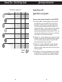
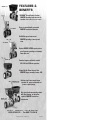
1
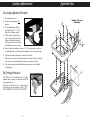
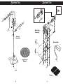
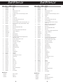
spread with confidence
Spreading Chart
Operation Guide
Service Manual
For Models:
120, 220
Parts List
It’s the spread that counts
P.O. Box 7
140 Mill Street
Urbana, IN
46990 USA
1-800-972-6130
Fax: 260-774-3416
Assembly Instructions
Assembly Instructions
For Quick and Easy Assembly - First Read Entire Procedure
Then Follow Carefully The Step by Step Instructions
Tools you will need:
1.
Medium Sized Flathead Screwdriver, Pliers
and 7/16” & 3/8” wrenches
Parts you will use:
Parts for Models: 220
Parts for Models:120
• (6)
Bolt - Hopper to Frame & Control
Tube to Hopper, 1/4-20 x 2"
Bolt - Control Brace to Hopper 1/420 x 3/4"
• (2)
Bolt - Deflector Shield to Frame 1/4
-20 x 13/4"
Bolt - Control Brace to Control Tube
& Levers to Control Tube 1/4-20 x
1 1/2"
• (1)
Bolt - Control Brace to Hopper 1/420 x 3/4"
• (3)
Bolt - On/Off Levers to Control Tube
& Brace to Control Tube 1/4-20 x 1
1/2"
• (1)
Lever Control Tube Brace
• (1)
• (3)
• (2)
Bolt - Lever Control Tube to Hopper
• (6)
Lock Nut
• (12)
Lock Nut
• (3)
Nylon Washer
• (1)
Lever Control Brace
• (1)
Plastic End Cap / Control Tube End
• (1)
Spinner Clip
• (1)
Spinner Shaft
• (1)
Hex Key for Spinner Shaft Coupler
• (1)
Spinner / Grey Plastic
• (2)
Hopper Bottom Bearing "for
Replacement"
• (1)
Mulch Spinner
• (1)
Hex Key for Spinner Shaft Coupler
• (2)
Hopper Bottom Bearing "for
Replacement"
• (9)
Nylon Washer
• (1)
Plastic End Cap / Control Tube
• (1)
Small Parts Bag with Agitator & Felt
Washer for use with grass Seed
• (2)
Set Screw 1/4-20 x 3/8" Allen for
Spinner Shaft Coupler
2
• (2)
Plastic End Cap / Frame
• (1)
Coupler for New Motor Shaft
2.
Insert Bump Bar
(1) into Frame (2),
but do not bolt
together at this
time.
* For model 120, skip
to step 4
Place Hopper
Assembly onto
Frame (2). Note:
The Rate Gate
Control Lever (4)
& the Accuway®
Control Lever (5)
go under the
frame cross
brace.
3
Assembly Instructions
3.
4.
Assembly Instructions
5.
Bolt Hopper
Assembly to frame
(2) using 4 bolts
(6) with 4 nylon
washers (7) and 4
nuts (8).
6.
Attach Lever
Control Bar (9)
to Hopper
Assembly with
2 bolts (10) and
2 nylon
washers(7) and
2 nuts (8).
7.
4
Attach the Lever
Control Brace (11)
to the Lever Control
Bar (9) with one bolt
(12) and nut (8).
Attach the opposite
end of the Control
Brace to the Hopper
with one bolt (13)
and nut (8).
Attach the Rate
Gate Control Lever
(4) to the Lever
Control Bar (9) with
2 bolts (12).
Attach the
Accuway® Control
Lever (5) to the
Control Bar with
two bolts (10) that
you used in step (6)
and fasten with two
nuts (8).
5
Assembly Instructions
8.
Assembly Instructions
10.
Attach Deflector
Shield (14) to
Frame with two
bolts (10) two
nylon washers (7)
and two nuts (8).
Attach the
Coupler (15) to
Spinner Shaft (16)
with Set Screw
(17), and opposite
end of coupler to
shaft on motor.
11.
Connect the
Control Box (18)
to the control wire
from the motor.
6
7
Linkage Adjustment
Exploded View
New Linkage Adjustment Procedure
1. Set regulator dial to 1.
2. Set lever completely to off
position.
Hopper & Frame
Assembly
6
7
3. Attach cable clamp (59) to
ground prop with 11/4” bolt
and nut and finger tighten.
6
7
6
7
12
25
5
6
7
4. Route cable through clamp,
then through swivel and then
tighten the cable clamp bolt
just enough to allow the cable
to slide back and forth easily.
4
8
9
12
8
8
46
6
7
6
5. Adjust sheath on cable so there is a 1/8” inch of control wire that
is visible between the sheath and the edge of the rate gate linkage.
11
8
8
8
7
3
13
6. Tighten the cable clamp bolt to secure the sheath.
7. Tighten the screw on the cable fastener to anchor the wire, making
sure that the rate gate linkage is pushed up against the dial.
8. Trim excess wire behind cable fastener connector when finished
(if necessary).
7
10
7
Dial Setting Information
The RATE DIAL has 9 numbers with 10 stops
between each number, for accurate control of
the spreading rate.
The dial is set with only a turn. It will automatically lock into the set position. LINE UP THE
DIAL NUMBER WITH THE DIAL INDICATOR.
8
8
14
8
1
8
8
8
2
24
24
8
9
10
Exploded View
Exploded View
37
13
38
7
7
8
22
19
22
42
8
7
13
37
36
20
7
8
8
21
8
23
20
23
17
42
13
38
7
8
7
15
22
27
8
22
22
39
8
7
45
28
22
Rate Gate
Assembly
7
22
29
36
29
28
29
29
Spinner
Assembly
25
27
4
3030
Control Box
33
33
18
16
31
5
3833
34
33
32
40
Pen Mulch™
Spinner
34
35
45
22
22
22
22
43
Screen
10
11
26
Model 120 Parts List
Item #
1
2
3
4
5
6
7
8
9
10
11
12
13
Part #
05-298-3030
05-120-3010
05-120-2212
05-120-3230
05-120-3225
05-90-0016
05-94-0064
SS-91-0004
05-120-3030
05-90-0016
05-299-3071
SS-90-0012
05-90-0051
Quantity
1
1
1
1
1
6
17
24
1
2
1
3
9
14
15
16
17
18
19
20
21
22
05-120-2211
05-98-0098
05-120-2235
05-90-0041
05-98-0061-W
05-98-0097-KLA
05-120-3020
05-120-2221
99-10-0205
1
1
1
2
1
1
2
1
12
23
24
25
26
27
28
29
30
31
32
33
34
35
36
37
38
39
40
41
42
43
44
45
46
99-10-0205
SS-94-0015
05-94-0023
05-120-3310
05-296-2215
SS-94-0007
05-94-0042
05-296-2220
05-296-0175
05-296-0280
05-90-0044
05-88-2240
05-90-0055
05-296-0110
05-296-0131
05-94-0069
SS-297-0003
05-220-0140
05-296-0115
05-94-0078
05-97-0031
05-99-0069
SS-92-0002
05-98-0089
2
2
1
1
1
3
4
1
1
1
2
1
1
1
1
1
1
1
1
1
1
1
1
1
Optional Accessories
05-220-0240
05-94-0074
05-120-3000
Description
Bump Bar
Frame
Hopper
Rate Gate Control Lever / On-Off
Accuway Control Lever
Bolt - Hopper to Frame & Lever Control Tube to Hopper 1/4-20 x 2"
Nylon Washer
Lock Nut
Lever Control Tube
Bolt - Deflector Shield to Frame, 1/4-20 x 1 3/4"
Lever Control Tube Brace
Bolt -On/Off / Accuway Levers & Brace to Control Tube 1/4-20 x 1 1/2"
Bolt - Lever Control Brace to Hopper & Motor Mount Brackets to Hopper
1/4-20 x 3/4"
Deflector Shield
Spinner Shaft Coupling For New Gear Motor
Spinner Shaft
Set Screw 1/4-20 x 3/8" Allen / For Spinner Shaft Coupler
Control Box / Variable Speed
Gear Motor
Motor Mount Brackets
Motor Mount Base Plate
Bolt - Motor Base Plate to Motor Bracket & Hopper Bottom Plate to
Hopper 1/4-20 x 1/2" Hex
Bolt - Motor to Base Plate 1/4-20 x 1/2” Hex
Plastic Plug to Frame Ends
Plastic End Cap / Control Tube End
Screen (Optional)
Hopper Bottom Plate
Hopper Bottom Bearing
Rate Gate & Diffuser Guide
Rate Gate
Diffuser Assy.
Cable Mount Bracket
Cable Fastener
Cable Retainer
Bolt for Cable Retainer 10 - 32 X 1/2"
Rate Gate Linkage
Dial
Dial Mount
Agitator Wire
Spinner / Plastic
Spinner / Mulch
Pine Tree Clip
Spinner Clip
Hex Key for Spinner Shaft Coupler
Felt Washer
T-bar Locking Knob
Stainless Steel Spinner
Hopper Cover
Calibration Tray
12
Model 220 Parts List
Item #
1
2
3
4
5
6
7
8
9
10
11
12
Part #
05-299-3040
05-220-3010
05-220-2210
05-297-0115
05-297-0110
05-90-0038
05-94-0064
SS-91-0004
05-299-3060
05-90-0016
05-299-3071
SS-90-0012
Quantity
1
1
1
1
1
6
17
24
1
2
1
3
13
05-90-0051
1
14
15
16
17
18
19
20
21
22
05-220-2250
05-98-0098
05-220-2225
05-90-0041
05-98-0061-W
05-98-0097-KLA
05-220-2215
05-220-2221
99-10-0205
1
1
1
2
1
1
2
1
12
23
24
25
26
27
28
29
30
31
32
33
34
35
36
37
38
39
40
41
42
43
44
45
46
99-10-0205
05-94-0073
05-94-0088
05-220-3050
05-297-2215
SS-94-0007
05-94-0042
05-296-2220
05-296-0175
05-297-0280
05-90-0044
05-88-2240
05-90-0055
05-296-0110
05-296-0131
05-94-0069
SS-297-0003
05-220-0140
05-296-0115
05-94-0078
05-97-0031
05-99-0069
SS-92-0002
05-98-0089
2
1
2
1
1
3
4
1
1
1
2
1
1
1
1
1
1
1
1
1
1
1
1
1
Optional Accessories
05-220-0240
05-94-0075
05-299-3600
05-94-0085
Description
Bump Bar
Frame
Hopper
Rate Gate Control Lever / On-Off
Accuway Control Lever
Bolt - Hopper to Frame & Control Tube to Hopper, 1/4-20 x 2"
Nylon Washer
Lock Nut
Lever Control Tube
Bolt - Deflector Shield to Frame 1/4 -20 x 13/4"
Lever Control Tube Brace
Bolt - On/Off / Accuway Levers & Brace to Control Tube
1/4-20 x 1 1/2"
Bolt -Lever Control Tube Brace to Hopper & Motor
Mount Brackets to Hopper 1/4-20 x 3/4"
Deflector Shield
Spinner Shaft Coupling For New Gear Motor
Spinner Shaft
Set Screw 1/4-20 x 3/8" Allen For Spinner Shaft Coupler
Control Box / Variable Speed
Gear Motor
Motor Mount Brackets
Motor Mount Base Plate
Bolt - Motor Base Plate to Motor Bracket & Hopper
Bottom Plate to Hopper 1/4- 20 x 1/2" Hex
Bolt - Motor to Base Plate 1/4- 20 x 1/2" Hex
Plastic End Cap to Control Tube
Plastic Plug to Frame Frame Ends
Screen (Optional)
Hopper Bottom Plate
Hopper Bottom Bearing
Rate Gate & Diffuser Guide
Rate Gate
Diffuser Assy.
Cable Mount Bracket
Cable Fastener
Cable Retainer
Bolt to Cable Retainer 10 - 32 X 1/2"
Rate Gate Linkage
Dial
Dial Mount
Agitator Wire
Spinner / Grey Plastic
Spinner / Mulch
Pine Tree Clip
Spinner Clip
Hex Key for Spinner Shaft Coupler
Felt Washer
T-bar Locking Knob
Stainless Steel Spinner
Hopper Cover
Extension Hopper - Doubles Capacity
Extension Hopper Cover
13
Read Before Using
WARNING: During assembly make sure that all moving parts move freely and are
unobstructed by nuts and bolts.
WARNING: REMEMBER TO ALWAYS KEEP HANDS AWAY FROM MOVING PARTS
DURING OPERATION OF THE SPREADER.
SPEED - ACCURACY - FREEDOM FROM STRIPES AND STREAKS
are yours - when you use this Spreader.
The spread width ranges from 6 ft. to 25 ft. wide, depending on the
volume/density, particle size of the material and the rate of travel.
The spread thins or feathers at the outer edges, eliminating sharp,
“Edge of spread” lines which cause stripes and streaks. Extra coverage
can be given under trees and other heavy feeding areas without showing “edge of spread” lines.
Gaps and double overlaps are less likely. Small errors in travel are forgiven and do not show.
WARNING: When spreading products containing herbicides, exercise extreme
caution with respect to careless spreading and to wind-drift.
CONTACT OF SOME PRODUCTS ON SOME PLANTS CAN BE FATAL.
Read Before Using
Rotary Agitator
Use the rotary agitator only if needed. Free-flowing, lump-free materials will not require the agitator. The rotary agitator is easily installed or
removed. Note the clockwise rotation & sweep. Place felt washer
around spinner shaft before inserting agitator. - See page 7.
OIL BEARINGS AND ALL MOVING PARTS
Make certain the spreader is running freely!
Now You are Ready to Put Material in the Hopper
• Make certain the rate gate is in closed position.
• As insurance against spill damage and spill loss, put material in the
hopper with the spreader on a walk, driveway, paper, plastic, etc.
Now You are Ready to Spread
If a dial setting is not found, use the size and weight comparison table
found on the back page.
• Spread header strips at the ends of the area OPPOSITE the direction of
spreading. This will provide a “turn-around” area, an area to re-align the
spreader for the return spread.
Determine a dial setting on the low side. If the setting proves to be
too low, cover the area more than one time. A higher setting can be
used when a proven dial setting is established.
• Example is for 6 ft. wide spread: Make the first spreading pass at onehalf the spread width from the edge of the spreading area or in this
case approximately 3 feet or one big step.
REMEMBER - Published dial settings can be approximate only. The
operation of the spreader, the condition of the material (damp or dry
or over-pulverized) and weather conditions, are all contributing factors.
• Additional spreading passes will be at the full spread width or approximately 6 feet apart.
For these reasons, it’s often a good idea to spread the area 2 times at one-half rate - in cross directions (SEE INFORMATION ON ONE-HALF
RATE DIAL SETTINGS ON REFERENCE CHART ON THE BACK PAGE.
SPREADING AT ONE-HALF RATE DIAL SETTINGS IS HIGHLY RECOMMENDED UNDER DAMP & HUMID CONDITIONS.
• TAKE A SIGHTING AT THE FAR END. Keep your eye on the sighting as
you spread. You will not need to wonder where you are or where you
have been. Continue until spreading is completed.
• Left over fertilizer can be spread under trees and other high feeding
areas without showing “edge of spread” lines.
BECOME FAMILIAR WITH THE OPERATION OF THE SPREADER
BEFORE YOU PUT MATERIAL IN THE HOPPER.
Travel at a constant speed and operate the spreader in a level
position.
Remember: Open the rate gate after the spreader is turned on at
operating speed.
Close the rate gate while spreader is still at operational speed.
14
15
Read Before Using
Cleaning the Spreader is Part of the Spreading Job.
IMMEDIATELY AFTER USE - CLEAN AND OIL THE SPREADER
• Method #1 - Wipe spreader thoroughly with an oily cloth. Oil all
bearings and bearing areas.
• Method #2 - Wash, rinse, and dry the spreader. Note: Drying
takes time. (Moisture trapped in bearing areas is slow to go.)
Immediately after drying - oil all bearings and moving parts. Make
certain all operations are thorough.
Note: Good “Dry Cleaning” is preferable to poor “Wet Cleaning”.
• It is virtually impossible to have rust and corrosion on a clean, dry,
oiled surface.
• Again - just before using - oil all bearings and moving parts.
• In storage, ideally the spreader should be hung by the handle. In
any case, do not pile weight on the spreader, as excess weight over
a period of time can distort the tires.
“Accuway” Use Instructions.
BALANCING THE SPREAD - A COMPLICATED PROBLEM WITH A SIMPLE SOLUTION
Read Before Using
Accuway - What It Does
Accuway Spread Pattern Equalizer Balances the spread
pattern - Bulls Eye - Dead to the Center of the Spreader. All
products. All spreading conditions. Skewing is eliminated.
Does not change the spread width.
VARIABLES in product, weather, spreading equipment, spreader operator, etc., and combinations of variable elements produce
VARIABLES in the spread pattern.
• VARIABLES include product size, weight, shape, surface finish,
hygroscopic or non hygroscopic composition, condition of product
(exposure to humidity, temperature, etc.)
• VARIABLES include spreading rate (light, medium, heavy).
• VARIABLES include size, shape, design of spreading spinner.
• VARIABLES include product dispensing on spreading spinner.
• VARIABLES include condition of the spreader end the spreading
spinner (product build up on the casting vanes, etc.)
HERE’S THE PROBLEM - IT’S THE VARIABLES
It’s the VARIABLES. Each variable has it’s own spread pattern
characteristics.
It’s the VARIABLES. They’re transposed and mirrored in the Spread
pattern.
TRAVEL SPEED, HUMIDITY AND CONDITION OF PRODUCT ARE
MAJOR FACTORS IN BALANCING THE SPREAD
“To Every Action There Is Always An Opposed and Equal Reaction”
(Newton’s law of motion - Sir Isaac Newton, 1642-1727.)
16
• VARIABLES include operator habits, fast or slow walking, tilting
spreader forward or backward or operating spreader in a level
attitude.
Accuway - How It Works
A slight movement of the Accuway control lever (see illustration below)
factors the variables.
Shifts the product placement on the spreading spinner.
This in turn balances the spread pattern heavier to right or heavier to
left as required.
Adjustment is very sensitive.
17
Granule Size - Dial Setting Guide
Operating Instructions
Read Before Using
Dial settings are approximate only.
Product
Lbs. per 1000 Sq. Ft.
Full Rate
Half Rate
1
3.6
3.1
2
4.0
3.5
3
4.2
3.7
2
3.7
3.2
4
4.7
4.1
6
5.2
4.5
Fine Pellets
Mixed Fine Pellets
Small Pellets
Nitrogen Pellets Med.
Med. Pellets & Granules
Med. Pellets
Large Heavy Pellets
2
3
2.2
4
4.2
3.7
6
4.5
4
1
3.5
3
2
4.2
3.7
3
4.7
4
2
3.5
3
4
4.2
3.8
6
5.2
4.5
2
3.5
3
4
4.2
3.8
6
5.2
4.5
2
3.8
3.3
4
4.9
4.1
6
5.9
4.9
Models 120 and 220
Spyker Mulch-n-more Spreaders
There are a variety of optional attachments for the model 120/220…
1. Mulch Spinner Blade… Used for spreading a variety of products
from Pellet Mulch such as PennMulch® to Dry Sand, Salt and
other difficult to spread high volume or large particle products.
With Spyker’s patent pending removable spinner blade you can
change to Mulch blade in a matter of seconds. All other spreaders
that are on the market require the removal of the hopper to
access the spinner blade which can take as long as 1/2 to 1 hour
to do. No other spreader company manufactures a “mulch basket
spinner blade” for use with high volume products.
2. Calibration Pan… Used for calibrating the turf product for accurate
spreading to reduce waste and increase effectiveness of the product. This is the latest, greatest attachment for the 120/220
series. Calibrate without moving the spreader.
3. Border Patrol… Used for guarding collars, greens, flower beds,
driveways and sidewalks from fertilizer or pesticide materials.
Stop flow to one side. Easily turned on and off with your foot while
continuing to spread.
4. Barrier Shield… For use with ice melt products and salt to deflect
the product down on to the sidewalk (3’ width pattern) essentially
converting the rotary spreader to a drop spreader for sidewalks.
18
19
Did You Know?
Operating Instructions
THERE'S MORE TO A SPREADER THAN MEETS THE EYE ––– LOTS MORE
Spreadability - Dial-a-matic regulator ensures exact spread rate. Accuway®
Spread Pattern Equalizer assures exact placement of the spread pattern - Bull's
Eye - dead to the center of the spreader. All products - All spreading conditions.
Skewing is eliminated.
Durability - Model 120/220 spreaders will survive use and abuse. Welded
stainless steel construction is double braced. Guaranteed metal gears.
Reliability - You can count on. Accuway® spread control system is so innovative,
it's patented. Is so successful it's used on all Spyker 120/220 spreaders.
A complicated problem is solved with a fundamental solution.
(Newton's law of motion: To every action there is always an opposed and equal
reaction.)
Serviceability - 24 hour replacement parts service available direct from the factory. Model 120/220 spreaders shipped set up except control bar and the hopper
connection to the frame.
Mechanized casting
came into being in
1868 when Samuel
Speicher invented the
Hand Crank "Cyclone"
Seeder.
Paul Speicher put the
hand crank seeder on
wheels in 1955.
The seed sower was a
breakthrough in field
seeding. It was hailed
as a major advancement in agricultural
implements.
20
This development ushered in a new era in
spreading and spreading products. New
products and product
forms adapted to
broadcast spreading
were developed.
Calibrating your Spyker Electric 120 and 220 Broadcast Spreaders...
1. Dial your recommended setting (or use the “Calibration Pan” to find
the most accurate setting for that particular product).
2. Start with the ‘Accuway control lever’ up or forward.
3. Begin to spread your product. As you are spreading you should be
able to see the spread pattern in front of you. Generally, all spreaders will tend to throw fertilizer heavy to the right. As you continue
to spread, (using the left lever) Accuway control, pull the Accuway
control towards you very slowly* until you begin to bring the spread
pattern dead center in front of you.
4. Once you have the spread pattern ‘dead center’, leave the left lever
alone for the rest of the time you are spreading that particular
product. There should be no reason to re-set the Accuway for that
product unless you see that the spread pattern has changed due
to bumping the lever. If it has changed slightly simply re-adjust the
pattern while you’re spreading.
Note *”slowly” means as little as 1/100 of an inch at a time. It
will not take much to change the pattern. If you radically move the
left lever Accuway control, you may impede or shut off the flow of
fertilizer or lose the Accuway position and it will be necessary to
push the lever all of the way forward and begin to bring it back
towards you slowly until the pattern is set again.
Broadcast Spreading
Broadcast spreading
is as old as early man.
In the early days of
agriculture, field seeding was accomplished
with hand cast broadcasting. The hand
cast method of seeding was a limited factor in growing field
crops that were hand
seeded.
A
‘ ccuway Control’ Instructions
In 1988 a new dimension was added to
broadcast spreading SPREAD PATTERN
CONTROL - a dead
center spread pattern
equalizer.
Spyker's Accuway®
spread pattern equalizer solves a complicated problem with a
fundamental patented
solution.
21
Operating Instructions
Read Before Using
Operating Instructions
Operating at the Mulch Setting
Changing the Spinner Blade
1. You will notice a slot in the spreader setting dial control right where
the 9 is or was located. Simply dial the setting so that the metal
guide will go through this dial slot when you move the right control
lever.
1. Simply remove the special “spring pin” from the spinner shaft that holds the
regular spinner blade onto the spinner shaft. Lift the stainless collar that
holds the shaft together.
2. The spreader opening will now move all of the way open to the
maximum opening that the spreader can achieve.
3. Slide the Mulch Basket onto the shaft, slide the collar back onto the shaft
under the blade, re-connect the shaft and slide the collar over the break in
the shaft.
3. This setting was basically designed to spread PennMulch® at
70-75 lbs. per thousand square feet at 2.5 miles per hour. It’s
easy enough to check and adjust your walking speed. See Mulch-nMore calibration instructions “Calculating your walking speed”.
4. The “all of the way open setting” can also be used to spread dry
sand, dry organic top dresses and fertilizers, salt and ice melt
products and other normally difficult to spread products.
5. When using the mulch setting you can gate the flow of the material
as you’re spreading. For salt, sand and top dress materials in
which an accurate setting is not critical simply watch the flow of
material as it comes out of the spreader. Either open more or
close off (gate the flow) until you feel comfortable with the amount
of material you are spreading. If you would like to check the flow
rate simply mark the position of the control lever with a piece of
tape and use the calibration bucket to check the coverage per
thousand square feet. (See the calibration instructions included
with the calibration bucket or “Calibrating the Mulch-n-More” on the
www.spyker.com web site.)
6. Through trials involving mass flow products such as sand and salt
we have found that using the “mulch basket” gives you the best
spread pattern. Although the spread will be slightly to the right
using the mulch basket, the actual spread of the product is even
all of the way across the effective spread width. Depending on the
type of product you’re spreading, using a standard spinner blade
the product will flow heavy to the left and give you a less than
desirable spread pattern leaving a heavy line of product a one spot
and light at another. This is the exact reason Spyker developed the
Mulch spinner blade. No other ground driven spreader has the
capability of spreading materials at these high rates because they
all use a standard spinner blade.
2. Slide the shaft upwards a few inches and remove the blade from the shaft.
4. Put the “spring pin” in the lower hole on the shaft (for the Mulch Basket)
and clip the spring onto the shaft using the hook. The “spring pin” holds the
spinner blade in place and stops the collar from moving upwards so that
the shaft will not separate.
5. Reverse instructions for replacing the regular spinner blade. The only difference would be that you must pin the regular blade using the upper hole on
the spinner shaft. It’s easy. The upper hole is for the regular spinner blade,
the lower hole is for the Mulch Basket.
LIMITED WARRANTY
This is warranted to the original purchaser only, other than used commercially,
against defects in materials and workmanship, for a period of ninety (90) days
from the date of purchase.
* For Spyker Spreaders LLC, products employing metal gear systems, pinion and bezel, these
metal gears, only not inclusive of any other parts or materials, are warranted for the life of
the spreader, not to be used for replacement or repair past original purchase.
Spyker Spreaders LLC, will not be liable for any loss, damage or expense including, but not limited, consequential or incidental damages, arising from the operation, condition or use of the item, the sole and exclusive remedy against Spyker
Spreaders LLC, being the replacement of the defective parts. This warranty
gives you specific legal rights and you may also have other rights which vary from
state to state.
THIS EXPRESS WARRANTY, WHICH IS APPLICABLE ONLY TO THE
ORIGINAL PURCHASER, IS IN LIEU OF AND EXCLUDES ALL OTHER
WARRANTIES, WHETHER EXPRESSED OR IMPLIED BY OPERATION
OF LAW OR OTHERWISE, INCLUDING ANY WARRANTY OF MERCHANTABILITY OR FITNESS FOR PARTICULAR PURPOSE.
Spyker Spreaders LLC
P.O. Box 7 • 140 Mill St. • Urbana, IN 46990
U.S.A.
22
23
FEATURES &
BENEFITS
MODEL 179
"ACCUWAY'' Spread Pattern Equalizer
ENSURES spreading dead center of the
spreader. (Indicated with "22" in model number)
Gears are unconditionally guaranteed
ENSURES trouble free operation.
20 SERIES
Dial-A-Matic spread rate control
ENSURES spreading at exact spread
rates.
90 SERIES
Optional BORDER PATROL spread pattern
cut-off prevents spreading on drive-ways,
flower beds, etc.
MODEL 88
Extension hoppers available for models
220, 299 and 20 Series spreaders.
Shipped Set-Up. Saves time and labor
ENSURES proper assembly. (except #64)
MODEL 298
Mulch Spreader
Stainless steel frames ensure longer
spreader life, easier maintenance and
present a quality image.
High grade plastic non-corroding wheels
with nylon bearings, no lubrication
required, ENSURES trouble free
maintenance.
MODEL 299
Mulch Spreader
P.O. Box 7
•
140 Mill Street
1-800-972-6130
•
•
Urbana, IN
46990
USA
Fax 260-774-3416
© 2004 Spyker Spreaders – Urbana, IN U.S.A.
05.99.0084