1
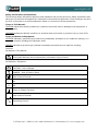
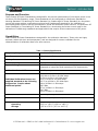
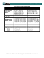
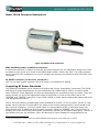
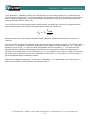
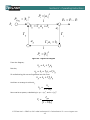
RF Coaxial Power Standards Models 1510A and 2510A Instruction and Service Manual PN# 1510A/2510A-900 Publication Date: March, 2015 REV. F 10 TEGAM WAY • GENEVA, OHIO 44041 440-466-6100 • FAX 440-466-6110 • www.tegam.com TEGAM is a manufacturer of electronic test and measurement equipment for metrology, calibration, and production test. We also provide repair, calibration, and other support services for a wide variety of test and measurement equipment including RF power sensor calibration systems, RF attenuation measurement systems, ratio transformers, arbitrary waveform generators, micro-ohmmeters, LCR meters, handheld temperature calibrators, thermometers, humidity and temperature control devices, and more. TEGAM also repairs and calibrates test and measurement equipment formerly manufactured by ElectroScientific Industries (ESI), Gertsch, Keithley Instruments, Lucas Weinschel, and Pragmatic Instruments. A complete list can be viewed on our Product Service Directory at www.tegam.com For more information about TEGAM and our products, please visit our website at www.tegam.com: or contact one of our customer service representatives at [email protected] or 800-666-1010. 10 Tegam Way, Geneva, Ohio 44041 Telephone: (440) 466-6100 Fax: (440) 466-6110 E-mail: [email protected] 10 TEGAM WAY • GENEVA, OHIO 44041 440-466-6100 • FAX 440-466-6110 • www.tegam.com Table of Contents Section I. II. Page Introduction Purpose and functions.......................................................................... 1-1 Capabilities......................................................................................... 1-1 Performance characteristics .................................................................. 1-2 Environmental information ................................................................... 1-2 List of items furnished ......................................................................... 1-3 List of additional items required for operation and maintenance ................ 1-3 Preparation for calibration or repair and shipping .................................... 1-4 Expedite Repair Form .......................................................................... 1-5 Warranty information........................................................................... 1-6 TEGAM contact information .................................................................. 1-6 Preparation for Use and Installation Unpacking & Inspection........................................................................ 2-1 Recommended Operating Environment .................................................. 2-1 III. Principles of Operation IV. Operating Instructions V. VI. VII. Power Measurements ........................................................................... 3-1 Principles of DC Substitution ................................................................. 3-1 Temperature Variable Resistance .......................................................... 3-1 Power Splitters ................................................................................... 3-1 Controlling Thermistor Temperature ...................................................... 3-2 Front Panel Connectors ........................................................................ 4-1 Calculating Calibration Factors .............................................................. 4-2 Relationship between k, gamma. And effective efficiency ......................... 4-7 Maintenance and Servicing Maintenance ....................................................................................... 5-1 Care and Handling of Assemblies........................................................... 5-1 Connector Torque ................................................................................ 5-2 Connector Care and Cleaning ................................................................ 5-3 Preparation for Shipment Returning power standard for service..................................................... 7-1 Repacking for shipment ....................................................................... 7-1 Storage Temperature and other environmental limitations ................................... 8-1 10 TEGAM WAY • GENEVA, OHIO 44041 440-466-6100 • FAX 440-466-6110 • www.tegam.com Safety Information & Precautions: The following safety information applies to both operation and service personnel. Safety precautions and warnings may be found throughout this instruction manual and the equipment. These warnings may be in the form of a symbol or a written statement. Below is a summary of these precautions. Terms in This Manual: CAUTION statements identify conditions or practices that could result in damage to the equipment or other property. WARNING statements identify conditions or practices that could result in personal injury or loss of life. Terms as Marked on Equipment: CAUTION indicates a personal injury hazard not immediately accessible as one reads the marking, or a hazard to property including the equipment itself. DANGER indicates a personal injury hazard immediately accessible as one reads the marking. Symbols: As Marked in This Manual: ! This symbol denotes where precautionary information may be found. As Marked on Equipment: ! CAUTION – Risk of Danger DANGER – Risk of Electric Shock Earth Ground Terminal l On O Off Frame or Chassis Terminal Earth Ground Terminal Alternating Current 10 TEGAM WAY • GENEVA, OHIO 44041 440-466-6100 • FAX 440-466-6110 • www.tegam.com Section I – Introduction Purpose and Function These Coaxial RF Power Standards are designed for the precise measurement of microwave power in the 10 MHz to 50 GHz frequency range. These standards can be configured as a Reference Standard or Working Standard. The Working RF Power Standard (or Feedthrough RF Power Standard) is a thermistor mount with power splitter combination employed as a Feedthrough standard for the calibration of terminating power sensors such as thermoelectric, diode and thermistor power sensors. The Reference RF Power Standard (or Terminating RF Power Standard) is a terminating thermistor mount used for the calibration of Feedthrough standards and applications that require direct measurement of RF power. Capabilities These Coaxial RF Power Standards are designed for the calibration laboratory. These units are highly accurate, stable with time and temperature, and are designed for use as a standard for the characterization of calibration factors for other sensors. Frequency Range Table 1.1 General Specifications 10 MHz to 50 GHz Max Power 25 mW (+14 dBm) RF Impedance 50 Ohms nominal Power Linearity Dynamic Range <0.1% from 1 to 10 mW -20 dBm to +14 dBm typical (Depends on noise floor and resolution of DC instruments) Calibration Factor Drift <0.5% per year Individual Calibration factors are supplied standard at the following frequencies. Inquire about additional points. 10 to 100 MHz in 10 MHz steps 100 MHz to 2 GHz in 50 MHz steps 2 GHz to 4 GHz in 100 MHz steps 4 to 12.4 GHz in 200 MHz steps 12.75 to 18 GHz in 250 MHz steps 18 to 26 GHz in 1 GHz steps 26.5 GHz 27 to 34 GHz in 1 GHz steps 34.5 GHz 35 to 50 GHz in 1 GHz steps Thermistor DC Bias Power 40 mW (nominal) Thermistor Resistance at Bias 200 Ohms (set by balancer) Temperature Operating Storage +15° to +30° C (+59° to +86° F) -55° to +75° C (-67° to +167° F) 10 TEGAM WAY • GENEVA, OHIO 44041 440-466-6100 • FAX 440-466-6110 • www.tegam.com 1-1 Section I – Introduction Table 1.2 2510A/1510A Individual Specification Model Frequency Range 2510A 10 MHz to 50 GHz 10 MHz to 100 MHz: 0.01 100 MHz to 2 GHz: 0.02 2 GHz to 12.4 GHz: 0.04 12.4 GHz to 18 GHz: 0.06 18 GHz to 26.5 GHz: 0.10 26.5 GHz to 40 GHz: 0.15 40 GHz to 50 GHz: 0.25 11 dB (typical) 1510A 10 MHz to 50 GHz 10 MHz to 100 MHz: 0.0066 100 MHz to 2 GHz: 0.0267 2 GHz to 12.4 GHz: 0.1356 12.4 GHz to 18 GHz: 0.2249 18 GHz to 26.5 GHz: 0.3200 26.5 GHz to 50 GHz: 0.3389 +/-1.0% from 0.01 to 0.04 GHz +/-1.25% from 0.05 to 4.0 GHz +/-1.5% from 4.20 to 12.0 GHz +/-2.2% from 12.2 to 17.5 GHz +/-2.5% from 17.75 to 26.5 GHz +/-3.0% from 27.0 to 44.0 GHz +/-4.0% from 45.0 to 50.0 GHz +/-1.2% +/-1.4% +/-1.7% +/-2.3% +/-2.6% +/-3.2% +/-4.2% Connectors APC 2.4 mm Female APC 2.4 mm Male Weight Physical Dimensions Height Width Depth 2.9 kg (6.3 lb) 544.3 g (1.2 lb) 10.5 cm (4.1 in) 21.7 cm (8.5 in) 33.8 cm (13.3 in) 7.2 cm (2.8 in.) 8.2 cm (3.2 in.) 13.8 cm (5.4 in.) Typical Equivalent Source Match |Γ|(V/V) Loss from Input Port to DUT Port Calibration Factor Accuracy (typical) N/A from from from from from from from 0.01 to 0.04 GHz 0.05 to 4.0 GHz 4.20 to 12.0 GHZ 12.2 to 17.5 GHz 17.75 to 26.5 GHz 27.0 to 44.0 GHz 45.0 to 50.0 GHz 10 TEGAM WAY • GENEVA, OHIO 44041 440-466-6100 • FAX 440-466-6110 • www.tegam.com 1-2 Section I – Introduction Items Included with 1510A and 2510A Item Part Number Technical (Operation and Maintenance) Manual 1510A/2510A-900 Calibration Certificate with Data N/A Table 1.2–Packing List Additional items (required and optional) for operation and maintenance Required: • • • TEGAM Model 1830A, 1806A, or 1806 RF Power Meter o 1830A Cable (CA-21-15/48) o 1806A Cable (CA-28-48) o 1806 Cable (CA-29-48) RF Signal Generator o 10 MHz to 50 GHz o Minimum power level 17 dBm at 50 GHz Torque Wrench o Torque wrench, 8mm, 8 in-lbs (2510-910-01) Optional: • • • • • • • RF Amplifier SureCAL Software (P/N SureCAL-PM) Rack Mount Kit o (Single - P/N 1830-910) o (Dual - P/N 1830-911) VNA o 2-port o 50 GHz TEGAM 1510A (For calibration of TEGAM 2510A) Transport Case o 1510 RF Power Standard (1500-910) o 1830A, F113X & 2510A (2500-910) Adapters o Coax adapter, 2.4mm (F) to 2.92mm (M) with Data (1510-911-01) o Coax adapter, 2.4mm (F) to 3.5mm (M) with Data (1510-912-01) o Coax Adapter, 2.4mm (M) to 2.92mm (F) with Data (2510-911-01) o Coax Adapter, 2.4mm (M) to 3.5mm (F) with Data (2510-912-01) o Coax Attenuator, 2.4mm (M to F) 30dB with Data (2510-913-01) 10 TEGAM WAY • GENEVA, OHIO 44041 440-466-6100 • FAX 440-466-6110 • www.tegam.com 1-3 Section I – Introduction Preparation For Calibration Or Repair Service Once you have verified that the cause for the Coaxial RF Power Standards malfunction cannot be solved in the field and the need for repair and calibration service arises, contact TEGAM customer service to obtain an RMA, (Returned Material Authorization), number. You can contact TEGAM customer service via the TEGAM website, www.tegam.com or by calling 440.466.6100 (All Locations) OR 800.666.1010 (United States Only). The RMA number is unique to your instrument and will help us identify you instrument and to address the particular service request by you which is assigned to that RMA number. Of even importance, a detailed written description of the problem should be attached to the instrument. Many times repair turnaround is unnecessarily delayed due to a lack of repair instructions or of a detailed description of the problem. This description should include information such as measurement range, and other instrument settings, type of components being tested, are the symptoms intermittent, conditions that may cause the symptoms, has anything changed since the last time the instrument was used, etc. Any detailed information provided to our technicians will assist them in identifying and correcting the problem in the quickest possible manner. Use a copy of the Repair and Calibration Service form provided on the next page. Once this information is prepared and sent with the instrument to our service department, we will do our part in making sure that you receive the best possible customer service and turnaround time possible. 10 TEGAM WAY • GENEVA, OHIO 44041 440-466-6100 • FAX 440-466-6110 • www.tegam.com 1-4 Section I – Introduction EXPEDITE REPAIR & CALIBRATION FORM Use this form to provide additional repair information and service instructions. The Completion of this form and including it with your instrument will expedite the processing and repair process. RMA#: Serial Number: Technical Contact: Additional Contact Info: Instrument Model #: Company: Phone Number: Repair Instructions: Evaluation Calibration Only Repair Only Repair & Calibration Z540 (Extra Charge) Detailed Symptoms: Include information such as measurement range, instrument settings, type of components being tested, is the problem intermittent? When is the problem most frequent?, Has anything changed with the application since the last time the instrument was used?, etc. 10 TEGAM WAY • GENEVA, OHIO 44041 440-466-6100 • FAX 440-466-6110 • www.tegam.com 1-5 Section I – Introduction Warranty TEGAM, Inc. warrants this product to be free from defects in material and workmanship for a period of three years from the date of shipment. During this warranty period, if a product proves to be defective, TEGAM Inc., at its option, will either repair the defective product without charge for parts and labor, or exchange any product that proves to be defective. TEGAM, Inc. warrants the calibration of this product for a period of 1 year from date of shipment. During this period, TEGAM, Inc. will recalibrate any product, which does not conform to the published accuracy specifications. In order to exercise this warranty, TEGAM, Inc., must be notified of the defective product before the expiration of the warranty period. The customer shall be responsible for packaging and shipping the product to the designated TEGAM service center with shipping charges prepaid. TEGAM Inc. shall pay for the return of the product to the customer if the shipment is to a location within the country in which the TEGAM service center is located. The customer shall be responsible for paying all shipping, duties, taxes, and additional costs if the product is transported to any other locations. Repaired products are warranted for the remaining balance of the original warranty, or 90 days, whichever period is longer. Warranty Limitations The TEGAM, Inc. warranty does not apply to defects resulting from unauthorized modification or misuse of the product or any part. This warranty does not apply to fuses, batteries, or damage to the instrument caused by battery leakage. Statement of Calibration This instrument has been inspected and tested in accordance with specifications published by TEGAM Inc. The calibration of this instrument is traceable to the International System of Units (SI) through the National Institute of Standards and Technology (NIST) or other recognized National Metrology Institutes, by comparison to equipment and standards maintained in the laboratories of TEGAM Inc. Document publishing dates may lag product changes. Visit www.tegam.com to download the latest version of this manual. Contact Information: TEGAM INC. 10 TEGAM WAY GENEVA, OHIO 44041 PH: 440.466.6100 FX: 440.466.6110 EMAIL: [email protected] WEB: http://www.tegam.com 10 TEGAM WAY • GENEVA, OHIO 44041 440-466-6100 • FAX 440-466-6110 • www.tegam.com 1-6 Section II – Preparation for Use and Installation Unpacking & Inspection Each Coaxial RF Power Standards is put through a series of electrical and mechanical inspections before shipment to the customer. Upon receipt of your instrument unpack all of the items from the shipping carton and inspect for any damage that may have occurred during transit. Report any damaged items to the shipping agent. Retain and use the original packing material for reshipment if necessary. Upon Receipt, inspect the carton for the following items: Table 2.1 Packing List Item Part Number Model 2510A or 1510A Coaxial RF Power 2510A or 1510A Standards Technical (Operation and Maintenance) Manual 1510A/2510A-900 Calibration Certificate with Data N/A Mounting The Model 2510A is shipped with four plastic feet mounted to the bottom cover. When any of these models are placed on a bench or table, the feet support the instrument. For rack mounting of Model 2510A use rack mount kit, (Single) P/N 1830-910 – (Dual) P/N 1830-911. The Model 1510A is shipped without any type of rack mounting equipment the new design allows for use as a terminating sensor and it low weight of 544.3 g (1.2 lb) reduces any stress on connectors. Only use with Proper Equipment: CAUTION: These RF Power Standards are designed to be used with TEGAM Models 1830A, 1806A, and 1806 only. Connecting this device to any other type of circuit or may result in permanent damage to the components. Additionally, the heater elements used for the internal heater are designed to be used only with the heater control circuits found in TEGAM Models 1830A, 1806A, and 1806. Connecting these heater elements to any other circuit or device may result in damage. Contact TEGAM for any questions regarding instruments that are compatible with these RF Power Standards. Use in Proper Environment Normal calibration laboratory practice dictates that the environment should be closely controlled. This will minimize errors introduced by temperature and humidity changes. A nominal temperature of +23°C (+73.4°F) provides a good working condition. A tolerance of ±1°C gives an ideal temperature spread. Controlled temperatures also stabilize the aging process of the standards. CAUTION: The RF Power Standards have a specified operating temperature range of +15° to +30° C (+59° to +86° F). Operating beyond these limits can affect the accuracy of the instruments and damage internal circuitry. CAUTION: When an RF Power Standard is to be stored for extended periods, pack the instrument into a container. Place container in a clean, dry, temperature-controlled location. If instrument is to be stored in excess of 90 days, place desiccant with items before sealing container. The safe environmental limits for storage are -55° to +75° C (-67° to +167° F) at less than 95% non-condensing relative humidity. 10 TEGAM WAY • GENEVA, OHIO 44041 440-466-6100 • FAX 440-466-6110 • www.tegam.com 2-1 Section II – Preparation for Use and Installation Do Not Use in Explosive Environments CAUTION: The 1510A and 2510A are not designed for operation in explosive environments. Do Not Operate Without Covers WARNING: This device should be operated with all panels and covers in place. Operation with missing panels or covers could result in personal injury. 10 TEGAM WAY • GENEVA, OHIO 44041 440-466-6100 • FAX 440-466-6110 • www.tegam.com 2-2 Section III – Principles of Operation Theory of RF Measurements with the 2510A and 1510A NOTE: The TEGAM 1830A, 1806A and 1806 RF Power Meter are referenced several times in this section. The TEGAM 1830A, 1806A, and 1806 RF Power Meters are the only way to bias, temperature control and monitor the 2510A and 1510A. Power Measurements RF power is measured in terms of a power change across the precision resistance leg of a TEGAM 1830A, 1806A, 1806 Bridge Circuit. A digital voltmeter measures voltage across the precision resistance leg which can be used to determine the power. The total power applied to the thermistor leg (in the RF Power Standard) of the Type IV Bridge equals the sum of both DC and RF power. The precision resistor leg only has DC power applied to it. Thus, the RF power introduced to the thermistor is directly proportional to the change in DC power across the precision resistor. Principle of DC Substitution The RF Power Standards use the principle of DC substitution to measure RF power. DC substitution refers to the measurement of RF power according to the amount of DC power that must be substituted for the RF power in a bolometer in order to cause equivalent thermal effects. Since some of the RF power applied to the input of the power standard is lost by reflection and other causes before it is applied to the thermistor element, a calibration factor for the standard is to determine the actual level of RF power. TEGAM Coaxial RF Power Standards are configured to provide a path for RF energy via a coaxial line. DC Bias is introduced from the Bias terminals to the thermistors. Temperature Variable Resistance Each RF Standard contains a pair of thermistor beads whereby the resistance changes as a function of temperature. Thermistor bead temperature is a function of the combined DC and RF power applied to the beads and the ambient temperature surrounding the beads. The level of power applied to the beads is controlled externally. A heating element, controlled by an external controller, provides ambient temperature stability. SENSOR BRIDGE BALANCER T VOUT T Figure 3.1 Thermistor and Bridge Balancer Figure 3.1 depicts the thermistor assembly electrical configuration. DC biasing of the dual thermistor beads to 100 ohms each provides a nominal 50 ohm parallel RF resistance and a 200 ohm series DC resistance. A DC blocking capacitor and bypass capacitors isolate DC from RF signals. Filtering capacitors provide low VSWR in the lower end of the frequency range. Application of approximately 40 mW of power to the thermistor beads produces a 200 ohm DC resistance. As the power applied to the thermistor beads 10 TEGAM WAY • GENEVA, OHIO 44041 440-466-6100 • FAX 440-466-6110 • www.tegam.com 3-1 Section III – Principles of Operation increases, their effective resistance values decrease. This is due to the negative temperature coefficient of the beads. Initially, the beads are DC biased to 200 ohms. Application of RF power increases the power level present at the beads and causes the effective resistance value of the beads to drop. The bridge circuit of the power meter reduces DC power until the initial effective resistance value is restored (200 ohms). The total amount of DC power removed is proportional to the amount of RF power that was introduced. Quantitatively, the total power applied to the thermistor beads equals the sum of the two types of power. Power Splitter The Models 2510A contain a two-element resistive power splitter. The T-shaped divider contains a series 50 ohm resistor in each of the two legs. The test port is an APC 2.4 mm precision female connector. Use of the splitter in a closed loop configuration that applies constant power causes the common point (divider) to become a constant voltage point. This means the source impedance at both splitter output ports is determined by the 50 ohm resistor and the output connector. This provides very good source match. In addition, the power is split equally between the two ports. Controlling Thermistor Temperature Since thermistor mounts are temperature sensitive devices, it is necessary to eliminate or minimize the effects of changes in the ambient temperature. This is accomplished by thermally isolating the mount, raising its temperature with a heater element to a level higher than the ambient temperature, and maintaining that level by means of an external temperature controller. The heater element electrical assembly as illustrated in Figure 3.2. The proper temperature is determined by the characteristics of the thermistor beads. Figure 3.2 Simplified of RF Power Standards Internal Heater 10 TEGAM WAY • GENEVA, OHIO 44041 440-466-6100 • FAX 440-466-6110 • www.tegam.com 3-2 Section IV – Operating Instructions General The TEGAM RF Power Standards are designed to be employed as the fourth arm of a bridge configuration. These units are designed as the sensing element in RF power calibration and measurement systems. These systems employ other electronic elements to effect control of the measurement routines. An example of this type of system is the TEGAM PMX50-001 Power Sensor Calibration System. Proper use of these standards and the TEGAM PMX50-001 is further documented in other TEGAM Operation and Service Manuals. The Working RF Power Standard (Model 2510A) are feedthrough mount-splitter combinations are use to calibrate thermoelectric, diode, and thermistor power sensors. The Reference RF Power Standards (Model 1510A) are terminating thermistor mounts commonly used as a reference standard for calibrating working standards. Both types of standards are used with the TEGAM 1830A, 1806A and 1806. Model 2510A Connector Descriptions Figure 4.1 TEGAM 2510A Connectors RF IN connector APC 2.4 mm female connector connects to signal generator output. The RF power that comes in this connector is applied equally to the DUT and the power standard. The fact that equal RF power is applied to both the power standard and the DUT is what allows the determination the calibration factor of the DUT. There is typically 6 dB nominal with a max of 10.5 db of insertion loss in the RF in path of the power splitter, plus the insertion loss the standard. BIAS VOLTAGE/Heater combination connector A combined connection is used to connect the thermistor element to a DC Substitution bridge circuit and the heater control circuit as is found in the TEGAM Model 1830A, 1806A, and 1806. The bridge operates on the principal of DC substitution, so only DC voltages and currents are present at these terminals when connected. SENSOR connector APC 2.4 mm female coaxial connector provides the RF power to the DUT. The RF power applied to RF IN connector is applied equally to the DUT and the internal thermistor mount. The fact that equal RF power is applied to both the power standard and the DUT is what allows the calibration factor of the DUT to be determined. 10 TEGAM WAY • GENEVA, OHIO 44041 440-466-6100 • FAX 440-466-6110 • www.tegam.com 4-1 Section IV – Operating Instructions Model 1510A Connector Descriptions Figure 4.2 TEGAM 1510A Connectors BIAS VOLTAGE/Heater combination connector A combined connection is used to connect the thermistor element to a DC Substitution bridge circuit and the heater control circuit as is found in the TEGAM Model 1830A, 1806A, and 1806. The bridge operates on the principal of DC substitution, so only DC voltages and currents are present at these terminals when connected. RF INPUT connector (on the front, not shown) APC 2.4 mm male coaxial connector where RF power to be measured is applied. Connecting RF Power Standards The TEGAM RF Standards are an element of a system and is not a “stand-alone” instrument. The 2510A and 1510A RF Power Standard can only be connected to the TEGAM 1830A, 1806A, and 1806. Unlike other TEGAM RF Power Standards, the bias and temperature are connected through one cable. To do this, simply connect one end of the appropriate cable to the 2510A or 1510A and the other end to the “SENSOR” and “HEATER” connection of the 1830A, 1806A, or 1806. Use the appropriate cables that meet your equipment application 1. The RF IN on the Working (Feedthrough) Power Standards is an APC 2.4 mm connector. An APC 2.4 mm female coaxial connector is connected to the output of the chosen signal generator, which should be 50 Ohm nominal impedance. A low loss coaxial cable is recommended to avoid an excessive power loss. These Models have an additional female coaxial connector called the “SENSOR” port. This connector is actually one of the arms of the power splitter (described in Section III Principles of Operation). The DUT is connected to this port for calibration. When the Working RF Power Standard is being calibrated, the 1 When connecting to the 1806 or 1806A the FLOAT/GROUND switch should be in the FLOAT (down) position. 10 TEGAM WAY • GENEVA, OHIO 44041 440-466-6100 • FAX 440-466-6110 • www.tegam.com 4-2 Section IV – Operating Instructions Reference RF Power Standard is connected to this port. This connector is an 2.4 mm female. Proper care, cleaning, alignment, and torquing of coaxial connectors should be practiced to make accurate measurements, reduce insertion loss and extend the life of the connectors. The RF input on the Reference (Terminating) Power Standards (Model 1510A) is a male 2.4 mm connector that is connected to the RF power source to be measured. Again, proper care, cleaning, alignment, and torquing of coaxial connectors should be practiced to make accurate measurements, reduce insertion loss, improve repeatability, and extend the life of the connectors. Once cabling has been correctly installed, there are no further operator adjustments to be made to the RF Power Standards. However, allow at least two hours for the heater in the RF Standard to reach its operating temperature. Additionally, it is recommended that once the BIAS VOLTAGE terminals are connected, the DC Substitution Bridge should be on for one hour before measurements are taken 2. Calculating Calibration Factors When using a RF Power Meter with a RF Power Sensor to make a RF Power Measurement the user must know that the measurement is accurate and there is traceability to a known standard. All diode, thermoelectric, and thermistor power sensors have calibration factors associated to particular frequencies that are used to insure an accurate power measurement. Technicians and engineers use these calibration factors when making measurements but where do these calibration factors really come from. Calibration factor of a terminating power sensor, if it is a DC-substitution sensor, relates the change in DC substituted power to the total RF power incident on the sensor. For this purpose, incident means all of the RF propagating toward the sensor reference plane, including power that is subsequently reflected. On the signal flow diagram (figure 4.3), the incident power is 𝑃𝑖 = |𝑎𝑙 |2 . Calibration factor of a feed-through power calibration setup, again if the monitor is a DC-substitution sensor, relates the change in DC substituted power in the monitor to the power delivered out of the DUT port into a load of exactly the nominal characteristic impedance of the system, or 𝑍0 . If we think of the feed-through DUT port as the output of a leveled generator, then the output into a perfect load is 𝑃𝑔𝑧0 . So for a terminating sensor (using the “M” subscript following Weinschel part numbering): 𝑘𝑀 = 𝑃𝑆𝑢𝑢𝑢 𝑃𝑖 𝑘𝐹 = 𝑃𝑆𝑆𝑆𝑆 𝑃𝑔𝑍0 And for a feed-through standard, (using “F” to indicate “feedthrough”): Where: kM = Calibration factor of the Terminating Mount kF = Calibration factor of the Feed-through Mount PSubM = Power measured terminating mount PSubF = Power measured Feed-through mount 2 When connecting a 1510A or 2510A to an 1806 or 1806A; in addition to a 2 hour warm up time, operator should observe stability in the bias voltage. Bias voltage stability refers to less than 50uV change per 30 minutes as a general guideline. The error light does not apply when connecting the 1510A or 2510A to the 1806A. 10 TEGAM WAY • GENEVA, OHIO 44041 440-466-6100 • FAX 440-466-6110 • www.tegam.com 4-3 Section IV – Operating Instructions In all calibrations, calibration factors are transferred from a terminating reference, to a feed-through stand, and then into the DUT. In some procedures, this transfer occurs all in one session, and in others time is saved by transferring into the feed-through once and then using that feed-through calibration factor to calibrate DUT for some time. In a perfect world, the terminating sensor would present a perfect load, and then by reorganizing the above two definitions with incident and output power equal, we would have, 𝑘𝑀 = 𝑘𝐹 𝑃𝑆𝑆𝑆𝑆 𝑃𝑆𝑆𝑆𝑆 Because power sensors are always imperfect loads, additional analysis and sometimes correction is required. Figure 4.1 shows a signal flow diagram of two one-port devices connected together. The left-hand port is the “output”, or “generator” port and is designated on the diagram using the subscript, “g”. The righthand port is the “input”, or “load” port and is designated using the subscript “l”. It’s clear from the diagram that port reflections dominated by the Gamma vectors generally cause the power that the generator port would output into an ideal load, 𝑃𝑔𝑧0 , to not be equal to the power 𝑃𝑖 , incident on the load. We really have to take into account the combination of reflections, or “port match” to come up with a general understanding of calibration transfer. Start with the signal flow diagram. In this case, a Generator “g” is represented by an ideal source “s”, and its port reflection, and the sensor is termed the load, “l”. 10 TEGAM WAY • GENEVA, OHIO 44041 440-466-6100 • FAX 440-466-6110 • www.tegam.com 4-4 Section IV – Operating Instructions Pi = a 1 bg = Γg a g + bs 2 bs Pd = Pi − Pr a Γg Γ Γ a = b ag 1 Pr = b 2 Figure 4-3 - Signal Flow Diagram From the diagram, But also, 𝑏𝑔 = 𝑏𝑠 + Γ𝑔 𝑎𝑔 𝑎𝑔 = 𝑏𝑙 = Γ𝑙 𝑎𝑙 = Γ𝑙 𝑏𝑔 So substituting the second equation into the first: And then re-arrange to collect bg: 𝑏𝑔 = 𝑏𝑠 + Γ𝑙 Γ𝑔 𝑏𝑔 𝑏𝑔 = 𝑏𝑠 1 − Γ𝑙 Γ𝑔 2 Now rewrite as power, substituting in 𝑃𝑔𝑧0 = |𝑏𝑠 |2 , and 𝑃𝑖 = �𝑏𝑔 � : 𝑃𝑖 = 𝑃𝑔𝑧0 2 �1 − Γ𝑙 Γ𝑔 � 10 TEGAM WAY • GENEVA, OHIO 44041 440-466-6100 • FAX 440-466-6110 • www.tegam.com 4-5 Section IV – Operating Instructions Armed with this last result, and calling the Feed-through stand (F subscript) the “generator” (g subscript) and terminating sensor (M subscript) the “load” (l subscript), and substituting in the definitions for cal factor from earlier, we get the more general equation for transferring between a feed-through and a terminating sensor: 𝑘𝑀 = 𝑘𝐹 𝑃𝑆𝑆𝑆𝑆 |1 − Γ𝑀 Γ𝐹 |2 𝑃𝑆𝑆𝑆𝑆 Where: kM = Calibration factor of the Terminating Mount kF = Calibration factor of the Feed-through Mount PSubM = Power measured terminating mount PSubF = Power measured Feed-through mount ΓΜ = Gamma Correction full vector data Terminating Mount ΓΦ = Gamma Correction full vector data Feed-through Mount Now in this general equation, the Gamma terms are the reflection scattering parameter of the respective port noted in the subscript. Gamma is a complex vector with scalar values denoting the real and imaginary magnitudes: Γ ≡ 𝜌∠𝜙 = 𝜌 cos 𝜙 + i𝜌sin 𝜙 In the general transfer equation, the term, |1 − Γ𝑀 Γ𝐹 |2 is the scalar “gamma correction” or “port match” term. Inside the absolute value brackets, however, is a vector subtraction. Expanding out to make the angles explicit, this becomes: |1 − 𝜌𝑀 𝜌𝐹 cos(𝜙𝑀 + 𝜙𝐹 ) − 𝑖 𝜌𝑀 𝜌𝐹 sin(𝜙𝑀 + 𝜙𝐹 )|2 2 Where the i represents √−1, or the “imaginary” component. The absolute value, or length of a vector, is given by the Pythagorean formula, which is the square root of the square of the magnitudes of the real and imaginary components. It’s convenient that we are looking for the square of the magnitude, so we don’t have to worry about the square root part. Our correction term becomes the scalar, (1 − 𝜌𝑀 𝜌𝑀 cos(𝜙𝑀 + 𝜙𝐹 ))2 + (𝜌𝑀 𝜌𝐹 sin(𝜙𝑀 + 𝜙𝐹 ))2 When the squares are evaluated, this expands to: 1 − 2𝜌𝑀 𝜌𝐹 cos(𝜙𝑀 + 𝜙𝐹 ) + 𝜌𝑀 2 𝜌𝐹 2 cos 2 (𝜙𝑀 + 𝜙𝐹 ) + 𝜌𝑀 2 𝜌𝐹 2 sin2 (𝜙𝑀 + 𝜙𝐹 ) 10 TEGAM WAY • GENEVA, OHIO 44041 440-466-6100 • FAX 440-466-6110 • www.tegam.com 4-6 Section IV – Operating Instructions Noting that if we collect the two terms beginning with 𝜌𝑀 2 𝜌𝐹 2 , we get, 1 − 2𝜌𝑀 𝜌𝐹 cos(𝜙𝑀 + 𝜙𝐹 ) + 𝜌𝑀 2 𝜌𝐹 2 (cos 2 (𝜙𝑀 + 𝜙𝐹 ) + sin2 (𝜙𝑀 + 𝜙𝐹 )) The term, cos 2(𝜙𝑀 + 𝜙𝐹 ) + sin2 (𝜙𝑀 + 𝜙𝐹 ) is always identically equal to 1, so the final simplified equation becomes, 1 − 2𝜌𝑀 𝜌𝐹 cos(𝜙𝑀 + 𝜙𝐹 ) + 𝜌𝑀 2 𝜌𝐹 2 Or combining this result with the general transfer equation, 𝑘𝑀 = 𝑘𝐹 𝑃𝑆𝑆𝑆𝑆 (1 − 2𝜌𝑀 𝜌𝐹 cos(𝜙𝑀 + 𝜙𝐹 ) + 𝜌𝑀 2 𝜌𝐹 2 ) 𝑃𝑆𝑆𝑆𝑆 If we look at the scalar result of the mismatch term, the “1” part is what would happen if at least one of the ports was “perfect”, or had no reflection. In that case, one of the 𝜌 is zero. The right-most element has magnitude of 𝜌4 , which is typically so much smaller than the middle term that it can be ignored for most connections. The middle part, 2𝜌𝑀 𝜌𝐹 cos(𝜙𝑀 + 𝜙𝐹 ), contains the bulk of the impact of port mismatch. Since it is multiplied by k, the sensitivity to this change is equal to k, or about 1. In an UNCORRECTED transfer, this part represents the probable error of the transfer. Since we can’t know the angles in an uncorrected transfer, we let cos() take its limits of +/- 1, and say that the uncertainty of the uncorrected transfer is 2𝜌𝑀 𝜌𝐹 . That is a little pessimistic, because that is worst-case rather than probable, but it’s what the industry usually does. Unless the rhos were measured on a scalar analyzer, we have to use manufacturer’s worst-case values. Some common power sensor calibration practices do not always use gamma correction. An argument could probably be made that this was a reasonable practice at lower frequencies. We typically see this at 18 GHz and lower. A value of 0 would be inserted for ΓΜ making that portion of the formula “1”. This would make the formula look like: 𝑘𝑀 = 𝑘𝐹 𝑃𝑆𝑆𝑆𝑆 𝑃𝑆𝑆𝑆𝑆 This revision of the original formula assumes many things that are not necessarily true. Things that may not necessarily show up at lower frequencies but will certainly show up at higher frequencies where connectors change from the very rugged N-type connector to the more sensitive 3.5 mm and 2.4 mm connectors. By looking at Figure 4.4 we can get a practical visualization of the relationship between calibration factor, gamma and effective efficiency. 10 TEGAM WAY • GENEVA, OHIO 44041 440-466-6100 • FAX 440-466-6110 • www.tegam.com 4-7 Section IV – Operating Instructions Figure 4.4 - Relationship between calibration factor, gamma, and effective efficiency 10 TEGAM WAY • GENEVA, OHIO 44041 440-466-6100 • FAX 440-466-6110 • www.tegam.com 4-8 Section V– Maintenance and Servicing Maintenance Care and Handling of Assemblies To ensure accurate measurements and optimal performance of TEGAM products, the microwave coaxial cable assemblies used in system and test setups must be properly used and maintained. Proper connections, routine inspection of all cables, and cleaning of the connectors are extremely important procedures which can prolong the longevity and accuracy of equipment. Cable Inspection Routinely check external cables for signs of cracked insulation, dents, twists, flattening, signs of jacket abrasion, or other signs of abuse. Wrinkles in the jacket indicate that the minimum bend radius has been exceeded. Most often, this occurs near the marker tubes and connectors. Also inspect the connector interfaces for the following: • Bent pins (male). • Bent or missing tines (female). • Worn or chipped plating. • Damaged or displaced dielectric inserts. • Thread damage. • Folded or mushroomed outer interface rims. • Mushroomed pin shoulders (male) or tine ends (female). • Score lines on pins and outer interface rims visible to the unaided eye. • Recessed or protruding pins. It is advisable to clean the connectors prior to inspection to make subtle damage more apparent. If any of the above is noted, replace the assembly before its further use results in equipment damage. Also inspect the mating connectors for similar damage. Inspect the connector interface for signs of debris. Debris may be in the form of: • Plating chips or other metal particles. • Dust or dirt. • Oily films. • Other miscellaneous foreign particles. Making Initial Connections Exercise caution when mating cables. Poor connections lead to poor system performance. They can also damage not only the cable assembly, but more significantly, front or rear panel connectors on the equipment itself which may be more difficult to repair. Aligning Connectors Align the center lines of two connectors before actual mating. Male retaining nuts contain a small amount of necessary play which may make it possible to mate the threads without the pins being properly aligned. Pin misalignment can damage pins and dielectric inserts. Mating Connectors Gently mate the connectors by hand, taking care not to force the coupling nut at the slightest resistance. It is often possible to feel whether or not the pins are mated. If the coupling nut is difficult to turn, either the pins are not mated, the coupling nut is cross-threaded, or one of the connectors has been damaged by excess torque. 10 TEGAM WAY • GENEVA, OHIO 44041 440-466-6100 • FAX 440-466-6110 • www.tegam.com 5-1 Section V– Maintenance and Servicing Never hold a male connector coupling nut stationary while screwing a female connector into it. This rotation can erode the plating and damage both the outer interface rim as well as the pin. If the pins become locked, serious damage can result to both the equipment and the cable assembly. Over-Torque Once connectors have been properly mated, apply only the proper amount of torque. Over-torque damages both connectors involved. Also, a connector which has been damaged by over-torque, in turn, damages every connector to which it is subsequently mated. It usually leads to poor system performance as well. Over-torque can cause: • • • • • • • • Bent pins. Recessed or protruding pins. Recessed or protruding dielectrics. Chipped plating. Damaged coupling threads. Coupling nut retaining ring damage. Mushroomed outer interface shells. Mushroomed pin shoulders. Proper Torque of a APC 2.4 mm Hex Nut To mate a connector of the hex-nut type, always use a torque wrench set to the correct torque value. Tighten the connector slowly until the wrench snaps. Tightening too quickly can cause the wrench to exceed its set limit. Do not snap the wrench more than once as this also causes over-torque. CONNECTOR RECOMMENDED TORQUE APC 2.4 mm 8.0 in/lbs Figure 6.1 Recommended APC 2.4 mm Torque 10 TEGAM WAY • GENEVA, OHIO 44041 440-466-6100 • FAX 440-466-6110 • www.tegam.com 5-2 Section V– Maintenance and Servicing CLEANING CONNECTOR INTERFACES Use the following guidelines in cleaning connector interfaces: • Do not use chlorinated solvents including common tap water. These solvents are extremely penetrating and sometimes ruin otherwise good devices and assemblies. • Moisten a cotton swab with isopropyl alcohol. Roll the swab on a paper towel to remove excess. • Use the moistened cotton swab to wipe away debris. Do not try to dissolve the debris by overwetting the swab. • Repeat the cleaning process using additional swabs as necessary. If metallic particles are embedded in the dielectric, use an eyeglass and a sharp pick in an attempt to dislodge them. Swab again. • When satisfied that the interfaces are clean, blow them dry with dry compressed air, or preferably dry nitrogen (pressurized spray cans work well). Do not use breath. • Clean the mating connectors. These may be the source of the debris. 10 TEGAM WAY • GENEVA, OHIO 44041 440-466-6100 • FAX 440-466-6110 • www.tegam.com 5-3 Section VI– Preparation for Shipment Returning 2510A/1510A for Service Use the information in this section if you need to return your Power Standard to TEGAM. Package 2510A/1510A for Shipment Use the following steps to package the Power Standard for shipment to TEGAM for service: 1. Fill the EXPEDITE REPAIR & CALIBRATION FORM (found in Section I) and attach it to the Power Standard. Please be as specific as possible about the nature of the problem. Send a copy of any or all of the following information: o Any error messages that appeared on the power meter display. o Any information on the performance of the Power Standard. 2. Use the original packaging materials or a strong shipping container. The carton must be both large enough and strong enough to accommodate the power standard and allow at least three to four inches on all sides of the power standard for packing material. 3. Seal the shipping container securely with strong nylon adhesive tape. 4. Mark the shipping container “FRAGILE, HANDLE WITH CARE” to ensure careful handling. CAUTION: 2510A/1510A damage can result from using packaging materials other than those specified. 5. Retain copies of all shipping papers. NOTE: Refer to page 1-6 of the introduction for information on how to obtain a RMA from TEGAM. 10 TEGAM WAY • GENEVA, OHIO 44041 440-466-6100 • FAX 440-466-6110 • www.tegam.com 6-1 Section VII – Storage Storage When an RF Power Standard is to be stored for extended periods, pack the instrument into a container. Place container in a clean, dry, temperature-controlled location. If instrument is to be stored in excess of 90 days, place desiccant with items before sealing container. The safe environmental limits for storage are -55° to +75° C (-67° to +167° F) at less than 95% non-condensing relative humidity. 10 TEGAM WAY • GENEVA, OHIO 44041 440-466-6100 • FAX 440-466-6110 • www.tegam.com 7-1