1
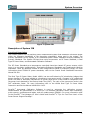
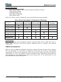
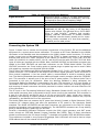
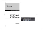
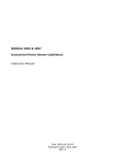
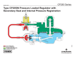
TEGAM INC.
System IIB
POWER SENSOR CALIBRATION SYSTEM
System Overview
PN# SYSIIB-903-01CD
Publication Date: September 2006
REV. A
NOTE: This user’s manual was as current as possible when this product was manufactured. However, products are
constantly being updated and improved. Because of this, some differences may occur between the description in this
manual and the product received.
TEGAM is a manufacturer of electronic test and measurement equipment for metrology,
calibration, and production test. We also provide repair, calibration, and other support
services for a wide variety of test and measurement equipment including RF power sensor
calibration systems, RF attenuation measurement systems, resistance standards, ratio
transformers, arbitrary waveform generators, micro-ohmmeters, LCR meters, handheld
temperature calibrators, thermometers, humidity and temperature control devices, and
more.
TEGAM also repairs and calibrates test and measurement equipment formerly manufactured
by Electro-Scientific Industries (ESI), Gertsch, Keithley Instruments, Lucas Weinschel, and
Pragmatic Instruments. A complete list can be viewed on our Product Service Directory at
www.tegam.com
For more information about TEGAM and our products, please visit our website at
www.tegam.com: or contact one of our customer service representatives at
[email protected] or 800-666-1010.
Ten Tegam Way
Geneva, Ohio 44041
Telephone: (440) 466-6100
Fax: (440) 466-6110
E-mail: [email protected]
System Overview
Figure 1 System IIB
Description of System IIB
Functional Description
The TEGAM System IIB is a precision power measurement system that measures microwave power
within the frequency bandwidth of the thermistor standard(s) being used in the system. The
primary application of this system is for automated power sensor calibration directly traceable to
primary standards. The System IIB has three main components: an RF Power Standard, a Dual
Type IV Power Meter, and Automated Calibration Software.
The RF Power Standards are temperature controlled thermistor based RF power sensors which
come in a two basic configurations: Terminating Reference Standards and Feedthrough Working
Standards. There are different models of both configurations based on frequency range. For more
information about TEGAM RF power standards, refer to the Coaxial Power Standards Instruction
Manual IM-300.
The Dual Type IV Power Meter, Model 1806A, has two self balancing DC substitution bridges that
detect changes in RF power applied to a thermistor type power sensor. Changes in DC substituted
power are used to accurately calculate an RF power level which is then used for comparison with
the power level detected by the Device Under Test (DUT). The ratio of the two power levels is the
DUT calibration factor. For more information refer to the 1806A Dual Type IV Power Meter
Instruction and Service Manual 1806A-901-01CD.
SureCAL® Automated Calibration Software is used to automate the calibration process.
Measurements are transmitted on a serial bus. The software calculates results and uncertainty,
prints reports, certificates and labels, and will update sensor EPROM’s. For more information refer
to the SureCAL® Test Manager V5 User’s Guide and SureCAL®’s “Tips for First-Time User’s of the
Power Sensor Support Package”.
System IIB RF Power Sensor Calibration System
1
System Overview
Physical Description
All System IIB packages include:
1806A with ANSI/NCSL Z540-1-1994 Compliant Calibration with Data
SYSII-SureCal software
138-645A accessory kit
Three 1583-3 GPIB cables
1585-1008 RF cable
Refer to the Table 1 below for additional items included with each system package.
Model
(Description)
SYSIIB-k18
(100 kHz to 18 GHz)
SYSIIB-k18B
(100 kHz to 18 GHz)
Table 1 Instruments Specific to Each System IIB Package
F1130
M1130
F1135
M1135
(Working Standard (Reference Standard (Working Standard
100 kHz to 18 GHz) 100 kHz to 18 GHz) 0.01 to 26.5 GHz)
X
X
X
(10 MHz to 26.5 GHz)
SYSIIB-26B
(10 MHz to 26.5 GHz)
(100 kHz to 26.5 GHz)
SYSIIB-k26B
(100 kHz to 26.5 GHz)
1820
(Mount Heater for
Two Mounts)
X
SYSIIB-26
SYSIIB-k26
(Working Standard
0.01 to 26.5 GHz)
X
X
X
X
X
X
X
X
X
Specifications
Refer to the Coaxial Power Standards Instruction Manual IM-300 and the 1806A Dual Type IV
Power Meter Instruction and Service Manual 1806A-901-01CD for physical and electrical
specifications.
Additional equipment
Table 1.2 lists the additional equipment required to calibrate RF power sensors with the System
IIB. The description for each piece of equipment listed states the minimum recommended
requirements for that piece of equipment. There may be many models that meet the minimum
requirements; it is up to the operator to select the specific model. Measurement uncertainty will
vary depending on the additional equipment used. Please refer to the specifications for the
particular model to get that information.
2
System IIB RF Power Sensor Calibration System
System Overview
Signal Generator
DVM
RF Power Meter
IBM compatible PC
Table 1.2 Additional Equipment Required
Continuous Wave, 6 dBm to 12 dBm output power,
Frequency Range compatible to standard(s); two may
be required to cover entire Frequency Range.
DC Volts, 6½-digit minimum resolution.
Compatible with the device under test.
Pentium class processor 200MHz, 32MB RAM,
WINDOWS 95, 98, NT, Me, 2000, or XP Operating
System with utilities, 300 MB Hard Drive, 8X CD ROM
Drive to load SureCAL® software and periodic
updates, National Instruments or Hewlett Packard
IEEE-488 Bus controller board, parallel port for report
printing (unless connected to a local area network),
and serial port for label printer.
Connecting the System IIB
Figure 2 shows how to connect the functional components of the System IIB and the additional
equipment for a typical power sensor calibration. To connect an RF Power Standard to the 1806A,
the heater in the standard must be connected to the 1806A’s heater control connector. To do this,
simply connect one end the appropriate cable to the “TEMP” or heater connector on the standard
and the other end to the “TEMP” connector on the 1806A. For Models F1125, F1130, and F1135 use
cable P/N 1000008, for Models M1125, M1130, and M1135 use the cable P/N CBL-F1125-48. Both
types of cables are supplied with the 1806A. Next, the BIAS VOLTAGE red and black connectors are
cabled to the BIAS VOLTAGE red and black connectors on the TEGAM Model 1806A. The BIAS
VOLTAGE connectors are 5-way binding posts so banana plugs or spade lugs can be used. Cables
with spade lug connectors are supplied with the 1806A.
The RF IN on the Feedthrough Working Standards (Models F1125, F1130, F1135) is an SMA female
coaxial connector. It is connected to the output of the chosen signal generator, which should be 50
Ohm nominal impedance. A low loss coaxial cable is recommended to avoid an excessive power
loss. The Working Standards have another additional female coaxial connector called the “SENSOR”
port. This connector is actually one of the arms of an RF power splitter. The Device Under Test is
connected to this port for calibration. When the Working Standard is being calibrated, the
Terminating Reference Standard is connected to this port. This connector is an N type female on
the Models F1125 and F1130 and a 3.5 mm female on the F1135. Proper care, cleaning, alignment,
and torquing of coaxial connectors should be practiced to reduce insertion loss and extend the life
of the connectors.
The RF input on the Terminating Reference Power Standards (Models M1125, M1130, M1135) is a
male coaxial connector that is connected to the RF power source to be measured. This connector is
a type N on the M1125 and M1130 and is a 3.5 mm on the M1135. Again, proper care, cleaning,
alignment, and torquing of coaxial connectors should be practiced to reduce insertion loss, improve
repeatability, and extend the life of the connectors.
The Model 1806A does not measure the RF power level directly. Instead, a Digital Voltmeter (DVM)
measures DC voltages before and after the application of RF power to the thermistor based
standard. The 1806A VOLTMETER red and black connectors are connected to the DVM DC voltage
positive and negative input connectors respectively. The VOLTMETER connectors are 5-way binding
posts so banana plugs or spade lugs can be used.
SureCAL® Automated Calibration Software controls the DVM, signal generator, and DUT power
meter through an IEEE-488 General Purpose Interface Bus (GPIB). Each of these instruments
should be connected to the PC where SureCAL® is installed using quality IEEE-488 GPIB bus cables.
Three cables are included in every System IIB package. Each instrument will need to have a unique
GPIB address that will be entered into SureCAL®.
System IIB RF Power Sensor Calibration System
3
4
GPIB
TEMP
System IIB RF Power Sensor Calibration System
BIAS
VOLTAGE
TEMP
RF Output
V+
V-
VOLTMETER
Signal Generator
DVM or DMM
READY
ERROR
ON
TEST
OFF
READY
ERROR
BIAS
VOLTAGE
VOLTMETER
ON
TEST
OFF
Model 1806A
GPIB
GPIB
GPIB
RVG
PC Running
SureCal
Measurement from SUT
Frequency and Power Level Commands
TEMP
Dual Type IV Power Meter
Measured Cal Transfer DC
RVG
RF
BRIDGE B
DUT
Figure 2 Typical Setup for Calibrating RF Power Sensors with the System IIB
O
POWER
I
TEGAM
SENSOR
RF TRANSFER STANDARD MODEL F1130
BRIDGE A
BIAS VOLTAGE
RF IN
TEGAM
Power Meter
System Overview
System Overview
Operation
Once the standard(s) has been correctly connected to the 1806A, allow at least 2 hours for the
standard to reach operating temperature after connecting the heater. The READY indicator on the
1806A will illuminate once the mount has reached its operating temperature. Allow at least one
hour after the BIAS VOLTAGE terminals are connected before taking any measurements. The
SureCAL® software included in the System IIB takes care of all the measurement and mathematic
operations necessary to characterize an RF power sensor. The proceeding paragraphs are for
information only.
The System IIB does not measure the RF power level directly. Instead, it uses a technique called
DC substitution to determine RF power through DC voltage measurements. A Digital Voltmeter
(DVM) measures DC voltages before and after the application of RF power to the thermistor based
standard. The amount of RF power detected by the thermistor is derived from those voltage
measurements. The cal factor for the DUT is determined by dividing the power read by DUT power
meter by the RF power detected by the standard. For more details refer to the 1806A Dual Type IV
Power Meter Instruction and Service Manual 1806A-901-01CD and the Coaxial Power Standards
Instruction Manual IM-300.
It may be necessary to use an adapter or attenuator to calibrate a particular power sensor. If the
sensor’s power range is below 0 dBm (1 mW) then an attenuator is needed. If the sensor does not
have a male connector that is the same type as the SENSOR port of the Working Standard then an
adapter would be needed. A 50 to 75 Ohm matching pad is needed to calibrate 75 Ohm sensors.
Any device placed between the SENSOR connector and the DUT will affect the calibration results
and its loss (attenuation) must be characterized and corrected for. A kit containing some adapters
and attenuators along with correction data (P/N 138-645A) is included with the System IIB. The
characterization data is provided in a format that the SureCAL® software can use to correct for
losses in the device.
Due to the high repeatability of the RF Power Transfer Standards and the accuracy of the Type IV
Bridge, the major sources of error stem from the uncertainty of the calibration factor of the
standard and impedance mismatch. When an RF Power Standard is calibrated, an uncertainty is
reported for each calibration point. This uncertainty figure is one of the largest contributors to the
uncertainty budget for the calibration at the next level. Impedance mismatch causes some of the
RF power to be reflected back from one device to another; thus, the maximum amount of RF power
is not transferred from one device to another. Reflection coefficient of an RF device is a vector
quantity that describes how much its impedance varies from the nominal (50 Ohms). The reflection
coefficient for TEGAM RF Power Transfer Standards is included as part of the factory calibration
data. If both the magnitude and phase angle of the reflection coefficient are known for the DUT,
then Gamma corrections can be applied to the calibration factor. Applying Gamma corrections to
the calibration factor reduces the total uncertainty of the calibration by eliminating the impedance
mismatch term.
System IIB RF Power Sensor Calibration System
5
System Overview
Contacting Tegam
In the event of any questions or concerns regarding the System IIB, contact TEGAM. An apparent
malfunction of the system may be corrected over the phone or by e-mail. Contact TEGAM using the
following:
Tegam, Incorporated
Ten Tegam Way
Geneva, OH 44041 USA
ww.tegam.com
800-666-1010 toll-free
440-466-6100 phone
440-466-6110 fax
[email protected] e-mail
DO NOT send any instruments back to the factory without prior authorization. When it is necessary
to return an item, contact TEGAM customer service to obtain an RMA, (Returned Material
Authorization), number. You can contact TEGAM customer service via the TEGAM website,
www.tegam.com or by calling 440.466.6100 OR 800.666.1010.
The RMA number is unique to your instrument and will help us identify your instrument and to
address the particular service request by you which is assigned to that RMA number. Of even more
importance is a detailed written description of the problem, which should be attached to the
instrument. Many times repair turnaround is unnecessarily delayed due to a lack of repair
instructions or lack of a detailed description of the problem.
Warranty
TEGAM, Inc. warrants its products to be free from defects in material and workmanship for a period
of 1 year from the date of shipment. During this warranty period, if a product proves to be
defective, TEGAM, Inc., at its option, will either repair the defective product without charge for
parts and labor, or exchange any product that proves to be defective.
TEGAM, Inc. warrants the calibration of its products for a period of 1 year from date of shipment.
During this period, TEGAM, Inc. will recalibrate any product, which does not conform to the
published accuracy specifications.
In order to exercise this warranty, TEGAM, Inc., must be notified of the defective product before
the expiration of the warranty period. The customer shall be responsible for packaging and
shipping the product to the designated TEGAM service center with shipping charges prepaid.
TEGAM Inc. shall pay for the return of the product to the customer if the shipment is to a location
within the country in which the TEGAM service center is located. The customer shall be responsible
for paying all shipping, duties, taxes, and additional costs if the product is transported to any other
locations. Repaired products are warranted for the remaining balance of the original warranty, or
90 days, whichever period is longer.
Warranty Limitations
The TEGAM, Inc. warranty does not apply to defects resulting from unauthorized modification or
misuse of the product or any part. This warranty does not apply to fuses, batteries, or damage to
the instrument caused by battery leakage.
6
System IIB RF Power Sensor Calibration System
System Overview
Statement of Calibration
TEGAM’s instrument have been inspected and tested in accordance with specifications published by
TEGAM, Inc. The accuracy and calibration of this instrument are traceable to the United States
National Institute of Standards and Technology through equipment which is calibrated at planned
intervals by comparison to certified standards maintained in the laboratories of TEGAM, Inc.
System IIB RF Power Sensor Calibration System
7