1
IM-303A
IM-303A
Model 8311 Attenuator Unit
Operation & Service Manual
Model 8311
SmartStep Programmable Attenuator Units
This documentation may not be reproduced in any form, for any
purpose unless authorized in writing by Aeroflex / Weinschel, Inc.
© Aeroflex / Weinschel, Inc.
Frederick, Maryland
2003 - 2010
Manual Rev.
M (9-28-10)
Aeroflex
/ Weinschel
1
SAFETY SUMMARY
SAFETY SUMMARY
• To minimize shock hazard, the instrument chassis
DEFINITIONS.
The following definitions apply to WARNINGS,
CAUTIONS, and NOTES found throughout this manual.
WARNING
must be connected to an electrical ground. Using
the supplied three-conductor power cable ensures
that the instrument can be firmly connected to the
ac power source and electrical ground at a
grounded power outlet. If using a 3-2 wire
adapter be sure to connect the ground lead to earth
ground.
• Use the buddy system any time work involving
An operating or maintenance procedure, practice,
statement, condition, etc., which, if not strictly
observed, could result in injury and/or death of
personnel. Do not proceed beyond a WARNING
symbol until all the indicated conditions have been
fully understood and/or met.
active high voltage components is required. Turn
OFF the power before making/breaking any
electrical connection. Regard any exposed
connector, terminal board, or circuit board as a
possible shock hazard. DO NOT replace any
component or module with power applied.
• If test conditions to live equipment are required,
ground the test equipment before probing the
voltage or signal to be tested.
CAUTION
• Personnel working with or near high voltage
should be familiar with modern methods of
resuscitation.
An operating or maintenance procedure, practice,
statement, condition, etc., which, if not strictly
observed, could result in damage or destruction of the
equipment or long-term health hazards to personnel.
Do not proceed beyond a CAUTION symbol until all
the indicated conditions have been fully understood
and/or met.
NOTE
An essential operating or maintenance procedure,
condition, or statement that must be highlighted.
• DO NOT wear jewelry (rings, bracelets, metal
watches, and/or neck chains) while working on
exposed equipment. Be very cautious about
using hand tools near exposed backplanes, bus
bars, and/or power supply terminals. Use
properly insulated tools. When making test
connections to the power supply terminals and
bus bars, use only insulated probe tips.
• Verify that the instrument is set to match the
available line voltage and the correct fuse is
installed.
• DO NOT install substitute parts or perform any
GENERAL PRECAUTIONS.
The following are general precautions that are not related
to any specific procedure and, therefore, do not appear
elsewhere in this publication. These are precautions that
personnel must understand and apply during various phases of
instrument operation or service.
WARNING
unauthorized modification to this instrument.
Contact Weinschel Corporation to acquire any
information on replacement parts or returning
the instrument for repair. Unauthorized
modification can cause injury to personnel and/or
destruction of the instrument.
• Operating personnel must not remove instrument
covers. Component replacement or adjustments
MUST BE performed by qualified service
personnel.
• DO NOT operate the instrument near or in the
presence of flammable gases or fumes.
• Potentially lethal voltages are present in this
instrument. Serious shock hazards from voltages
above 70 volts may exist in any connector,
chassis, or circuit board. Observe the following
precautions:
DETAILED PRECAUTIONS.
The following WARNINGS, CAUTIONS and NOTES
appear throughout the text of this manual and are repeated here
for emphasis.
i
SAFETY SUMMARY
NOTE
CAUTION
• All procedures and/or steps identified as
must be followed exactly as written and
according to industry accepted ESDS device
handling procedures. Failure to comply WILL
RESULT in ESDS damage.
• DO NOT use a nylon bristle brush in the solvent
as the bristles may dissolve and cause damage to
the circuit card or component.
DO NOT return any instrument or component to
Weinschel Corporation without receiving prior
factory authorization.
SAFETY SYMBOLS.
The following symbols are used to identify safety hazards
found throughout this publication and/or located on the
instrument.
• DO NOT use ultrasonic cleaning on parts or
assemblies containing electrical or electronic
components.
• DO NOT bend pins of electrical connectors
when using fiber-bristle brush.
CAUTION
HIGH VOLTAGE
• Compressed air used for cleaning and/or drying
can create airborne particles that may enter the
eye. Goggles/faceshields should be worn. DO
NOT direct air stream towards self or other
personnel. Pressure should be restricted to a
maximum of 15 psi to avoid personal injury.
• Under no circumstances should a wire brush, steel
wool, or abrasive compound be used on any
surface. Using these items will cause extensive
damage to the instruments surface.
ii
WARNING
HIGH
VOLTAGE
Model 8311 Attenuator Unit
IM-303A
TABLE OF CONTENTS
1. GENERAL INFORMATION.................................................................................................................................................... 5
1-1. PURPOSE ........................................................................................................................................................................................... 5
1-2. SCOPE ............................................................................................................................................................................................... 5
1-3. EQUIPMENT DESCRIPTION .......................................................................................................................................................... 5
1-4. USING THE 8311 .............................................................................................................................................................................. 5
1-5. UNPACKING AND INSPECTION ................................................................................................................................................... 6
1-6. RESHIPMENT INSTRUCTIONS ..................................................................................................................................................... 6
1-7. STORAGE INSTRUCTIONS ............................................................................................................................................................ 6
1-8. RELATED MANUALS ..................................................................................................................................................................... 7
1-9. ELECTROSTATIC DISCHARGE SENSITIVE (ESD)..................................................................................................................... 7
1-10. ABBREVIATIONS & ACRONYMS .............................................................................................................................................. 7
1-11. SAFETY CONSIDERATIONS........................................................................................................................................................ 7
1-12. POWER REQUIREMENTS ............................................................................................................................................................ 7
1-13. ENVIRONMENTAL REQUIREMENTS ........................................................................................................................................ 7
2. SPECIFICATIONS ................................................................................................................................................................................... 8
2-1. GENERAL SPECIFICATIONS ......................................................................................................................................................... 8
2-2. PHYSICAL DIMENSIONS ............................................................................................................................................................... 9
2-3. CONFIGURATIONS\RF SPECIFICATIONS ................................................................................................................................... 9
3. INSTALLATION .................................................................................................................................................................... 10
3-1. RACKMOUNTING ......................................................................................................................................................................... 10
3-2. INTIAL SETUP ............................................................................................................................................................................... 10
3-3. INPUT/OUTPUT OPTIONS ............................................................................................................................................................ 10
3-3.1. POWER ENTRY MODULE ASSEMBLY ................................................................................................................................... 11
3-3.2. CHANNEL PORT CONNECTORS.............................................................................................................................................. 11
4. FRONT PANEL CONTROLS & INDICATORS .................................................................................................................. 12
5. REMOTE OPERATION ........................................................................................................................................................ 13
5.1. IEEE-488 INTERFACE BUS CONNECTOR .................................................................................................................................. 13
5-2. GPIB ADDRESS/SERIAL COMMUNICATIONS SETTINGS................................................................................................. 13-14
5-3. IEEE-488 (GPIB) BUS OPERATION ............................................................................................................................................. 15
5-4. SERIAL OPERATION .................................................................................................................................................................... 16
5-4.1. RS-232 OPERATION ................................................................................................................................................................... 17
5-4.2. RS-422/485 OPERATION ............................................................................................................................................................ 18
5-5. STATUS REPORTING............................................................................................................................................................... 19-20
5-6. GENERAL SYNTAX STRUCTURE .............................................................................................................................................. 20
5-6.1. SYNTAX OF QUERIES ............................................................................................................................................................... 20
5-6.2. SYNTAX OF COMMANDS ................................................................................................................................................... 20-21
5-6.3. OUTPUT DATA FORMAT .......................................................................................................................................................... 21
5-6.4. NOTATIONAL CONVENTION .................................................................................................................................................. 21
5-7. 488.2 COMMON COMMANDS ................................................................................................................................................ 22-23
5-8. GENERAL COMMANDS .......................................................................................................................................................... 24-25
Aeroflex / Weinschel
2
Model 8311 Attenuator Unit
IM-303A
6. GENERAL CIRCUIT DESCRIPTION ............................................................................................................................. 26-27
6-1. POWER SUPPLY ASSEMBLY ....................................................................................................................................................... 26
6-2. STATUS DISPLAYS AND SWITCH CONTROL ASSEMBLY.................................................................................................... 26
6-3. SMARTSTEP INTERFACE ASSEMBLY ...................................................................................................................................... 26
6-4. RF SECTION ................................................................................................................................................................................... 27
7. MAINTENANCE ................................................................................................................................................................... 28
7-1. INSPECTION ................................................................................................................................................................................... 28
7.2. PREVENTIVE MAINTENANCE .................................................................................................................................................... 28
7.3. SPECIAL CLEANING INSTRUCTIONS ....................................................................................................................................... 28
7-3.1. MICROWAVE COAXIAL CABLE ASSEMBLIES ........................................................................................................ 28
7-3.2. CIRCUIT CARDS AND MODULES ............................................................................................................................... 28
7-3.3. MACHINED SURFACES AND HARDWARE ............................................................................................................... 29
7-3.4. CHASSIS CLEANING ................................................................................................................................................................. 29
7-3.5. CONNECTOR CLEANING.............................................................................................................................................. 29
7.4. LINE VOLTAGE FUSE REPLACEMENT ..................................................................................................................................... 30
8. REPLACAEBLE PARTS LIST .............................................................................................................................................. 31
8-1. UNDERSTANDING REFERENCE DESIGNATORS .................................................................................................................... 31
8-2. ORDERING INFORMATION ......................................................................................................................................................... 32
8-3. DRAWING NUMBER ..................................................................................................................................................................... 31
8-4. REPLACEABLE PARTS LIST ....................................................................................................................................................... 31
8-4.1. REFERENCE DESIGNATOR .......................................................................................................................................... 31
8-4.2. DESCRIPTION ................................................................................................................................................................. 31
8-4.3. PART NUMBER ............................................................................................................................................................... 31
8-4.4. VENDOR PART NUMBER ............................................................................................................................................. 31
8-5.5. CAGE CODE .................................................................................................................................................................... 31
8-4.6. ASSEMBLY AND COMPPONET LOCATION .............................................................................................................. 31
8311-1-6-R, ATTENUATOR UNIT ASSEMBLY REPLACEABLE PARTS LIST (P/N 193-7301-1) .................................................. 32
8311-1-6-F, ATTENUATOR UNIT ASSEMBLY REPLACEABLE PARTS LIST (P/N 193-7301-2) .................................................. 33
8311-38-6-F, ATTENUATOR UNIT ASSEMBLY REPLACEABLE PARTS LIST (P/N 193-7302-2) ................................................ 34
8311-38-12-T, ATTENUATOR UNIT ASSEMBLY REPLACEABLE PARTS LIST (P/N 193-7302-8) .............................................. 35
8311-137-6-F, ATTENUATOR UNIT ASSEMBLY REPLACEABLE PARTS LIST (P/N 193-7303-2) .............................................. 36
8311-137-6-R, ATTENUATOR UNIT ASSEMBLY REPLACEABLE PARTS LIST (P/N 193-7303-12) ............................................ 37
8311-202-2-F, ATTENUATOR UNIT ASSEMBLY REPLACEABLE PARTS LIST (P/N 193-7305-2) .............................................. 38
8311-202-3-F, ATTENUATOR UNIT ASSEMBLY REPLACEABLE PARTS LIST (P/N 193-7305-3) .............................................. 39
8311-204-6-F, ATTENUATOR UNIT ASSEMBLY REPLACEABLE PARTS LIST (P/N 193-7304-2) .............................................. 40
8311-352-3-R, ATTENUATOR UNIT ASSEMBLY REPLACEABLE PARTS LIST (P/N 193-7306-13) ............................................ 41
8311-352-4-R, ATTENUATOR UNIT ASSEMBLY REPLACEABLE PARTS LIST (P/N 193-7306-14) .......................................... 42
8311-352-6-F, ATTENUATOR UNIT ASSEMBLY REPLACEABLE PARTS LIST (P/N 193-7306-2) .............................................. 43
8311-352-9-T, ATTENUATOR UNIT ASSEMBLY REPLACEABLE PARTS LIST (P/N 193-7306-9) .............................................. 44
BASIC MODEL 8311 ASSEMBLY REPLACEABLE PARTS LIST (P/N 193-8051) ........................................................................... 45
BASIC MODEL 8311 (+5 V) ASSEMBLY REPLACEABLE PARTS LIST (P/N 193-8051-1) ............................................................ 46
9. APPLICATIONS .................................................................................................................................................................... 47
10. ACCESSORIES .................................................................................................................................................................... 47
11. CONTACTING AEROFLEX / WEINSCHEL. ................................................................................................................... 47
Aeroflex / Weinschel
3
Model 8311 Attenuator Unit
IM-303A
12. AEROFLEX / WEINSCHEL WARRANTY ...................................................................................................................... 48
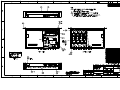
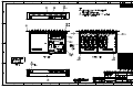
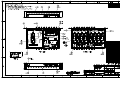
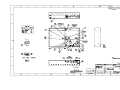
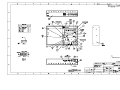
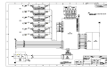
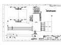
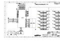
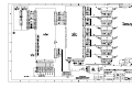
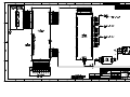
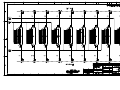
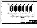
13. ASSEMBLY/WIRING DIAGRAMS
8311-1-6-F, ATTENUATOR UNIT ASSEMBLY DIAGRAM ............................................................................................. 193-7301-2A
8311-38-6-F, ATTENUATOR UNIT ASSEMBLY DIAGRAM ........................................................................................... 193-7302-2B
8311-38-12-T, ATTENUATOR UNIT ASSEMBLY DIAGRAM ......................................................................................... 193-7302-8D
8311-137-6-F, ATTENUATOR UNIT ASSEMBLY DIAGRAM ......................................................................................... 193-7303-2D
8311-137-6-R, ATTENUATOR UNIT ASSEMBLY DIAGRAM ........................................................................................ 193-7303-12C
8311-202-2-F, ATTENUATOR UNIT ASSEMBLY DIAGRAM ......................................................................................... 193-7305-2D
8311-202-3-F, ATTENUATOR UNIT ASSEMBLY DIAGRAM ......................................................................................... 193-7305-3A
8311-204-6-F, ATTENUATOR UNIT ASSEMBLY DIAGRAM ....................................................................................... 193-7304-12A
8311-352-3-R, ATTENUATOR UNIT ASSEMBLY DIAGRAM ........................................................................................ 193-7036-13A
8311-352-4-R, ATTENUATOR UNIT ASSEMBLY DIAGRAM ........................................................................................ 193-7036-14B
8311-352-6-F, ATTENUATOR UNIT ASSEMBLY DIAGRAM .......................................................................................... 193-7036-2B
8311-352-9-T, ATTENUATOR UNIT ASSEMBLY DIAGRAM ......................................................................................... 193-7306-9C
BASIC MODEL 8311 ASSEMBLY REPLACE DIAGRAM .................................................................................................... 193-8051A
BASIC MODEL 8311 (+5 V) ASSEMBLY DIAGRAM ....................................................................................................... 193-8051-1A
MODEL 8311 WIRING DIAGRAM ......................................................................................................................................... 193-8102B
MODEL 8311 WIRING DIAGRAM ......................................................................................................................................... 193-8108A
MODEL 8311 (+5V) WIRING DIAGRAM ............................................................................................................................... 193-8114B
MODEL 8311 (+5V) WIRING DIAGRAM ............................................................................................................................... 193-8120C
MODEL 8311 WIRING DIAGRAM (193-352-9-T) .................................................................................................................. 193-8129C
ICD, SPECFICATIONS 8311-1-X-X......................................................................................................................................... 089-3594A
ICD, SPECFICATIONS 8311-38-X-X....................................................................................................................................... 089-3584C
ICD, SPECFICATIONS 8311-137-6-R ...................................................................................................................................... 089-3724B
ICD, SPECIFICATIONS 8311-137-6-X .................................................................................................................................... 089-3599C
ICD, SPECFICATIONS 8311-20X-X-X .................................................................................................................................... 089-3574C
ICD, SPECFICATIONS 8311-352-X-X ..................................................................................................................................... 089-3868C
Aeroflex / Weinschel
4
Model 8311 Attenuator Unit
IM-303A
1. GENERAL INFORMATION:
1-1 PURPOSE: This manual contains setup and operation information for the Aeroflex / Weinschel’s 8311 Series of
SmartStepAttenuator Units. The manual also provides component location, reference designators, part numbers,
and nomenclature to identify all the assemblies and sub-assemblies of the Attenuator Unit.
1-2 SCOPE: This manual is to be used in conjunction with the operation and maintenance of a 8311 Series
SmartStep™ Attenuator Unit. The manual also provides a description of each assembly; assembly parts list; block
diagrams: and general maintenance procedures to maintain the instrument.
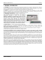
1-3 EQUIPMENT DESCRIPTION: Aeroflex / Weinschel’s 8311
Series SmartStep Attenuator Units represents a new concept in
programmable attenuation for bench test and subsystem
applications. Standard 8311 designs house and control various
Weinschel Programmable Attenuator Models (3200T, 150T, and
4200 Series) via front panel controls or standard communications
interfaces including GPIB (IEEE-488) and RS-232/RS-422
/RS485. Special configurations also exists where the RF section is
designed to specific customer requirements which can contain to
multiple programmable attenuations used in conjunction with other
coaxial devices such as switches, power combiners, directional
couplers, and filters creating single or multi-channel subsystems.
1-4 USING THE 8311: The 8311 Series provides front-panel and
computer control for up to 12 channels of attenuation, RF switching, or other functions. The 8311 combines the
features of the Weinschel 8210A Device Controller with a front panel user interface to form a flexible, easy to use
solution. Most 8311 Series are multi-channel
configurations where RF signal is routed through either the front or rear mounted channel connector to a single or
multiple Weinschel programmable attenuators thus creating a channel.
For specialized configurations refer to supplemental information in the front of this manual for details. Typically
Weinschel programmables are bi-directional and the RF signal can be applied to either Channel connector. Channels
can be selected by selecting the front panel CHAN button. When selected, as indicated by the CHAN indicator, a new
attenuation value may be entered using the INCR and DECR keys. The main display will show the current attenuation
setting of the channel.
A new attenuation setting in dB may be entered using the INCR/DECR or ENTRY keys. The front panel STEP key
allows the user to define the attenuation step size used by the INCR and DECR keys. Remember that the attenuation
step size (resolution) is limited to the physical size of the internal attenuator cells. For example a 0-70 unit with 10 dB
steps can only be adjusted in 10 dB increments but larger increments such as 20, 30, 40 dB can be set using this key.
The REL key allows the user to set relative mode for attenuators.
When turned on, the currently displayed attenuation value is used as a reference value from which the attenuation
may be set. In this mode, attenuation values may be positive or negative from the reference setting. When REL is
turned off, the display returns to the actual attenuation setting for the channel. Refer to Section 5 for more detailed
information about the front panel keys and indicators. All 8311 Series functions can also be controlled via standard
communications interfaces including GPIB (IEEE-488) and RS-232/RS-422 /RS485. Refer to Section 6 for bus setup
and operating instructions when using the 8311 Series in the remote mode.
Aeroflex / Weinschel
5
Model 8311 Attenuator Unit
IM-303A
1-5. UNPACKING AND INSPECTION: Upon unpacking the equipment, retain the shipping container and packing
material for future shipment for recalibration. Perform the following initial inspection:
a. Carefully look at the outside of the shipping container for discoloration, stains, charring, or other signs of
exposure to excessive heat, moisture, or liquid chemicals. Check for any physical damage to the shipping
container such as dents, snags, rips, crushed sections or areas, or similar signs of excessive shock or
careless handling.
b. With the equipment and any accessory package removed from the shipping container, check each item
against the packing list or Items Supplied List. If any items are missing, contact the Weinschel, Inc. Customer
Service Department.
c.
Carefully inspect the equipment looking for dents, deep scratches, damaged or loose connector, or any other
d. signs of physical abuse or careless handling. If damage is found, forward an immediate request to the
delivering carrier to perform an inspection and prepare a concealed-damage report. DO NOT destroy any
packing material until it has been examined by an agent of the carrier. Concurrently, report the nature and
extent of damage to Weinschel, Inc., giving equipment model and serial numbers, so that necessary action
can be taken. Under U.S. shipping regulations, damage claims must be collected by the consignee;
DO NOT return the equipment to Aeroflex / Weinschel, Inc. until a claim for damages has been established.
1-6. RESHIPMENT: Use the best packaging materials available to protect the unit during storage or reshipment.
When possible, use the original packing container and cushioning material. If the original packing materials are not
available, use the following procedure:
a. Wrap the storage cases in sturdy paper or plastic;
b. Place the wrapped storage cases in a strong shipping container and place a layer of shock-absorbing material
(3/4 inch minimum thickness) around all sides of the unit to provide a firm cushion and to prevent movement
inside the container.
c.
If shipping the unit for service, attach a tag to indicate:
1.
2.
3.
4.
5.
6.
model and serial numbers
service required
description of malfunction
return address
authorization to conduct repairs
return authorization number
d. Thoroughly seal the shipping container and mark it FRAGILE. Ship to:
Aeroflex / Weinschel, Inc.
Attn: Customer Service Department
5305 Spectrum Drive
Frederick, MD 21703-7362
or to an authorized sales representative.
1-7. STORAGE: Storage of the Model 8311 Series SmartStep™ Attenuator Unit is possible for extended periods
without incurring damage to internal circuitry if the 8311 Series is packaged according to the instructions above. The
safe limits for storage environment are as follows:
Temperature:
Humidity:
Altitude:
Aeroflex / Weinschel
67° to +167 °F (-55° to +75 °C)
less than 95% without condensation
Up to 40,000 feet
6
Model 8311 Attenuator Unit
IM-303A
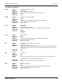
1-8. RELATED MANUALS: The following manuals contain information that may be used in conjunction with this
manual to operate, service, or calibrate this instrument.
Title
Manual
H4-1 and H4-2
Federal Supply Code for Manufacturers Cataloging Handbook
IM-275
Operating & Installation Instructions for 3200T & 3201T Series
SmartStep Programmable Attenuators
IM-276
Operating & Installation Instructions for 150T, 151T, 152T & 152T Series
SmartStep Programmable Attenuators
IM-248
Operating & Installation Instructions for 4226 & 4228 Series
SmartStep Solid-State Programmable Attenuators
1-9. ELECTROSTATIC DISCHARGE SENSITIVE: The equipment documented in this manual contains certain
Electrostatic Discharge Sensitive (ESDS) components or parts. Therefore, certain procedures/steps are identified by
the use of the symbol .
. This symbol is used in two ways:
CAUTION
All procedures and/or steps identified as must be followed exactly as written and according to
accepted ESDS device handling procedures. Failure to comply WILL RESULT in ESDS damage.
a. When the ESDS symbol is placed between a paragraph number and title
, all of that
paragraph, including all subparagraphs, is considered ESDS device handling procedure.
b. When the ESDS symbol is placed between a procedure/step number and the text
that procedure is considered an ESDS device handling procedure.
, all of
1-10. ABBREVIATIONS AND ACRONYMS: The following list contains abbreviations used throughout this manual.
Abbreviations and acronyms that are not listed conform to MIL-STD-12D.
DUT
ESDS
DIB
TBD
Device Under Test
Electrostatic Discharge Sensitive
Device Interface Bus
To Be Determined
1-11. SAFETY CONSIDERATIONS: The Attenuator Unit and all related documentation must be reviewed for
familiarization with safety markings and procedures before any operation and/or service. Refer to the SAFETY
SUMMARY located at the beginning of this manual for a summary of safety information and procedures. Following
these simple safety precautions will ensure safe operation and service of the Attenuator Unit.
1-12. POWER REQUIREMENTS: Aeroflex / Weinschel supplies a detachable power cable (P/N 068-21) to connect
an 100 to 240 Vac power source with a frequency between 50 to 60 HZ to the Attenuator Unit. To minimize shock
hazard, the instrument chassis must be connected to an electrical ground. Using the supplied three-conductor power
cable ensures that the instrument can be firmly connected to the ac power source and electrical ground (safety
ground) at a grounded power outlet. Refer to paragraph 4-2 (Initial Setup) before applying any power to the
instrument.
1-13. ENVIRONMENTAL REQUIREMENTS: This instrument performs best within its specifications when operated
within a controlled environment having an ambient temperature of 0°± 50°C, Relative Humidity of up to 95% non
condensing, and a altitude of less than 40,000 feet. Operating beyond these limits can affect the accuracy and
performance of the instrument and damage internal circuitry.
Aeroflex / Weinschel
7
Model 8311 Attenuator Unit
IM-303A
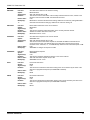
2. SPECIFICATIONS:
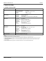
2-1. GENERAL SPECIFICATIONS:
Input Power Requirements
ac 100 to 240 Vac, 50/60 Hz, 50 Watts
Environmental
Operating Temperature
Storage Temperature:
Humidity:
Altitude:
IEEE-488 Bus(1)
Connector:
Protocols:
Indicators:
RS-232 Bus(2)
Connector:
9-pin male D
Signals: TXD, RXD, RTS, CTS, DTR, GND
Baud Rates:
2400, 9600, 19200, and 38400
Data Bits:
8
Handshaking:
None, RTS/CTS, XON/XOFF
Parity:
None, Odd, Even
Indicators:
Tx (Transmit) and Rx (Receive)
RS-422 Bus(3)
RS-485 Bus(4)
Connector:
9-pin male D
Signals: TXD+, TDX-, RXD+, RTX-, RTS+, RTS-, CTS+, CTS-,
and signal GND
Baud Rates:
2400, 9600, 19200, and 38400
Data Bits:
8
Handshaking:
None, RTS/CTS, XON/XOFF
Parity:
None, Odd, Even
Indicators:
Tx (Transmit) and Rx (Receive)
RF Characteristics(5)
See Model Configuration Table (pg 9)
0 to +50°C
67° to +167 °F (-55° to +75°C)
96%
40,000' (12,192M)
24-pin per IEEE-488.1
per IEEE-488.2
Remote (RMT), Listen (LSN), Talk (TLK), SRQ (SRQ)
NOTES:
1. GPIB/IEEE-488 model allows user-selectable addresses.
2. RS-232 can be used with standard PC serial port for short and medium distances (up to approximately 50 ft).
3. RS-422: designed for very long distance communications (4000 ft) and & optimized as a single node protocol, typically with one device
connected to a single port.
4. RS-485: designed for very long distance communications (4000 ft) & optimized for multi-drop connections that can used to create a
low cost network.
5. Refer to Individual data sheet (Appendix C) for detailed specifications on internal programmable attenuators.
Aeroflex / Weinschel
8
Model 8311 Attenuator Unit
IM-303A
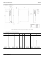
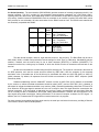
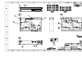
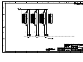
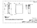
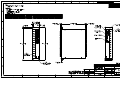
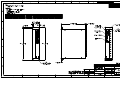
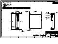
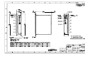
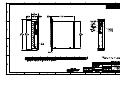
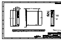
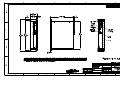
2-2. PHYSICAL DIMENSIONS:
NOTE: All dimensions are given in mm (inches) and are maximum, unless otherwise
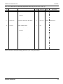
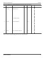
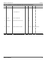
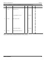
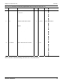
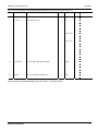
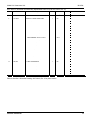
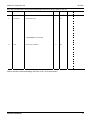
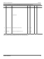
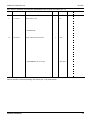
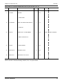
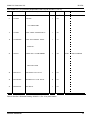
2-3. CONFIGURATIONS\RF SPECIFICATIONS:
Attenuator
Value
Frequency
Range (GHz)
Insertion Loss
SWR
No. of
Channels
Attenuator Type
Connector
Type
8311-1-6-R
63/1
dc-1.0
6.00 dB max
1.6 max
6
3250T-63
BNC/F
Rear
8311-1-6-F
63/1
dc-1.0
6.00 dB max
1.6 max
6
3250T-63
BNC/F
Front
193-7301-2
8311-38-6-F
63/1
dc-2.0
5.25 dB max
1.4 max
6
3206T-1
N/F
Front
193-7302-2
8311-38-12-T
63/1
dc-2.0
5.25 dB max
1.4 max
6
3206T-1
N/F
8311-137-6-F
63/1
dc-3.0
4.70 dB max
1.6 max
6
4226T-63
N/F
Front
193-7303-2
8311-137-6-R
63/1
dc-3.0
4.70 dB max
1.6 max
6
4226T-63
N/F
Rear
193-7303-12
8311-202-2-F
121/1
dc-18.0
5.25 dB max
1.95 max
2
150T-11, 150T-110
SMA/F
Front
193-7305-2
8311-202-3-F
8311-204-6-F
121/1
62/2
dc-18.0
dc-18.0
5.25 dB max
3.25 dB max
1.95 max
1.95 max
2
6
150T-11, 150T-110
150T-62
SMA/F
SMA/F
Front
Front
193-7305-3
193-7304-2
8311-204-6-R
62/2
dc-18.0
3.25 dB max
1.95 max
6
150T-62
SMA/F
Rear
193-7304-12
8311-352-3-R
103/1
dc-6.0
6 dB max
1.55 max
3
3408T-103
SMA/F
Front
193-7306-13
8311-352-4-R
103/1
dc-6.0
6 dB max
1.55 max
4
3408T-103
SMA/F
Front
193-7306-14
8311-352-6-F
103/1
dc-6.0
6 dB max
1.55 max
6
3408T-103
SMA/F
Front
193-7306-2
8311-352-9-T
103/1
dc-6.0
6 dB max
1.55 max
9
3408T-103
SMA/F
Front
193-7306-9
Model No
Aeroflex / Weinschel
Connector
Location
Drawing Number
193-7301-1
Front-Rear 193-7302-8
9
Model 8311 Attenuator Unit
IM-303A
3. INSTALLATION:
3-1. RACKMOUNTING: Standard 8311 Attenuator Units are shipped with four plastic feet mounted to the bottom
cover, this allows the user to place the instrument on any bench or to stack the with other Weinschel instruments. The
Model 8311 can also be rack mounted as a single unit using Rack Mounting Kit (P/N 193-8033-1). This kit allows the
Model 8311 to be mounted in any rack or cabinet that is designed according to EIA RS-310 or MIL-STD-189.
3-2. INITIAL SETUP: The following initial setup procedures should be performed prior to operating the 8311 Unit.
a. Perform inspection paragraph 1-5 prior to connecting the 8311 Series to any power source.
b. Check that the external power source outputs to the 8311 Series are in accordance with
Section 2, Specifications.
c.
Install the 8311 Series into a cabinet or rack, if desired.
d. Using the supplied power cord connect the 8311 Series to the external power source.
e. Setup the IEEE-488 bus address or RS-232/422 Communications options for your application using
paragraph 4-2.6. If using the RS-422 serial configure the selectable signal pair terminations using
paragraph 5-3.
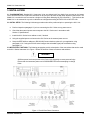
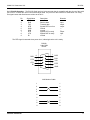
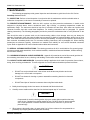
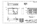
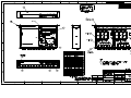
3-3 INPUT/OUTPUT OPTIONS: The following paragraphs provide a description of the connections that can be made
to the 8311 Series Attenuator Unit. Figure 1 shows the location of these connectors and switches.
WARNING
Sufficient power levels are present at the Power Input Assembly to cause personal injury.
Ensure that the instrument power cord is DISCONNECTED before attempting to change
fuses.
Figure 1. Front & Rear Panel Connectors
Aeroflex / Weinschel
10
Model 8311 Attenuator Unit
IM-303A
3-3.1 POWER ENTRY MODULE ASSEMBLY: The Power Entry Module Assembly located on the rear panel contains
a three-prong ac power input connector and a fuse drawer assembly (Figure 1). The Fuse Drawer Assembly
contains the line voltage fuse (Weinschel P/N 052-1-1.5). The Model 8311 uses a T 1.5A, 250 Vac fuse which is 5 x
20 mm in size. Refer to paragraph 8-4.1 for replacement of the fuse.
The AC Power Connector, located on the left side of XF1 (Figure 1), is a plug-type, prong insert connector with three
conductors for connection of the power cord (P/N 068-21) to the Power Supply Assembly located within the Attenuator
Unit. This connector also grounds the chassis of the Attenuator Unit when the the ac power cord is connected to a
grounded wall outlet. If necessary, use a three prong to two prong adapter and connect the adapter’s ground lead to
the outlet plate retaining screw.
The Power ON/OFF Switch is located on the rear panel and in part of the Power Entry Module Assembly. Placing the
POWER ON/OFF switch in the ON position applies power to the instrument.
CAUTION
When applying an RF signal to the RF INPUT connector, DO NOT exceed the maximum allowable
power level specifications of the Model 8311.
3-3.2. CHANNEL PORT CONNECTORS: A typical 8311 Series Attenuator Unit contains 12 standard D holes
on the front and rear panel allowing for single or multichannel configurations. Standard Model 8311’s are
supplied with two PLANAR CROWN® Type N connectors that can be mounted on the front or rear panel.
These connectors provide a input and output port where various types of RF signals can be applied to the
devices internally mounted in the Model 8311 (Connector location specified by customer when ordering).
Some special configurations could contain Aeroflex / Weinschel’s Model 1568 SMA Panel Adapters or other
types of crowns (see accessories for other types).
NOTE
The use of the PLANAR CROWN® connectors provide the user with easy exchange of connector
types, which eliminates the need for adapters and other devices that would create additional insertion
loss. This type of connector also provides quick removal and replacement of defective connectors.
For more information about the PLANAR CROWN® connectors contact the Sales Department at
Aeroflex / Weinschel, Inc.
Aeroflex / Weinschel
11
Model 8311 Attenuator Unit
IM-303A
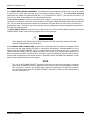
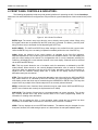
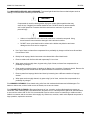
4. FRONT PANEL CONTROLS & INDICATORS:
The following paragraphs provide setup and general guidelines for operating the 8311 Series SmartStep
Attenuator Unit and its different bus configurations. Also provided is a general description of the internal circuitry of the
8311.
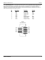
Figure 2. 8311 Series Front Panel
ENTRY keys: The numeric entry keys allow the user to directly enter numeric values. When using
the keypad, values are not updated until the ENT (enter) key is pressed. The Minus (-) and CE (clear
entry) functions may be accessed via first depressing the SHIFT key.
INCR & DECR : The INCR and DECR keys allow settings to be scrolled from their current value.
Unlike the ENTRY keys, the new setting is updated immediately without the use of the ENT key.
CHAN: Allows the selection of the current channel, as indicated by the CH1-CH4 indicators.
Repeated depressions of the CHAN key will select the next available channel. The main display will
show the current setting of the channel. For configurations with 5 or more channnels, selecting the
CHAN key will display the current selected channel in the main display. Channels are then selected
via the INCR and DECR keys.
REL: This key control allows the use of a relative mode for attenuators, as indicated by the REL
mode indicator. When turned on, the currently displayed attenuation value is used as a reference
value from which the attenuation may be set. In this mode, attenuation values may be positive or
negative from the reference setting. When REL is turned off, the display returns to the actual
attenuation setting for the channel.
STEP: This key allows the user to change the attenuation step size used by the INCR and DECR
keys. When turned on, as, indicated by the STEP indicator, the current step size is displayed in the
main display, and a new value may be entered using the INCR/DECR or ENTRY keys. The step size
may be set to any multiple of the intrinsic step size for the currently selected channel.
MENU: Invokes the menu functions. Menu selections may be made via the INCR and DECR keys.
(NOTE: menu functions are currently not implemented as of 3/8/99)
AUX1/AUX2: The function of these keys is user-programmable via remote operation. They invoke
any currently defined AUX1 and AUX2 macros. Refer to the macro programming section for
information on creating macro definitions.
LOCAL: This key places the 8311 in local operation mode, unless the key function has been
overridden via an IEEE-488.2 local lockout or execution of the LOCKOUT command.
ADDR: This key displays the current IEEE-488.2 address. The address may be changed from the
front-panel, however, the initial setting at power on is derived from the rear-panel address switch.
Aeroflex / Weinschel
12
Model 8311 Attenuator Unit
IM-303A
5. REMOTE OPERATION:
The following paragraphs provide setup and general guidelines for operating the Model 8311 using an
external controller.
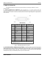
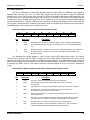
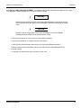
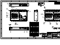
5-1. IEEE-488 INTERFACE BUS CONNECTOR: Joining the Model 8311-1 to a system controller requires the
connection of IEEE-488 control bus cable to the IEEE-488 INTERFACE BUS connector located on the rear panel.
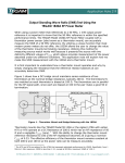
Figure 3 shows the connector’s contact pin numbering scheme and lists the signal designator for signal present at
each contact pin.
PIN No.
SIGNAL LINE
PIN No.
SIGNAL LINE
1
DIO 1
13
DIO 5
2
DIO 2
14
DIO 6
3
DIO 3
15
DIO 7
4
DIO 4
16
DIO 8
5
EOI (24)**
17
REN (24)**
6
DAV
18
GND (6)*
7
NRFD
19
GND (7)*
8
NDAC
20
GND (8)*
9
IFC
21
GND (9)*
10
SRQ
22
GND (10)*
11
ATN
23
GND (11)*
12
SHIELD
24
GND, LOGIC
* GND (N) refer to the signal ground return of the referenced pin.
** Return pin on pin 24.
Figure 3. IEEE-488 Interface Bus Pin Locations
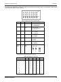
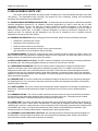
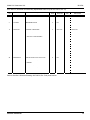
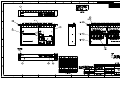
5-2. GPIB ADDRESS/SERIAL COMMUNICATIONS SETTINGS: The GPIB Bus Address and Serial Communications
options are programmed via an internal 8 position DIP switch SW1 which is located on the rear panel. The switch is
shared between the two functions, with SW1-1 controlling the selection. When SW1-1 is OFF, the remaining switches
set the GPIB bus address. Likewise, when SW1-1 is ON, the switches are used to select the various serial options,
including baud rate, parity, and handshaking. Refer to Figure 4 for switch location.
Aeroflex / Weinschel
13
Model 8311 Attenuator Unit
IM-303A
To configure the IEEE-488 bus address or serial communications parameters, select the appropriate switch setting
using the tables located in below (Figure 4).
GPIB
SW1
Serial
Serial Parameters
SP
1
SP
Mode Select
On = Serial parameters
Off = GPIB address
---
2
Echo
Echo Echo Enable
On = Echo received data
Off = No echo
---
3
HndshkSel
Handshaking Select
On = RTS/CTS
Off = XON/XOFF
A4 (16)
4
HndshkEna
Handshake Enable
On = Enabled
Off = Disabled
A3 (8)
5
ParitySel
Parity Select
On = Odd
Off = Even
A2 (4)
6
ParityEna
Parity Enable
On = Enabled
Off = Disabled
A1 (2)
A0 (1)
7
8
BR1
BR2
BaudRate Select (see below)
BaudRate Select
BR1
BR0
RATE
0
0
1
1
0
1
0
1
2400
9600
19200
38400
Note: The GPIB Bus address is selectable from 0 to 30 via the rear
panel dip switch. This switch is factory set to 10.
IEEE-488 Address Truth Table
Switch Number
Decimal Weight
4
16
5
8
6
4
7
2
8
1
Address:
0
1
2
3
4
5
6
7
8
9
10
20
30
0
0
0
0
0
0
0
0
0
0
0
1
1
0
0
0
0
0
0
0
0
1
1
1
0
1
0
0
0
0
1
1
1
1
0
0
0
1
1
0
0
1
1
0
0
1
1
0
0
1
0
1
0
1
0
1
0
1
0
1
0
1
0
0
0
Figure 4. Internal Dip Switch
Aeroflex / Weinschel
14
Model 8311 Attenuator Unit
IM-303A
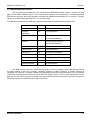
5-3. IEEE-488 (GPIB) Bus Operation
The internal functions of Model 8311 are controlled via an IEEE-488 bus and an external controller. The front
panel LSN and RMT indicators (Figure 2) are used as status indicators for the Model 8311 SmartStep Interface’s
IEEE-488 bus operation. During bus operation a flashing LSN indicates that the Model 8311 is receiving. The RMT
indicator is illuminated when the Model 8311 is in the remote state.
The table below summarizes the IEEE-488.1 interface functions that are implemented by the Model 8311.
Interface Function
Subset
Description
Source Handshake
SH1
Fully implemented
Acceptor
Handshake
AH1
Fully implemented
Talker
T6
All basic Talker functions
No extended addressing
Listener
L4
All basic Listener functions.
No extended addressing
Service Request
SR1
Fully implemented
Remote/Local
RL1
Fully implemented
Parallel Poll
PP0
No Parallel Poll Capability
Device Clear
DC1
Fully implemented
Device Trigger
DT0
No Trigger
Controller
C0
No Controller Functions
Electrical Interface
E2
All tri-state drivers
The GPIB interface of the 8311 is IEEE-488.2 compliant. The 8311 recognizes instructions and data sent via
the GPIB interface in the form of program messages comprised of ASCII characters. A program message is
comprised of a sequence of program message units separated by semicolons and terminated by a line terminator
(LINE END). A line terminator takes the form of an ASCII LF character (0AH), or an EOI signal asserted with the last
data byte, or both. The 8311 program message units may be divided into two syntax groups: commands and queries.
Refer to the section on command syntax for more information.
Aeroflex / Weinschel
15
Model 8311 Attenuator Unit
IM-303A
5-4. Serial Operation: The serial interface (RS232/RS422) provides a means of remotely programming the 8311 via
external computer. The 8311 provides for user-selectable communications parameters via a DIP switch (SW1),
including baud rate, data format, and handshaking method. LED indicators are provided for transmit (TX) and receive
(RX) activity. Selection between RS232/RS422 mode is controlled via an internal 4 position DIP switch SW2, which
also provides for user-selectable 120 ohm terminations for the RS422 receiver lines. The RS422 mode transceivers
are electrically compatible with RS485.
SW2
RS232
RS422
RS485
User
Select
1
OFF
2
OFF
User
Select
3
4
OFF
ON
ON
OFF
Description
CTS Termination
On = Termination
Off = No Termination
RXD Termination
On = Termination
Off = No Termination
RI/RTS Select
Serial Mode
On = RS232
Off = RS422
The data format includes a start bit, eight data bits, and one stop bit (N81). The Baud Rate may be set to
2400, 9600, 19200, or 34800. Parity selections include settings for None, Even, or Odd parity. Handshaking may be
enabled, if desired, and the method may be set to either hardware (RTS/CTS) or software (XON/XOFF). For
interactive terminal use, echoing may be enabled, in which the 8210A will echo all characters received back to the
terminal.
All data and commands are encoded using the ASCII character set. The syntax for commands is the same as
for GPIB operation, and uses the syntax structure defined by IEEE 488.2, with the exception of the command
termination rules. Commands sent to the 8210A may be terminated with either an ASCII CR (0x0D) or ASCII LF
(0x0A) character. By default, all responses from the 8210A are terminated in an ASCII CR/LF sequence (0x0D
followed by 0x0A).
Software handshaking uses the XON/XOFF scheme in which an ASCII DC3 (0x13) character is transmitted
by the receiver to indicate that data transmission should be halted (XOFF), and an ASCII DC1 (0x11) character is
transmitted to indicate that data transmission may continue (XON). Hardware handshaking utilizes the RTS and CTS
lines. When the RTS output signal is asserted true, the unit is ready for data. This signal should be connected to the
external computer's CTS input signal, so that when the receiver is ready, the transmitter may send data. When the
unit is not ready for data, it unasserts the RTS signal, halting data transmission. Likewise, the unit monitors the CTS
input signal during data transmission, halting transmission if the external computer unasserts it's RTS signal. In
addition, the 8311 unasserts the RTS signal while command execution is in progress.
For those systems incorporating local front panel controls, the serial port can lockout local users, providing a Remote/
Local function similar to that of GPIB operation.
Aeroflex / Weinschel
16
Model 8311 Attenuator Unit
IM-303A
5-4.1. RS-232 Operation: The RS-232 Serial port is a 9-pin connector that is compatible with the pin-out of the serial
port on a PC. It allows the use of a null-modem style cable. The pin-out for the connector is show below. For clarity,
the signal names and directions are relative to the 8311.
Pin
1
2
3
4
5
6
7
8
9
Signal Name
DCD
RxD
TxD
DTR
GND
DSR
RTS
CTS
RI
Description
unused
Receive data
Transmit data
Signals DTE is on-line
Ground
unused
Signals DTE is ready
Signals DCE is ready
unused
Direction
--input
output
output
----output
input
---
The DTR signal is asserted when power is on, indicating that the unit is ready.
RS232
9-pin DB9
Pinout
DSR
RTS
CTS
RI
6
7
8
9
1
2
3
4
5
DCD
RxD
TxD
DTR
GND
Null Modem Cable
Aeroflex / Weinschel
1
1
2
2
3
3
4
4
5
5
6
6
7
7
8
8
9
9
17
Model 8311 Attenuator Unit
IM-303A
5-4.2. RS-422/485 Operation: The RS-422/RS-485 Serial mode is useful in applications requiring long cable lengths
(up to 5000 ft at 9600 baud), or in electrically noisy environments. All communication parameters available for the
RS232 port are also available under RS-422 operation (baud rate, handshaking, etc). Full Duplex operation is
supported. The RS-422 port utilizes a 9-pin connector. The pin-out for the connector is show below. For clarity, the
signal names and directions are relative to the 8311.
Pin
1
2
3
4
5
6
7
8
9
Signal Name
RxD+
RxDTxDTxD+
GND
CTS+
RTSCTSRTS+
Description
Receive data
Receive data
Transmit data
Transmit data
Ground
Clear To Send
Request To Send
Clear To Send
Request To Send
Direction
input
input
output
output
--input
output
input
output
RS422
9-pin DB9 Pinout
CTS+
RTS CTS RTS+
Aeroflex / Weinschel
6
7
8
9
1
2
3
4
5
RXD+
RXDTXDTXD+
GND
18
Model 8311 Attenuator Unit
IM-303A
5-5. Status Reporting
The 8311A implements the 488.2 Status Reporting Structure, which utilizes the IEEE488.1 status byte with
additional data structures and rules. The Status Byte Register can be read with either a serial poll (IEEE-488
operation only) or the *STB? common query command. The Service Request Enable Register (SRE) allows the user
to select which bits in the Status Byte Register may cause service requests. A bit value of one indicates that the
corresponding event is enabled, while a bit value of zero disables an event. The Service Request Enable Register
may be accessed with the *SRE and *SRE? common commands. The Status Byte Register may be cleared with the
*CLS common command, with the exception of the MAV bit, which is controlled by the operation of the Output Queue.
The SRE Register is set to 0 at power-on, disabling all events.
Status Byte Register/ Service Request Enable Register Formats
D7
D6
RQS
D5
ESB
D4
MAV
D3
D2
EEQ
D1
D0
Bit
Mnemonic
6
RQS
Request Service: This bit, if set, indicates that the device is asserting the SRQ signal.
5
ESB
Event Status Bit: This bit is true when an enabled event in the Event Status Register is
true.
4
MAV
Message Available: This bit is true when there is valid data available in the output queue.
2
EEQ
Error/Event Queue: This bit is true when there is Error/Event data available in the
Error/Event queue.
Description
The Standard Event Status Register is used to report various IEEE 488.2-defined events. The register
contents may be accessed with the *ESR? command. An Event Status Enable Register allows the user to select
which bits in the ESR that will be reflected in the ESB summary message bit of the Status Byte Register. The Event
Status Enable Register may be accessed with the *ESE and *ESE? common commands. The Event Status Register
is cleared by an *ESR? query or *CLS common command. The ESE Register is set to 0 at power-on, disabling all
events.
Standard Event Status Register/ Standard Event Status Enable Register Formats
D7
ON
D6
URQ
D5
CME
D4
EXE
D3
DDE
D2
QYE
D1
RQC
D0
OPC
Bit
Mnemonic
7
PON
Power On: This bit indicates that the device has powered-on
6
URQ
User Request: This event bit indicates that a local control is causing a
User Request
5
CME
Command Error: The parser has detected a syntax error in the current command.
4
EXE
Execution Error: The command could not be properly executed due to
an illegal input range or other inconsistent data.
3
DDE
Device Dependent Error: A command could not properly complete due to some
device specific error
2
QYE
Query Error: This bit indicates that either an attempt has been made to read data
when there was none present, or that data in the Output Queue has been lost
1
RQC
Request Control: The device is requesting control (not implemented)
0
OPC
Operation Complete: This bit is generated in response to an *OPC command. It
indicates that the ITS 2000 has completed all pending operations.
Aeroflex / Weinschel
Description
19
Model 8311 Attenuator Unit
IM-303A
The Status Reporting Registers may be used for serial communications, with certain limitations. The Status
Byte Register can only be read via the *STB? query command, as the comm port does not provide for a serial poll
operation. Also, as data in the Output Queue is sent automatically during serial operation, the MAV message available
bit in the STB serves no purpose.
5-6. GENERAL SYNTAX STRUCTURE: The following paragraphs outline the general syntax and command structure
for the Model 8311. This structure is common to all bus flavors of the Model 8311.
NOTE
In the descriptions that follow, the term whitespace is used to define a sequence
of one or more combinations of ASCII Space (20h), Carriage return (0Dh), or
Tab (09h) characters.
5-6.1 SYNTAX OF QUERIES: A query message unit is made up of a query header ending in an ASCII question mark
character ’?’ (3FH), followed by optional whitespace, and ended by a program message terminator. To form a multiple
query, separate the individual program message units with a semicolon.
Examples :
"ATTN?"
"ASSIGN?"
b. Multiple Query Commands:
"ATTN?; ASSIGN?"
5-6.2 SYNTAX OF COMMANDS: A command message unit is made up of a command header, optionally followed by
an argument and units, and ended by a program message terminator. If multiple commands are made on the same
program line, separate the individual command messages with a semicolon.
Arguments - The 8311 supports a variety of argument types that can be used in program commands.
These types are:
Character Program Data
Integer Numeric Program Data
Real Numeric Program Data
Each data type has its own rules of syntax. The following paragraphs provide the syntax rules for each of the
argument types listed above.
Character Program Data-This data type is comprised of the set of printable ASCII characters (excluding those
used as delimiters). Character program data represents alpha or alphanumeric strings. The use of alpha
characters is case-insensitive. If the first character of the string is not an alpha character, then the string must be
delimited with either the ASCII single-quote (’) or double-quote (") character in order to distinguish the string from
a numeric data type.
Examples:
ATTEN1
ON
"150T"
Integer Numeric Program Data-This data type is used to represent integer, binary, or hexidecimal numeric
information, all of which may be used interchangeably. Integer data is comprised of the numeric digits ’0’-’9’,
binary data is comprised of the digits ’0’ and ’1’ preceded by the characters ’#B’, and hexidecimal data is
comprised of the digits ’0’-’9’, and the letters ’A’-’F’, preceded by the characters ’#H’ or the C language style
prefix ’0x’.
Examples:
Aeroflex / Weinschel
123 (integer)
#H55 (hex)
0xAA (hex)
#B1010 (binary)
20
Model 8311 Attenuator Unit
IM-303A
Real Numeric Program Data-This data type includes decimal numbers containing a sign, decimal point, and/or
an exponent. The format is as follows: [sign]digits[.[digits][E[sign]digits]]
Examples:
2
2.5
-35.25E+2
In the command descriptions that follow, argument types are also described using the following additional
conventions to indicate the relative size of the parameter:
byte
- used to indicate an 8-bit unsigned integer
word
- used to indicate a 16-bit unsigned integer
int8
- 8-bit integer
int16
- 16-bit integer
int32
- 32-bit integer
string
- character data, including the max number of characters allowable.
(i.e., string8 has a max of 8 chars)
5-6.3 OUTPUT DATA FORMAT: Output data from the Model 8311 consists of a series of ASCII digits and message
strings, terminated with an ASCII Line-Feed character (0AH), in response to a program message that contains one or
more query commands. In the case of multiple query commands in the same program message, the data resulting
from each of the individual message units will be separated by an ASCII comma (2CH) character.
5-6.4 NOTATIONAL CONVENTION.
[]
Brackets indicate optional arguments or parameters.
{}
One and only one of the enclosed entries must be selected unless the field is also
surrounded by brackets, in which case it is optional.
...
Ellipses indicate that the preceding argument or parameter may be repeated.
[,...]
The preceding item may be repeated, but each repetition must be separated by a comma.
Aeroflex / Weinschel
21
Model 8311 Attenuator Unit
IM-303A
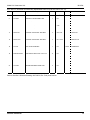
5-8. 488.2 COMMON COMMANDS
*CLS
Function:
Syntax:
Argument(s):
Remarks:
Return Value:
Example(s):
Clears the Status Byte and Event Status Registers.
*CLS
none
This function is used to clear the Status Byte and the Event Status Registers.
none
*CLS
*ESE
Function:
Syntax:
Argument(s):
Remarks:
Return Value:
Example(s):
Sets the Event Status Enable Register.
*ESE mask
mask integer bitmask
This function is used to set the Event Status Enable Register to the value specified by mask.
none
*ESE 255
*ESE?
Function:
Syntax:
Argument(s):
Remarks:
Return Value:
Example(s):
Reads the Event Status Enable Register.
*ESE?
none
This function is used to read the Event Status Enable Register.
mask integer register mask
*ESE? returns the following ’255’
*ESR?
Function:
Syntax:
Argument(s):
Remarks:
Return Value:
Example(s):
Reads the Event Status Register
*ESR?
none
This function is used to read the Event Status Register. Reading the register clears it.
reg integer register
*ESR? returns the following ’128’
*SRE
Function:
Syntax:
Argument(s):
Remarks:
Return Value:
Example(s):
Sets the Status Byte Enable Register
*SRE mask
mask integer bitmask
This function is used to set the Status Byte Enable Register to the value specified by mask.
none
*SRE 255
*SRE?
Function:
Syntax:
Argument(s):
Remarks:
Return Value:
Example(s):
Reads the Status Byte Enable Register.
*SRE?
none
This function is used to read the Status Byte Enable Register.
mask integer register mask
*SRE? returns the following ’255’
*STB?
Function:
Syntax:
Argument(s):
Remarks:
Return Value:
Example(s):
Reads the Status Byte Register.
*STB?
none
This function is used to read the Status Byte Register.
reg integer register
*STB? returns the following ’96’
*IDN?
Function:
Syntax:
Argument(s):
Remarks:
Reads the system identification information.
*IDN?
none
This function is used to read the system identification information, which is a string consisting of the
following data: manufacturer, model, serial number, and firmware version.
mfg integer count of devices
*IDN? returns the following ’Weinschel,8311 Series, 123, 1.00A’
Return Value:
Example(s):
Aeroflex / Weinschel
22
Model 8311 Attenuator Unit
IM-303A
*RST
Function:
Syntax:
Argument(s):
Remarks:
Return Value:
Example(s):
Performs a device reset.
*RST
none
This function is used to reset the device.
none
*RST
*OPC
Function:
Syntax:
Argument(s):
Remarks:
Operation complete service request.
*OPC
none
This function generates the Operation Complete message (OPC) in the Standard Event Status
Register when all pending device operations have finished.
none
*OPC
Return Value:
Example(s):
*OPC?
Function:
Syntax:
Argument(s):
Remarks:
Return Value:
Example(s):
*WAI
Function:
Syntax:
Argument(s):
Remarks:
Return Value:
Example(s):
Aeroflex / Weinschel
Operation complete query
*OPC?
none
This function loads a ’1’ into the output queue when the Program Message Unit is executed. Its
primary use is to provide an indication of command completion by including the command as the
last one in a series of commands.
1 integer command completed
SAVE ASSIGN; *OPC? returns a ’1’ when the SAVE ASSIGN command completes.
Wait To Continue
*WAI
none
This function prevents the8311 Series from executing any further commands or queries until there
are no pending operations. The 8311 Series executes all commands sequentially, and does not
allow overlapping commands.
none
*WAI
23
Model 8311 Attenuator Unit
IM-303A
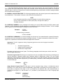
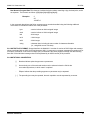
5-9. GENERAL COMMANDS:
CHAN
Function:
Syntax:
Argument(s):
Remarks:
Return Value:
Example(s):
Selects the currently active channel
CHAN chnum
chnum integer channel number
This function is used to select the currently active channel.
none
CHAN 1
CHAN?
Function:
Syntax:
Argument(s):
Remarks:
Return Value:
Example(s):
Reads the current channel number
CHAN?
none
This function is used to read the currently active channel number.
chnum integer current channel number
CHAN? returns ’1’
ATTN
Function:
Syntax:
Argument(s):
Remarks:
Return Value:
Example(s):
Set attenuation
ATTN atten
atten real desired value, in dB
This function sets the attenuation of the currently selected channel to atten.
none
ATTN 63
ATTN 12.25
ATTN 45.0
ATTN?
Function:
Syntax:
Argument(s):
Remarks:
Return Value:
Example(s):
Read attenuation
ATTN?
none
This function reads the attenuation of the currently selected channel.
atten real attenuation value, in dB
ATTN? returns ’63.00’
REL
Function:
Syntax:
Argument(s):
Remarks:
Sets relative display mode for the current channel
REL mode
mode integer relative mode on/off
This function is used to set the relative display mode of operation for the current channel.
A value of 0 for the parameter mode will turn relative mode off, while a value of 1 will turn
relative mode on.
none
REL 1
Return Value:
Example(s):
REF
REF?
Function:
Syntax:
Argument(s):
Remarks:
setting.
Sets reference
REF
none
This function sets the reference value for the active channel to the current attenuation
Return Value:
Example(s):
This command is used for the REL and RELATTN functions.
none
REF; REL 1 sets the reference, and turns on relative mode
Function:
Syntax:
Argument(s):
Remarks:
Return Value:
Example(s):
Read reference setting
REF?
none
This function reads the reference setting of the currently selected channel.
refatten real reference attenuation value, in dB
REF? returns ’30.00’
Aeroflex / Weinschel
24
Model 8311 Attenuator Unit
IM-303A
Return Value:
Example(s):
10
Sets attenuation relative to the reference setting
RELATTN atten
atten real desired value, in dB
This function sets the attenuation of the currently selected channel to atten, relative to the
reference value set when the REL command was executed.
none
RELATTN 10 increases the attenuation setting 10dB from the reference setting RELATTN decreases the attenuation setting by 10dB from the reference setting 15.
RELATTN?
Function:
Syntax:
Argument(s):
Remarks:
Return Value:
Example(s):
Read relative attenuation of the current channel
RELATTN?
none
This function reads the relative attenuation of the currently selected channel.
relatten real relative attenuation value, in dB
RELATTN? returns ’-10.00’
STEPSIZE
Function:
Syntax:
Argument(s):
Remarks:
Return Value:
Example(s):
Sets attenuation stepsize for the current channel
STEPSIZE atten
atten real desired stepsize value, in dB
This function sets the attenuation stepsize for the INCR and DECR commands for the
current channel to atten. The default value of the attenuator’s stepsize is the intrinsic
resolution of the attenuator, i.e., a 127dB/1dB step attenuator has a default stepsize of 1dB.
none
STEPSIZE 10 changes the stepsize to 10dB
STEPSIZE?
Function:
Syntax:
Argument(s):
Remarks:
Return Value:
Example(s):
Read attenuation stepsize
STEPSIZE?
none
This function reads the attenuation stepsize of the current channel.
atten real attenuation stepsize value, in dB
STEPSIZE? returns ’10.00’
INCR
Function:
Syntax:
Argument(s):
Remarks:
Increments attenuation
INCR
none
This function increments the attenuation setting of the current channel by the value of the
attenuator’s programmed stepsize (see STEPSIZE command).
none
INCR
RELATTN
Function:
Syntax:
Argument(s):
Remarks:
Return Value:
Example(s):
DECR
Function:
Syntax:
Argument(s):
Remarks:
Return Value:
Example(s):
Aeroflex / Weinschel
Decrements attenuation
INCR
none
This function decrements the attenuation setting of the current channel by the value of the
attenuator’s programmed stepsize (see STEPSIZE command).
none
DECR
25
Model 8311 Attenuator Unit
IM-303A
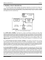
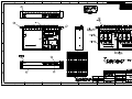
6. GENERAL CIRCUIT DESCRIPTION:
This section contains general descriptions and systematic explanation of the Model 8311’s design and
internal circuitry. Standard 8311 Series SmartStep Attenuator Units contain internal circuitry to control a variety of
Aeroflex / Weinschel programmable attenuators (3200T, 150T, and 4200 Series) via front panel controls or standard
communications interfaces including GPIB (IEEE-488) and RS-232/RS-422 /RS485. Figure 5 provides a simplified
block diagram of the 8311’s internal circuitry.
Figure 5. 8311 Series Simplifed Block Diagram
6-1. POWER SUPPLY ASSEMBLY: The Model 8311 contains a high-efficiency switching type Power Supply
Assembly (A3) which will operate with a 100 to 240 Vac input power source. The input power source is routed thru the
Power Entry Module Assembly (XF1) before being applied to the Power Supply Assembly. The Power Entry Module
Assembly allows the user to select between the two operational voltage ranges that can be accepted by the Power
Supply Assembly. This Switching Power Supply provides the Model 8311 with +15 ±0.75 V @ 3.3 A outputs. These
outputs are then routed to the SmartStep Interface Assembly for distribution to the other assemblies located in the
Model 8311. Drawing 193-8102 & 193-8114 shows the actual power distribution for all assemblies and modules
located in the 8311.
6-2. STATUS DISPLAYS AND SWITCH CONTROL ASSEMBLY. This assembly located behind the front panel
contains a group of LED’s that indicates the status of bus operation and channel/port selection . The Switch/LED
Status PCB Assembly contains control switches which are used to set the GPIB address information, selected desired
port/channel, select the mode of operation (Local or Remote) and manually control and enter parameters for devices
installed in the Model 8311. These control switches operate in a toggle fashion, i.e., push for ON and push for OFF.
Refer to Section 5 for an operational description of each LED and switch located on the front panel.
6-3. SmartStep INTERFACE ASSEMBLY: This assembly is responsible for programming and control of the Driver
PCB Assembly, GPIB bus operation, and front panel Switch/LED control. The Smartstep Interface Assembly provides
a high-level interface from a standard communications interface including GPIB (IEEE-488) and RS-232/RS422/RS485, to the 8311 SmartStep’s serial Driver Interface Bus. The Device Interface Bus (DIB) is a system for
connecting a number of relatively low-speed I/O devices to a host, providing a simple, uniform, and inexpensive way
to control a variety of devices via a single port. The DIB is based on the two-wire I2C serial bus and several software
protocol layers that allow the Smartstep Interface Assembly to address the internal devices, with serial data rates of
up to 100 KHz. The DIB may also be used to supply DC power to other devices that may be installed in custom
applications, resulting in a simple, low-cost interconnection system.
Aeroflex / Weinschel
26
Model 8311 Attenuator Unit
IM-303A
6-4. RF SECTION: Most Standard 8311 Series are single channel configurations where RF signal is routed through
either the front or rear mounted Ports A & B connector (Ports A-A if the RF is routed front to rear) to a single or
multiple Weinschel programmable attenuators (3200T, 150T, or 4200 Series) thus creating CH1 (Channel 1). Note
that when a Port is in use the Port indicator will be illuminated. Dual channel units typically use Ports A and B for CH1
and Ports C and D for CH2 (Ports A-A if the RF is routed front to rear for CH1 and Ports B-B for CH2). Multi-channel
(3-4) units are generally routed front to rear and configured as follows:
CH1 Port A (Front) to Port A (Rear)
CH2 Port B (Front) to Port B (Rear)
CH3 Port C (Front) to Port C (Rear)
CH4 Port D (Front) to Port D (Rear)
For specialized configurations refer to supplemental information in the front of this manual for details.
Typically Aeroflex / Weinschel programmables are bi-directional and the RF signal can be applied to either
Port connector. Refer to the individual data sheets located in the Appendix C for detailed and specific specifications
pertaining to the internal mounted attenuators. Refer to the replaceable parts list for actual programmable attenuator
part/model number.
Special configurations exist where the RF section is designed to specific customer requirements that contain
signal programmable attenuators with custom attenuation ranges and step sizes to multiple programmables used inconjuction with other coaxial devices such as switches, power combiners, directional couplers, and filters creating
single or multi-channel subsystems. All specialized 8311 series units will contain a supplement located in the front of
this manual that outlines detailed configuration, operation and parts list for these Attenuator Units.
Aeroflex / Weinschel
27
Model 8311 Attenuator Unit
IM-303A
7. MAINTENANCE:
The following paragraphs provide general inspection and maintenance guide lines for the 8311 Series
SmartStep Attenuator Units.
7-1. INSPECTION: Perform a visual inspection in conjunction with the maintenance activities schedule when a
malfunction is suspected, or whenever an assembly is removed or replaced.
7-2. PREVENTIVE MAINTENANCE: While the 8311 requires very little preventive maintenance, it should not be
subjected to physical abuse, severe mechanical shock, high humidity, or operating temperatures outside the
specification range. The instrument should be kept free of excessive dirt and dust, since these can interfere with
connector functions and with normal heat dissipation. For cleaning instructions refer to paragraph 7-3 (special
cleaning instructions). The following paragraphs provide the preventive maintenance that is to be performed on the
Unit.
Care should be taken to prevent strain on the interconnecting cables, since damage here may not always be
apparent. Occasionally check the external cables and connectors for signs of cracked insulation and/or bent or worn
pins. Tests show that connectors must be clean for accuracy and stability. This requires an inspection and cleaning of
each connector immediately before use. For connector cleaning instructions, refer to paragraph 4-3. When cleaning
precautions are observed regularly, connectors can maintain their stability for over several thousand connection
cycles. Refer to Appendix A for more information about cables and connectors.
7-3. SPECIAL CLEANING INSTRUCTIONS: The cleaning procedures for 8311 are divided into five general groups:
microwave coaxial cable assemblies, circuit card and modules; machined surfaces and hardware, chassis cleaning,
and connector cleaning.
7-3.1. MICROWAVE COAXIAL CABLE ASSEMBLIES: Appendix A (located at the end of this manual) provides all
the necessary procedures for care, cleaning, and handling of microwave coaxial cable assemblies.
7-3.2 CIRCUIT CARDS AND MODULES: A protective coating is applied to circuit cards for protection from moisture,
arcing, short-circuiting, and abrasion. To remove light dirt from circuit cards and modules proceed as follows:
CAUTION
DO NOT use a nylon bristle brush in the solvent as the bristles may dissolve and cause
damage to the circuit card or component.
DO NOT use ultrasonic cleaning on parts or assemblies containing electrical or electronic
components.
DO NOT bend pins of electrical connectors when using fiber-bristle brush.
a. Briskly brush isopropyl alcohol onto area to be cleaned with fiber-bristle brush.
b. Carefully remove residue with a clean lint-free cloth and repeat step "a" as a rinse.
WARNING
Compressed air used for cleaning and/or drying can create airborne particles that may
enter the eye. Goggles/ face-shields should be worn. DO NOT direct air stream towards
self or other personnel. Pressure should be restricted to a maximum 15 psi to avoid
personal injury.
c.
When parts are thoroughly clean, dry parts using 5 psi of clean moisture free compressed air or
preferably dry nitrogen (pressurized spray will work well).
Aeroflex / Weinschel
28
Model 8311 Attenuator Unit
IM-303A
7-3.3 MACHINED SURFACES AND HARDWARE: To remove light dirt and dust from mechanical parts such as
castings, covers and other hardware proceed as follows:
WARNING
Compressed air used for cleaning and/or drying can create airborne particles that may
enter the eye. Goggles/ face-shields should be worn. DO NOT direct air stream towards
self or other personnel. Pressure should be restricted to a maximum 15 psi to avoid
personal injury.
CAUTION
Under no circumstances use a wire brush, steel wool, or abrasive compound. Using
these items will cause extensive damage to the instrument's surface.
DO NOT use a nylon bristle brush in solvent as the bristles may dissolve and cause
damage to the circuit card or component.
a. Use 5 psi of clean, moisture-free compressed air or preferably dry nitrogen to blow loose dirt and dust
from surface of item.
b. Briskly brush isopropyl alcohol onto area to be cleaned with a fiber-bristle brush.
c.
Remove residue with lint-free cloth and repeat step "b" as a rinse.
d. When parts are thoroughly clean, dry parts using 5 psi of clean, moisture-free compressed air or
preferably dry nitrogen.
e. Clean smaller mechanical parts or hardware by dipping into a container of isopropyl alcohol. Remove dirt
by brushing with fiber-bristle brush after parts have been immersed for several hours.
f.
Remove parts from isopropyl alcohol and rinse by immersing into a different container of isopropyl
alcohol.
g. When parts are thoroughly cleaned, dry parts using 5 psi of clean, moisture-free compressed air or
preferably dry nitrogen.
7-3.4 CHASSIS CLEANING: Clean chassis using a lint-free cloth moistened with water and mild detergent. For
harder to clean areas, such as inside corners of chassis, use a vacuum cleaner.
7-3.5 CONNECTOR CLEANING: Where small amounts of rust, corrosion, and/or oxide deposits are present on
connectors, clean externally with a soft-bristle brush, aluminum wool, or internally with an acid brush; then wash with
a non-corrosive solvent. MIL-C-83112 is recommended. Exercise care to ensure no metal filing or residue remains
inside the connector and the connector is thoroughly dry. Where rust, corrosion, and/or oxide deposits are present in
large quantities, replace the connector.
Aeroflex / Weinschel
29
Model 8311 Attenuator Unit
IM-303A
7-4. LINE VOLTAGE FUSE REPLACEMENT: The following steps provide procedures to replace the line voltage
Fuse Assembly. This unit accepts a F1.5A, 250 Vac fuse for 115 Vac.
WARNING
Sufficient power levels are present at the Power Input Assembly to cause personal injury.
Ensure that the instrument power cord is DISCONNECTED before attempting to change
fuses.
CAUTION
DO NOT connect or apply power to this instrument until the Power Entry Module
Assembly has been adjusted to the operational line voltage.
a. Disconnect the power cord from the Power Entry Module Assembly.
b. Use a small screwdriver to carefully open the Fuse Drawer.
c. Slide out Fuse Drawer located in the center of the Power Entry Module Assembly.
d. Remove defective fuse and replace with the correct fuse (Refer to applicable parts list for
fuse part number).
e. Snap the Fuse Drawer shut and re-connect ac power cord.
Aeroflex / Weinschel
30
Model 8311 Attenuator Unit
IM-303A
8. REPLACEABLE PARTS LIST:
This section lists and describes the parts located in Standard 8311 Series SmartStep Attenuator Units (P/N
193-70XX-X). The Replaceable Parts Lists (RPL) are intended for use in identifying, locating, and requisitioning
assemblies and components for the Model 8311.
8-1 UNDERSTANDING REFERENCE DESIGNATORS: All assemblies and electrical parts are identified by standard
reference designators (resistors R1, for example). Reference designators are used in parts lists and on parts
identification drawings. The title of a parts list or drawing contains the reference designator or the assembly or
subassembly to which it applies. The designators in the parts list, as a prefix, but omitted from the list to make it
easier to locate a specific part. To complete a reference designator in a parts list, precede the designator for the
specific part (DS1, for example) with the designator in the title (A6, for example) to form a complete reference
designator for the part (in this case, A6DS1).
8-2 ORDERING INFORMATION: When ordering parts from Weinschel, please include the following information:
AEROFLEX / Weinschel part number.
Description of the component or part.
Model and serial number of the instrument.
Assembly number and assembly revision (if any) from the assembly
(this information is on the component side of the PCB).
8-3 DRAWING NUMBER: The Aeroflex / Weinschel part number consists of a basic number with a dash number. The
basic number should cross reference to a drawing number for most of the items. For those items that do not have a
drawing number, the manufacturers part number is provided.
8-4 REPLACEABLE PARTS LIST (RPL): This RPL contains a breakdown of the instrument into its major assemblies
and detailed parts. The following paragraphs describe the contents of each column of the RPL.
8-4.1 REFERENCE DESIGNATOR: This column contains reference designations arranged in alphanumerical
sequence. The letters A thru Z have precedence, followed by numerals 0 thru 9. In addition to the reference
designators that are listed, some mechanical parts are also listed. These items lack reference designators and are
included because they are considered subject to wear and/or breakage, or because they are custom (non-standard)
hardware or parts that might become lost or damaged. This column contains the word N/A for those items or parts not
having a reference designator.
8-4.2 DESCRIPTION: This column contains the nomenclature located in the title block of the engineering drawing by
the designing activity. The noun name is listed first, followed by modifiers and descriptive information to completely
identify the part or assembly.
8-4.3 PART NUMBER: This column contains the Weinschel part number assigned to an assembly, sub-assembly, or
detailed part. This also includes Weinschel numbers for specification control, source control, and altered items
drawings.
8-4.4 VENDOR PART NO.: This column contains manufacturers part numbers for those parts Weinschel purchases,
as off the shelf items and assigns Weinschel part numbers for internal control only. These parts may be ordered
through the manufacturer or through Weinschel by the Weinschel part number.
8-4.5 CAGE CODE: This column provides the Commercial and Government Entity (CAGE) code on the same line as
the applicable part number. Codes, names, and addresses of venders with an assigned CAGE are listed in Cataloging
Handbook H4-1 and H4-2. Vendors that have not been assigned CAGE codes by the government are identified by the
word NONE in this column. The names and addresses of these venders can be obtained from Weinschel. Part
numbers that have no CAGE numbers listed are manufactured or altered by Weinschel.
8-4.6 ASSEMBLY AND COMPONENT LOCATION: The assembly/component location and schematic diagrams for
the different 8311 series models are located in rear of this manual by the drawing number. Drawing find numbers
have also been included to help locate components or hardware.
Aeroflex / Weinschel
31
Model 8311 Attenuator Unit
IM-303A
8311-1-6-R, Attenuator Unit Assembly Replaceable Parts List (P/N 193-7301-1, Rev. A):
Find
No.
Part Number
1
2
3
193-8051
193-9207
3250T-63
4
074-912
5
6
193-8096
068-56-15/0
7
10
193-8049
193-8117
11
13
NAS662C2R5
NAS1635-04LR4
15
090-445
16
17
090-354
074-889-4
20
068-56-11/0
22
089-3594
23
24
193-8114
IM-303
Description
Quantity
Used
Reference
Designator
ASSY, BASE UNIT, MODEL 8311
MOUNTING PLATE
ATTEN PRGM, 63dB/1dB STEPS
75 OHMS
KIT, RACK MOUNTING
W/O HANDLES 3.5 H
OVERLAY, FRONT PANEL
COAXIAL CABLE ASSY, BNC MALE
TO FEMALE BULKHEAD, 75 OHM
1
2
6
NA
NA
AT1 - AT6
1
NA
1
6
OVERLAY, PANEL, BLANK
ASSY, CABLE, CNTRL
TO ATTEN (6 ATTEN)
SCR FLAT HD 2-56 X 5/16 LG 100
SCR PAN HD SELFLOCK
4-40 X 1/4
* LABEL, REFERENCE
INSTRUCTION MANUAL
* LABEL WARNING, HIGH VOLTAGE
LABEL, THERMAL TRANSFER,
PERM MTLZ POLTEST,1.50 X .75IN
COAXIAL CABLE ASSY, BNC MALE
TO FEMALE BULKHEAD, 75 OHM
1
1
NA
W8, W10,
W12, W14
W16, W18
NA
W7
12
12
NA
NA
1
NA
1
1
NA
NA
6
0
W9, W11,
W13, W15,
W17, W19
NA
0
1
NA
NA
ICD, MULTI-CHANNEL UNIT,
MODEL 8311-1-XX
WIRING DIAGRAM, MODEL 8311
O & S, ATTEN UNIT, MODEL 8311
CAGE
Code
Vendor
Part Number
24803
K2RMX-001A
93459
B068-56/15/0
BRADY
THT-6-428-10
93459
B068-56-11/0
Refer to Aeroflex / Weinschel Drawing 193-7301-1, Rev. A for parts location.
Aeroflex / Weinschel
32
Model 8311 Attenuator Unit
IM-303A
8311-1-6-F, Attenuator Unit Assembly Replaceable Parts List (P/N 193-7301-2, Rev. A):
Find
No.
Part Number
1
2
3
193-8051
193-9207
3250T-63
4
074-912
5
6
193-8096
068-56-15/0
7
10
193-8049
193-8117
11
13
NAS662C2R5
NAS1635-04LR4
15
090-445
16
17
090-354
074-889-4
20
068-56-11/0
22
089-3594
23
24
193-8114
IM-303
Description
Quantity
Used
Reference
Designator
ASSY, BASE UNIT, MODEL 8311
MOUNTING PLATE
ATTEN PRGM, 63dB/1dB STEPS
75 OHMS
KIT, RACK MOUNTING
W/O HANDLES 3.5 H
OVERLAY, FRONT PANEL
COAXIAL CABLE ASSY, BNC MALE
TO FEMALE BULKHEAD, 75 OHM
1
2
6
NA
NA
AT1 - AT6
1
NA
1
6
OVERLAY, PANEL, BLANK
ASSY, CABLE, CNTRL
TO ATTEN (6 ATTEN)
SCR FLAT HD 2-56 X 5/16 LG 100
SCR PAN HD SELFLOCK
4-40 X 1/4
* LABEL, REFERENCE
INSTRUCTION MANUAL
* LABEL WARNING, HIGH VOLTAGE
LABEL, THERMAL TRANSFER,
PERM MTLZ POLTEST,1.50 X .75IN
COAXIAL CABLE ASSY, BNC MALE
TO FEMALE BULKHEAD, 75 OHM
1
1
NA
W8, W10,
W12, W14
W16, W18
NA
W7
12
12
NA
NA
1
NA
1
1
NA
NA
6
0
W9, W11,
W13, W15,
W17, W19
NA
0
1
NA
NA
ICD, MULTI-CHANNEL UNIT,
MODEL 8311-1-XX
WIRING DIAGRAM, MODEL 8311
O & S, ATTEN UNIT, MODEL 8311
CAGE
Code
Vendor
Part Number
24803
K2RMX-001A
93459
B068-56/15/0
BRADY
THT-6-428-10
93459
B068-56-11/0
Refer to Aeroflex / Weinschel Drawing 193-7301-2, Rev. A for parts location.
Aeroflex / Weinschel
33
Model 8311 Attenuator Unit
IM-303A
8311-38-6-F, Attenuator Unit Assembly Replaceable Parts List (P/N 193-7302-2, Rev. B):
Find
No.
Part Number
1
2
3
4
193-8051
193-8039
3206T-1
074-912
5
6
193-8096
068-32-13/0
7
8
9
10
193-8049
193-11347
063-408
193-8116
11
13
15
MS24693-C3
NAS1635-04LR4
090-445
16
17
090-354
074-889-4
20
068-32-6/0
22
089-3584
23
24
193-8114
IM-303
Description
ASSY, BASE UNIT, MODEL 8311
MOUNTING PLATE
ATTEN PRGM, SMARTSTEP
KIT, RACK MOUNTING
W/O HANDLES 3.5 H
OVERLAY, FRONT PANEL
COAXIAL CABLE ASSY, SMA M/
TYPE N FEMALE, CONFORMABLE,
DC-11GHz
OVERLAY, PANEL BLANK
SPACER, CONN, 12 POS
N -TYPE, CONNECTOR
ASSY, CABLE, CNTRL TO ATTEN
(6 ATTEN)
SCR FLAT HD 4-40 X 5/16 LG 100
SCR PAN HD SELFLOCK 4-40 X 1/4
* LABEL, REFERENCE
INSTRUCTION MANUAL
* LABEL WARNING, HIGH VOLTAGE
LABEL, THERMAL TRANSFER,
PERM MTLZ, POLTEST,1.50 X .75IN
COAXIAL CABLE ASSY, SMA M/
TYPE N FEMALE, CONFORMABLE,
DC-11GHz
ICD, MULTI CHANNEL UNIT,
MODEL 8311-38-12-T
WIRING DIAGRAM, MODEL 8311
O & S, ATTEN UNIT, MODEL 8311
Quantity
Used
Reference
Designator
CAGE
Code
1
2
6
1
NA
NA
AT1 - AT6
NA
24803
K2RMX-001A
1
6
1
1
12
1
NA
W8, W10,
W12, W14,
W16, W18
NA
NA
NA
W7
12
12
1
NA
NA
NA
1
1
NA
NA
BRADY
THT-6-428-10
6
0
W9, W11,
W13, W15,
W17, W19
NA
0
1
NA
NA
93459
Vendor
Part Number
068-50-6/0
Refer to Aeroflex / Weinschel Drawing 193-7302-2, Rev B for parts location.
Aeroflex / Weinschel
34
Model 8311 Attenuator Unit
IM-303A
8311-38-12-T, Attenuator Unit Assembly Replaceable Parts List (P/N 193-7302-8, Rev. D):
Find
No.
Part Number
1
2
3
4
193-8051
193-8039
3206T-1
074-912
5
6
193-8047
068-32-8/0
7
8
9
10
193-8052
193-8106
193-8107
193-8105
11
12
13
14
15
MS24693-C3
193-11347
NAS1635-04LR4
063-408
090-445
16
17
20
090-354
074-889-4
068-32-6/0
21
22
23
IM-303
193-8114
089-3584
Description
ASSY, BASE UNIT, MODEL 8311
MOUNTING PLATE
ATTEN PRGM, SMARTSTEP
KIT, RACK MOUNTING
W/O HANDLES 3.5 H
OVERLAY, FRONT PANEL, TYPE N
COAXIAL CABLE ASSY,
SMA M/TYPE N FEMALE,
CONFORMABLE, DC-18 GHz
OVERLAY, REAR PANEL, TYPE N
MOUNTING PLATE, ATTEN
MOUNTING PLATE, ATTEN
ASSY, CABLE, CNTRL
TO ATTEN (12 ATTEN)
SCR PAN HD 4-40 X 5/16 LG
SPACER, CONN, 12 POS
SCR PAN HD 4-40 X 5/16 LG
N -TYPE, CONNECTOR
* LABEL, REFERENCE
INSTRUCTION MANUAL
* LABEL WARNING, HIGH VOLTAGE
LABEL
COAXIAL CABLE ASSY
SMA M/TYPE N FEMALE,
CONFORMABLE, DC-18 GHz
O & S, ATTEN UNIT, MODEL 8311
WIRING DIAGRAM, MODEL 8311
ICD ATTEN UNIT, MODEL 8311
Quantity
Used
Reference
Designator
CAGE
Code
1
1
12
1
NA
NA
AT1-AT12
NA
24803
1
12
1
1
1
1
NA
W16-W23
W24, W26,
W28, W30
NA
NA
NA
W7
24
1
14
12
1
NA
NA
NA
NA
NA
1
1
12
NA
NA
W8-W15
W25, W27,
W29, W31
NA
NA
NA
1
0
0
Vendor
Part Number
K2RMX-001A
068-50-8/0
93459
068-50-6/0
Refer to Aeroflex / Weinschel Drawing 193-7302-8, Rev. D for parts location.
Aeroflex / Weinschel
35
Model 8311 Attenuator Unit
IM-303A
8311-137-6-F, Attenuator Unit Assembly Replaceable Parts List (P/N 193-7303-2, Rev. D)
Find
No.
Part Number
Description
Quantity
Used
1
193-8051-1
1
NA
2
3
193-8121
101-2070-1
2
6
NA
AT1 - AT6
4
074-912
1
NA
5
6
193-8096
32
1
6
7
193-8049
NA
W9, W11,
W13, W15,
W17, W19
NA
8
068-32-13/0
9
10
11
13
15
193-11347
063-408
NAS662C2R5
NAS1635-04LR4
090-445
16
17
090-354
074-889-4
18
19
20
21
22
23
28
193-8086-3
193-8086-4
193-8086-5
193-8086-6
193-8086-7
193-8086-8
089-3599
29
30
193-8120
IM-303
ASSY, ATTEN UNIT, BASE MODEL
8311(+5V)
MOUNTING PLATE
ASSY, ATTEN, PROG, 6 CELL,
63dB/1dB, 3 GHz, SMA F/F
KIT, RACK MOUNTING
W/O HANDLES 3.5 H
OVERLAY, FRONT PANEL
COAXIAL CABLE ASSY, SMA M/
TYPE N FEMALE, CONFORMABLE,
DC-11GHz
OVERLAY, PANEL
BLANK
COAXIAL CABLE ASSY, SMA M/
TYPE N FEMALE, CONFORMABLE,
DC-11GHz
SPACER, CONN, 12 POS
N -TYPE, CONNECTOR
SCR FLAT HD 2-56 X 5/16 LG 100
SCR PAN HD SELFLOCK, 4-40 X 1/4
* LABEL, REFERENCE
INSTRUCTION MANUAL
* LABEL WARNING, HIGH VOLTAGE
LABEL, THERMAL TRANSFER,
PERM MTLZ POLTEST,1.50 X .75IN
ASSY, CABLE, DIST BD TO ATTEN
ASSY, CABLE, DIST BD TO ATTEN
ASSY, CABLE, DIST BD TO ATTEN
ASSY, CABLE, DIST BD TO ATTEN
ASSY, CABLE, DIST BD TO ATTEN
ASSY, CABLE, DIST BD TO ATTEN
ICD, MULTI-CHANNEL UNIT,
MODEL 8311-137-X-X
WIRING DIAGRAM, MODEL 8311(+5V)
O & S, ATTEN UNIT, MODEL 8311
1
6
Reference
Designator
1
12
12
12
1
W8, W10,
W12, W14,
W16, W18
NA
NA
NA
NA
NA
1
1
NA
NA
1
1
1
1
1
1
0
W23
W24
W25
W20
W21
W22
NA
0
1
NA
NA
CAGE
Code
Vendor
Part Number
24803
K2RMX-001A
93459
068-50-6/0
BRADY
THT-6-428-10
Refer to Aeroflex / Weinschel Drawing 193-7303-2, Rev. D for parts location.
Aeroflex / Weinschel
36
Model 8311 Attenuator Unit
IM-303A
8311-137-6-R, Attenuator Unit Assembly Replaceable Parts List (P/N 193-7303-12, Rev. C)
Find
No.
Part Number
Description
Quantity
Used
1
2
3
193-8051-1
193-8121
101-2070-1
1
2
6
NA
NA
AT1 - AT6
4
5
6
074-912
193-8096-1
068-32-6/0
ASSY, ATTEN UNIT, BASE MODEL 8311(+5V)
MOUNTING PLATE
ASSY, ATTEN, PROG, 6 CELL, 63dB/1dB,
3 GHz, SMA F/F
KIT, RACK MOUNTING W/O HANDLES 3.5 H
OVERLAY, REAR PANEL
COAXIAL CABLE ASSY, SMA M/TYPE N
FEMALE, CONFORMABLE, DC-11 GHz
1
1
6
7
8
193-8049
068-32-13/0
OVERLAY, PANEL BLANK
COAXIAL CABLE ASSY, SMA M/TYPE N
FEMALE, CONFORMABLE, DC-11 GHz
1
6
9
10
11
13
15
193-11347
063-408
NAS662C2R5
NAS1635-04LR4
090-445
16
17
090-354
074-889-4
18
19
20
21
22
23
28
29
30
193-8086-3
193-8086-4
193-8086-5
193-8086-6
193-8086-7
193-8086-8
089-3724
193-8120
IM-303
SPACER, CONN, 12 POS
N -TYPE, CONNECTOR
SCR FLAT HD 2-56 X 5/16 LG 100
SCR PAN HD SELFLOCK, 4-40 X 1/4
* LABEL, REFERENCE INSTRUCTION
MANUAL
* LABEL WARNING, HIGH VOLTAGE
LABEL, THERMAL TRANSFER, PERM MTLZ
POLTEST,1.50 X .75IN
ASSY, CABLE, DIST BD TO ATTEN
ASSY, CABLE, DIST BD TO ATTEN
ASSY, CABLE, DIST BD TO ATTEN
ASSY, CABLE, DIST BD TO ATTEN
ASSY, CABLE, DIST BD TO ATTEN
ASSY, CABLE, DIST BD TO ATTEN
ICD, MULTI-CHANNEL ATTEN UNIT
WIRING DIAGRAM, MODEL 8311(+5V)
O & S, ATTEN UNIT, MODEL 8311
NA
NA
W8, W10,
W12, W14,
W16, W18
NA
W9, W11,
W13, W15,
W17, W19
NA
NA
NA
NA
NA
1
12
12
12
1
Reference
Designator
1
1
NA
NA
1
1
1
1
1
1
0
0
1
W23
W24
W25
W20
W21
W22
NA
NA
NA
CAGE
Code
Vendor
Part Number
24803
K2RMX-001A
93459
068-50-6/0
BRADY
THT-6-428-10
Refer to Aeroflex / Weinschel Drawing 193-7303-12, Rev. C for parts location.
Aeroflex / Weinschel
37
Model 8311 Attenuator Unit
IM-303A
8311-202-2-F, Attenuator Unit Assembly Replaceable Parts List (P/N 193-7305-2, Rev. D):
Find
No.
Part Number
1
2
3
4
6
7
10
11
193-8051
193-8054
193-8049
193-8042
150T-11
150T-110
1568
068-32-4/0
12
068-32-6/0
13
068-32-12/0
14
15
16
193-9646
193-8101
074-912
17
18
19
20
21
22
074-761-1
074-921
NAS1635-04LR4
MS24693-C3
090-354
090-445
25
26
27
28
090-301
IM-303
193-8102
089-3574
Description
Quantity
Used
Reference
Designator
CAGE
Code
Vendor
Part Number
ASSY, BASE UNIT, MODEL 8311
OVERLAY, FRONT PANEL SMA
OVERLAY, PANEL BLANK
MOUNTING PLATE
ATTEN PRGM, SMARTSTEP
ATTEN PRGM, SMARTSTEP
ADAPT WPM 3 BULKHD
COAXIAL CABLE ASSY,
SMA M/M, CONFORMABLE
DC TO 18 GHz
COAXIAL CABLE ASSY,
SMA M/M, CONFORMABLE
DC TO 18 GHz
COAXIAL CABLE ASSY
SMA M/M, CONFORMABLE
DC - 18 GHz
CONNECTOR ADAPTER, PLATE
ASSY CONTROLLER TO ATTEN
KIT, RACK MOUNTING
W/O HANDLES 3.5 H
HOLE PLUG 3/8 HOLE, NYLON BLK
FEET NON-SKID
SCR PAN HD SELFLOCK, 4-40 X 1/4
SCR FLAT HD 4-40 X 5/16 LG 100
* LABEL WARNING, HIGH VOLTAGE
* LABEL, REFERENCE INSTRUCTION
MANUAL
* LABEL STD, 1.5 X .75 IN
O & S, ATTEN UNIT, MODEL 8311
WIRING DIAGRAM, MODEL 8311
ICD ATTEN UNIT, MODEL 8311
1
1
1
2
2
2
4
2
NA
NA
NA
NA
AT2, AT4
AT1, AT3
NA
W9, W12
068-32-4/0
2
W8, W10
068-32-6/0
2
W11, W13
B068-32-12/0
4
1
1
NA
W7
NA
8
4
12
8
1
1
NA
NA
NA
NA
NA
NA
1
1
0
0
NA
NA
NA
NA
24803
K2RMX-001A
83330
4963
3091
SJ-5008 BLACK
Refer to Aeroflex / Weinschel Drawing 193-7305-2, Rev. D for parts location.
Aeroflex / Weinschel
38
Model 8311 Attenuator Unit
IM-303A
8311-202-3-F, Attenuator Unit Assembly Replaceable Parts List (P/N 193-7305-3, Rev. D):
Find
No.
Part Number
1
2
3
4
6
193-8051
193-8054
193-8049
193-8042
150T-11
7
Description
Quantity
Used
Reference
Designator
ASSY, BASE UNIT, MODEL 8311
OVERLAY, FRONT PANEL SMA
OVERLAY, PANEL BLANK
MOUNTING PLATE
ATTEN PRGM, SMARTSTEP
1
1
1
2
3
150T-110
ATTEN PRGM, SMARTSTEP
3
10
11
1568
068-32-4/0
6
3
12
068-32-6/0
13
068-32-12/0
14
15
16
193-9646
193-8101
074-912
17
18
19
20
21
22
074-761-1
074-921
NAS1635-04LR4
MS24693-C3
090-354
090-445
25
26
27
28
090-301
IM-303
193-8102
089-3574
ADAPT WPM 3 BULKHD
COAXIAL CABLE ASSY, SMA M/M,
CONFORMABLE DC TO 18 GHz
COAXIAL CABLE ASSY, SMA M/M,
CONFORMABLE DC TO 18 GHz
COAXIAL CABLE ASSY, SMA M/M,
CONFORMABLE DC TO 18 GHz
CONNECTOR ADAPTER PLATE
ASSY CONTROLLER TO ATTEN
KIT, RACK MOUNTING
W/O HANDLES 3.5 H
HOLE PLUG 3/8 HOLE NYLON BLACK
FEET NON-SKID
SCR PAN HD SELFLOCK, 4-40 X 1/4
SCR FLAT HD 4-40 X 5/16 LG 100
* LABEL WARNING, HIGH VOLTAGE
* LABEL, REFERENCE
INSTRUCTION MANUAL
* LABEL STD 1.5 X .75 IN
O & S, ATTEN UNIT, MODEL 8311
WIRING DIAGRAM, MODEL 8311
ICD, ATTEN UNIT, MODEL 8311
150 ATTENS
NA
NA
NA
NA
AT2, AT4,
AT6
AT1, AT3,
AT5
NA
W9, W12,
W15
W8, W10
2
4
6
1
1
W11, W13,
W14, W16
NA
W7
NA
6
4
17
12
1
1
NA
NA
NA
NA
NA
NA
1
1
0
0
NA
NA
NA
NA
CAGE
Code
Vendor
Part Number
068-32-4/0
068-32-6/0
B068-32-12/0
24803
K2RMX-001A
83330
4963
3091
SJ-5008 BLACK
Refer to Aeroflex / Weinschel Drawing 193-7305-3, Rev. D for parts location.
Aeroflex / Weinschel
39
Model 8311 Attenuator Unit
IM-303A
8311-204-6-F, Attenuator Unit Assembly Replaceable Parts List (P/N 193-7304-2, Rev. A):
Find
No.
Part Number
1
2
3
4
6
7
8
9
193-8051
193-8054
193-8049
193-8042
150T-62
193-8118
1568
068-32-6/0
10
068-32-8/0
11
068-32-10/0
12
068-32-12/0
13
068-32-13/0
14
15
193-9646
193-8119
16
074-912
17
18
19
20
21
090-301
074-921
NAS1635-04LR4
MS24693-C3
090-445
22
26
27
28
090-354
IM-303
193-8114
089-3574
Description
ASSY, BASE UNIT, MODEL 8311
OVERLAY, FRONT PANEL SMA
OVERLAY, PANEL BLANK
MOUNTING PLATE
ATTEN PRGM,
MOUNTING PLATE
ADAPT WPM 3 BULKHD
COAXIAL CABLE ASSY, SMA M/M,
CONFORMABLE, DC TO 18 GHz
COAXIAL CABLE ASSY, SMA M/M,
CONFORMABLE, DC TO 18 GHz
COAXIAL CABLE ASSY, SMA M/M,
CONFORMABLE, DC TO 18 GHz
COAXIAL CABLE ASSY, SMA M/M,
CONFORMABLE, DC TO 18 GHz
COAXIAL CABLE ASSY, SMA M/M,
CONFORMABLE, DC TO 18 GHz
CONNECTOR ADAPTER PLATE
ASSY, CABLE, CONTROLLER TO
ATTEN
KIT, RACK MOUNTING
W/O HANDLES 3.5 H
* LABEL STD, 1.5 X .75 IN
FEET NON-SKID
SCR PAN HD SELFLOCK, 4-40 X 1/4
SCR FLAT HD 4-40 X 5/16 LG 100
* LABEL, REFERENCE
INSTRUCTION MANUAL
* LABEL WARNING, HIGH VOLTAGE
O & S, ATTEN UNIT, MODEL 8311
WIRING DIAGRAM, MODEL 8311
ICD ATTEN UNIT, MODEL 8311,
150 ATTENS
Quantity
Used
Reference
Designator
1
1
1
2
6
1
12
2
NA
NA
NA
NA
AT1 - AT6
NA
NA
W9, W11
3
B068-32-8/0
2
W15, W17,
W19
W8, W10,
W13
W14, W16
2
W12, W18
B068-32-13/0
12
1
NA
W7
1
NA
1
4
17
12
1
NA
NA
NA
NA
NA
1
1
0
0
NA
NA
NA
NA
3
CAGE
Code
Vendor
Part Number
068-32-6/0
B068-32-10/0
B068-32-12/0
24803
K2RMX-001A
4963
SJ-5008 BLACK
Refer to Aeroflex / Weinschel Drawing 193-7304-2, Rev. A for parts location.
Aeroflex / Weinschel
40
Model 8311 Attenuator Unit
IM-303A
8311-352-3-R, Attenuator Unit Assembly Replaceable Parts List (P/N 193-7306-13, Rev. A):
Find
No.
Part Number
1
2
3
193‐8051
193‐10265
193‐9664
4
5
6
7
8
193‐8054‐1
193‐8049
193‐8053‐001
193‐10066
193‐8085
11
12
193‐10342
068‐32‐5/0
17
18
20
21
22
23
074‐912
090‐301
3408T‐103
1568
074‐761‐1
068‐32‐4/0
24
068‐32‐12/0
27
28
29
30
33
34
35
NAS1635‐04LR4
NAS662C2LPR3
NAS1635‐04LR5
MS15795‐803
193‐8129
089‐3868
IM303
Description
ASSY, BASE UNIT, MODEL 8311 (+15V), 2U
MOUNTING PLATE
ASSY, CABLE, PSU TO
DISTRIBUTION, 15V
OVERLAY REAR PANEL SMA
OVERLAY, PANEL BLANK
ASSY, PCB, DISTRIBUTION, 14 PIN
SPACER, CONNECTOR, 12 POS
ASSY, CABLE, CONTROLLER TO
DISTRIBUTION
ASSY CABLE ATTEN TO DIST
COAXIAL CABLE ASSY, SMA M/M, CONFORMABLE, DC TO 18 GHz
KIT, RACK MOUNTING W/O HANDLES 3.5 H
* LABEL STD 1.5 X .75 IN
ATTEN PRGM
ADAPT WPM 3 BULKHD
HOLE PLUG 3/8 HOLE NYLON BLACK
COAXIAL CABLE ASSY, SMA M/M, CONFORMABLE, DC TO 18 GHz
COAXIAL CABLE ASSY, SMA M/M, CONFORMABLE, DC TO 18 GHz
SCR PAN HD SELFLOCK 4‐40 X 1/4
SCR, FLT HD, #2‐56 X 3/16 LG, SELF‐LOCK
SCR PAN HD SELF LOCK 4‐40X5/16
WASHER FLAT .125 ID .250 OD
WIRING DIAGRAM
ICD ATTEN UNIT MODEL 8311‐352‐X‐T
O & S, ATTEN UNIT, MODEL 8311
Quantity
Used
Reference
Designator
1
1
1
NA
NA
W4
1
1
1
1
1
NA
NA
A5
NA
W7
1
1
W11
W17
1
1
3
6
6
2
NA
NA
AT1 ‐ AT3
NA
NA
W13, W15
3
W14, W16,
W18
NA
NA
NA
NA
NA
NA
NA
4
6
4
4
0
0
1
CAGE
Code
Vendor
Part Number
93459
B068‐32‐5/0
24803
K2RMX‐001A
83330
93459
3091
B068‐32‐4/0
93459
B068‐32‐12/0
Refer to Aeroflex / Weinschel Drawing 193-7306-13, Rev. A for parts location.
Aeroflex / Weinschel
41
Model 8311 Attenuator Unit
IM-303A
8311-352-4-R, Attenuator Unit Assembly Replaceable Parts List (P/N 193-7306-14, Rev. B):
Find
No.
Part Number
1
2
3
4
5
6
7
8
193‐8051
193‐10265
193‐9664
193‐8054‐1
193‐8049
193‐8053‐001
193‐10066
193‐8085
11
12
193‐10342
068‐32‐5/0
17
18
20
21
22
23
074‐912
090‐301
3408T‐103
1568
074‐761‐1
068‐32‐4/0
24
068‐32‐12/0
27
28
29
30
31
33
34
35
NAS1635‐04LR4
NAS662C2LPR3
NAS1635‐04LR5
MS15795‐803
079R‐198‐1
193‐8129
089‐3868
IM303
Description
Quantity
Used
ASSY, BASE UNIT, MODEL 8311 (+15V), 2U
MOUNTING PLATE
ASSY, CABLE, PSU TO DISTRIBUTION, 15V
OVERLAY REAR PANEL, SMA
OVERLAY, PANEL BLANK
ASSY, PCB, DISTRIBUTION, 14 PIN
SPACER, CONNECTOR, 12 POS
ASSY, CABLE, CONTROLLER TO
DISTRIBUTION
ASSY CABLE ATTEN TO DIST
COAXIAL CABLE ASSY, SMA M/M, CONFORMABLE, DC TO 18 GHz
KIT, RACK MOUNTING W/O HANDLES 3.5 H
* LABEL STD, 1.5 X .75 IN
ATTEN PRGM, SMARTSTEP
ADAPT WPM 3 BULKHD
HOLE PLUG 3/8 HOLE NYLON BLACK
COAXIAL CABLE ASSY, SMA M/M, CONFORMABLE, DC TO 18 GHz
COAXIAL CABLE ASSY, SMA M/M, CONFORMABLE, DC TO 18 GHz
SCR PAN HD SELFLOCK 4‐40 X 1/4
SCR, FLT HD, #2‐56 X 3/16 LG, SELF‐LOCK
SCR PAN HD SELF LOCK 4‐40X5/16
WASHER FLAT .125 ID, .250 OD
SPIRAL WRAP, 3/16 OD NATURAL
WIRING DIAGRAM
ICD ATTEN UNIT, MODEL 8311‐352‐X‐T
O & S, ATTEN UNIT, MODEL 8311
Reference
Designator
1
1
1
1
1
1
1
1
NA
NA
W4
NA
NA
A5
NA
W7
1
2
W11
W17, W19
1
1
4
8
4
2
NA
NA
AT1 ‐ AT4
NA
NA
W13,W15
4
W14, W16,
W18, W20
NA
NA
NA
NA
NA
NA
NA
NA
4
6
4
4
2
0
0
1
CAGE
Code
Vendor
Part Number
93459
B068‐32‐5/0
24803
K2RMX‐001A
83330
3091
B068‐32‐4/0
93459
B068‐32‐12/0
6383
T25F‐C
Refer to Aeroflex / Weinschel Drawing 193-7306-14, Rev. B for parts location.
Aeroflex / Weinschel
42
Model 8311 Attenuator Unit
IM-303A
8311-352-6-F, Attenuator Unit Assembly Replaceable Parts List (P/N 193-7306-2, Rev. B):
Find
No.
Part Number
Description
Quantity
Used
1
193-8051
2
3
4
5
6
7
8
11
12
17
18
20
21
23
193-10265
193-9664
193-8054
193-8049
193-8053-001
193-10066
193-8085
193-10342
193-10343
074-912
090-301
3408T-103
1568
068-32-4/0
24
068-32-12/0
COAXIAL CABLE ASSY, SMA M/M,
CONFORMABLE, DC TO 18 GHz
6
27
28
29
30
33
34
35
NAS1635-04LR4
NAS662C2LPR3
NAS1635-04LR5
MS15795-803
193-8129
089-3868
IM-303
SCR PAN HD SELFLOCK, 4-40 X 1/4
SCR, FLT HD, #2-56 X 3/16 LG, SELF-LOCK
SCR PAN HD SELF LOCK 4-40X5/16
WASHER FLAT .125 ID, .250 OD
WIRING DIAGRAM, MODEL 8311
ICD ATTEN UNIT, MODEL 8311-352-9-T
O & S, ATTEN UNIT, MODEL 8311
8
12
4
4
0
0
1
ASSY, BASE UNIT,
MODEL 8311 (+15V) 2U
MOUNTING PLATE
ASSY, CABLE, DC POWER
OVERLAY, FRONT PANEL, SMA
OVERLAY, PANEL BLANK
ASSY, PCB, DISTRIBUTION, 14 PIN
SPACER, CONNECTOR, 12 POS
ASSY, CABLE, CONTROLLER TO DISTRIBUTION
ASSY CABLE, ATTEN TO DIST
ASSY CABLE ATTEN TO DIST
KIT, RACK MOUNTING W/O HANDLES 3.5 H
* LABEL STD 1.5 X .75 IN
ATTEN PRGM SMARTSTEP
ADAPT WPM 3 BULKHD
COAXIAL CABLE ASSY, SMA M/M,
CONFORMABLE, DC TO 18 GHz
Reference
Designator
1
NA
2
1
1
1
1
1
1
1
1
1
1
6
12
6
NA
W4
NA
NA
A5
NA
W7
W11
W12
NA
NA
AT1 - AT6
NA
W13, W15,
W17, W19
W21, W23
W14, W16,
W18, W20,
W22, W24
NA
NA
NA
NA
NA
NA
NA
CAGE
Code
Vendor
Part Number
24803
K2RMX-001A
B068-32-4/0
B068-32-12/0
Refer to Aeroflex / Weinschel Drawing 193-7306-2, Rev. B for parts location.
Aeroflex / Weinschel
43
Model 8311 Attenuator Unit
IM-303A
8311-352-9-T, Attenuator Unit Assembly Replaceable Parts List (P/N 193-7306-9, Rev. C):
Find
No.
Part Number
Description
Quantity
Used
1
2
3
4
5
6
7
8
193-8051
193-10265
193-10265-1
193-8046
193-8046-1
193-8053-001
193-10066
193-8085
1
2
1
1
1
1
2
1
NA
NA
NA
NA
NA
A5
NA
W7
9
10
11
12
16
17
18
20
21
23
193-9664
193-9300-2
193-10342
193-10343
074-761-1
074-912
090-301
3408T-103
1568
068-32-4/0
ASSY, BASE UNIT, MODEL 8311 (+15V) 2U
MOUNTING PLATE
MOUNTING PLATE
OVERLAY, FRONT PANEL SMA
OVERLAY, FRONT PANEL SMA
ASSY, PCB, DISTRIBUTION, 14 PIN
SPACER, CONNECTOR, 12 POS
ASSY, CABLE, CONTROLLER TO
DISTRIBUTION
ASSY CABLE, DC POWER
ASSY, CABLE, DIST TO ATTEN
ASSY, CABLE, ATTEN TO DIST
ASSY, CABLE, ATTEN TO DIST
HOLE PLUG 3/8 HOLE, NYLON BLACK
KIT, RACK MOUNTING, W/O HANDLES 3.5 H
* LABEL STD, 1.5 X .75 IN
ATTEN PRGM, SMARTSTEP
ADAPT WPM 3 BULKHD
COAXIAL CABLE ASSY, SMA M/M,
CONFORMABLE, DC TO 18 GHz
1
1
1
1
6
1
1
9
18
10
24
068-32-5/0
2
W4
W10
W11
W12
NA
NA
NA
AT1 - AT9
NA
W13 - W16,
W21 - W25
W30
W17, W26
25
068-32-6/0
2
W18,W27
26
068-32-7/0
4
27
28
29
30
33
34
35
NAS1635-04LR4
NAS662C2LPR4
NAS1635-04LR5
MS15795-803
193-8129
089-3868
IM303
W19, W20,
W28, W29
NA
NA
NA
NA
NA
NA
NA
COAXIAL CABLE ASSY, SMA M/M,
CONFORMABLE, DC TO 18 GHz
COAXIAL CABLE ASSY, SMA M/M,
CONFORMABLE, DC TO 18 GHz
COAXIAL CABLE ASSY, SMA M/M,
CONFORMABLE, DC TO 18 GHz
SCR PAN HD SELFLOCK, 4-40 X 1/4
SCR, FLT HD, #4-40 X 1/4 LG, SELF-LOCK
SCR PAN HD SELF, LOCK 4-40X5/16
WASHER FLAT .125 ID, .250 OD
WIRING DIAGRAM
ICD ATTEN UNIT, MODEL 8311-352-9-T
O & S, ATTEN UNIT, MODEL 8311
14
18
4
4
0
0
1
Reference
Designator
CAGE
Code
83330
24803
Vendor
Part Number
3091
K2RMX-001A
B068-32-4/0
B068-32-5/0
B068-32-6/0
Refer to Aeroflex / Weinschel Drawing 193-7306-9, Rev. C for parts location.
Aeroflex / Weinschel
44
Model 8311 Attenuator Unit
IM-303A
Basic Model 8311 Assembly Replaceable Parts List (P/N 193-8051, Rev. A):
Find
No.
Part Number
Description
Quantity
Used
Reference
Designator
1
2
5
6
7
193-8050
193-8048
193-9176
193-9177
193-8023-001
1
1
1
1
1
NA
NA
W4
W5
A1
9
10
13
15
16
17
18
193-9126-000
193-8005-1
193-9236
193-8029-001
193-8028-000
001-400-15
051-40
1
1
1
1
1
1
1
NA
W3
NA
A3
A4
A2
XF1
20
193-9193
1
W6
22
23
062-184-5
068-39-2
2
1
24
068-21
31
062-380-1
32
33
34
36
37
38
39
40
41
42
43
44
45
46
090-285
193-9159
052-1-1/5
MS51957-19
090-353
090-467
MS51957-17
MS15795-803
MS35338-135
MS51957-14
MS24693-C3
MS35649-244
MS51957-15
MS51859-2
ENCLOSURE, MODIFIED
CHASSIS
ASSY CABLE PSU TO CONT
ASSY CABLE PWR/INPUT TO PSU
ASSY, PCB,CONTROLLER,
W/IEEE CONN
ASSY, PCB, ADDRESS SWITCH
ASSY, CABLE RS232 CONT TO R/P
OVERLAY
ASSY, PCB, FRONT PANEL DISPLAY
ASSY, PCB, CONTROL, FRONT PNL
PSU, SWITCHER +15V DC, 3.3A
FUSE HOLDER, POWER INPUT,
W/SWITCH
ASSY, CABLE, CONTROLLER TO
FRONT PANEL DISPLAY
CONN SCREW LOCK FEMALE
CABLE ASSY, 16 COND RIBBON,
6 INCH LG
CORD PWR 3-CONDUCTOR
DTCH 7.5FT 10A-125V
NEMA5-15P/IEC320-C13
SCREW LOCK, HARDWARE KIT
METRIC, #6-32 UNC-2A EXT THDS
*NAMEPLATE HIGH VOLTAGE
ASSY, CABLE, GND
FUSE 1.5 AMP, 250V
SCR PAN HD 4-40 X 3/4 LG
* LABEL GROUND
*LABEL, POWER INPUT
SCR PAN HD 4-40 X 1/2 LG
WASHER FLAT .125 ID .250 OD
WASHER LOCK #4
SCR PAN HD 4-40 X 5/16 LG
SCR FLAT HD 4-40 X 5/16 LG 100
NUT HEX #4
SCR PAN HD 4-40 X 3/8 LG
WASHER FLAT #4 NYLON
CAGE
Code
Vendor
Part Number
60975
5245
GLC50-15
PSOSXSS6B
NA
W2
71468
D-KEY
D20418-2
A8PPG-1606M-ND
1
NA
16428
17250
1
NA
779
554808-1
1
1
1
2
1
1
4
12
12
6
6
1
2
2
NA
W1
F1
NA
NA
NA
NA
NA
NA
NA
NA
NA
NA
NA
75915
312.01.5
Refer to Aeroflex / Weinschel Drawing 193-8051, Rev. A for parts location.
Aeroflex / Weinschel
45
Model 8311 Attenuator Unit
IM-303A
Basic Model 8311 (+5V) Assembly Replaceable Parts List (P/N 193-8051-1, Rev. A):
Find
No.
Part Number
Description
Quantity
Used
Reference
Designator
CAGE
Code
1
2
5
6
7
193-8050
193-8048
193-8088
193-9177
193-8023-004
1
1
1
1
1
NA
NA
W4
W5
A1
8
9
10
11
193-8053-000
193-9126-000
193-8005-1
193-8085
1
1
1
1
A5
NA
W3
W7
13
15
16
193-9236
193-8029-001
193-8028-000
1
1
1
NA
A3
A4
17
18
001-400-5
051-40
1
1
A2
XF1
20
193-9193
1
W6
22
23
062-184-5
068-39-2
2
1
NA
W2
71468
D-KEY
D20418-2
A8PPG-1606M-ND
24
068-21
1
NA
16428
17250
31
062-380-1
1
NA
779
554808-1
32
33
34
36
37
38
39
40
41
42
43
44
45
46
090-285
193-9159
052-1-1/5
MS51957-19
090-353
090-467
MS51957-17
MS15795-803
MS35338-135
MS51957-14
MS24693-C3
MS35649-244
MS51957-15
MS51859-2
ENCLOSURE, MODIFIED
CHASSIS
ASSY, CABLE, DC PWR
ASSY CABLE PWR/INPUT TO PSU
ASSY, PCB,CONTROLLER,
+5V, W/IEEE CONN
ASSY PCB, DISTRIBUTION MODULE
ASSY, PCB, ADDRESS SWITCH
ASSY CABLE RS232 CONT TO R/P
ASSY, CABLE, CONTROLLER TO
DISTRIBUTION
OVERLAY
ASSY, PCB, FRONT PANEL DISPLAY
ASSY, PCB, CONTROL, FRONT
PANEL
PSU SWITCHER, +5V DC, 8A
FUSE HOLDER, POWER, INPUT
W/SWITCH
ASSY, CABLE, CONTROLLER TO
FRONT PANEL DISPLAY
CONN SCREW LOCK, FEMALE
CABLE ASSY, 16 COND RIBBON,
6 INCH LG
CORD PWR 3-CONDUCTOR
DTCH 7.5FT 10A-125V
NEMA5-15P/IEC320-C13
SCREW LOCK, HARDWARE
KIT, METRIC, #6-32
UNC-2A EXT THDS
*NAMEPLATE HIGH VOLTAGE
ASSY, CABLE, GND
FUSE 1.5 AMP, 250V
SCR PAN HD 4-40 X 3/4 LG
* LABEL GROUND
*LABEL, POWER INPUT
SCR PAN HD 4-40 X 1/2 LG
WASHER FLAT .125 ID .250 OD
WASHER LOCK #4
SCR PAN HD 4-40 X 5/16 LG
SCR FLAT HD 4-40 X 5/16 LG 100
NUT HEX #4
SCR PAN HD 4-40 X 3/8 LG
WASHER FLAT #4 NYLON
1
1
1
2
1
1
4
16
16
10
6
1
2
2
NA
W1
F1
NA
NA
NA
NA
NA
NA
NA
NA
NA
NA
NA
75915
312.01.5
6975
5245
Vendor
Part Number
GLC50-5
PSOSXSS6B
Refer to Aeroflex / Weinschel Drawing 193-8051-1, Rev. A for parts location.
Aeroflex / Weinschel
46
Model 8311 Attenuator Unit
IM-303A
9. APPLICATIONS:
Applications for the 8311 Series range from providing control of a single SmartStep Attenuator in a bench
test/lab environment using a PC and a terminal emulator, to complex system applications where the 8311 Series is
employed to control many devices to create custom/semi-custom subsystems to reduce overall design cost.
Weinschel can provide a variety of custom designed driver interfaces for various devices, such as RF switches,
relays, pin attenuators, motorized step attenuators, displays, and other devices, as well as complete subsystem
design and integration services. Contact us with your specialized needs.
10. ACCESSORIES:
Part Number
Description
193-8033-1
Rack Mounting Kit, Single 8311
7005-X
PLANAR CROWNS® ...refer to data sheet in Appendix C for model
numbers and applicable crown specifications.
11. CONTACTING AEROFLEX / WEINSCHEL:
In the event of a malfunction, contact Aeroflex / Weinschel, Inc. An apparent malfunction of an instrument or
component may be diagnosed over the phone by first contacting the Customer Service Department at Aeroflex /
Weinschel, Inc. DO NOT send the instrument or component back to the factory without prior authorization. When it is
necessary to return an item, state the symptoms, catalog and type number of the instrument or component, and date
of original purchase. Also write the Company name and your name and phone number on a card and tape the card to
the item returned. Page provides further information regarding preparation of a unit for reshipment. Contact
Weinschel, Inc. Customer Service Department as follows:
Aeroflex / Weinschel
Via mail:
Aeroflex / Weinschel, Inc.
5305 Spectrum Drive
Frederick, MD 21703-7362
U.S.A.
Via Telefax:
301-846-9116
Via Phone:
Call TOLL FREE 800-638-2048
Toll call # 301-846-9222
Via Website:
www.aeroflex-weinschel.com
Via e-mail:
[email protected]
47
Model 8311 Attenuator Unit
IM-303A
12. AEROFLEX / WEINSCHEL WARRANTY:
PRODUCTS - Aeroflex / Weinschel, Inc. warrants each product it manufactures to be free from defects in material and
workmanship under normal use and service anywhere in the world. Aeroflex / Weinschel, Inc.’s only obligation under
this Warranty is to repair or replace, at its plant, any product or part thereof that is returned with transportation
charges prepaid to Aeroflex / Weinschel, Inc. by the original purchaser within ONE YEAR from the date of shipment.
The foregoing Warranty does not apply Aeroflex / Weinschel, Inc.’s sole opinion to products that have been subject to
improper or inadequate maintenance, unauthorized modifications, misuse, or operation outside the environmental
specifications for the product.
SOFTWARE PRODUCTS- Aeroflex / Weinschel, Inc. software products are supplied without representation or
Warranty of any kind. Aeroflex / Weinschel, Inc., therefore, assumes no responsibility and will not accept liability
(consequential or otherwise) arising from the use of program materials, disk, or tape.
The Warranty period is controlled by the Warranty document furnished with each product and begins on the date of
shipment. All Warranty returns must be authorized by Aeroflex / Weinschel, Inc. prior to their return.
Aeroflex / Weinschel, Inc.’s Quality System Certified to:
Certificate No. 289j
© 1999-2010 Aeroflex / Weinschel, Inc.
Aeroflex / Weinschel
48
APPENDIX A
APPENDIX A
CARE AND HANDLING OF MICROWAVE COAXIAL
CABLE ASSEMBLIES
A-1 CARE AND HANDLING OF ASSEMBLIES.
A-3 MAKING INITIAL CONNECTIONS.
To ensure accurate measurements and optimal
performance of Weinschel products, the microwave coaxial
cable assemblies used in system and test setups must be
properly used and maintained. Proper connections, routine
inspection of all cables, and cleaning of the connectors are
extremely important procedures which can prolong the
longevity and accuracy of equipment.
Exercise caution when mating cables. Poor connections
lead to poor system performance. They can also damage not
only the cable assembly, but more significantly, front or rear
panel connectors on the equipment itself which may be more
difficult to repair.
A-2 CABLE INSPECTION.
Routinely check external cables for signs of cracked
insulation, dents, twists, flattening, signs of jacket abrasion, or
other signs of abuse. Wrinkles in the jacket indicate that the
minimum bend radius has been exceeded. Most often, this
occurs near the marker tubes and connectors.
Also inspect the connector interfaces for the following:
•
•
•
•
•
•
•
Bent pins (male).
A-3.2 MATING CONNECTORS. Gent ly mate the
connectors by hand, taking care not to force the coupling nut
at the slightest resistance. It is often possible to feel whether
or not the pins are mated. If the coupling nut is difficult to
turn, either the pins are not mated, the coupling nut is
cross-threaded, or one of the connectors has been damaged by
excess torque.
Bent or missing tines (female).
Worn or chipped plating.
Damaged or displaced dielectric inserts.
Thread damage.
Folded or mushroomed outer interface rims.
Mushroomed pin shoulders (male) or tine ends
(female).
• Score lines on pins and outer interface rims
visible to the unaided eye.
• Recessed or protruding pins.
It is advisable to clean the connectors prior to inspection to
make subtle damage more apparent. If any of the above is
noted, replace the assembly before its further use results in
equipment damage. Also inspect the mating connectors for
similar damage.
Inspect the connector interface for signs of debris. Debris
may be in the form of:
•
•
•
•
A-3.1 ALIGNING CONNECTORS. Align the center
lines of two connectors before actual mating. Male retaining
nuts contain a small amount of necessary play which may make
it possible to mate the threads without the pins being properly
aligned. Pin misalignment can damage pins and dielectric
inserts.
Plating chips or other metal particles.
Dust or dirt.
Oily films.
Other miscellaneous foreign particles.
Never hold a male connector coupling nut
stationary while screwing a female connector into it. This
rotation can erode the plating and damage both the outer
interface rim as well as the pin. If the pins become locked,
serious damage can result to both the equipment and the cable
assembly.
A-4 ENSURING PROPER CONNECTOR TORQUE.
A-4.1 OVERTORQUING. Once connectors have been
properly mated, apply only the proper amount of torque.
Overtorquing damages both connectors involved. Also, a
connector which has been damaged by overtorquing, in turn,
damages every connector to which it is subsequently mated.
It usually leads to poor system performance as well.
Overtorque can cause:
•
•
•
•
•
•
•
•
Bent pins.
Recessed or protruding pins.
Recessed or protruding dielectrics.
Chipped plating.
Damaged coupling threads.
Coupling nut retaining ring damage.
Mushroomed outer interface shells.
Mushroomed pin shoulders.
If signs of debris are present, clean the connector interface
as directed in Paragraph A-6.
A-i
CARE & HANDLING OF COAXIAL CABLES
A-4.2 HEX-NUT TYPES. To mate a connector of the
hex-nut type, always use a torque wrench set to the correct
torque value. Tighten the connector slowly until the wrench
snaps. Tightening too quickly can cause the wrench to exceed
its set limit. Do not snap the wrench more than once as this
also causes overtorque.
A-4.3 KNURLED NUTS. T ighten connectors with
knurled nuts by hand. If this does not provide sufficient
tightness use a hex-nut connector and torque wrench instead.
Never use pliers to tighten a connector. Table A-1
recommends torque specifications for the various types of
connectors.
Table A-1. Recommended Torque Values
Connector
Recommended
Torque
GPC-7 (7mm) w/hex nut
14 in/lbs ± 1 in/lbs
Type N w/hex nut
14 in/lbs ± 1 in/lbs
SMA, 2.92mm, 3.5mm
2.4mm, WPM, WPM-3
WPM-4
7.5 in/lbs ± 0.5 in/lbs
Type N & TNC (knurled)
Hand-tight
BNC (knurled)
Hand-tight
A-5 PROPER CABLE HANDLING.
Never exceed the minimum bend radius specified for a
cable. Guard against tight bends at the end of connector strain
relief tubing, or at the ends of marker tubing where they may
be less noticeable. Although cable bend may seem slight, the
actual radius of the bend at the point of angular departure may
be far smaller than the acceptable radius.
Never pinch, crush or drop objects on cable assemblies.
Also, do not drag a cable over sharp edges as this will pinch it
and cause it to exceed the minimum bend radius.
Never use a cable assembly to pull a piece of equipment.
Cables and connectors are not designed to support or move
equipment.
A-ii
A-5.1 SECURING CABLES. Use toothed, rubber-lined
"P-clamps" to hold cables in place. If it is necessary to use
tie-wraps, use the widest possible wrap and the lowest setting
on the gun to ensure the minimum pressure on the cable.
A-5.2 STORING CABLES.W he n st oring cables,
minimize cable "set" by coiling them in large diameters (1 or
2 feet). Unroll the cable properly when it is ready to be used;
do not pull the loops out hastily. Similarly, re-roll them when
storing them away again.
A-6 CLEANING CONNECTOR INTERFACES.
Use the following guidelines in cleaning connector
interfaces:
a. Do not use chlorinated solvents including common tap
water. These solvents are extremely penetrating and
sometimes ruin otherwise good devices and assemblies.
b. Moisten a cotton swab with isopropyl alcohol. Roll
the swab on a paper towel to remove excess.
c. Use the moistened cotton swab to wipe away debris.
Do not try to dissolve the debris by overwetting the swab.
d. Repeat the cleaning process using additional swabs as
necessary. If metallic particles are embedded in the
dielectric, use an eyeglass and a sharp pick in an attempt
to dislodge them. Swab again.
e. When satisfied that the interfaces are clean, blow them
dry with dry compressed air, or preferably dry nitrogen
(pressurized spray cans work well). Do not use breath.
f. Clean the mating connectors. These may be the source
of the debris.
APPENDIX B - 488.2 Required Documentation
Required Item
Number
Implementation
1
Interface Function Subsets Implemented
SH1, AH1, T6, L4, SR1, RL1, PP0, DC1, DT0, C0
2
Device behavior when the address is set outside of
the 0-30 range
The 8310 address is set to 10
3
When is a user address changed recognized?
When the DIP switch setting is changed
4
Description of settings at power-on
User programmable via macro
5
Message exchange options
a. Size and behavior of input buffer
b. Queries that return more than one
<RESPONSE MESSAGE UNIT>
c. Queries that generate a response when parsed
d. Queries that generate a response when read
e. Commands that are coupled
a. The GPIB input buffer is 2048 bytes in length. When the Input Buffer
becomes full it processes the messages currently received before accepting
additional messages. All data bytes received will be stored in the Input Buffer
until ’end of message’ is detected. The message(s) received are the
processed in the order received.
b. The 8310 contains no Query commands that return more than one
<RESPONSE MESSAGE UNIT>
c. All valid queries generate a response when parsed. The reply is generated
at the time the Query message is received.
d. none
e. none
6
Functional elements used in construction of device
specific commands
<PROGRAM MESSAGE>
<PROGRAM MESSAGE TERMINATOR>
<PROGRAM MESSAGE UNIT>
<PROGRAM MESSAGE UNIT SEPARATOR>
<COMMAND MESSAGE UNIT>
<QUERY MESSAGE UNIT>
<COMMAND PROGRAM HEADER>
<QUERY PROGRAM HEADER>
<PROGRAM HEADER SEPARATOR>
<PROGRAM DATA SEPARATOR>
<PROGRAM DATA>
<DECIMAL NUMERIC PROGRAM DATA>
<CHARACTER PROGRAM DATA>
7
Buffer size limitations for block data
not implemented
8
<PROGRAM DATA> elements that may appear
within an expression
none
9
Response syntax for queries
see command table
10
Description of device to device message transfer
traffic that does not follow the rules for
<RESPONSE MESSAGES>
none
11
Size of block data responses
none
12
Common commands and queries that are implemented
*IDN?, *RST, *OPC, *OPC?, *CLS, *SRE, *SRE?, *ESE, *ESE?, *STB,
*TST?, *WAI
13
State of the 8310 following completion of the CAL?
Query
not implemented
14
Max length of the trigger macro block
not implemented
15
Macro parameters
not implemented (device specific forms used)
16
Response to *IDN?
<Weinschel, 8310, Serial Number, Software Revision>
Manufacturer string length = 16 chars max
Model Number string length = 8 chars max
Serial number string length = 16 chars max
Software Revision string length = 8 chars max
17
*DDT implementation
not implemented
18
Size of *RDT/*RDT? resources
not implemented
19
States affected by *RST, *LRN, *RCL, and *SAV
*RST resets the Parser, Input Buffer, and Output Queue.
*LRN, *RCL, and *SAV are not implemented
20
Scope of the self test performed by the *TST?
a. checks non-volatile memory contents
b. checks Device Interface Bus
c. checks front-panel interface
21
Additional status data structures used in status
reporting
none
22
Commands overlapped/sequential
All commands are sequential
23
Functional criteria met with an operation complete
Command is finish executing
message is generated in response to that command
24
Descriptions used for infinity and Not-A-Number
(NAN)
N/A
Appendix C
Internal Device Data Sheets
Click on link below to get internal device data sheet...
•
•
•
•
150 Series Programmable Attenuators...dc-18/26.5 GHz
3200 Series Programmable Attenuators...dc-2/3 GHz
3250 Series 75Ω Series Programmable Attenuators...dc-1.5 GHz
4216 & 4218 Series Solid-State Attenuators
IM-303
Model 8311 (IM-303) Revision Record
DATE
---
12/99
Preliminary Issue
All Units
A
1/03
Initial Issue
All Units
B
2/04
Incorporate company name change from
MCE/Weinschel to Aeroflex / Weinschel,
Aeroflex / Weinschel ECNs 04-026 & 04-032.
Added Model 8311-137-6-R.
All built after 2-04.
C
12/05
Added Model 8311-352-9-T.
8311-352-9-T
D
3/06
Added Model 8311-204-6-R.
8311-204-6-R
E
7/06
Added Model 8311-352-6-F.
8311-352-6-F
F
2/08
On page # 9 is the specification table, it is
stated 3.25 dB max. for the 8311-202-XF
updated to 5.25 per ICD 089-3574.
8311-202-2F &
Added Model 8311-352-3-R and incorporated
Aeroflex / Weinschel ECNs 07-293, 08-087.
8311-352-3-R
G
7/08
DESCRIPTION
APPLICABLE
SERIAL
NUMBERS
REVISION
8311-202-3F
8311-352-6-F
H
10/08
Incorporated Aeroflex / Weinschel ECN 08-088
8311-352-9-T
I
6/09
Added Model 8311-1-6-R, Aeroflex / Weinschel
ECNs 09-160 & ERN 09-113
8311-1-6-R
K
2-10
Added Model 8311-352-4-R, Aeroflex /
Weinschel ERN 10-024
8311-352-4-R
L
7-10
Incorporated Aeroflex / Weinschel ECN 10-101
8311-352-4-R
M
9-27-10
Incorporated Aeroflex / Weinschel ECN 10-251
Units with Type N
connectors.