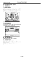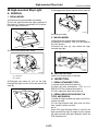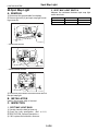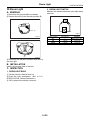
1
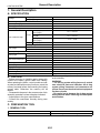
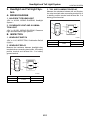
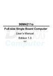
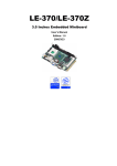
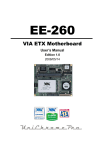
2004 LEGACY SERVICE MANUAL
QUICK REFERENCE INDEX
BODY SECTION
This service manual has been prepared
to provide SUBARU service personnel
with the necessary information and data
for the correct maintenance and repair
of SUBARU vehicles.
This manual includes the procedures
for maintenance, disassembling, reassembling, inspection and adjustment of
components and diagnostics for guidance of experienced mechanics.
Please peruse and utilize this manual
fully to ensure complete repair work for
satisfying our customers by keeping
their vehicle in optimum condition.
When replacement of parts during
repair work is needed, be sure to use
SUBARU genuine parts.
All information, illustration and specifications contained in this manual are
based on the latest product information
available at the time of publication
approval.
FUJI HEAVY INDUSTRIES LTD.
HVAC SYSTEM
(HEATER, VENTILATOR AND A/C)
AC
HVAC SYSTEM (AUTO A/C)
(DIAGNOSTICS)
AC(diag)
AIRBAG SYSTEM
AB
AIRBAG SYSTEM (DIAGNOSTICS)
AB(diag)
SEAT BELT SYSTEM
SB
LIGHTING SYSTEM
LI
WIPER AND WASHER SYSTEMS
WW
ENTERTAINMENT
ET
COMMUNICATION SYSTEM
COM
GLASS/WINDOWS/MIRRORS
GW
BODY STRUCTURE
BS
INSTRUMENTATION/DRIVER INFO
IDI
SEATS
SE
SECURITY AND LOCKS
SL
SUNROOF/T-TOP/CONVERTIBLE TOP
(SUNROOF)
SR
EXTERIOR/INTERIOR TRIM
EI
EXTERIOR BODY PANELS
EB
G2320GE7
2003 LEGACY SERVICE MANUAL
QUICK REFERENCE INDEX
BODY SECTION
CRUISE CONTROL SYSTEM
CC
CRUISE CONTROL SYSTEM
(DIAGNOSTICS)
CC(diag)
IMMOBILIZER (DIAGNOSTICS)
IM(diag)
LAN SYSTEM (DIAGNOSTICS)
LAN(diag)
G2320GE7
LIGHTING SYSTEM
LI
1.
2.
3.
4.
5.
6.
7.
8.
9.
10.
11.
12.
13.
14.
15.
16.
17.
18.
19.
20.
21.
22.
23.
24.
25.
26.
27.
28.
29.
30.
31.
32.
33.
34.
35.
Page
General Description ....................................................................................2
Headlight and Tail Light System .................................................................3
Front Fog Light System...............................................................................4
Rear Fog Light System ...............................................................................5
Turn Signal Light and Hazard Light System................................................6
Back-up Light System .................................................................................7
Stop Light System .......................................................................................8
Room Light System.....................................................................................9
Combination Switch (Light) .......................................................................10
Headlight Beam Leveler System...............................................................12
Combination Base Switch Assembly.........................................................13
Headlight Assembly ..................................................................................14
Headlight Bulb...........................................................................................18
Front Turn Signal Light Bulb .....................................................................19
Clearance/Parking Light Bulb....................................................................20
Front Fog Light Assembly .........................................................................21
Front Fog Light Bulb..................................................................................22
Rear Fog Light ..........................................................................................23
Side Turn Signal Light Assembly ..............................................................24
Rear Combination Light Assembly............................................................25
Tail/Stop Light Bulb ...................................................................................26
Rear Turn Signal Light Bulb ......................................................................27
Back-up Light Assembly............................................................................28
Back-up Light Bulb ....................................................................................29
Rear Fog Light Bulb ..................................................................................30
License Plate Light Assembly ...................................................................31
License Plate Light....................................................................................32
High-mounted Stop Light ..........................................................................33
Spot Map Light ..........................................................................................34
Room Light................................................................................................35
Luggage Room Light.................................................................................36
Trunk Room Light......................................................................................37
Glove Box Light.........................................................................................38
Door Step Light .........................................................................................39
Ignition Switch Illumination........................................................................40
General Description
LIGHTING SYSTEM
1. General Description
A: SPECIFICATION
Halogen type low beam
Halogen type high beam
Headlight
12 V — 55 W
12 V — 60 W
12 V — 21 W
12 V — 5 W
12 V — 55 W
12 V — 2.7 W (LED)
Front turn signal light
Clearance/parking light
Front fog light
Side turn signal light
Tail/stop light (Model with
rear fog light)
Tail light (Model without rear
Sedan
fog light)
Stop light (Model without
rear fog light)
Wagon Tail/stop light
Turn signal light
Sedan
Wagon
Rear combination light
Back-up light
License plate light
Sedan
Wagon
Sedan
Wagon
Rear fog light
High-mounted stop light
Interior light
Spot map light
Luggage room light
Trunk room light
Glove box light
Door step light
B: CAUTION
12 V — 5/21 W
12 V — 5/21 W
12 V — 21 W
12 V — 5/21 W
12 V — 21 W
12 V — 16 W
12 V — 21 W
12 V — 5 W
12 V — 21 W
12 V — 2 W (LED)
12 V — 21 W
12 V — 1.3 W (LED)
12 V — 8 W
12 V — 8 W
12 V — 13 W
12 V — 5 W
12 V — 1.4 W
12 V — 3.5 W
• After reassembly, make sure functional parts operate smoothly.
• Before removing or installing parts, always disconnect the battery ground cable from battery.
When replacing the audio, control module and other parts provided with memory functions, record the
memory contents before disconnecting the battery
ground cable. Otherwise, the memory will be
erased.
• Reassemble the parts in the reverse order of disassembly procedure unless otherwise indicated.
• Adjust parts to the given specifications.
• Connect the connectors securely during reassembly.
WARNING:
• The air bag system wiring harness is routed
near electrical parts and switches. All air bag
system wiring harnesses and connectors are
yellow. Do not use the electrical test equipment
on these circuits.
• Be careful not to damage the air bag system
wiring harness when servicing electrical parts
and switches.
C: PREPARATION TOOL
1. GENERAL TOOL
TOOL NAME
Circuit tester
REMARKS
Used for measuring resistance and voltage.
LI-2
Headlight and Tail Light System
LIGHTING SYSTEM
2. Headlight and Tail Light System
3. TAIL AND ILLUMINATION RELAY
Measure the resistance between tail and illumination relay terminals when connecting terminal No. 4
to battery positive terminal and terminal No. 3 to
battery ground terminal.
A: WIRING DIAGRAM
1. HALOGEN TYPE HEADLIGHT
<Ref. to WI-269, WIRING DIAGRAM, Headlight
System.>
(1)
2. CLEARANCE LIGHT AND ILLUMINATION LIGHT
(2)
<Ref. to WI-259, WIRING DIAGRAM, Clearance
Light and Illumination Light System.>
(3)
B: INSPECTION
(2)
(1)
(3)
(4)
(4)
LI-00001
1. HEADLIGHT SWITCH
<Ref. to LI-10, INSPECTION, Combination Switch
(Light).>
Current
Flow
No flow
2. HEADLIGHT RELAY
Measure the resistance between headlight relay
terminals when connecting terminal No. 4 to battery
positive terminal and terminal No. 3 to battery
ground terminal.
(1)
(2)
(1)
(3)
(4)
(2)
(3)
(4)
LI-00001
Current
Flow
No flow
Terminal No.
1 and 2
Standard
Less than 1 Ω
More than 1 MΩ
LI-3
Terminal No.
1 and 2
Standard
Less than 1 Ω
More than 1 MΩ
Front Fog Light System
LIGHTING SYSTEM
3. Front Fog Light System
A: WIRING DIAGRAM
1. FRONT FOG LIGHT
<Ref. to WI-267, WIRING DIAGRAM, Front Fog
Light System.>
B: INSPECTION
1. FRONT FOG LIGHT SWITCH
Measure the resistance between front fog light
switch terminals.
<Ref. to LI-10, INSPECTION, Combination Switch
(Light).>
2. FRONT FOG LIGHT RELAY
Measure the resistance between front fog light relay terminals when connecting terminal No. 4 to
battery positive terminal and terminal No. 3 to battery ground terminal.
(1)
(2)
(1)
(3)
(4)
(2)
(3)
(4)
LI-00001
Current
Flow
No flow
Terminal No.
1 and 2
Standard
Less than 1 Ω
More than 1 MΩ
LI-4
Rear Fog Light System
LIGHTING SYSTEM
4. Rear Fog Light System
A: WIRING DIAGRAM
1. REAR FOG LIGHT
<Ref. to WI-279, WIRING DIAGRAM, Rear Fog
Light System.>
B: INSPECTION
1. REAR FOG LIGHT SWITCH
Measure the rear fog light switch resistance between terminals. <Ref. to LI-10, INSPECTION,
Combination Switch (Light).>
2. REAR FOG LIGHT RELAY
Measure the resistance between rear fog light relay
terminals while connecting terminal No. 4 to battery
positive terminal and No. 3 to battery ground terminal.
(1)
(2)
(1)
(3)
(4)
(2)
(3)
(4)
LI-00001
Current
Flow
No flow
Terminal No.
1 and 2
Standard
Less than 1 Ω
More than 1 MΩ
LI-5
Turn Signal Light and Hazard Light System
LIGHTING SYSTEM
5. Turn Signal Light and Hazard
Light System
A: WIRING DIAGRAM
1. TURN SIGNAL LIGHT AND HAZARD
LIGHT SYSTEM
<Ref. to WI-282, WIRING DIAGRAM, Turn Signal
Light and Hazard Light System.>
B: INSPECTION
1. TURN SIGNAL SWITCH
<Ref. to LI-10, INSPECTION, Combination Switch
(Light).>
2. HAZARD SWITCH
Measure the resistance between hazard switch terminals.
4
3 2
1
LI-00261
Switch position
OFF
ON
Terminal No.
2 and 3
Standard
More than 1 MΩ
Less than 1 Ω
3. TURN SIGNAL LIGHT AND HAZARD
LIGHT MODULE
Connect the battery and turn signal light bulb to the
module. The module is properly functioning if it
blinks when power is supplied to the circuit.
3
2 1
8 7 6 5 4
LI-00262
LI-6
Back-up Light System
LIGHTING SYSTEM
6. Back-up Light System
battery positive terminal and terminal No. 3 to battery ground terminal.
A: WIRING DIAGRAM
1. BACK-UP LIGHT
(1)
<Ref. to WI-257, WIRING DIAGRAM, Back-up
Light System.>
(2)
(1)
(3)
(4)
(2)
B: INSPECTION
1. BACK-UP LIGHT SWITCH (MT MODEL)
(3)
(4)
Measure the resistance between back-up light
switch terminals.
LI-00001
Current
Flow
No flow
2 1
Terminal No.
1 and 2
Standard
Less than 1 Ω
More than 1 MΩ
NOTE:
Check other than back-up light relay. <Ref. to 4AT52, INSPECTION, Inhibitor Switch.>
LI-00263
Switch position
When shift lever is
set in reverse
position
Other positions
Terminal No.
1 and 2
Standard
Less than 1 Ω
More than 1 MΩ
2. INHIBITOR SWITCH (4AT MODEL)
Measure the resistance between inhibitor switch
terminals.
6 5 4 3 2 1
12 11 10 9 8 7
LI-00005
Switch position
When the selector lever is in “R”
range
Other positions
Terminal No.
1 and 2
Standard
Less than 1 Ω
More than 1 MΩ
3. BACK-UP LIGHT RELAY (5AT MODEL)
Measure the resistance between back-up light relay terminals when connecting terminal No. 4 to
LI-7
Stop Light System
LIGHTING SYSTEM
7. Stop Light System
A: WIRING DIAGRAM
1. STOP LIGHT
<Ref. to WI-281, WIRING DIAGRAM, Stop Light
System.>
B: INSPECTION
1. STOP LIGHT SWITCH
Measure the resistance between stop light switch
terminals.
(1)
2 1
(2)
2 1
4 3
LI-00265
(1) Model without cruise control
(2) Model with cruise control
Switch position
When brake pedal
is depressed
When brake pedal
is released
Terminal No.
Model without
cruise control: 1
and 2
Model with cruise
control: 2 and 3
Standard
Less than 1 Ω
More than 1 MΩ
LI-8
Room Light System
LIGHTING SYSTEM
8. Room Light System
3. TRUNK ROOM LIGHT SWITCH
A: WIRING DIAGRAM
Measure the resistance between trunk room light
switch terminals.
1. INTERIOR LIGHT
<Ref. to WI-271, WIRING DIAGRAM, Interior Light
System.>
3 2 1
B: INSPECTION
1. DOOR SWITCH
Measure the resistance between door switch terminals.
LI-00277
Switch position
When trunk lid is
opened
When trunk lid is
closed
1
2
3
LI-00007
Switch position
When door is
opened
When door is
closed
Terminal No.
Standard
Less than 1 Ω
1 and 3
More than 1 MΩ
2. REAR GATE LATCH SWITCH
Measure the resistance between rear gate latch
switch terminals.
1
2
LI-00276
Switch position
When rear gate is
opened
When rear gate is
closed
Terminal No.
Standard
Less than 1 Ω
1 and 2
More than 1 MΩ
LI-9
Terminal No.
Standard
Less than 1 Ω
1 and 3
More than 1 MΩ
Combination Switch (Light)
LIGHTING SYSTEM
9. Combination Switch (Light)
6) Remove the screws which secure switch, then
remove the combination switch.
A: REMOVAL
1) Disconnect the ground cable from battery.
2) Remove the instrument panel lower cover. <Ref.
to EI-56, REMOVAL, Instrument Panel Assembly.>
3) Remove the screws and remove the steering
column cover (upper and lower).
OFF
OFF
LI-00331
B: INSTALLATION
Install in the reverse order of removal.
C: INSPECTION
Measure the resistance between combination
switch terminals.
SL-00258
4) Disconnect the connector from combination
switch.
5) Remove three screws, and pull the combination
base switch assembly toward you. (Only for KA
model)
(A)
8
17
7 6 5 4 3
2
16 1514131211 10
1
9
8
17
7
6 5 4 3 2
16 1514131211 10
1
9
(B)
LI-00184
(A) LHD and EK model
(B) KA model
LI -00332
1. LIGHTING SWITCH
• LHD model
Switch position
OFF
Tail
Head
LI-10
Terminal No.
—
14 and 16
13, 14 and 16
Standard
More than 1 MΩ
Less than 1 Ω
Less than 1 Ω
Combination Switch (Light)
LIGHTING SYSTEM
4. FRONT FOG LIGHT
• EK model
Switch position
OFF
Tail
Head
Terminal No.
—
14 and 16
13, 14 and 10
Standard
More than 1 MΩ
Less than 1 Ω
Less than 1 Ω
• KA model
Switch position
OFF
Tail
Head
Switch position
OFF
ON
Terminal No.
—
15 and 9
14, 15 and 9
Standard
More than 1 MΩ
Less than 1 Ω
Less than 1 Ω
• LHD model
Terminal No.
7, 8 and 16
17 and 16
7 and 16
Standard
Less than 1 Ω
Less than 1 Ω
Less than 1 Ω
Switch position
OFF
ON
Switch position
OFF
ON
Switch position
OFF
ON
Terminal No.
8, 7 and 10
17 and 10
7 and 10
Standard
Less than 1 Ω
Less than 1 Ω
Less than 1 Ω
Terminal No.
1, 2 and 9
10 and 9
2 and 9
Standard
Less than 1 Ω
Less than 1 Ω
Less than 1 Ω
• LHD model/EK model
Terminal No.
1 and 2
—
2 and 3
Standard
Less than 1 Ω
More than 1 MΩ
Less than 1 Ω
Terminal No.
6 and 7
—
7 and 8
Standard
Less than 1 Ω
More than 1 MΩ
Less than 1 Ω
• KA model
Switch position
Left
Neutral
Right
Standard
More than 1 MΩ
Less than 1 Ω
12 and 16
Terminal No.
—
12 and 10
Standard
More than 1 MΩ
Less than 1 Ω
Terminal No.
Standard
More than 1 MΩ
Less than 1 Ω
• KA model
3. TURN SIGNAL SWITCH
Switch position
Left
Neutral
Right
Terminal No.
• LHD model/EK model
• KA model
Switch position
Passing
Low beam
High beam
Standard
More than 1 MΩ
Less than 1 Ω
5. REAR FOG LIGHT
• EK model
Switch position
Passing
Low beam
High beam
Terminal No.
—
10 and 11
• KA model
2. DIMMER & PASSING SWITCH
Switch position
Passing
Low beam
High beam
• LHD model/EK model
LI-11
16 and 13
Headlight Beam Leveler System
LIGHTING SYSTEM
10.Headlight Beam Leveler System
A: WIRING DIAGRAM
1. HEADLIGHT BEAM LEVELER SYSTEM
<Ref. to WI-243, WIRING DIAGRAM, Headlight
Beam Leveler System.>
B: INSPECTION
1. HEADLIGHT BEAM LEVELER ACTUATOR
1) Turn on the headlights.
2) Confirm the headlight beam level is lowered by
changing the switch position to 0 → 1 → 2 → 3 →
4 → 5.
2. HEADLIGHT BEAM LEVELER SWITCH
Connect the battery and headlight beam leveler
switch connector to the circuit tester. Measure the
voltage at each switch position.
3
2 1
8 7 6 5 4
v
LI-00270
Switch position
0
1
2
3
4
5
Terminal No.
Standard
6, 7 (+) and battery (−)
Battery voltage
Battery voltage
Battery voltage
Battery voltage
Battery voltage
Battery voltage
LI-12
Combination Base Switch Assembly
LIGHTING SYSTEM
11.Combination Base Switch
Assembly
2. PARKING SWITCH
Measure the resistance between parking switch
terminals.
A: REMOVAL
1) Remove the driver’s airbag module. <Ref. to AB14, REMOVAL, Driver’s Airbag Module.>
2) Remove the steering wheel. <Ref. to PS-20, REMOVAL, Steering Wheel.>
3) Remove the screws and remove the steering
column lower cover.
2 1
4 3
LI-00183
Switch position
OFF
ON
SL-00258
4) Remove the combination switch. <Ref. to LI-10,
REMOVAL, Combination Switch (Light).> <Ref. to
WW-8, REMOVAL, Combination Switch (Wiper).>
5) Remove the four screws and remove the roll
connector.
6) Remove the three screws.
LI-00271
7) Disconnect the connector and remove the combination base switch assembly.
B: INSTALLATION
1) Install in the reverse order of removal.
2) Before installing steering wheel, be sure the direction of roll connector is adjusted with steering.
<Ref. to AB-23, ADJUSTMENT, Roll Connector.>
C: INSPECTION
1. COMBINATION BASE SWITCH ASSEMBLY
Inspect the combination base switch assembly and
roll connector for crack or deformation. If any damage is found, replace with a new one.
LI-13
Terminal No.
2 and 4
1 and 4
Standard
Less than 1 Ω
Less than 1 Ω
Headlight Assembly
LIGHTING SYSTEM
12.Headlight Assembly
1) Remove the headlight assembly. <Ref. to LI-14,
REMOVAL, Headlight Assembly.>
2) Remove the eight screws.
A: REMOVAL
1) Disconnect the ground cable from battery.
2) Remove the air intake duct. (When removing the
headlight RH)
LI-00327
3) Remove headlight side bracket.
LI-00273
(A)
3) Remove the front grille. <Ref. to EI-24, REMOVAL, Front Grille.>
4) Remove the front bumper. <Ref. to EI-30, REMOVAL, Front Bumper.>
5) Disconnect each harness connector.
6) Remove the 4 bolts and disengage clips, and
then detach the headlight assembly.
LI-00328
(A) Headlight side bracket
4) Heat the sealing portion between headlight assembly and lens using heating gun.
LI-00274
B: INSTALLATION
Install in the reverse order of removal.
C: DISASSEMBLY
CAUTION:
• Do not touch the bulb glass portion.
• Do not touch inside the lens (extension portion) or reflector portion.
• Replace the packing with a new one.
LI-14
Headlight Assembly
LIGHTING SYSTEM
CAUTION:
Avoid heating one specific point of the seal portion and heating the headlight assembly to
100°C (212°F) or more.
CAUTION:
Completely remove the packing not to leave
any chips behind.
(A)
(A)
LI-00060
(C)
(A) Packing
(B)
D: ASSEMBLY
1) Cut the tip of packing (A) at an angle of 45°.
2) With the cut end facing upward, insert packing
(A) into the groove around the seal.
(C)
CAUTION:
• If the packing protrudes, slowly take it off the
groove.
• Do not stretch the packing. If the packing is
stretched, seal fails.
LI-00329
(A) Headlight ASSY upper
(B) Headlight ASSY lower
(C) Heated portion
(A)
5) Unhook the hook, and then take the lens off the
headlight assembly.
LI-00061
(A) Packing
LI-00330
6) Remove the packing (A) from seal groove.
3) After making a round of the seal, cut its tip at an
angle of 45°, with its length 10 mm (0.39 in) longer
than the circumference of seal so that the tip overlaps the other. Then, press it onto the seal, using a
screwdriver.
10mm
LI-00062
LI-15
Headlight Assembly
LIGHTING SYSTEM
4) Match the positions of the lens and headlight assembly, and then insert the lens into the headlight
assembly.
CAUTION:
Remove the turn signal light bulb and clearance/parking light bulb before removing the
lens.
5) Secure the hook, and then install the clip and
screw.
6) Put the seal portion of headlight assembly into
the water and check that water does not enter inside the headlight.
CAUTION:
Be sure that water does not enter inside the
headlight through the bulb socket and ventilation hole.
E: ADJUSTMENT
1. HEADLIGHT AIMING
CAUTION:
Turn off the light before adjusting headlight
beam level. If the light is necessary to check
aiming, do not turn on for more than two minutes.
NOTE:
Before checking the headlight beam level, be sure
of the following:
• The area around the headlight has not sustained
any accident, damage or other type of deformation.
• Vehicle is parked on a level surface.
• The inflation pressure of tires is correct.
• Vehicle’s fuel tank is fully filled.
1) Bounce the vehicle several times to normalize
the suspension.
2) Make certain that someone is seated in the driver’s seat.
3) Turn the headlights on and then adjust the low
beam pattern.
NOTE:
• Position the headlight beam leveler switch to “0”.
• Adjust the vertical aim (A) first, then horizontal
aim (B).
(B)
(A)
LI-00275
LI-16
Headlight Assembly
LIGHTING SYSTEM
(A)
W1
W2
W
H
h
W2
W
W1
(A)
(B)
h
H
(C)
LI-00324
(A)
Vehicle center
(B)
Bulb center marking
(C)
3 m (10 ft)
Illustration above shows the illumination pattern for LHD model. Illumination pattern for RHD model is symmetrically opposite.
H mm (in)
W mm (in)
1,180 (46.46)
Sedan
640 (25.20)
Wagon
Except for OUTBACK
635 (25.00)
LI-17
OUTBACK
705 (27.76)
h mm (in)
at 3 m (10 ft)
30 (1.18)
Headlight Bulb
LIGHTING SYSTEM
13.Headlight Bulb
7) Remove the light bulb retaining spring (A) to remove bulb.
A: REMOVAL
1. HIGH BEAM AND LOW BEAM
(A)
CAUTION:
• Because the halogen bulb operates at a high
temperature, dirt and oil on the bulb surface reduces the bulb’s service life. Hold the flange
portion when replacing the bulb. Never touch
the glass portion.
• Do not leave the headlight without a bulb for
a long time. Dust, moisture, etc. entering the
headlight may affect its performance.
1) Disconnect the ground cable from battery.
2) Remove the air intake duct. (When removing the
headlight bulb RH).
LI-00279
B: INSTALLATION
Install in the reverse order of removal.
C: INSPECTION
1. HALOGEN TYPE
1) Visually check the bulb for blow out.
2) Check the bulb specification.
<Ref. to LI-2, SPECIFICATION, General Description.>
3) If NG, replace the bulb with a new one.
LI-00273
3) Remove the battery cover. (When removing the
headlight bulb LH).
4) Tilt the washer tank filler neck. (When removing
the headlight bulb LH).
5) Disconnect the harness connector.
6) Remove the bulb assembly (A) to remove high
beam. To remove the low beam, remove the back
cover (B), and then go to Step 7.
(B)
(A)
LI-00278
LI-18
Front Turn Signal Light Bulb
LIGHTING SYSTEM
14.Front Turn Signal Light Bulb
A: REMOVAL
1) When removing the turn signal light bulb, fully
turn the steering wheels to opposite direction from
desired turn signal light bulb.
(3)
(2)
(1)
LI-00311
(1) Turn the steering wheel fully.
(2) Mud guard
(3) Front turn signal light
2) Turn the mud guard inward.
3) Turn the socket (A) from wheel arch part, and
then remove the front turn signal light bulb.
(A)
LI-00283
CAUTION:
For 5AT model, remove the turn signal light
bulb LH from engine compartment with removing battery, because it can not be removed from
wheel arch part.
B: INSTALLATION
Install in the reverse order of removal.
C: INSPECTION
1) Visually check the bulb for blow out.
2) Check the bulb specification.
<Ref. to LI-2, SPECIFICATION, General Description.>
3) If NG, replace the bulb with a new one.
LI-19
Clearance/Parking Light Bulb
LIGHTING SYSTEM
15.Clearance/Parking Light Bulb
A: REMOVAL
1) Remove the air intake duct. (When removing the
clearance light/parking light bulb RH).
LI-00273
2) Remove the battery cover. (When removing the
clearance light/parking light bulb LH)
3) Tilt the washer tank filler neck. (When removing
the clearance/parking light bulb)
4) Remove the headlight low beam back cover (B).
5) Turn the socket (A) and remove the bulb.
(B)
(A)
LI-00285
B: INSTALLATION
Install in the reverse order of removal.
C: INSPECTION
1) Visually check the bulb for blow out.
2) Check the bulb specification. <Ref. to LI-2,
SPECIFICATION, General Description.>
3) If NG, replace the bulb with a new one.
LI-20
Front Fog Light Assembly
LIGHTING SYSTEM
16.Front Fog Light Assembly
2. OUTBACK MODEL
A: REMOVAL
1) Disconnect the ground cable from battery.
2) Remove the two clips, and then turn over the
lower mud guard.
1. EXCEPT FOR OUTBACK MODEL
1) Disconnect the ground cable from battery.
2) Remove the front fog light cover (A).
(A)
LI-00288
LI-00287
3) Disengage the two clips, and then turn over the
lower mud guard.
3) Disconnect the harness connector.
4) Remove the mounting bolts, and then detach the
fog light assembly by pulling it.
LI-00325
B: INSTALLATION
LI-00288
4) Disconnect the harness connector.
5) Remove the mounting bolts, and then detach the
fog light assembly by pulling it.
Install in the reverse order of removal.
CAUTION:
When installing the fog light assembly, be sure
to secure the upper hock.
LI-00289
LI-00326
LI-21
Front Fog Light Bulb
LIGHTING SYSTEM
17.Front Fog Light Bulb
A: REMOVAL
1) Disconnect the ground cable from battery.
2) Disengage the two clips, and then turn over the
lower mud guard.
LI-00288
3) Disconnect the harness connector.
4) Remove the back cover.
LI-00291
5) Remove the spring retainer then detach the fog
light bulb.
B: INSTALLATION
Install in the reverse order of removal.
C: INSPECTION
1) Visually check the bulb for blow out.
2) Check the bulb specification. <Ref. to LI-2,
SPECIFICATION, General Description.>
3) If NG, replace the bulb with a new one.
LI-22
Rear Fog Light
LIGHTING SYSTEM
18.Rear Fog Light
A: REMOVAL
NOTE:
Rear fog light is installed to rear combination light
of driver’s side for sedan and rear gate garnish of
driver’s side for wagon.
1. SEDAN MODEL
Remove the rear combination light. <Ref. to LI-25,
REMOVAL, Rear Combination Light Assembly.>
2. WAGON MODEL
1) Remove the rear gate trim. <Ref. to EI-69, REMOVAL, Rear Gate Trim.>
2) Disconnect the harness connectors and remove
the rear gate garnish. <Ref. to EI-76, REMOVAL,
Rear Gate Garnish.>
3) Remove the mounting nuts and detach the rear
fog light assembly.
LI-00292
B: INSTALLATION
Install in the reverse order of removal.
LI-23
Side Turn Signal Light Assembly
LIGHTING SYSTEM
19.Side Turn Signal Light Assembly
A: REMOVAL
1) Disconnect the ground cable from battery.
2) Remove the scalp caps. <Ref. to GW-17, REPLACEMENT, Scalp Cap.>
3) Remove the mirror. <Ref. to GW-19, REPLACEMENT, Outer Mirror.>
4) Disconnect the harness connector, remove the 3
mounting screws and then remove the side turn
signal light assembly.
LI-00293
B: INSTALLATION
Install in the reverse order of removal.
C: INSPECTION
1) Install the side turn signal light assembly and
check that it blinks normally.
2) If it does not blink normally, replace the side turn
signal light assembly with a new one.
NOTE:
Since LED (Light Emitting Diode) is used for side
turn signal light, replace the side turn signal light
assembly when the LED is powered off.
LI-24
Rear Combination Light Assembly
LIGHTING SYSTEM
20.Rear Combination Light Assembly
4) Remove the two bolts, and then detach the rear
combination light by pulling it to the rear side of vehicle.
A: REMOVAL
1. SEDAN MODEL
1) Disconnect the ground cable from battery.
2) Remove the trunk room side trim. <Ref. to EI-71,
REMOVAL, Trunk Room Trim.>
3) Remove the four nuts, and then detach the rear
combination light after disconnecting the connector.
LI-00296
5) Remove the rear combination light after turning
the socket of tail/stop light bulb and rear turn signal
light bulb to remove the bulbs.
B: INSTALLATION
Install in the reverse order of removal.
LI-00294
2. WAGON MODEL
1) Disconnect the ground cable from battery.
2) Remove the clips.
LI-00295
3) While pressing the portion (A), insert your finger
or flat-tip screwdriver wrapped with tape into the
clearance (B) to remove pawls in the order of (C),
(D), (E), and remove the rear combination cover.
(E)
(C)
(A)
(D)
(B)
LI-00284
LI-25
Tail/Stop Light Bulb
LIGHTING SYSTEM
21.Tail/Stop Light Bulb
A: REMOVAL
1. SEDAN MODEL
1) Remove the trunk side trim cover.
2) Turn the socket and remove the bulb.
(A)
(B)
LI-00297
Model without rear fog light
(A) Tail light
(B) Stop light
Model with rear fog light
(A) Tail/stop light
(B) Rear fog light (Driver’s side only)
2. WAGON MODEL
1) Remove the rear combination light assembly.
<Ref. to LI-25, WAGON MODEL, REMOVAL, Rear
Combination Light Assembly.>
2) Turn the socket and remove the bulb.
LI-00298
B: INSTALLATION
Install in the reverse order of removal.
C: INSPECTION
1) Visually check the bulb for blow out.
2) Check the bulb specification. <Ref. to LI-2,
SPECIFICATION, General Description.>
3) If NG, replace the bulb with a new one.
LI-26
Rear Turn Signal Light Bulb
LIGHTING SYSTEM
22.Rear Turn Signal Light Bulb
A: REMOVAL
1. SEDAN MODEL
1) Remove the trunk side trim cover.
2) Turn the socket and remove the bulb.
LI-00299
2. WAGON MODEL
1) Remove the rear combination light assembly.
<Ref. to LI-25, WAGON MODEL, REMOVAL, Rear
Combination Light Assembly.>
2) Turn the socket and remove the bulb.
LI-00300
B: INSTALLATION
Install in the reverse order of removal.
C: INSPECTION
1) Visually check the bulb for blow out.
2) Check the bulb specification. <Ref. to LI-2,
SPECIFICATION, General Description.>
3) If NG, replace the bulb with a new one.
LI-27
Back-up Light Assembly
LIGHTING SYSTEM
23.Back-up Light Assembly
A: REMOVAL
NOTE:
In case of model with rear fog light, back-up light is
installed to only passenger’s side.
1. SEDAN MODEL
Remove the rear combination light. <Ref. to LI-25,
REMOVAL, Rear Combination Light Assembly.>
2. WAGON MODEL
1) Remove the rear gate trim. <Ref. to EI-69, REMOVAL, Rear Gate Trim.>
2) Disconnect the harness connectors and remove
the rear gate garnish. <Ref. to EI-76, REMOVAL,
Rear Gate Garnish.>
3) Remove the mounting nuts and detach the backup light assembly.
LI-00301
B: INSTALLATION
Install in the reverse order of removal.
LI-28
Back-up Light Bulb
LIGHTING SYSTEM
24.Back-up Light Bulb
A: REMOVAL
1. SEDAN MODEL
1) Remove the bulb inspection cover of trunk side
trim.
2) Turn the socket and remove the bulb.
LI-00304
2. WAGON MODEL
1) Remove the bulb inspection cover of rear gate
trim.
2) Turn the socket and remove the bulb.
LI-00305
B: INSTALLATION
Install in the reverse order of removal.
C: INSPECTION
1) Visually check the bulb for blow out.
2) Check the bulb specification. <Ref. to LI-2,
SPECIFICATION, General Description.>
3) If NG, replace the bulb with a new one.
LI-29
Rear Fog Light Bulb
LIGHTING SYSTEM
25.Rear Fog Light Bulb
A: REMOVAL
1. SEDAN MODEL
1) Remove the bulb inspection cover of trunk side
trim.
2) Turn the socket and remove the bulb.
LI-00302
2. WAGON MODEL
1) Remove the rear fog light assembly. <Ref. to LI23, REMOVAL, Rear Fog Light.>
2) Remove the mounting screws, and then remove
the rear fog light assembly.
LI-00292
B: INSTALLATION
Install in the reverse order of removal.
C: INSPECTION
1. SEDAN MODEL
1) Visually check the bulb for blow out.
2) Check the bulb specification. <Ref. to LI-2,
SPECIFICATION, General Description.>
3) If NG, replace the bulb with a new one.
2. WAGON MODEL
1) Install the rear fog light assembly to check that it
illuminate normally.
2) If it does not illuminate, replace the rear fog light
assembly with a new one.
NOTE:
Since LED (Light Emitting Diode) is used for the
rear fog light, replace the rear fog light assembly
when the LED is powered off.
LI-30
License Plate Light Assembly
LIGHTING SYSTEM
26.License Plate Light Assembly
A: REMOVAL
1. SEDAN MODEL
1) Remove the trunk lid garnish. <Ref. to EI-75,
REMOVAL, Trunk Lid Garnish.>
2) Remove the trunk lid trim. <Ref. to EI-71,
TRUNK LID TRIM, REMOVAL, Trunk Room Trim.>
3) Turn and remove the bulb socket (A). Disengage
the clip (B) and remove the license plate light assembly.
(B)
(B)
(A)
LI-00306
B: INSTALLATION
Install in the reverse order of removal.
LI-31
License Plate Light
LIGHTING SYSTEM
27.License Plate Light
A: REMOVAL
1. SEDAN MODEL
1) Remove the trunk lid trim. <Ref. to EI-71,
TRUNK LID TRIM, REMOVAL, Trunk Room Trim.>
2) Turn and remove the bulb socket (A).
(A)
LI-00307
3) Remove the bulb.
2. WAGON MODEL
1) Remove the license plate light mounting screw
(A) and then remove the lens (B).
(B)
(A)
(B)
(A)
LI-00308
2) Remove the bulb.
B: INSTALLATION
Install in the reverse order of removal.
C: INSPECTION
1) Visually check the bulb for blow out.
2) Check the bulb specification. <Ref. to LI-2,
SPECIFICATION, General Description.>
3) If NG, replace the bulb with a new one.
LI-32
High-mounted Stop Light
LIGHTING SYSTEM
28.High-mounted Stop Light
5) Disengage three claws and remove the lens (A).
A: REMOVAL
1. SEDAN MODEL
1) Disconnect the ground cable from battery.
2) Push the high-mounted stop light backward of
the vehicle (1), raise the rear portion of it (2) and remove the clips to remove it.
(2)
(A)
LI-00310
6) Remove the bulb.
2. WAGON MODEL
(1)
1) Disconnect the ground cable from battery.
2) Detach the roof spoiler. <Ref. to EI-40, REMOVAL, Roof Spoiler.>
3) Remove the nuts (A), then detach the highmounted stop light.
LI-00333
3) Remove the harness from clamp.
(A)
(A)
(2)
LI-00312
(1)
LI-00334
B: INSTALLATION
Install in the reverse order of removal.
(1) Harness
(2) Clamp
C: INSPECTION
4) Disengage two claws (A), pull out the highmounted stop light from the cover and remove the
claw (B).
(A)
1. SEDAN (STANDARD TYPE)
1) Visually check the bulb for blow out.
2) Check the bulb specification. <Ref. to LI-2,
SPECIFICATION, General Description.>
3) If NG, replace the bulb with a new one.
2. SEDAN (REAR SPOILER BUILT-IN
TYPE) AND WAGON
(B)
1) Install the high-mounted stop light to test if it illuminates normally.
2) If the high-mounted stop light does not illuminate, replace it with a new one.
LI-00309
NOTE:
Since LED (Light Emitting Diode) is used for the
high-mounted stop light of wagon model, replace
the high-mounted stop light assembly when the
LED is powered off.
LI-33
Spot Map Light
LIGHTING SYSTEM
29.Spot Map Light
2. SPOT MAP LIGHT SWITCH
A: REMOVAL
Measure the resistance between spot map light
switch terminals.
1) Disconnect the ground cable from battery.
2) Remove the lens (A) and spot map light mounting screws (B).
(A)
LI-00313
• Model with sunroof
(B)
LI-00314
• Model without sunroof
(B)
(B)
LI-00320
3) Disconnect the harness connectors and remove
the spot map light.
B: INSTALLATION
Install in the reverse order of removal.
C: INSPECTION
1. SPOT MAP LIGHT BULB
1) Visually check the bulb for blow out.
2) Check the bulb specification. <Ref. to LI-2,
SPECIFICATION, General Description.>
3) If NG, replace the bulb with a new one.
LI-34
Switch position
OFF
ON
Terminal No.
—
1 and 2
Standard
More than 1 MΩ
18±5.4 Ω
Room Light
LIGHTING SYSTEM
30.Room Light
2. ROOM LIGHT SWITCH
A: REMOVAL
Measure the resistance between room light switch
terminals.
1) Disconnect the ground cable from battery.
2) Remove the lens (A) and mounting screws (B).
3 2 1
(A)
LI-00257
LI-00315
(B)
Switch position
OFF
ON
DOOR
LI-00316
3) Disconnect the harness connector and remove
the room light.
B: INSTALLATION
Install in the reverse order of removal.
C: INSPECTION
1. ROOM LIGHT BULB
1) Visually check the bulb for blow out.
2) Check the bulb specification. <Ref. to LI-2,
SPECIFICATION, General Description.>
3) If NG, replace the bulb with a new one.
LI-35
Terminal No.
—
1 and 3
2 and 3
Standard
More than 1 MΩ
1.5±0.5 Ω
1.5±0.5 Ω
Luggage Room Light
LIGHTING SYSTEM
31.Luggage Room Light
A: REMOVAL
1) Disconnect the ground cable from battery.
2) Remove luggage room light body (A).
(A)
LI-00258
3) Disconnect the harness connector and remove
the lens.
B: INSTALLATION
Install in the reverse order of removal.
C: INSPECTION
1. LUGGAGE ROOM LIGHT BULB
1) Visually check the bulb for blow out.
2) Check the bulb specification. <Ref. to LI-2,
SPECIFICATION, General Description.>
3) If NG, replace the bulb with a new one.
2. LUGGAGE ROOM LIGHT SWITCH
Measure the resistance between luggage room
light switch terminals.
3
2
1
LI-00259
Switch position
OFF
ON
DOOR
Terminal No.
—
1 and 2
2 and 3
Standard
More than 1 MΩ
1.5±0.5 Ω
1.5±0.5 Ω
LI-36
Trunk Room Light
LIGHTING SYSTEM
32.Trunk Room Light
A: REMOVAL
1) Disconnect the ground cable from battery.
2) Turn the trunk room light counterclockwise to
60° to remove it and disconnect the harness connector.
LI-00321
3) Remove the bulb (A).
(A)
LI-00286
B: INSTALLATION
Install in the reverse order of removal.
C: INSPECTION
1. TRUNK ROOM LIGHT BULB
1) Visually check the bulb for blow out.
2) Check the bulb specification. <Ref. to LI-2,
SPECIFICATION, General Description.>
3) If NG, replace the bulb with a new one.
2. TRUNK LID SWITCH (TRUNK ROOM
LIGHT SWITCH)
Measure the resistance between trunk lid switch
terminals.
3
2
1
LI-00290
LI-37
Trunk lid position
Close
Open
Terminal No.
1 and 3
Standard
More than 1 MΩ
1.5±0.5 Ω
Glove Box Light
LIGHTING SYSTEM
33.Glove Box Light
A: REMOVAL
1) Disconnect the ground cable from battery.
2) Remove the glove box. <Ref. to EI-51, REMOVAL, Glove Box.>
3) Disconnect the harness connector.
4) Remove the glove box light.
LI-00323
B: INSTALLATION
Install in the reverse order of removal.
C: INSPECTION
1) Visually check the bulb for blow out.
2) Check the bulb specification.
<Ref. to LI-2, SPECIFICATION, General Description.>
3) If NG, replace the bulb with a new one.
LI-38
Door Step Light
LIGHTING SYSTEM
34.Door Step Light
A: REMOVAL
1) Disconnect the ground cable from battery.
2) Remove the lens (A), and then remove the door
step light bulb.
(A)
LI-00266
3) Remove the front door trim. <Ref. to EI-48, REMOVAL, Door Trim.>
4) Disconnect the harness connector.
5) Remove the mounting screw from rear side of
trim and remove the door step light.
LI-00267
B: INSTALLATION
Install in the reverse order of removal.
C: INSPECTION
1) Visually check the bulb for blow out.
2) Check the bulb specification.
<Ref. to LI-2, SPECIFICATION, General Description.>
3) If NG, replace the bulb with a new one.
LI-39
Ignition Switch Illumination
LIGHTING SYSTEM
35.Ignition Switch Illumination
5) Turn the ignition switch illumination connector to
left and remove it.
A: REMOVAL
1) Disconnect the ground cable from battery.
2) Remove the screws and detach the upper column cover and lower column cover.
(B)
(A)
(C)
LI-00343
(A) Ignition switch illumination connector
(B) Ignition switch illumination
(C) Immobilizer antenna connector
SL-00258
3) Remove the instrument panel lower cover. <Ref.
to EI-56, REMOVAL, Instrument Panel Assembly.>
4) Disconnect the ignition switch illumination connector (A).
B: INSTALLATION
Install in the reverse order of removal.
C: INSPECTION
1
2
Step
CHECK IGNITION SWITCH ILLUMINATION.
Make sure the ignition switch illumination illuminates when driver’s side door is open.
CHECK IGNITION SWITCH ILLUMINATION.
Make sure the ignition switch illumination
blinks when ignition switch is turned to ON.
Check
Yes
No
Does the ignition switch illumi- Ignition switch illu- Go to step 2.
nation illuminate?
mination is normal.
Does the ignition switch illumi- Check the funcnation blink?
tion setting of body
integrated unit.
<Ref. to
LAN(diag)-2, Basic
Diagnostic Procedure.>
LI-40
Check the ignition
switch illumination
circuit. <Ref. to
SL-27, CHECK
IGNITION
SWITCH ILLUMINATION, INSPECTION, Keyless
Entry System.>