1
C)rqoNEEFr
RECEIVEDMAY
,,
88I
a This seruice manual describes the mechanical operations
and adjustments, and the D.D. motor employed in the
following models.
STEREO TURNTABLE
PLI
elclcl
FL-ElcIcIX
PLI?55
PLISOO
PL-3clcIX
PLI
4ocl
FrL-4.clclx
4-1. Mesu.o 1-chome. rvesuno-ku, Tokyo 153. Jap6n
CCIFIFEIF|ATICIN
PICINEEFI
E-ECTFIONIC
lr.g. P|q\IEEF ELEST':EINICB OGIPCFIATION 85 Oxfotu O.,ve, Moonach,e, New Jereey O7O7A, U.S A:
PIChIEEFI ELECTFIO TIC (Et-FleEl N,V. Lurthagen-Haven g, 2OS AnEwerp, Elelgrum
PIO\|EEF| ELECTFIONICB AIJATFaALIA FYY. LTO. 178-184 E]ounda.y Road, Elnaesde, VcEonra 3195, AusE.6l6
<ART-467-0>
r'@ocr.
i979 Printed in
Japan
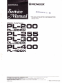
CONTENTS
1. PL-200PANELFAClLlTlES...
2. PL-255PANEL FAClLlTlES . ..
3. PL-400 PANEL FACILITIES . . .
4. PL-300 PANEL FACILITIES . . .
5. DISASSEMBLY
5.1 Paneland base plate
5.2 D.D.motorandtonearm .......10
6. PANEL AND BASE PLATE ASSEMBLY
6.1 PL-200,PL-300
.......11
6.2 PL-255,PL-400
.......12
7. CIRCUIT DESCRIPTIONS
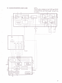
7 .1 Block diagram (PL-300, PL-400)
7.2 Motoroperation...
7.3 Operation of the PD1003 lC (oscillator
stase).
.......16
3
4
6
8
9
7.4
7.S
g.
9.
13
14
OperationofthepA2004 lC(comparator
sontrol)
. . .. ..
Operation of the pA200b lC (drive
.
sontrot)
Btock diasram (pL-200, pL-25b)
MECHANTSM DESCR;pTIONS
7.6
9.1 pL2ggmechanismoperating
8.2 pL-400 mechanicatoperation
16
1t
21
22
24
ADJUSTMENT
9.1 Stylusdescentposition
9.2 Auto return adjustment
9.3 D.D. motor adjustment (PL-300 and
PL-400)
.......29
9.4 D.D. motor adjustment (PL-200 and
PL-255)
28
28
29
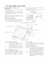
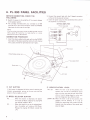
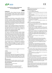
1. PL-2OO PANEL FACILITIES
BEFORE CONNECTING, CHECK THE
FOLLOWING:
o Switch the power to the amplif ier off to prevent
damage
to the speaker system.
The cartridge furnished with your turntable is an MM
type. Be sure to use a stereo amplifier which has PHONO
input.jacks for this type of cartridge.
.
Connect the ground lead with the Y-shaped connector
at the end to the ground terminal.
J. lnsert the power plug into the convehience AC outlet of
the amplifier or a wall outlet.
2.
STEREO AMPLIFIER
Phono input jacks
AC outlet
Power cord
NOTE:
lf you are using a low-output moving coil (MC) cartridge, you wilt
need a special MC transformer or a head amplifier, or a stereo
amplifier with a built-in MC amplif ier.
CONNECTION PROCEDURE
1. lnsert the phono cables (white and red) into the PHONO
input jacks of the stereo amplifier {white for left channel
into L jack, and red for right channel into R jack).
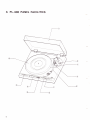
Ground lead
Dust cover
I
I
Platter/Rubber platter mat
-l-.-.-I
I
Anti-skate knob
Speed checking window
Arm rest
O speeo sELEcroR
BUTToN
45 . . .. . . When this button is depressed, the platter
will rotate at 45rpm. Depress for playing 45
33 . . . . . .
rpm records, singles or EP's.
When this button is set to the released posi-
tion, the platter will rotate at 33-1/3rpm.
Release for playing 33-1/3rpm records like
€) cuT
@ ARM-ELEVATTON LEVER
UP
( ! ):
o
crease when turned counterclockwise in the direction of
while the record is playing, the
tonearm automatically returns to the arm rest, and the
power to the turntable is cut off.
LP's.
spreo ADJUSTMENT KNOB
Turn this knob when finely adjusting the speed of the
platter. The speed of platter will increase when the knob
is turned clockwise in the direction of "+"; it will de-
BUTTON
lf this button is depressed
DOWN
(I
When this lever is set to this position, the
tonearm will rise, Set it to UP before record
play and when you want to stop record play
while a track is being played or when you
want to change over to a dif{erent track.
):When the lever is set to this position, the
tonearm
will be lowered. lf it is set to
DOWN for record ptay, the tonearm will be
lowered onto the surface of the record, and
play will begin.
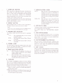
2. P1.255 PANEL FACILITIES
O srnnr/cur BUTToN
When this button is depressed, the power is turned on to
the turntable, the strobe light comes on and the platter
starts to rotate. With the RECORD SIZE SELECTOR
set at one
of the positions - 30, 25,or 17 - the tonearm
moves automatically to the record disc as the platter starts
rotating, thus starting record play.
lf this button is depressed while the record is playing, the
tonearm automatically returns to the arm rest, and the
power to the turntable is cut of f .
@
REPEAT BUTToN
Push this button when you want to listen to the same re.
cord again. Press the button once more to release.
€)
TOruEARM
This tonearm is designed to apply the correct tracking
force to the cartridge and to keep this force at the precise
level for faithful tracking of the record grooves. lt also has
the job of switching the power on to the turntable.
a When the tonearm is moved from the arm rest to the
platter, the power comes on, the strobe lamp lights up,
and the platter rotates.
a When the tonearm is returned to the arm rest, the
power to the turntable is cut off, the strobe lightgoes
off, and the platter stops rotating.
@ anu-eLEVATtoN
UP(!):
NOTE:
you have to do for repeat play is to press the BE?EAT
button. There is no need to push the START/CUT button again.
cord play and when you want to stop record play while a track is being played or
when you want to change over to a differ-
All
@ REcoRD SIzE
SELEcToR
This selector selects the size of the record for automatic
ent track.
DOWN (
play.
t ):
.
will be lowered. lf it is set to
DOWN for record play, the tonearm will
be lowered onto the surface of the record,
LP and EP records.
For the automatic play of 25cm (10-inch)
LP records.
12"30. . .
.
For the automatic play of 30cm (12-inch)
LP records.
@ SrnoeE LIGHT/SPEED cHEcKING WINDoW
This light comes on when the tonearm moves away from
the arm rest toward the platter. lt irradiates the stroboscope around the outside of the platter.
@ speeo
ADJUSTMENT KNoB
Turn this knob when delicately adjusting the speed of the
platter. The speed of platter will increase when the knob
is turned clockwise, in the direction of "+"; it will decrease when turned counterclockwise, in the direction of
@ speeo SELECTOR BUTTON
45.....
33
When this button is depressed, the platter will
rotate at 45rpm. Depress for playing 45rpm
records, singles or EP's.
When this button is set to the release position,
the platter will rotate at 33-1/3rpm. Release
for playing 33-1/3rpm records like LP's.
When the lever is set to this position, the
tonearm
7"17. .. . For the automatic play of 17cm (7-inch)
10"25. . .
LEVER
When this lever is set to this position, the
tonearm will rise. Set it to UP before re-
and play
E
will
begin.
ANTI.SKATE KNoB
This knob is used to cancel out the harmful skating force
which is generated during record play.
@ NNU
REST/cLAMPER
The arm rest supports the tonearm when it is not being
used. Set the tonearm on its rest when it is not playing records. Clamp it into position if you don't have any immediate plans to play records.
O
plnrrER/RUBBER pLATTER MAT
When the tonearm is moved and power is supplied to the
turntable, the platter will start rotating at the set rotation
speed. The rubber platter mat stabilizes the records and
also absorbs external vibration.
@ ousr covER
Keep this closed unless operating the controls or tonearm,
or changing over records. This serves to keep dust from
adhering to the records during record play. When fully
opened and pulled straight up, this dust cover can be re,
moved from the cabinet.
3.
PL-4OO PANEL FACILITIES
O Srnnr/cuT BUTToN
When this.button is depressed, the power is turned on to
e
nnu-eLEVATIoN LEVER
UP
the turntable, the strobe light comes on and the platter
starts to rotate. With the RECORD SIZE SELECTOR
set at one of the positions - 30, 25, or 1 7 - the tonearm
(!
When this lever is set to this position, the
tonearm will rise. Set it to UP before re-
):
cord play and when you want to stop record play while a track is being played or
when you want to change over to a diff er-
moves automatically to the record disc as the platter starts
rotating, thus starting record play.
ent track.
lf this button
is depressed while the record is playing, the
tonearm automatically returns to the arm rest, and the
power to the turntable is cut off .
@
DOWN ( Y
):
will be lowered. lf it is set to
DOWN for record play, the tonearm will
be lowered onto the surface of the record,
tonearm
REPEAT BUTToN
Push this button when you want to listen to the same record again. Press the button once more to release.
When the lever is set to this position, the
and play
@ ANTI-SKATE
will
begin.
KNoB
NOTE:
This knob is used to cancel out the harmful skating force
All you have to doforrepeatplayisto presstheREPEAT button.
which is generated during record play.
There is no need to push the START/CUT button again.
@ REcoRD srzE sELEcroR
This selector selects the size of the record for automatic
play.
7"11 .
10"25
.
.. .
For the automatic play of 17cm (7-inch)
.
LP and EP records.
For the automatic play of 25cm (10-inch)
.
For the automatic play of 30cm (12-inch)
LP records.
12"30.
LP records.
@ STROBE LIGHT
This light comes on when the tonearm moves away from
the arm rest toward the platter. lt irradiates the stroboscope around the outside of the platter.
@
SPTCO SELECTOR BUTTON
45 . . .. . When this button is depressed, the platter will
rotate at 4Srpm. Depress for playing 45rpm
33 . . . . .
For further
details, see "ANTI SKATING ADJUST-
MENT".
records, singles or EP's.
When this button is set to the release position,
O
ARM REST/cLAMPER
The arm rest supports the tonearm when it is not being
used. Set the tonearm on its rest when it is not playing records. Clamp it into position if you don't have any immediate plans to play records.
OO PLATTER/RUBBER PLATTER MAT
When the tonearm is moved and power is supplied to the
turntable, the platter will start rotating at the set rotation
speed. The rubber platter mat stabilizes the records and
also absorbs external vibration.
O DUST coVER
Keep this closed unless operating the controls or tonearm,
or changing over records. This serves to keep dust from
adhering to the records during record play. When fully
opened and pulled straight up, this dust cover can be removed f rom the cabinet.
the platter will rotate at 33-1/3rpm. Release
for playing 33-1/3rpm records like Lp's.
@ roruEARM
This tonearm is designed to apply the correct tracking
force to the cartridge and to keep this force at the precise
level for faithful tracking of the record qrooves. lt also has
the job of switching the power on to the turntable.
a When the tonearm is moved from the arm rest
to the
platter, the power comes on, the strobe lamp lights up,
a
and the platter rotates.
When the tonearm is returned to the arm rest, the
power to the turntable is cut off, the strobe light goes
off, and the platter stops rotating.
7
4. PL-3OO PANEL FACILITIES
BEFORE CONNECTING, CHECK THE
FOLLOWING:
a Switch the power to the amplif ier off to prevent
o
the ground lead with the Y-shaped connector
at the end to the ground terminal.
3. lnsert the power plug into the convenience AC outlet of
2. Connect
damage
to the speaker system.
The cartridge furnished with your turntable is an MM
type. Be sure to use a stereo amplifier which has PHONO
input jacks for this type of cartridge.
the amplifier or
a
wall outlet.
STEREO AMPLIFIER
Phono input jacks
AC outlet
Power cord
NOTE:
lf you are using a low-output moving coit (MC) carttidge, you will
need a special MC transformer or a head amptifier, or a stereo
amplifier with a built-in MC amplifier.
CONNECTION PROCEDURE
1. lnsert the phono cables (white and red) into the PHONO
input jacks of the stereo amplifier (white for left channel
into L jack, and red for right channel into R jack).
Dust cover
Platter/Rubber platter mat
Anti-skate knob
Strobe lighr
Arm rest
O cur
BUTToN
lf this button is depressed
while the record is playing, the
tonearm automatically returns to the arm rest, and the
power to the turntable is cut off .
@ nnu-elEVATtoN LEVER
UP ( ! ):
When this lever is set to this position, the
@
SPCCO SELECTOR BUTTON
45 . . . . . . When this button is depressed, the platter
will rotate at 45rpm. Depress for playing 45
33 . . . . . .
rpm records, singles or EP's.
When this button is set to the released posi-
tion, the platter will rotate at 33-1/3rpm.
Release for playing 33-1/3rpm records like
LP's.
DOWN (
I
tonearm will rise. Set it to UP before record
play and when you want to stop record play
while a track is being played or when you
want to change over to a different track.
): When the lever is set to this position, the
tonearm will be lowered. lf it is set to
DOWN for record play. the tonearm will be
lowered onto the surface of the record, and
play will begin.
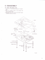
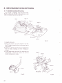
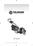
5. DISASSEMBLY
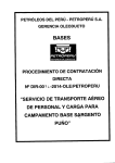
5.1
PANEL AND BASE PLATE
1. Undo tlne 4 screws O securing the insulator
legs.
2. Move
the tonearm across to the center,
and
little.
3. Disconnect the D.D. motor and circuit board
raise the panel a
connectors (2-pin and 5-pin).
}'.
Size
se
lector
G,-.\
,) P
t'1
Power
ass'v
./l
Motor Ass'y
rupply
s-pin colnnecto,.
a/
]
2-pin
connector
\
g
F
loat spring
(red)
U
-p
6
JK
\7
q
o
Float spring
(red)-@
g
@-
&
@
,JK
t--,
Float spring
(red)
CI
o
{
o
Fiq.5-1
I
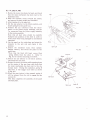
5.2
1.
D.D. MoroR AND ToNEARM
After removing the panel, undo the 3
screws
securing the motor.
2. Undo the 4 screws O securing the arm base.
O
DD motor ass'y
Tonearm ass'y
4.,.t'el
'-C;)
Fis.5-2
6. PANEL AND BASE PLATE ASSEMBLY
6.1
PL-200, PL-300
the motor clockwise by hand to reset
motor mechanism.
2. Move the tonearm across to the center (after
removing the main weight and headshell).
3. With the base plate half covered by the panel,
connect the microswitch 2-pin connector to
the power supply ass'y, and connect the power
supply ass'y ?-pin connector to the motor
ass'y. (See Fig. 1). Clamp all lead wires with
cord clamps, and check that there are no other
obstacles to normal operation of the mechanical
1. Rotate
Lhe
parts.
4. Shift springs
A and B across to the left as shown
in Fig. 3, spring A being positioned to the left
of spring B. (When the cut button is pressed,
spring A will snap back to the right hand side
of spring B).
Then cover the base plate completely by the
panel, move the tonearm across to the arm rest
and clamp it into position.
6. Screw in the insulators (insulator case, float
spring, and damper rubber) to secure the panel
to the base plate.
* The front left hand float spring differs from
the other 3. Check that they are all correctly
mounted as shown in Fig. 1.
Spring A
5.
Fig. 6-1
11
6.2
PL-255, PL-400
1. Rotate the motor clockwise by hand, and check
that the main mechanism has been reset to the
stationary state.
2. Shift the tonearm across towards the center,
and remove the main weight and headshell.
3. Attach spring A to the panel rib.
4. Set the size selector to the 30cm position, and
attach spring B to the panel boss.
5. Connect the 2-p connector from the microswitch to the power supply assembly, and the
7-p connector from the power supply assembly
to the motor assembly.
Note that all lead wires should be carefully
clamped into position at this time in order to
avoid loose wires being damaged by mechanical
operation.
6. Lay the panel on the under-base, and return the
tonearm to the arm rest and clamp it into
position.
7. Attach the insulators (case, float spring*,
damper rubber), and secure the panel to the
Spring A
Fis. 6 2
under-base.
*Note that the front left hand corner float
spring differs from the other 3. Refer to
Fig. 5-1 for correct mounting procedures.
8. Switch the size selector to the 25cm position,
and release the arm lock.
9. Rotate the motor clockwise while pressing down
on the center of the arm base, and check that
the main mechanism has been rest to the stationary state. During this operation, spring B
and lever A will engage each other as shown
in Fig.6-3.
10. When the start button is then pressed, spring A
will be released from the rib to engage the pin
on lever D.
This then completes the assembly of the panel
and base plate.
Level A
Slider
Spring
B
Spring A
Fis.6-3
1
7. CIRCUIT DESCRIPTIONS
7.1
BLOCK DTAGRAM (pL-300, pL-400)
P42004
+
\\(
3nq
Iti a ["
vcc
PD100s
vcc
PA2005
STO ROBE
13
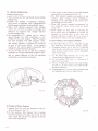
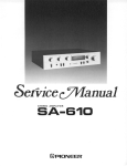
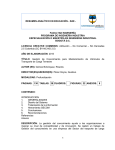
7.2 .MOTOR OPERATION
1 Motor Construction
1. These motors are
flat type 8-pole 6-coil
slotless
Hall motors.
the 3-phase Y-connected windings,
each motor is equipped with 3 phase-detector
Hall elements positioned at intervals 60' apart.
3. These Hall elements generate Hall voltages
which vary in level according to strength and
direction of magnetic flux changes induced
by the rotating rotor.
4. An independent FG magnet used to detect
speed changes has been positioned on the
outside of the rotor magnet. This FG magnet
has been designed with 200 magnetic poles,
and rotates opposite a printed coil mounted
on part of the circuit board. As the magnet
rotates an AC current signal is generated and
is used for speed detection purposes.
5. As can be seen in Fig. ?-1,the rotor magnet
generates an 8 polar trapezoidal magnetic wave,
and by phase additions of the coil switching
waveforms a even torque is obtained.
2. Besides
Fis.
If the power
is then turned on, the Hall element
outputs will be as indicated in Fig. 7-8.
4. The Hall element outputs are applied to the
position signal forming circuit (PA200bA),
resulting in the switching of the current flowing through the drive coils.
5. These Hall element outputs are generated by
the rotational action of the rotor as shown
in Fig. 7-9.
6. These signals are thus used in switching the
drive circuit (also in PA2005A) to change the
3.
direction of current flow in the coils, and
thereby determine whether an N or S pole is
generated, or whether the coil is switched off.
ln actual rotation, this happens as follows.
7. As the robor side of coil Lo becomes a south
pole, that of Lu becomes north, and L., neutral.
8. Repulsion between the S pole at La and the
rotor S pole, and attraction between the Ls N
pole and the rotor S pole exert a propulsive
force on the rotor.
9. As the rotor tums through 15" of arc, the
output from the Hall elements changes.
10. Ls now enters OFF state, Lc becomes a N
pole, and Lo a S pole.
11. The L6 N pole now attracts the rotor S pole,
and the La S pole attracts the rotor N pole.
Rotation continues.
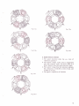
12. Correspondences between rotor positions and
coil polarities are shown in Fig. 7-3, a-f..
7 -1
2. Principle of Motor Rotation
1. Assume that the rotor has stopped at the position as shown in Fig. 7-2.
2.In this position, Hall element HA is located
half way between an S pole and N pole on the
rotor, while HB and HC are opposite an N pole
and S pole respectively.
a
HB
Fig.7 -2
@
Hs
a
He
Fig.7-3-a
z2
HB
Fig. 7-3.e
a
Hs
Fis. 7-3-f
HB
Fis. 7-3-b
3. Speed Detection Section
1. The speed detection plate has one rows of
"detection patterns. "
2. The bottom surface of the rotor is magnetized
with 200 magnetic poles, and these rotate at a
short distance above the speed detection plate.
3. The output voltage from the detection patterns
has a frequency of 55.5H2 at 33-1/3 rpm, and
of. 7 \Hz at 45 rpm.
4. The signal is supplied to IC PA2004.
zt
Hg
a
Fig. 7-3-c
Fig. 7-3-d
7.3 OPERATION OF THE PDlOO3
IC
(OSCILLATOR STAGE)
1. Once the power supply is turned on, the quartz
crystal oscillator generates a 6744kHz signal.
2. The frequency of this signal is reduced to
1.5kHz (714096 division) by frequency divider I.
Part of the resultant signal is passed via the
x'tali RC switching circuit and applied to
frequency divider II. The other part of the
signal is applied to frequency divider selector II.
3. The 1.5kHz signai applied to frequency divider
II is further divided into a 750H2 signal, and
applied to frequency divider selector I where
the signals are converted into sampling pulses
for phase comparison purposes in PA2004.
33rpm 27.78H2
45rpm
37.5H2
(In both cases, the pulse width is 0.66?ms).
4. Frequency divider selector II converts signals
from frequency divider I into pulse signals for
the stroboscope lamp drive circuit.
33rpm
45rpm
(In both
cases,
55.5H2
71.OHz
the pulse width is again 0.667ms).
NOTE:
This IC (PD1003) is not employed
PL-200 and PL-225 models.
in the motor of
the
7.4 OPERATION OF THE
PA2OO4 IC
(coMPARATOR CONTROL)
1. Signals from the frequency generator in the
motor rotation ass'y are changed into 50% duty
square wave signals by the waveform rectifier.
The frequencies at this stage are thus,
33rpm
45rpm
55.55H2
75Hz
of the output is divided by Vz in the FF
circuit, and subsequently applied to the FV
converter circuit along with the other part of
the output formed in step 1 above, thereby
forming the FV converter gate pulse sigaals.
2. Part
3. The output from the FV converter is applied to
buffer amplifiers
I
and II.
4. The buffer amplifier I output is compared with
the reference voltage in buffer amplifier III, and
then applied to the output compose circuit.
of the sampling pulses from
the PD1003 IC with the FV converter output
occurs in buffer amplifier II, with the resultant
output being applied to buffer amplifier IV.
6. The output from buffer amplifier IV is also
applied to the output compose circuit.
7. This output compose circuit consists of a lowpass filter (cut-off frequency 23H2, cut-off slope
-6dB/oct.) which serves to eliminate the carrier
component in the output of buffer amplifier II
5. Phase comparison
(phase comparison).
8. This final output signal is then passed onto the
comparator control stage of the PA2005 IC for
comparison with the reference voltage.
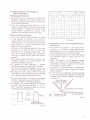
7.5 OPERATION OF THE PA2OOs
IC
F F-r
(DRIVE CONTROL)
. Stroboscope Pulse Circuit
1. The platter has only a single row of stroboscopic
markings. Switchover for 45 and 33 rpm is effected by changing the frequency of the pulse
to the stroboscopic lamp.
2. From the Frequency Divider Selector I, a frequency of either 7\Hz (for 45 rpm, representing
1/80 of 6000H2) or 55.5H2 (for 33 rpm, representing 1/108) is obtained and supplied to the
transistor that drives the stroboscopic lamp.
will further
accelerate the
the reverse direction. This
turntable rotation in
is.known as "reverse run-away."
4. To prevent this from happening, a Reverse
Rotation Prevention circuit has been included.
5. This Reverse Rotation Prevention circuit consists of two flip-flops and AND gates See Fig. 7-4.
6. The input for this circuit is derived from the
Hall element position detection signals processed
in the Reverse Rotation Prevention circuit.
7. As long as the platter is rotating in the proper
direction, this pulse enters in the order B - A C, and no "reverse" command is generated.
8. If, however, the platter rotates in the reverse
direction, the pulse order becomes A - B - C,
and a corrective command is given to the Forward/Reverse Command Circuit.
R
1
o
1
A
1
o
1
cl
o
o
A
I
o
o
o
o
o
o
o
I
o
1
1
o
o
1
o
o
o
o
o
I
o
I
o
o
o
C
o
o
o
I
I
o
1
(J
1
SO
a
o
Truth table
o Comparator Control
and Forward/Reverse Com-
mand Circuit
Two inputs are supplied to the Control Comparator: a) a 4V reference voltage from the voltage stabilizer; and b) the output from the active
filters, which serves as the detection signal.
2. If the turntable rotates faster than rated speed,
the detection signal is higher than the 4V
1.
reference.
3. When this happens, the Comparator Control
sends a command to the Forward/Reverse Com-
mand Circuit, telling it to apply a reverse torque
to the motor to slow it down.
4. Conversely, if
rotation is below rated
^turntable
speed, the detection signal voltage will be below
the 4V reference.
5. In this case, the Comparator Control indicates
to the Forward/Reverse Command Circuit that
forward torque must be applied to the motor to
aicelerate it.
Area
of
5
Operating point at zero load
+
FFz
AND
n
o
2oul
.I
turned slowly in the reverse direction by hand, a
forward torque will be applied until the platter
stops, reverses its rotation and reaches rated
speed in the proper direction.
2. If, however, the rotational speed in the reverse
direction is in excess of 33 or 45 rpm, the
Forward/Reverse Command Block may "misread" this as simply excessive speed ("overrun")
and apply a reverse torque until rated speed is
S
F]
l )rrt
.I
to the direction of rotation. If the platter is
A
at
u
1. This motor operates indiscriminately in regard
FFr
()
I
o Reverse Rotation Prevention
attained.
3. This reverse torque
Ti
FF:
AN I)
(
S
Output
V18...Voltageat
V19...Voltageat
0
lnput voltage differential between
pin (18)
pin (19)
pins (18) and (19)
Fis.7-5
L--)
t r-
R
Forced Forward
Rotation at 0 ourtput
Fig. 7 -4
17
o
Drive Circuit
1. The signals employed in the switching of Q2 Q7 in Fig. 7-6 are generated by 3 Hall elements,
and applied to terminals a, b, and c via the
position signal formation circuit.
2. "lhe phase of these step waveform signals is
displaced by 120' from each other.
3. When the step waveform signals at position I
in Fig. 7-7a are applied to the drive circuit
terminals a, b, and c, the potential at terminal
a will be lowered, resulting in Q2 being turned
on. The potential at terminal b will be raised,
resulting in Q6 being turned oh, but the
potential at terminal c will remain at the
reference level voltage (the bias settings for
Q4 and Q7 have been designed to prevent
these 2 transistors from operating when a
reference level voltage is applied).
4. Vcc will thus be applied across the Q2 - coil
La - coil Le - (2) - Q6 route, thereby producing an S polarity in La, and an N polarity
in
the magnetic field is generated, the rotor
will commence to rotate. After the rotor turns
5. Once
through 15' , the signals at position II in Fig. 7-7b
will be applied to terminals a, b, and c, thereby
resulting in a change in the flow routes of the
drive currents. After the rotor turns through
another 15', the signals shown at position III
in Fig. 7-?-c will be applied, again resulting in
changes in flow routes of the drive currents.
For every 15' that the rotor turns through, the
flow routes for the drive currents will change
as shown in Figs. 7-7d, 7-7e, and 7-'7f, finally
6.
returning to the routes shown in Fig. 7 -7 a again.
A control voltage generated by the forward/
reverse direction discriminator indicator circuit
is applied to the control input terminal, thereby
controlling the flow of current in the coils.
Ls.
Fis.7-6
1A
-+#
\-/
o
-l+l
o2 -=a
l\)+
a->
Q3
n.
rs
ueJ O CH
IS L€ ool €
Control
{]
d
LA i
t:
ttr1
I
o---_l
ta
1 'u,=/
01 lltsh
a,l
input
NN
Fig.7
-fi\._)
o
Lz --R 03 -R
{ tl.t
o{o
a:>
.\
.LH
86€
Os
Control
i
-7 -a
ILJ
t-
J,
nput
GND
Fig.7-7-b
{{
02 --@, Q3
l- tl
o oo-.1
O
| .--
15ru
Control
-e f,4
I
\_->
-l
I
-----,-,=--1
,:1-@
Or
ll
o,t ll
I L,/
',F"^Fui"
I
J'
input
.^a
1
+
cNn
Fig.7 -7-c
[
02 --@ Q3
lI
o
\.J
l o"-j
f,rZ
,-.
r-ff
l-
O CH
06 t-C
l5
Control
i nput
ILJ
Ql
GNI)
Fig.7
-7 -d
vcc
t5,
Qz
-R
e rboJ
t |
tr|#A
i',ft{
15
1rffi
v
O ail
ru
'/">
06€
Jlt
r-4
I
I7
d6D
Ir
3 ll Kb.
-:-lA\
I{ a,/
Control
tr
+
.1,
input
GND
Fig.7-7-e
VCC
-tK
o
/->
82
03rc ^l
l-
bo-{
J5 L€
Control
i nput
r-ll
t4
O
I|
l9
\
LaB
f-
j
+l
I
,:l*Lc 3*ll',Hbif,
-lA'
br
Itl
C
.--
Nt)
Fig.7
-7
-t
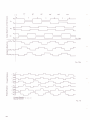
19
45"
I
P
co)
Her
E
q)
UJ
HA
Hez
(U
I
o
U'
E
o
Hs X:;
q)
(u
=f
o
f
o
Hcr
Hc
Hcz
,' L4(H41+Hg2)
E
L
o
q)
(o
3
c)
'; LB(HB1+Hs2)
o
oE
o
oLc(HA2+Hc1)
Fis. 7-8-b
C
o
(u
o
E,
E
(!
3
o
u-
co
F
(El
5
G
o)l
u,
b
<u
rH
Al
IH
lH
Bl
H
IH
\H
EE
Rotation E + A .*.
A* B--*l
Rotation
Reverse
For'ward
Fis. 7-9
\
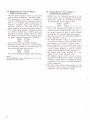
7.6
BLOCK DTAGRAM (PL-200, PL-255)
NOTE:
The DD motor employed
models operates
in the PL-200 and PL-300
in much the same way as the DD mo-
tor in the PL-255 and PL-400 models.
for details.
See
pp.14-20
z
^
Vcc
9
SCHM ITT
TB IGGE R
BUFFEB
AMPl
REFERENCE
VOLTAGE
T
€
I
+B
16.5V
DR IVE R
POSITION
S
IGNAL
FORMATION
FWD/REW
DIRECTION
B
EVE RSE
ROTATION
P REV ENTION
COMPARATOR
+B
t7
16.5V
UICK STOP
TIMING
CONTROL
*
VOLTAGE
STABILIZE
R
Vcc
t5
2'.1
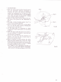
8. MECHANISM
DESCRIPTIONS
8.1
PL.2OO MECHANISM OPERATING
The PL-200 is equipped with auto-return only.
Fig. 8-1 shows the PL-200 in the stationary state
with the tonearm back in the arm rest.
Gear A
Motor
Microswitch
Lever B
Fig.8-1
*
START OF PLAY
1. When the tonearm is moved across to the disc,
the PU plate located below in the arm base is
also moved.
2. Lever A is moved over by pin A connected to
this PU plate, resulting in lever B being unlocked.
3. At the same time that lever B is unlocked, the
microswitch is turned on (power on), and the
motor commences to rotate.
Lever A
Microswitch
Fig.8-2
Fis.8-3
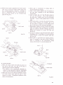
*
AUTO-RETURN
the stylus enters the disc lead-out groove
and the auto-return detector mechanism is
activated, the claw of the detector mechanism
catches the projecting part of gear B on the
center shaft, resulting in gears A and B engaging
each other and gear B consequently rotating
in the counter clockwise direction.
2. Plate B is then shifted across towards the tonearm due to the gloove in the underneath of
gear A.
3. The edge of plate B pushes against lever C to
force the arm elevation upwards.
4. Plate B continues to shift across to push against
pin B on the PU plate, thereby returning the
tonearm back to the arm rest.
5. At this stage plate B commences to return
towards the center shaft guided by the groove
in gear A.
6. When the edge of plate B separates from lever C,
the arm elevation is lowered to drop the tonearm back into the arm rest.
7. And at the same time that the tonearm is returned to the arm rest, pin A returns lever A
back to the stationary state.
8. Plate B continues to move towards the center
shaft and pushes against pin C on lever B. Lever
B thus switches the microswitch off (power off),
and is then locked by lever A, thereby bringing
a complete operation cycle to an end.
*For details on the operational principles involved in the auto-return detector mechanism,
refer to the PL-516 Service Manual (ART-2T9).
1. When
Motor
Gear B
Gear A
Fis.8-4
Fis. 8-5
8.2 PL-4OO MECHANICAL OPERATION
* LEAD.IN
B rotates counter-clockwise, lever B
is moved forwards by spring action (in the direction of the arrow). And while plate A is being
moved across to the tonearm, lever B is being
pulled forwards to reach the state shown in
Fig. 4. The slider stops at the position selected
by the size selector. And although cam B continues to press against lever A, excess stroke
action by lever B at this time is absorbed by the
flexible spring.
When plate A moves towards the tonearm, cam
C fixed to the right hand of plate A presses
against cam D attached to the arm base (Fig. 810). Cam D thus rotates in the clockwise direction, thereby lifting the arm elevation, and
resulting in the raising of the tonearm.
8. Just before plate A completes its movement
across towards the tonearm, pin C of the PU
plate is clasped by the lead-in latch due to the
action of the hole in the sub-panel unit (Fig. 810). And when plate A commences to return
towards the center shaft, the PU plate moves
in a clockwise direction, thereby carrying the
tonearm across to the record.
9. When plate A commences to return towards the
rear, lever B is also pulled back by the action
of spring A, and stops when it meets the slider.
Cam B is also brought to a stop by this action
(Figs. 8-9, 11).
6. When cam
Fig. 8-6 shows the PL-400 in the stationary state
with the motor stopped and the tonearm upon
the arm rest.
L. When the START/STOP button is pressed,
lever D will be shifted towards the left by spring
B of lever F (Fig. 8-6).
2. Pin A located above lever D then presses against
plate C, thereby unlocking plate C from lever C.
And once lever C is separated from the microswitch the power for the motor will be turned
on (Fig. 8-7).
3. The plate C plate spring will also press against
lever A, thereby repelling the cam A detector
assembly (Figs. 8-7, 8).
4. Once the motor commences to rotate, the motor
pinion gear (gear B) catches the claw of the
detector assembly, and gear A and gear B engage
each other, resulting in gear A rotating in the
counter-clockwise direction (Fig. 8-8).
5. And since gear A commences to rotate, plate A
moves towards the tonearm, resulting in the
plate A projection (point A) being pressed
against cam B to turn the plate in the counter-
clockwise direction (Fig. 8-g).
Plate A makes a round trip by tracing the heart
shaped groove formed in the underneath of
gear A.
Lever A
Plate A
Detector ass'y
Plate C
Spring A
Lever D
Sub panel
LeverD
./
Spring
B
I
LeverC
Microswitch
Fis. 8-6
led in by the lead-in latch also
stops when it meets cam B (Fig. 8-11). Then
when plate A returns further, the lead-in latch is
opened by the action of the sub-panel unit hole,
resulting in the release of pin C on the PU plate
(Fig. 8-13).
The position where the PU plate stops corresponds to the postion set by the disc size
10. The PU plate
12. Then when plate A returns further towards the
center shaft, cam B is rotated clockwise by the
projection on plate A, and lever A is returned
towards the rear. Lever A and cam B are thus
returned to their original positions to permit
the tonearm free movement.
13. Furthermore, plate C presses pin A on lever D
across to the left hand side, thereby returning
Iever D back to its position prior to starting.
14. Lever A is set by striking against the projection
selcor.
11. As plate A returns towards the center shaft, cam
D is released from cam C, thereby lowering the
arm elevation to commence record play.
Pin E(PU
plate)
on gear A.
ptate C
Lever A
Pin A(lever D)
Plate C(plate spring)
Lever B
Lever A
Lever C
Microswitch
Fig.8-7
Cam C
D.D. motor
Gear
D
?).
Detector
assembly
Lever A
Plate A
Gear A
Spring A
Fig.8-8
Fig.8-9
15. When the PU plate completes the lead-in opera-
tion, pin E of the PU plate rotates lever E in
the counter-clockwise direction, resulting in
Iever C separating from the microswitch to
leave the motor power on for continued disc
play (See Fig. 8-7).
3.
When gear
A
commences
to rotate, plate A
moves towards the tonearm.
4. Cam C then presses against cam
D attached to
the arm base, resulting in the arm
elevation
being raised.
5. Cam C pushes
pin C of the PU plate across to
the arm rest position. Pin E also moves at
the same time, rotating lever E in the clockwise
direction. Lever E thus pushes lever C to the
right.
6. Just before plate A reaches the end of its movement across towards the tonearm, pin C of
the PU plate is clasped by the lead-in latch
due to the action of the sub-panel unit hole.
7. When plate A starts to return towards the center
shaft, the lead-in latch holding pin C is opened
again by plate D, thereby releasing pin C to
permit the tonearm to return the arm rest
(fig. 8-13).
8. As cam C returns to the left hand side, cam D
disengages cam C, resulting in the arm elevation
being lowered to drop the tonearm back into
the arm rest.
9. When plate A approaches its original position,
plate C is pushed to the left by cam C fixed to
plate A, resulting in the microswitch being
turned off by lever C to turn the motor off .
PU plate
Pin C
Lead in reach
Cam C
Cam D
Fis. 8-10
Cam B
Pin C
Lead in reach
Plate A
.t 'r
r
Cam C
Fis.8-12
Cam D
Fis. 8-1 1
..
.f
\..\
\..
I
O AUTO-RETURN
1. When the stylus enters the lead-out groove at
the end of the disc, the end of the paly
PU plate C
is
detected by the detector assembly.
Lead in reach
*For details on the operational principles
involved in the auto-return detector mechanism,
refer to the PL-516 Service Manual (ART-279).
2. When the claw of the detector assembly catches
the motor pinion gear (gear B), gear A commences to rotate. Subsequent operation is the
same as during lead-in.
Cam C
Fis. 8-13
O REPEAT OPERATION
When the repeat button is pressed during record
play, the control base unit will be as shown in Fig.
9-2. Lever D will thus not to move any further
left than a pre-determined position.
After the end of the "lead-in" operation, the
"auto-return" operation commences when the
end of record play is reached.
1. At the start of the auto-return operation, cam
A rotates to move plate A towards the right.
2. Cam C pushes against cam D to raise the arm
elevation.
3. Cam C pushes pin C of the PU plate to the right.
4. When cam C reaches across to the right hand
side, the lead-in latch grasps pin C of the PU
plate, resulting in the tonearm being moved
across to the disc.
The main difference here to the auto-lead-in
operation is that pin A of lever C pushes plate
D when the repeat button is pressed, resulting
in the lead-in latch not being opened by plate
D (as occurs during auto-return). Consequently,
the tonearm does not stay at the arm rest, but
proceeds to move back towards the record for
repeated play. Subsequent operations are the
same as during normal autolead-in operation.
Push switch (repeat switih)
Spring B
Fis.8-14
.
INTERRUPTION OF RECORD PLAY
1. Press the START/STOP button.
2.Pin A of lever D pushes plate C to the right,
resulting in the plate C plate spring forcing
lever A upwards. And this in turn repels the
detector assembly.
3. Subsequent steps are the same as steps 3 to 10
described under auto-return.
O MANUAL START AND STOP
1. When the tonearm is lifted ovei to the disc by
hand, pin E of the PU plate rotates lever B in
the clockwise direction. Lever B is thereby
disengaged from lever C, switching the microswitch on to start the motor.
2. When the tonearm is lifted off the record during
play and returned to the arm rest, pin E of the
PU plate rotates lever B in the clockwise direction and this lever thus presses against lever C.
When lever C then makes contact with the
microswitch (pressing the microswitch pushbutton), th motor is subsequently turned off.
Fis. 8-15
Pin A(lever C)
Plate D
Lead in reach
Plate D
)
Cam C
Fig. 8-16
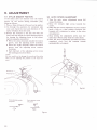
9. ADJUSTMENT
9.1 STYLUS DESCENT POSITION
If the stylus does not descend onto the lead-in
groove on the record during automatic play,
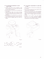
9.2 AUTO RETURN ADJUSTMENT
1. Turn the auto return adjustment
adjust as follows:
1. Place a 30cm (12-inch) LP record on the platter.
2.
2. Go through the operation for automatic play
once and check the level and direction of the
stylus'deviation from the norm.
3. Return the tonearm to the arm rest with one
hand, and then adjust the stylus descent-position
by turning the adjusting screw in the adjusting hole using the screwdriver.
o When the stylus descends outside the lead-in
groove, turn the adjusting screw clockwise.
. When the stylus descends inside the lead-in
groove, turn the adjusting screw counterclockwise.
. Each half-turn of the adjusting screw moves
the starbing point about 6mm.
screw full
around clockwise.
Move the tonearm right across towards the
center.
3. When the auto return adjustment screw is turned
back a little at a time counter clockwise, the
tonearm will commence to return to the outer
circumference.
Stop turning the adjustment screw once the
stylus tip is 00mm away from the center shaft.
5. Once the above adjustment procedure has been
completed check that the tonearm returns
4.
automatically as designed.
NOTE:
Be uery careful not to damage the record and the stylus
when you are adjusting the position of the stylus descent.
Adjusting hote
Fis. 9-2
Stylus descends outside
the groove
E_
5fou\
Stylus descends inside
the groove
ffi
E'
f0\
Fig.9-t
2B
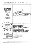
9.3
9.4 D.D. MOTOR ADJUSTMENT
D.D. MOTOR ADJUSTMENT (PL-300
(PL.2OO AND
AND PL-400)
1. Connect the TP3 and TP4 terminals of the
control assembly to the inputs (CH1 and CH2)
PL-255)
1. Turn the power on and start the turntable plat-
of a dual trace oscilloscope.
2. Turn the power on and start the turntable platter rotating.
3. Adjust VR1 and VR2 of the control assembly
so that the rising edge of the waveform on TPB
lies inside the square waveform on TP4 as shown
in Fig. 9-4.
4. This adjustment is performed from the direction
of the turntable base plate as shown in Fig. 9-3.
5. Adjust VR1 for 33rpm speed, and VR2 for
45rpm.
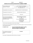
2. Turn the speed adjustment knob around to the
mechanically center position.
3. Adjust VR1 and VR2 in the control assembly
so that the stroboscope appears to be stationary.
Again this adjustment is performed from below.
4. Adjust VR1 for 33rpm speed, and VRZ for
Fig. 9-3
TPl
TP2
10v
_-'u
Fig. 9-4
ter rotating.
45rpm.
5.
As can be seen in Fig. 1, the rotor
magnet
generates an 8 polar trapezoidal magnetic
wave, and by phase additions of the coil switching waveforms a even torque is obtained.
Fig. 9-5