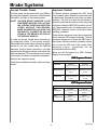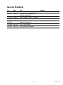
1
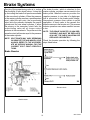
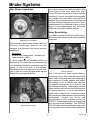
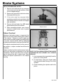
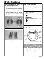
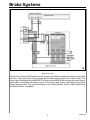
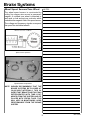
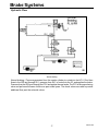
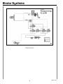
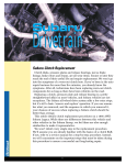
Technicians
Reference
Booklet
Brake Systems
Series Module
Module 501
MSA5P0170C
© Copyright 2002
Subaru of America, Inc.
All rights reserved. This book may not be reproduced
in whole or in part without the express permission of
Subaru of America, Inc.
Subaru of America, Inc. reserves the right at any time
to make changes or modifications to systems,
procedures, descriptions, and illustrations contained
in this book without necessarily updating this
document. Information contained herein is considered
current as of March 2002.
© Subaru of America, Inc. 2002
3
Brake Systems
4
Brake Systems
Table of Contents
Introduction ........................................................................................................................ 8
General Overview .............................................................................................................. 8
General ABS Operation .................................................................................................... 19
Teves Mark IV with ABS/TCS .......................................................................................... 24
Vehicle Dynamic Control (VDC) ....................................................................................... 42
Sensors ........................................................................................................................... 45
Service Bulletins .............................................................................................................. 53
501 Module Service Tech TIPS ........................................................................................ 54
March 2002
5
Slide Sequence
Slide No.
1
2
3
4
5
6
7
8
9
10
11
12
13
14
15
16
17
18
19
20
21
22
23
24
25
26
27
28
29
30
31
32
33
34
35
36
37
38
39
40
41
42
43
44
45
46
47
48
49
50
51
Description
Page No.
Title Slide (Brakes System)
Created By
Teaching Aids
Introduction
Title Slide (General Overview)
Dual Diagonal Brake System (artwork)
Front Disc Brake
Rear Disc Brake
Front Disc Brake
Depressing Caliper Piston (older)
Hill Holder TM System
Pressure Hold Valve
Clutch Pedal Free Play
Clutch Lever Free Play
Adjusting the PHV
Master Cylinder Cross Section
Master Cylinder
Reed Switch Schematic (artwork)
Reed Switch Construction
Typical Proportioning Valve
2001 Legacy Rear Drum Brake and VDC Model (artwork)
2001 Legacy Rear Disc Brake Model (artwork)
Brake Booster
Booster Check (artwork)
Measuring Rotor Thickness (artwork)
Measuring Rotor Run out
Rotor Resurfacing
Piston Removal
Removing Pistons
Front Caliper Lubrication Points
Pads Assembled
Locating Brake Vibration Source (artwork)
Self-Adjuster Operation (Brakes Applied)
Drum Brake Lubrication Points
Legacy Parking Brake System
Title Slide (General ABS Operation)
Hydraulic Control Unit
Valve Relay Circuit
Motor Relay Circuit
Speed Sensor Operation (artwork)
Speed Sensor Components
Title Slide (Teves Mark IV with ABS/TCS)
Master Cylinder - Traction Control
Teves Mark IV Hydraulic Control Unit
Brake Pedal Stroke Sensor
Wheel Speed Sensor / Tone Wheel
Combination Meter
TCS Off Switch
ABS/TCS Control Module
Normal Braking (artwork)
ABS Braking Pressure Drop (artwork)
8
9
9
9
10
10
10
11
11
11
12
12
12
12
13
13
13
14
14
15
15
15
16
16
17
17
17
17
18
18
19
19
20
21
22
22
24
24
25
25
25
25
26
26
27
28
March 2002
6
Slide Sequence
Slide No.
52
53
54
55
56
57
58
59
60
61
62
63
64
65
66
67
68
69
70
71
72
73
74
75
76
77
78
79
80
81
82
83
84
85
86
87
88
89
90
91
92
Description
Page No.
ABS Braking Pressure Hold (artwork)
ABS Pressure Rise (artwork)
TCS Logic-Engine Control (artwork)
TCS Logic- Engine Control & Brake Control (artwork)
TCS Logic / Wheel Slip Recognition (artwork)
TCS Logic - One Wheel Slip (artwork)
TCS Logic - Two Wheel Slip (artwork)
TCS Logic - One Wheel Slip (artwork)
TCS Logic - Two Wheel Slip (artwork)
TCS Pressure Rise (artwork)
TCS Pressure Hold (artwork)
TCS Pressure Drop (artwork)
TCS Logic / Valve Control (artwork)
Title Slide (Vehicle Dynamic Control (VDC))
VDC Logic Chart
Understeer
Oversteer
Cornering Force
Oversteer While Accelerating
Understeer While Accelerating
Oversteer While Braking
Understeer While Braking
Title Slide (Sensors)
Steering Position Sensor
Steering Position Sensor Construction
Steering Position Sensor Waveform
Degrees of Turn
Wheel Speed Sensor
Yaw Sensor
Yaw Sensor (artwork)
Hydraulic Control Unit
VDC CM Connector
VDC CM Location
Pressure Reducing Mode (artwork)
Pressure Holding Mode (artwork)
Pressure Increasing Mode (artwork)
Pressure Increasing Mode (artwork)
Pressure Holding Mode (artwork)
Pressure Reducing Mode (artwork)
Copyright
The End
29
30
31
31
32
32
32
33
33
34
35
36
37
42
42
42
42
42
43
43
44
44
45
45
45
45
45
46
46
46
46
47
47
47
48
48
48
49
49
March 2002
7
Brake Systems
Introduction
General Overview
This Technicians Reference Booklet introduces
the brake systems used on Subaru vehicles. It
covers the component operation, troubleshooting, diagnosis, and service precautions and
procedures. This information is presented with
special emphasis on procedures, tools and
materials unique to the Legacy, Forester and
Impreza vehicles. Subaru-specific servicing
procedures and precautions are also included
in this booklet.
SUBARU Brake Systems Overview
6
The text and illustrations are derived from and
follow the classroom lectures and slide
presentations. They are intended to supplement
and reinforce classroom instruction and to serve
as a home-study reference source. Lists of
applicable Service Bulletins, important notes and
cautions, and Special Tools are included within
this booklet. Pages for noting additional
Diagnostic Tips and Notes are also provided.
Dual diagonal brake system
All Subaru vehicles are equipped with a dual
diagonal brake system. A master cylinder feeds
a crisscross hydraulic circuit consisting of a
primary circuit and a secondary circuit. Braking
force is transmitted to the right-front and the
left-rear brakes by the primary system. Braking
force is delivered to the left-front and the right-rear
brakes by the secondary system. This safety
feature not only provides even braking, but also
provides balanced braking in the event of failure
of one of the circuits.
Technicians Worksheets are to be completed
during the hands-on lab work segments of the
Brake System Module.
Always refer to the appropriate model year
Subaru Service Manual and the Applicable
service bulletins for all specifications and
detailed service procedures.
5
March 2002
8
Brake Systems
Disk Brake Overview
All disc brakes are self-adjusting and feature a
single or dual piston in a free floating caliper
design. The type of caliper used depends on
model type and trim level.
9
Front Disk Brakes
Disk brakes on Subaru vehicles feature selfadjusting, single piston or dual piston, freefloating calipers that slide on pins. The calipers
are designed to provide easy access to the pads.
The pads are equipped with wear indicators that
begin to squeal when the pad wears to a specific
minimum pad thickness. Ventilated front rotors
keep the brakes cooler. Solid rotors are used with
rear brakes.
7
Front Disk Brake
Front disc brakes feature a ventilated disc which
has high heat dissipation and superb braking
stability. Due to the nature of their design, disc
brakes quickly restore the original braking
performance when wet.
When the brake pedal is depressed and
hydraulic pressure is supplied to the caliper, the
piston slides through a flexible square-cut seal
to push against the inside pad, and the caliper
body is pulled against the outer pad. As the pad
wears, the piston slides farther through the seal
to take up the slack.
When the brake pedal is released, the piston is
pulled away from the pad by the force of the seal
returning to its normal square shape.
8
Rear Disc Brake
Rear disc brakes features are similar in a solid
rotor design brake mechanism.
All current Subaru vehicles equipped with a rear
drum brake system will be of the self adjusting
type.
March 2002
9
Brake Systems
Pad Replacement Procedures
Hill Holder (TM) system
When replacing disc brake pads, follow the steps
listed below. Always replace the pads in sets of
four. Remember that the brakes are free-floating;
guide pins and the sliding surfaces of the pad
and clips must be properly lubricated, and
sufficient clearance must exist between the top
pad and the holder.
1) Remove the lock pins and raise the caliper
2) Remove the pads
11
3) Loosen the bleeder screw and push the
piston in the cylinder
4) Install new pads
5) Reinstall the caliper and the brake cable
NOTE: IF THE PAD FITS TIGHTLY IN THE PAD
HOLDER, RAPID PAD WEAR CAN OCCUR.
Hill-HolderTM system
Subaru brake systems also incorporate a unique
Hill-Holder (TM) system. It is standard equipment
on all 1990 to 1994 Legacy vehicles with manual
transmissions. The system prevents rollback
when the vehicle is starting on an uphill grade.
The heart of the Hill-Holder (TM) system is the
pressure hold valve (PHV). Connected in series
with the primary circuit, it works in conjunction
with the clutch pedal via a linking device to hold
pressure in the primary hydraulic brake circuit.
10
Depressing caliper piston (older)
Because the new pads will be thicker than the
old ones being replaced, the caliper piston needs
to be retracted in the caliper body. Before pushing
the piston back into the caliper, loosen the
bleeder screw. After the pads are replaced and
the brake calipers are reassembled, depress the
brake pedal several times to take up the slack
between the caliper piston and the brake pad
before test-driving the vehicle.
12
Pressure hold valve
March 2002
10
Brake Systems
When the vehicle comes to a stop on an uphill
grade greater than or equal to 3 degrees, a push
rod inside the PHV retracts when the clutch is
depressed. This permits a ball in the PHV to roll
backwards to seal hydraulic pressure in the
primary circuit. When the brake pedal is released,
the pressure trapped in the primary circuit by the
ball holds the vehicle stationary. When the clutch
pedal is released, the push rod extends once
more to unseat the ball and release the hydraulic
pressure.
14
NOTE: THE PHV IS NON-SERVICEABLE AND
MUST BE REPLACED AS A UNIT.
Clutch lever free play
Hydraulic Servicing Precautions
When servicing any of the hydraulic components,
follow these precautions carefully.
1) Use DOT 3 or DOT 4 brake fluid.
2) Clean internal brake components with
alcohol. External brake components may be
cleaned with brake clean type solvents.
3) Use specified lubricants.
4) Do not hone aluminum cylinders.
15
5) Do not use silicone type brake fluids
Adjusting the PHV
13
Clutch pedal free play
On 1990 to 1994 Legacy vehicles with manual
transmission, check the operation of the HillHolder (TM) system at every maintenance
interval by road-testing the vehicle. If the system
does not function properly, first verify the clutch
pedal free play. Check it at either the pedal or
the lever and adjust as necessary. If the vehicle
will not hold on an incline of 3 degrees or greater,
tighten the adjusting nut of the pressure hold
valve cable until proper operation is achieved. If
the brakes release late, loosen the adjusting nut
on the PHV.
NOTE: CONFIRM PROPER OPERATION BY
ROAD-TESTING THE VEHICLE.
The PHV can also be adjusted to operate on very
small inclines. Install a shim (P/N: 725807000)
between the frame and the support to raise the
front of the PHV.
NOTE: ONLY ONE SHIM IS ALLOWED.
March 2002
11
Brake Systems
Master Cylinder
A sealed reservoir tank has been adopted to
extend the service life of the brake fluid
18
Reed Switch Schematic
16
Master cylinder cross-section
The master cylinder used in all current Subaru
vehicles is divided into two chambers: Primary
hydraulic chamber (Chamber P) and Secondary
hydraulic Chamber (Chamber S).
19
Reed Switch Construction
17
Master Cylinder
The primary chamber supplies working pressure
to the right-front and left-rear hydraulic circuits
while the secondary chamber supplies working
pressure to the left-front and right-rear hydraulic
circuit. In the event of a hydraulic circuit failure,
the vehicle will still maintain some braking
performance.
March 2002
12
Brake Systems
Brake Fluid Indicator
Typical Proportioning Valve
Components consist of a reed switch which
mounts below the brake fluid reservoir and a
permanent magnet housed in a float inside the
brake fluid reservoir. When activated, the reed
switch completes a ground circuit to turn on the
brake warning lamp in the combination meter.
Under normal conditions, the float remains above
the reed switch, and the magnetic force from the
permanent magnet in the float is unable to
activate it. As the brake fluid drops, and falls
below a specified level, the reed switch will be
activated by the permanent magnet, completing
the circuit to ground. The brake warning light may
light intermittently if the vehicle tilts or swings
excessively.
NOTE: WHEN THE BRAKE WARNING LIGHT
ILLUMINATES:
20
Typical proportioning valve
Another hydraulic component in Subaru brake
systems is the proportioning valve.
1) The Day Running Lights will not
illuminate.
2) The Traction Control System will not
operate.
(95 LEGACY WITH TEVES MARK IV ABS/TCS)
21
2001 Legacy Rear drum brake and VDC model
22
2001 Legacy Rear disc brake model
March 2002
13
Brake Systems
The job of the proportioning valve is to reduce
the possibility of rear wheel lockup. It does this
by controlling the brake fluid pressure available
to the rear wheel cylinders. When the pressure
in the master cylinder reaches a predetermined
point, called the split point, the proportioning
valve limits the pressure between the master
cylinder and the rear wheel cylinders. If either
the primary or the secondary circuit fails, the
proportioning valve will no longer control
pressure to the rear wheels. The pressure in the
operative circuit will remain equal to the pressure
in the master cylinder.
NOTE: SPLIT POINTS MAY VARY DEPENDING
ON VEHICLE TYPE AND MODEL YEAR.
ALWAYS REFER TO THE APPROPRIATE MY SERVICE MANUAL FOR THE
CORRECT SPLIT POINT SPECIFICATIONS.
The brake booster, which is attached to the
master cylinder, provides vacuum assist to the
brake pedal. Manifold vacuum provides the
negative pressure to one side of a diaphragm
that is connected to the brake pedal linkage.
Atmospheric pressure then assists in pedal
application. A check valve in the vacuum line
traps the vacuum in the booster unit. This ensures
booster operation even when manifold vacuum
is low.
NOTE: THE BRAKE BOOSTER IS NON-SERVICEABLE AND MUST BE REPLACED
AS A UNIT. THE CHECK VALVE MAY BE
REPLACED SEPARATELY.
Check the booster operation by following the
steps listed below:
Brake Booster
24
Booster check
23
Brake booster
March 2002
14
Brake Systems
Disc Brake Inspections
Rotor runout should be measured within 0.20
inches (5mm) of the outer edge of the rotor.
Consult the service manual for the acceptable
runout limit. If runout is not within the acceptable
limit, machine the rotor within specifications if
possible. Do not machine a rotor to less than the
minimum thickness stamped on the rotor. Rotor
parallelism must be measured at three or more
places. If your measurements vary more than
.0008 inch, machine or replace the rotor.
Rotor Resurfacing
25
Measuring rotor thickness
If you find it necessary to service vehicle rotors,
Subaru recommends on-the-car rotor resurfacing
equipment.
When servicing disc brakes, always make the
following inspections: Measure the pad
thickness, rotor thickness, rotor runout, and rotor
parallelism.
Parallelism
thickest rotor measurement – thinnest rotor
measurement < .0008
A visual inspection will probably suffice for
determining the remaining pad thickness, but
rotor thickness should be measured near the
center of the rotor with a micrometer.
Specifications for rotor thickness may vary from
year to year, so consult the appropriate service
manual for proper specifications.
26
Measuring rotor runout
27
Rotor resurfacing
Due to the nature of brake system design,
resurfacing rotors with off-the-car type brake
lathes often results with customers returning to
with complaints of brake vibration and judder.
Resurfacing rotors on-the-car can minimize
comebacks because the rotor and hub are
serviced as an assembly. In this manner, stacked
tolerances that may have occurred with time can
be compensated for. If you a resurfacing a
Subaru with a trapped rotor, on-the-car service
will save the time and expense of wheel bearing
replacement. Subaru has tested and
recommended a rotor matching system by
PROCUT. Rotor matching refers to servicing the
rotor and hub as an assembly. The PROCUT
PFM 900 offers quick and accurate setup while
proving optimum rotor finish for brake pad breakin.
March 2002
15
Brake Systems
ROTOR RESURFACING NOTES:
1. Remove rotor and remove any corrosion
on the inner and outer hat surfaces. (Only
on non-trapped design).
2. Remove any corrosion on the hub surface
that mates with the rotor.
3. If the rotor must be removed after
resurfacing, mark the rotor and hub so that
their relative positions remain unchanged
after installation.
28
4. Remove all metal chips from ABS wheel
speed sensors and tone wheels.
Piston removal
5. When reinstalling wheels, use a torque
wrench to tighten wheel nuts to proper
specifications.
Caliper Overhaul
Whenever the brake system is inspected, the
inspection should include checking the condition
of the calipers. Calipers in need of repair can
cause numerous brake problem including pulling
to one side, reduced pad life, ABS not operating
at optimum performance, and loss of brake fluid.
If the calipers are determined to be the cause of
the problem, a caliper overhaul would then be
necessary.
Caliper overhaul includes replacement of seals,
dust boots, and rubber components of the slide
mechanism. Caliper bores with minor corrosion
may be cleaned up with a caliper hone. Deep
pitting will require replacement of the caliper
housing.
29
Caliper disassembled
NOTE THE FOLLOWING PRECAUTIONS WHEN
OVERHAULING DISC BRAKES ON A SUBARU
VEHICLE:
1) Use compressed air to gradually force the
piston out of the cylinder.
2) To avoid injury, keep your fingers away
from the piston when forcing it out of the
cylinder.
3) Avoid scratching the cylinder wall or the
piston.
March 2002
16
Brake Systems
AFTER DISASSEMBLING THE CALIPER, MAKE
THE FOLLOWING INSPECTIONS:
1) Check the caliper body for damage.
2) Check the piston for wear and damage.
3) Upon reassembly, use only specified
greases and compounds.
Brake System Inspection
To determine whether the source of a brake
vibration is in the front brakes or in the rear
brakes, road-test the vehicle. Follow the steps
listed below:
4) Bleed the brake system after servicing.
NOTE: USE ONLY DOT 3 OR DOT 4 BRAKE
FLUID.
32
Locating brake vibration source
30
Rear Drum Brakes
Front caliper lubrication points
31
Pads assembled
33
Self-adjuster operation (brakes applied)
Subaru vehicles equipped with rear drum brakes
will be of the self-adjusting type. When the drum
brake is activated, the self-adjuster lever travel
increases. When the brake shoes are contacting,
the self-adjusting lever rotates the adjuster
assembly's screw to lengthen the whole
assembly. This maintains clearance between the
shoes and the drum to a specified value.
March 2002
17
Brake Systems
NOTE: THE SELF-ADJUSTING MECHANISM
OPERATES EACH TIME THE BRAKE
PEDAL IS DEPRESSED. THE SCREW
ROTATES ONLY WHEN CLEARANCE
IS EXCESSIVE.
7) Measure the drum diameter. Note that
specifications may change from year to
year. Consult the appropriate service
manual for specifications.
8) If drums are unevenly worn, resurface
them on a brake lathe.
NOTE: ALWAYS RELEASE THE SELF-ADJUSTING MECHANISM BEFORE REMOVING THE DRUM.
9) Replace the cotter pins, lock tabs, or stake
nuts with new ones.
34
35
Drum brake lubrication points
When servicing rear drum brakes, follow these
precautions:
1) Pull the drum if necessary.
2) Replace large and small springs in their
proper positions (large spring on top, small
spring on bottom).
3) Apply specified grease to lubrication
points on the backing plate.
Legacy parking brake system
The Legacy, Forester, and Impreza use a rear
drum type parking brake system. The drums are
located in the rear disc rotors. The mechanically
operated parking brake engages the shoes
against the drums. When the parking brake lever
is released, the shoe return spring disengages
the shoes from the drum.
4) Apply specified grease to the contact
surface of the self-adjuster and shoe and
to the inside wheel cylinder boot.
5) If the wheel cylinder is scratched, replace
it. Wheel cylinders cannot be honed.
6) Wheel cylinder piston seats are not
replaceable separately. The seals are
available with replacement pistons only.
March 2002
18
Brake Systems
Parking Brake Servicing Procedures
Refer to the appropriate Subaru service manual
for detailed servicing procedures.
NOTE: EACH BRAKE SHOE PARKING BRAKE
LEVER MUST MOVE SMOOTHLY. DO
NOT CONFUSE LEFT AND RIGHT
PARKING BRAKE LEVERS AND
STRUTS.
Test drive the vehicle to confirm proper operation
of the brake system and also to "break-in" the
parking brake linings. Maintain 15 to 20 MPH and
lightly pull on the parking brake lever and
release. Repeat at least five times.
General ABS Operation
The purpose of ABS is to allow the driver to
maintain directional control over the vehicle
during extreme braking conditions. This is
accomplished by using a Hydraulic Control Unit,
Anti-lock Brake S ystem C
Control Module, GSensor and wheel speed sensors to determine
impending wheel lockup. If wheel lockup is
detected, hydraulic pressure to the affected
wheel is modulated until wheel slip is controlled.
CAUTION: DO NOT "LOCKUP" THE REAR
WHEELS, ALWAYS PULL THE LEVER SLOWLY.
DO NOT PERFORM THIS OPERATION ON PUBLIC ROADS.
Check the parking brake for the proper
adjustment. Always use the appropriate service
manual for exact specifications. The first step is
to adjust the clearance between the shoes and
drum by rotating the star-wheel located on the
parking brake assembly. Then, pull up on the
parking brake lever and count the number of
notches until resistance is felt. If the count is out
of specs, adjust the length of the parking brake
cable with the adjusting nut located on the
parking brake lever.
37
Hydraulic control unit
The HCU contains an electrically controlled
motor plunger/pump. Depending on the ABS
model, Subaru HCU's will have three, four, eight,
or ten electrical solenoids to help control brake
application when ABS is active. To activate a
solenoid, it must receive battery voltage and a
ground signal. The solenoids receive battery
voltage from a valve relay. The valve relay is
energized by the HCU. The HCU energizes the
valve relay at vehicle start up and remains
energized unless the ABSCM detects a problem
in ABS circuitry. Upon seeing a fault, the ABSCM
de-energizes the valve relay interrupting the
power supply to the solenoids in the HCU. Under
normal driving conditions, the valve relay
remains energized at all times. You can see this
information displayed on your Select Monitor.
(Only on ABS systems that are Select Monitor
compatible).
March 2002
19
Brake Systems
38
Valve relay circuit
The solenoids receive their ground signal directly from the ABSCM. In actual operation, the solenoid
receives constant power and the ABSCM activates a solenoid by providing a path to ground.
March 2002
20
Brake Systems
39
Motor relay circuit
The HCU’s on Subaru ABS systems contain a pump motor which operates a hydraulic pump inside
the HCU. The pump motor has a constant ground and receives power from a motor relay. The
motor relay is energized by the ABSCM. The only time the ABSCM will energize the motor relay is
when ABS is controlling the braking action of the vehicle and during a self-check during initial
vehicle start and drive. This can be observed on your Select Monitor. (Only on ABS systems that
are Select Monitor compatible)
March 2002
21
Brake Systems
Wheel Speed Sensors/Tone Wheel
NOTES:
The wheel speed sensor is constructed by
coiling fine copper wire around a permanent
magnet. A notched tone wheel is attached to
each axle or hub and acts as a reluctor which
modulates the magnetic field of the speed sensor.
The voltage and frequency signals correspond
the speed the individual wheels.
40
Speed sensor operation
41
Speed sensor components
NOTE: SUBARU RECOMMENDS THAT THE
BRAKE SYSTEMS BE FLUSHED AT
30,000 MILE INTERVALS. THIS INSURES THAT BRAKE FLUID THAT HAS
DETERIORATED WITH TIME IS REMOVED FROM THE SYSTEM AND REPLACED WITH FRESH FLUID. THIS
WILL HELP IN MAINTAINING GOOD
PERFORMANCE FROM THE BRAKE
SYSTEM.
March 2002
22
Brake Systems
ABS Quick Tips
Bosch Nippon ABS2SL
No long term memory
Nippon ABS2E
Long term memory
Electrical faults indicated by ABS
warning lamp
Electrical faults indicated by ABS
warning lamp
Does not communicate with Select
Monitor
Does not communicate with Select
Monitor.
Stores up to three trouble codes.
Special bleeding procedure.
Only stores 1 trouble code at a time.
Select Low Control
Special bleeding procedure.
Codes retrieved by grounding diagnostic
terminal and observing ABS warning
lamp.
Select Low Control.
Codes retrieved through cutout in rug
underneath passenger seat.
Teves Mark IV
Combines ABS and TCS
Long term memory
Sequence control
ABS 5.3
Electrical faults indicated by ABS
warning lamp.
Electrical faults indicated by ABS or TCS
warning lamp
Long term memory
Stores up to three trouble codes
Communicates with SMI or SMII
Special bleeding procedure
Special bleeding procedure
Communicates with SMI or SMII
Select Low Control
Select Low Control
Codes retrieved by grounding diagnostic
terminal and Observing TCS warning
lamp or by using SMI or SMII.
Codes retrieved by grounding diagnostic
terminal and Observing ABS warning
lamp or by using SMI or SMII
Separate ABS and TCS sequence control
procedures.
ABS 5.3i
Electrical faults indicated by ABS
warning lamp
Sequence control
VDC
Electrical faults indicated by ABS or VDC
warning lamp.
Long term memory
Long term memory
Stores up to three trouble codes
Stores up to three trouble codes
Special bleeding procedure
Special bleeding procedure
Communicates with SMII
Communicates with SMII
Select Low Control
Select Low Control
Separate ABS and VDS sequence
control procedures
Codes retrieved by grounding diagnostic
terminal and Observing ABS warning
lamp or by using SMII
Special procedure to calibrate steering
sensor
Sequence control
March 2002
23
Brake Systems
Teves Mark IV with ABS/
TCS
In 1995 Subaru introduced the Teves Mark IV
Hydraulic Control Unit that featured both an antilock brake system and a traction control system.
The two systems are interdependent and both
systems will go into fail-safe if a common
component or signal malfunctions. ABS/TCS is
available on front wheel drive, U.S. and Canada
spec 5MT or 4EAT equipped vehicles only.
Manual transmission vehicles with TCS cannot
be equipped with a hill-holder because of
hydraulic piping layout and TCS operation.
Hydraulic Control Unit
The hydraulic control unit assists in the control
of brake fluid flow during normal braking, ABS
operation, and TCS operation. The HCU contains
10 solenoid valves that route the brake fluid. They
are:
1. Input Front Right (IFR) normally open
2. Input Front Left (IFL) normally open
3. Input Rear Right (IRR) normally open
4. Input Rear Left (IRL) normally open
5. Output Front Right (OFR) normally closed
6. Output Front Left (OFL) normally closed
7. Output Rear Right (ORR) normally closed
Master Cylinder
8. Output Rear Left (ORL) normally closed
The master cylinder inside diameter is 1 1/16
inches. There are 4 ports located on the master
cylinder. (primary, secondary and 2 for ABS/TCS).
9. Special Valve #1 (SV1) normally open
10. Special Valve #2 (SV2) normally open
During normal braking and ABS operation SV1
and SV2 remain off (open). During TCS
operation, SV1 and SV2 will turn on (closed).
Each solenoid has a check valve connected in
parallel with it to aid in the flow of fluid. (The
solenoid design restricts flow.)
The HCU contains a motor sensor which
monitors the rotation of the motor armature and
produces a sine wave (2 volts peak to peak),
which is sent to the ABS/TCs control module to
judge motor operation.
43
Master cylinder - Traction control
A tandem diaphragm booster is used which is 8
and 9 inches in diameter. The pushrod of the
booster protrudes inside the master cylinder,
resulting in zero clearance between the master
cylinder and the booster.
The motor and pump assembly is used to modify
brake fluid pressure during ABS operation. The
motor and pump assembly activate during TCS
and the pressure rise mode of ABS. Pressure
generated while in the rise mode is used to apply
the brakes. The motor and pump assembly will
also activate during TCS operation, supplying
brake fluid pressure to the left front and /or right
front calipers, which is decided by the control
module, to control wheel slip.
The pressure switch monitors the pressure
generated by the master cylinder. The control
module uses the signal from the switch to
suspend TCS operation if any pressure is
generated by the master cylinder. (brake applied
by the driver)
March 2002
24
Brake Systems
The motor relay controls motor operation via the
control module.
Wheel Speed Sensors
46
44
Wheel speed sensor / tone wheel
Teves Mark IV Hydraulic Control Unit
The valve relay controls the power supply to the
ten solenoids inside the hydraulic control
module.
Brake Pedal Stroke Sensor
Wheel speed sensors and tone wheels, which
are located at each wheel, generate a sine wave
which is sent to the control module. The control
module then calculates the wheel speed for each
individual wheel.
Combination Meter
45
Brake pedal stroke sensor
A brake pedal stroke sensor is located at the top
of the brake pedal. The sensor produces signals
for the ABS/TCS control module when the brakes
are applied. It consists of six 100 ohm resistors
wired in series, a movable contact, and five
stationary contacts. The normal resistance at rest
is 100 ohms. The operating range of the sensor
is 100-500 ohms. The sensor allows the control
module to monitor how much effort is applied to
the brake pedal. In operation , the control module
will cancel TCS operation if any effort is applied
to the brake pedal. (backup for the pressure
switch)
47
Combination meter
The combination meter contains three lamps that
will give information about ABS/TCS system to
the driver. They are the ABS warning lamp, the
TCS warning lamp, and the TCS operation lamp.
The ABS warning light will illuminate:
1. During the light check cycle
2. During a D-check or read memory check
3. Sequence control
4. ABS malfunction
March 2002
25
Brake Systems
The TCS warning light will illuminate:
ABS/TCS Control Module
1. During the light check cycle
2. TCS malfunction
The TCS operation lamp will illuminate:
1. During the light check cycle
2. While TCS is controlling the acceleration
of the vehicle
TCS Off Switch
49
ABS/TCS control module
The ABS/TCS control module controls the
application of ABS and TCS vehicle functions. It
also networks with the engine control module
during TCS operation and networks with the
transmission control module during ABS
operation.
48
TCS off switch
There is a TCS off switch located in the dash to
the left of the steering wheel. The TCS off switch
is used to disengage the TCS system under
conditions that it is being triggered frequently.
(space saver spare tire being used) The TCS off
switch is also used during the air bleed
procedure.
Alight in the TCS off switch will illuminate under
the following conditions:
1. During the light check cycle
2. When the TCS off button has been
pushed (momentary contact switch)
3. Excessive TCS operation in a short
amount of time (driver continually trying
to free the vehicle from snow or mud. This
can overheat the brake pads and rotor. As
a result. The control module will shut down
the TCS to allow brake components to
cool.)
March 2002
26
Brake Systems
Hydraulic Flow
50
Normal braking
Normal braking – Pressure generated from the master cylinder is routed into the HCU. Fluid then
flows to the IRR and through SV1, pressure from SV1 is routed into the IFL and applies the brake.
Pressure from the IRR goes through the PCV and applies the rear brake. The PCV is the proportioning
valve and performs the same function as past model years. The check valves are used to provide
additional flow past the solenoid valves.
March 2002
27
Brake Systems
51
ABS braking pressure drop
ABS Braking Approaching Wheel Lock-up – Pressure drop occurs first. IFL closes, preventing
master cylinder pressure from reaching the caliper or wheel. The ABS/TCS control module
immediately memorizes the position of the brake pedal from the brake pedal sensor. The OFL
opens and reduces the pressure in FL caliper, by providing a passage to the master cylinder reservoir.
The lock-up is avoided and the wheel accelerates, the ABS/TCS now enters pressure hold mode.
March 2002
28
Brake Systems
52
ABS braking pressure hold
Pressure Hold – The IFL and OFL close, trapping the remaining pressure in the brake caliper.
Wheel speed is then reevaluated, and the ABS/TCS will enter pressure rise or drop, depending on
whether the wheel need to accelerate or decelerate.
March 2002
29
Brake Systems
53
ABS pressure rise
Pressure Rise – The OFL remains closed, IFL opens and the brake pedal begins to move toward
the floor. The motor pump assembly activates and pressurizes the hydraulic circuit from the caliper
to the master cylinder. At this point the pump output pressure is approximately 150 kgcm2, which
overcomes the approximately 100kgcm2 produced by the master cylinder, and pushes the pedal
away from the floor and applies the brake. The pump will continue to operate until the pedal is
repositioned to the memorized location which occurred in the pressure drop mode. This action
produces brake pedal kick back. Pressure drop, hold, and rise will continue until the wheel speed
is nominal.
March 2002
30
Brake Systems
TCS Operation
55
54
TCS Logic - Engine Control & Brake Control
TCS Logic - Engine Control
TCS improves and controls acceleration on low
friction road surfaces, or when one of the driving
wheels unloads creating wheel slip. The fuel and
brake systems are used together to eliminate
wheel slip. The objective of the TCS system is
to supply the maximum driving torque to the front
wheels. Monitoring of the driving torque is
accomplished by observing wheel speed sensor
signals. The ABS/TCS control module compares
the front wheels (driving) to the rear wheels
speed, which represents true wheel speed, to
judge wheel slip. Wheel slip is more critical in
certain driving conditions than in others.
Example: Initial acceleration (high slip) and
cruising (low slip), the ABS/TCS control module
has nine different programs that will respond to
various driving conditions.
Traction control is accomplished by a networking
of control units. The ABS/TCS control module
recognizes wheel slip, picks the program that will
best begin control of it and sends a signal to the
fuel injection control module. Fuel injectors are
cut (turned off) to reduce engine torque. This is
called “engine control”. This action alone would
produce a vibration at low vehicle speeds while
in low gear ratios. To counteract the vibration, the
ABS/TCS control module sends signals to the
HCU to apply the brake while the engine is
recovering from fuel cut. The braking action
called “brake control”, slows down a slipping
wheel or wheels. Combined with engine control,
provides a constant decrease in driving torque.
Torque, which would otherwise transmit to the
slipping wheel, in the case of a one wheel slip,
is now transferred through the differential to the
wheel with traction. This is called a “limited slip
differential effect”.
March 2002
31
Brake Systems
Logic
One-Wheel Slip
56
57
TCS Logic / Wheel slip recognition
The ABS/TCS control module recognizes one
or two wheel slip under 31mph. This aspect of
TCS concentrates on acceleration. When vehicle
speeds are above 31mph, the TCS will focus on
vehicle stability in the event of wheel slip and
therefore will only recognize two wheel slip. The
amount of fuel cut during engine control is
dependant on vehicle speed and wheel slip
speed. Large wheel slip conditions result in large
fuel cuts while small wheels slips result in small
fuel cuts. Initial acceleration wheel slips are not
recognized until wheel slip speed is 5mph.
Vehicle speeds over 31 mph have slightly higher
wheel slip speed recognition.
TCS Logic - One wheel slip
TCS engine control is determined by the severity
of the wheel slip and the number of wheels
slipping. One wheel slip results in a large fuel
cut at first and is quickly reduced to restore torque
to the wheel with traction. This concentrates on
acceleration.
Two-Wheel Slip
Braking control during TCS operation results in
approximately 10% of the total available braking
force of the vehicle. Braking control initially
occurs just after fuel cut and logic braking control
wheel slip recognition parallels fuel cut wheel
slip recognition until 31mph. Vehicle speeds over
31 mph result in higher braking control wheel slip
recognition than engine control. The means that
braking control will be delayed to give engine
control time to reestablish control. This results in
improved vehicle stability.
58
TCS Logic - Two wheel slip
Two wheel slip results in a large fuel cut at first
and increases if the slip does not decrease and
decreases if the wheel slip decreases. This
concentrates on stability.
TCS brake control is also determined by the
severity of wheel slip.
March 2002
32
Brake Systems
NOTES:
59
TCS Logic - One wheel slip
The maximum amount of braking during TCS
operation is approximately 10% of the total
braking ability of the vehicle.
60
TCS Logic - Two wheel slip
March 2002
33
Brake Systems
TCS Hydraulic Control
When TCS activates, SV1 and SV2 turn on and close, isolating the rear calipers so that no braking
can occur in the rear. The motor and pump assembly turn on, pressurizing the brake circuit. The
IFR will close if a left wheel slip is detected, allowing no braking on the FL. The IFL will close if the
right wheel slip is detected, allowing no braking on the FL.
61
TCS pressure rise
Two wheel slip will result in both inlet valves remaining open, allowing braking on the FR and FL
wheels. When braking occurs during one wheel slip, the driving torque that would otherwise go to
the slipping wheel is transmitted through the differential to the wheel with traction, creating a Limited
Slip Differential Effect
Effect. During two wheel slip, the objective is to slow down both wheels, reducing
driving torque.
March 2002
34
Brake Systems
62
TCS pressure hold
March 2002
35
Brake Systems
63
TCS pressure drop
March 2002
36
Brake Systems
64
TCS Logic / Valve control
March 2002
37
Brake Systems
Teves Mark IV Diagnostics
Access Trouble Codes
Diagnostics begin with verifying the complaint
and doing a thorough visual inspection . The
following steps should help you diagnose most
complaints that did not cause an ABS or TCS
warning light to illuminate. This can also help you
in cases that no trouble code was stored in the
memory of control unit.
Trouble codes can accessed with your NSM or
by using the diagnostic connector located under
the dash to the right of the steering wheel.
1. Check battery voltage to insure battery is
fully charged
2. Inspect tires for proper sizing. Ideally, all
four tires should be of the same make,
model, and size
3. Check air pressure in all four tires and set
to specifications.
4. Check all four wheels for excessive brake
drag. This could indicate sticky pistons or
caliper slides.
5. Inspect all hydraulic lines for leaks and
make needed repairs.
NOTE: THE NEW SELECT MONITOR IS THE
PREFERRED METHOD FOR ACCESSING TROUBLE CODES AND INITIATING
OTHER SERVICE PROCEDURES.
MORE INFORMATION ON USING THE
DIAGNOSTIC CONNECTOR CAN BE
FOUND IN THE BRAKES SECTION OF
THE 1995 LEGACY SERVICE MANUAL
SERVICE MANUAL.
If codes are stored, trouble shoot according to
the diagnostic charts in the service manual.
Perform the clear memory procedure with the
NSM.
Test drive vehicle and verify that ABS and TCS
warning lamps remain off.
Verify that no additional trouble codes have been
stored.
6. Inspect wheel bearings for excessive play
and make needed repairs.
7. Top off brake fluid level if necessary.
8. Perform ABS and TCS sequence control
procedures and compare your results to
specifications in service manual.
March 2002
38
Brake Systems
Sequence Control
On Subaru vehicles equipped with ABS/TCS,
there is a procedure called sequence control that
can be performed. Sequence control has two
basic functions. Sequence control allows the
technician to check the mechanical condition of
the pump and solenoids inside the ABS/TCS
hydraulic control unit. The second function is to
help purge air from ABS/TCS hydraulic control
unit during a brake bleeding procedure.
There are two separate sequence control
procedures that can be used on ABS/TCS
equipped vehicles. The first procedure allows you
to check the ABS side of the system while the
second procedure allows you to check the TCS
side of the system. Both sequence control
procedures can be accomplished with the NSM.
Go to section 4-4 page [W20D0] and [W20F0] of
the 1995 Legacy service manual for instructions
on how to perform sequence control with the
Select Monitor. Below are normal results for ABS
and TCS sequence control.
ABS Sequence Control Specifications
Initial Value
When Decompressed
When Compressed
Front Wheel 3,432 kPa (35 kg/cm2, 498 psi)
490 kPa (5 kg/cm2, 71 psi) or less
981 kPa (10 kg/cm2, 142 psi) or more
Rear Wheel 3,432 kPa (35 kg/cm2, 498 psi)
490 kPa (5kg/cm2, 71 psi) or less
981 kPa (10 kg/cm2, 142 psi) or more
Initial Value
When Compressed
When Decompressed
Front Left
Wheel
490 kPa (5 kg/cm2, 71 psi)
or less
1,471 kPa (15kg/cm2, 213 psi)
or more
490 kPa (5 kg/cm2, 71 psi)
or less
Front Right
Wheel
490 kPa (5 kg/cm2, 71 psi)
or less
1,471 kPa (15 kg/cm2, 213 psi)
or more
490 kPa (5 kg/cm2, 71 psi)
or less
TCS Sequence Control Specifications
March 2002
39
Brake Systems
Air Bleed Procedures
NOTE: TO THOROUGHLY BLEED THE HYDRAULIC SYSTEM THE FOLLOWING
PROCEDURE MUST BE STRICTLY FOLLOWED. SKIPPING STEPS MAY RESULT IN AIR REMAINING IN THE SYSTEM. THE BRAKE PEDAL SHOULD BE
DEPRESSED SLOWLY WITH AT LEAST
3 SECONDS BETWEEN EACH APPLICATION. FOR CONVENIENCE AND
SAFETY, IT IS ADVISABLE TO HAVE
TWO TECHNICIANS WORKING
6. Bleed air through RF and LF calipers by
operating brake pedal. This is the same
procedure as step 2 above. Repeat steps 2
thru 6 until air no longer comes out.
7. Bleed air through RR and LR calipers by
operating brake pedal. This is the same
procedure as step 3 above.
8. Operate Right Front Outlet valve and Left
Rear Outlet valve to bleed air from their
specific circuits.
a) Press TCS OFF switch while depressing
brake pedal
1. Start air bleed operation with the Select
Monitor. Refer to section 4-4 [W19C0] or
[W19D0} of the 1995 Legacy service manual.
b) Make sure ABS warning light illuminates
c) Depress and release brake pedal slowly
10 times or more while depressing the
TCS OFF switch.
2. Bleed air through RF caliper by depressing
the brake pedal.
a) Fit one end of a vinyl tube onto the air
bleeder and keep the other end
submerged in a container with brake fluid.
b) Slowly depress the brake pedal and keep
it depressed. Then, open the air bleeder
to discharge air together with the fluid.
Release air bleeder for 1 to 2 seconds.
Next with the bleeder closed, slowly
release the brake pedal. Repeat these
steps until there are no more air bubbles
in the vinyl tube.
3. Bleed air from suction pipe through RF
caliper.
a) Open the air bleeder.
b) Keep depressing the TCS OFF switch for
20 second or more. Ensure no air comes
out from bleeder.
c) Close the air bleeder.
4. Bleed air through LF caliper by following step
2 above.
5. Bleed air from suction pipe through LF caliper
by following step 3 above.
9. Operate Left Front Outlet valve and Right
Rear Outlet valve to bleed air from their
specific circuits.
a) Press TCS OFF switch while depressing
brake pedal.
b) Make sure TCS warning light illuminates.
c) Depress and release brake pedal slowly
10 times or more while depressing the
TCS OFF switch.
NOTE: WHILE PERFORMING STEPS 8 AND 9,
AIR WILL BE RELEASED THROUGH
BRAKE FLUID RESERVOIR. THE OPERATIONS IN STEPS 8 AND 9 CAN BE
SWITCHED WITH EACH OTHER BY
DEPRESSING THE BRAKE PEDAL
WHILE DEPRESSING THE TCS OFF
SWITCH. EACH TIME THE TCS OFF
SWITCH IS DEPRESSED WITH THE
BRAKE PEDAL DEPRESSED. YOU
WILL SWITCH FROM ONE DIAGONAL,
(RF/LR) TO THE OTHER. (LF/RR)
10. With all procedures completed, fully depress
the brake pedal for approximately 20 seconds
to make sure there are no leaks in the entire
system.
11. Turn off the ignition switch.
12. Perform TCS sequence control.
March 2002
40
Brake Systems
13. Check the pedal stroke
NOTES:
a) While the engine is idling, depress the
brake pedal with a force of 110 lbs. and
measure the distance between the brake
pedal and steering wheel. With the brake
pedal released, measure the distance
again. The difference between the two
should be less than 3.740 inches. If the
distance exceeds specifications there still
may be air in the system.
14. Turn off ignition switch
15. Disconnect the select monitor
16. Add brake fluid to the required level of the
reservoir.
17. Test drive vehicle to ensure brakes provide
normal braking action on all four wheels
without dragging and uneven braking.
March 2002
41
Brake Systems
Vehicle Dynamic Control
(VDC)
Understeer is the result of a movement of the
vehicle where the driver’s intent is to make a
change in direction and while the steering wheel
is turned the vehicles direction changes little or
not at all. This is due to the front wheels slipping
across the road surface.
66
68
VDC Logic
Vehicle Dynamic Control or VDC combines Antilock Brakes, Traction Control and new vehicle
stability logic. The VDC system is designed to
keep the vehicle behavior in the driver’s
expectations when the actual vehicle behavior
may divert from what is expected.
Oversteer
Oversteer is the result of a movement where the
driver’s intent is to make a change in direction.
While the vehicle is doing so, the amount of
change is too great. This is due to the rear wheels
slipping across the road surface.
69
67
Cornering force
Understeer
VDC operation comes into use during periods
of driving when understeer or oversteer
conditions are encountered. Four wheel TCS
and ABS functions become active any time the
VDC CM determines they are needed.
Slip occurs whenever a vehicles’ cornering force
is less than it’s centrifugal force. The cornering
force is a combination of vehicle weight, tire
quality, design, and the road surface.
There are two ways to control slip: Produce a
force or yaw moment of the reverse direction in
the case of oversteering or produce a yaw
moment of the same direction as the turning
direction in the case of understeering.
March 2002
42
Brake Systems
These two slip controls can be utilized by three
systems acting independently or together.
They are:
•
Brake control by utilizing the hydraulic
control unit
•
Engine torque control with the ECM
•
Torque distribution control for the front
and rear wheels working with the TCM.
Oversteering and understeering can occur with
the accelerator depressed, brake pedal
depressed or with no pedal depressed. In each
case, the response from the VDC CM is
customized to the driving conditions of the
vehicle and the resulting vehicle response.
71
Understeer While Accelerating
Understeering while depressing the
accelerator pedal.
Correction required: Stop the front wheels from
slipping outward and return the front of the
vehicle to the intended path.
Actions taken:
1. Apply weak brake force to the front inner
wheel.
2. Apply strong brake force to the rear inner
wheel.
3. Release the connection of the transfer to
increase driving force distribution ratio to
the rear wheels.
70
Oversteer While Accelerating
4. Decrease engine torque by fuel cut.
Oversteering while depressing the
accelerator pedal
Correction required: Stop the rear wheels from
slipping outward, and maintain the front of the
vehicle towards the intended path.
Actions taken:
1. Apply strong brake force to the front outer
wheel.
2. Apply weak brake force to the rear outer
wheel.
3. Increase the transfer clutch engagement.
4. Decrease engine torque by fuel cut.
March 2002
43
Brake Systems
72
73
Oversteer While Braking
Understeer While Braking
Oversteering while applying the
brake.
Understeering while applying the
brake.
Correction required: This is the same situation
as the ABS system operating and understeering
condition is needed.
Correction needed: This is the same as the ABS
system operating and oversteering condition is
needed.
Actions taken:
Actions taken:
1. Loosen the brake for the front inner wheel.
1. Loosen the brake for the front outer wheel.
2. Loosen the brake for the rear inner wheel.
2. Loosen the brake for the rear outer wheel.
If the braking force applied by the driver is
insufficient, VDC operates creating hydraulic
pressure by the pump to increase the braking
force on the front outer wheel.
If the braking force supplied by a driver is
insufficient, VDC operates creating hydraulic
pressure by the pump, to increase the braking
force on the rear inner wheel.
March 2002
44
Brake Systems
Sensors
Steering Position Sensor
77
Steering position sensor waveform
75
Steering position sensor
This sensor is located under the steering wheel
and is indexed with it to create signals as the
steering wheel is turned.
The first is made of a large reluctor with nine hall
elements. The positioning of the reluctor over the
hall elements creates signals that are sent to the
VDC CM control unit that when combined with
the second sensing element communicate the
position of the front wheels. The output of the
steering wheel position is displayed in 2.5degree increments. The full range of steering
wheel detection is 720 degrees.
76
78
Steering position sensor construction
The internal make up of the sensor consists of
two sensing elements.
Degrees of turn
360 degrees to the right which shows up as
positive and 360 degrees to the left shows up as
negative. The movement of the second sensing
element tells the control unit to go negative or
positive and communicates the number of
steering wheel revolutions.
March 2002
45
Brake Systems
Yaw Rate Sensor- Detects the rotating
velocity of the vehicle body during turning.
79
Wheel Speed Sensor
Wheel Speed SensorSensor-Detects wheel speed by
each wheel.
81
Yaw Sensor (artwork)
Lateral G Sensor- measures the centrifugal
force exerted on the vehicle.
These two sensors are housed in a single unit
and is located in the center console near the
hand brake.
80
Yaw Sensor
82
Hydraulic Control Unit
Brake pressure Sensor- Measures the
estimated braking force applied to each wheel
applied by the driver.
March 2002
46
Brake Systems
Hydraulic operation during
ABS and or VDC operation
when the brake pedal is
depressed.
Pressure reducing mode
83
VDC CM connector
Input signals from the VDC CM determines the
calculated driving force applied to the wheels.
85
Pressure reducing mode
84
VDC CM location
Signals from the TCM- Using front to rear split
information combined with VDC CM information
determines the driving force of the engine or
braking applied to the wheels.
When the wheels are about to lock due to the
braking action, instructions are issued from the
control module and power is supplied to the EV
and AV solenoid valves. The EV valve closes,
cutting off the master cylinder pressure and
wheel cylinder pressure. The AV valve opens
reducing the wheel cylinder pressure and power
is simultaneously supplied to the motor at this
time. The brake fluid temporarily is collected in
the reservoir and is sucked out by the self sucking
pump, passed through the damper chamber,
where pulsations are absorbed and is then
returned to the master cylinder side. In this way;
a pressure-reducing control is performed with the
fluid pressure in the wheel cylinder side being
completely separated from that in the master
cylinder.
March 2002
47
Brake Systems
Pressure holding mode
TCS operation and or VDC
operation when the brake
pedal is released
Pressure increase mode
86
Pressure holding mode
When the optimum wheel cylinder fluid pressure
is obtained, power is supplied to the solenoid
valve (EV valve) according to VDC CM
instructions. The valve closes, cutting off the
master cylinder pressure and the wheel cylinder
side.
Pressure increasing mode
88
Pressure increasing mode
When the wheels slip while driving, or slip occurs
while the vehicle is turning, instructions are
issued by the VDC CM and the VDC/TCS control
is initiated. Power is supplied to the USV and
HSV valves. The USV valve closes and the HSV
valve opens at the same time. Power is also
supplied to the motor, and the brake fluid in the
master cylinder reservoir is sucked through the
HSV valve by the self sucking pump, passing
through the EV valve and pressurizing the wheel
cylinder side.
m
edo
87
Pressure increasing mode
When the wheel cylinder pressure needs to be
increased, power to the solenoid valves are
turned off according to VDC CM instructions,
resulting in normal braking conditions. Pressure
is then applied by the master cylinder.
March 2002
48
Brake Systems
Pressure holding mode
Pressure reducing mode
89
90
Pressure holding mode
Pressure reducing mode
When the optimum wheel cylinder fluid pressure
is obtained, power is supplied to the EV valve
according to VDC CM instructions. The USV
valve, HSV valve and motor power supply
conditions are not changed. The EV valve is
closed, cutting off the brake fluid pressurized by
the self -sucking pump. The brake fluid
pressurized by the self-sucking pump is then
passed through the USV relief valve and returned
to the master cylinder.
When the wheel cylinder fluid pressure must be
reduced, power is supplied to the EV valve and
AV valve according to VDC CM instructions. The
USV valve, HSV valve and motor power supply
conditions are not changed. The EV valve is
closed and the AV is opened. The wheel cylinder
fluid pressure is discharged to the master
cylinder side through the reservoir and HSV
valve, reducing the pressure on the wheel
cylinder side. The brake fluid pressurized by the
self-sucking pump is passed through the USV
relief valve and returned to the master cylinder.
March 2002
49
Brake Systems
VDC light operation
VDC Diagnostics
During the light check cycle all lights will
illuminate for a short time.
VDC diagnostics begin with verifying the
complaint and doing a thorough visual
inspection. The following steps should help you
diagnose most complaints that did not cause an
ABS or VDC warning light to illuminate. This can
also help you in cases that no trouble code was
stored in the memory of control unit.
•
VDC Operation (Car with tire tracks)
•
VDC
•
VDC OFF
•
ABS
1. Check battery voltage to insure battery is
fully charged
During VDC operation the VDC Operation light
(car with tire tracks) will blink.
During TCS operation the VDC Operation light
(car with tire tracks ) will be on solid.
2. Inspect tires for proper sizing. Ideally, all
four tires should be of the same make,
model, and size
A malfunction with the VDC system will illuminate
just the VDC light.
3. Check air pressure in all four tires and set
to specifications.
A malfunction with the ABS will illuminate the
ABS and VDC light.
4. Check all four wheels for excessive brake
drag. This could indicate sticky pistons or
caliper slides.
A malfunction with the ECM or TCM will
illuminate the VDC Off light.
5. Inspect all hydraulic lines for leaks and
make needed repairs.
A fuse placed in the VDC slot in the fuse box will
illuminate the VDC Off light.
6. Inspect wheel bearings for excessive play
and make needed repairs.
7. Top off brake fluid level if necessary.
8. Perform ABS and VDC sequence control
procedures and compare your results to
specifications in service manual.
March 2002
50
Brake Systems
Access Trouble Codes
Sequence Control
Trouble codes can accessed with your NSM or
by using the diagnostic connector located under
the dash to the right of the steering wheel.
On Subaru vehicles equipped with VDC, there
is a procedure called sequence control that can
be performed. Sequence control has two basic
functions. The first is to allow the technician to
check the mechanical condition of the pump and
solenoids inside the ABS/VDC hydraulic control
unit. The second function is to help purge air from
ABS/VDC hydraulic control unit during a brake
bleeding procedure.
NOTE: THE NEW SELECT MONITOR IS THE
PREFERRED METHOD FOR ACCESSING TROUBLE CODES AND INITIATING
OTHER SERVICE PROCEDURES.
MORE INFORMATION ON USING THE
DIAGNOSTIC CONNECTOR CAN BE
FOUND IN THE BRAKES SECTION OF
THE SERVICE MANUAL.
If codes are stored, trouble shoot according to
the diagnostic charts in the service manual.
Remember that freeze frame information will be
stored for the first trouble code the ABSCM
detected. Freeze frame information can help
reproduce the driving conditions under which the
fault was detected. This can also be used to verify
that a repair has been successfully completed.
There are two sequence control procedures that
can be used on VDC equipped vehicles. The first
procedure allows you to check the ABS side of
the system while the second procedure allows
you to check the VDC side of the system. Both
sequence control
procedures can be
accomplished with the NSM.
Below you will find specs for a 2001 Outback
Wagon as an example:
ABS Sequence Control
Perform the inspection mode.
Verify that no additional trouble codes have been
stored.
Initial value
When
decompressed
When
compressed
FRONT WHEEL
REAR WHEEL
3,432 kPa
(35 kg/cm2, 498 psi)
3,432 kPa
(35 kg/cm2, 498 psi)
490 kPa
(5 kg/cm2, 71 psi)
or less
490 kPa
(5 kg/cm2, 71 psi)
or less
3,432 kPa
(35 kg/cm2, 498 psi)
or more
3,432 kPa
(35 kg/cm2, 498 psi)
or more
VDC Sequence Control
When
compressed
When
decompressed
FRONT WHEEL
REAR WHEEL
2,942 kPa
(30 kg/cm2, 427 psi)
or more
1,961 kPa
(20 kg/cm2, 284 psi)
or more
490 kPa
(5 kg/cm2, 71 psi)
or less
490 kPa
(5 kg/cm2, 71 psi)
or less
March 2002
51
Brake Systems
Calibration of Steering Sensor and
Lateral G Sensor
NOTES:
The VDC system incorporates a steering sensor
and yaw rate sensor as part of the input system
into VDCCM. The yaw rate sensor also has a
lateral G sensor built into it. Always conduct a
steering angle sensor and lateral G sensor
calibration procedure whenever you have
removed or installed the following items.
1. VDC control module
2. Steering angle sensor
3. Yaw rate and lateral G sensor
4. Steering wheel parts (Including airbag)
5. Suspension parts
6. Adjustment of wheel alignment
The calibration procedure can be accomplished
with the NSM.
NOTE: BEFORE PERFORMING THE CALIBRATION PROCEDURE, MAKE SURE THE
VEHICLE IS ON A LEVEL SURFACE
AND THAT IT HAS BEEN DRIVEN AND
STOPPED WHILE GOING IN THE
STRAIGHT AHEAD POSITION. THIS IS
TO INSURE THAT THE CALIBRATION
PROCEDURE IS ACCURATELY PERFORMED.
March 2002
52
Service Bulletins
No.
Date
Title
06-23-87
06-24-91
11/23/87
08/15/91
06-25-92
06-23-93
06-27-93
18-21-93
06-28-96
06-29-00
09/08/92
01/12/93
10/29/93
Subaru XT 1988 Service Manual Corrections
Secondary Side Bleeding of A.B.S.
Hydraulic Control Unit
Brake Vibration Diagnosis and Repair
Disc Brake Servicing
Service Procedures for
Revised diagnostic trouble chart
Codes 1-4, Section 4-4
A.B.S. Relay Sticking
Low Brake Pedal Perception
06/11/96
05/10/00
Remarks
March 2002
53
501 Module Service Help-Line Updates
Date Subject
07/95
08/95
09/95
09/95
10/95
11/95
11/95
12/95
12/95
12/95
02/96
06/96
08/96
02/97
03/97
04/97
10/97
01/98
05/98
02/99
03/99
06/01
Reading ABS Codes on early Subaru Legacy Models
Subaru Legacy-ABS light on
Brake fluid basics
ABS and Select Monitor usage
ABS/TCS equipped Legacy vehicles
1995/1996 Subaru Legacy with ABS
1996 Subaru Legacy equipped with ABS/5.3 system
ABS-2E control units and ABS code 23
Vehicle not complying with federal and state regulations
Intermittent wheel sensor codes in early Legacy ABS systems (non ABS-2E)
Brake noise...What is normal
5.3 ABS system service manual
ABS 5.3i ABS warning light operation
New 5.3i type ABS system
5.3i ABS system information update
Identifying ABS systems
ABS 5.3i ABS warning light operation
ABS/TCS code 57
Use of non-approved brake additives
1999 Forester ABS
Brake judder and noise; all models
2002MY Impreza brake rotor “SCORING"
March 2002
54
Notes: