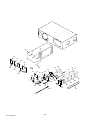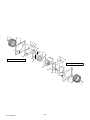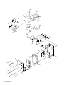
1
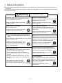
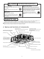
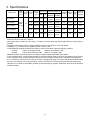
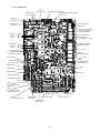
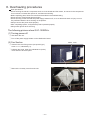
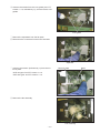
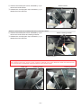
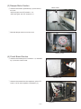
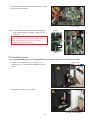
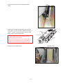
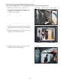
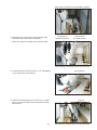
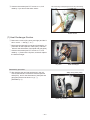
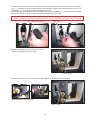
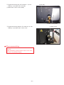
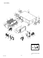
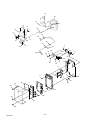
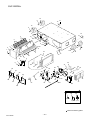
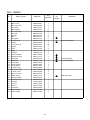
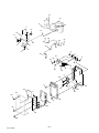
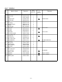
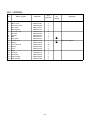
May 2013 FRESH MASTER HANDBOOK Model : GUF-50RD4 GUF-50RDH4 GUF-100RD4 GUF-100RDH4 GUF-100RDH4-60 Nameplate Repair work must be performed by the manufacturer, its service agent or a similarly qualified person in order to avoid hazards. No. U189 Contents 1. Safety precautions .................................................................... 3-4 2. Names and functions of components .......................................... 4 3. Specifications .............................................................................. 5 4. Outside dimensions ..................................................................... 6 5. Electrical wiring diagrams ......................................................... 7-8 6. Circuit board diagrams ........................................................... 9-10 7. Troubleshooting .....................................................................11-17 8. Overhauling procedures ........................................................ 18-28 9. Parts catalog ........................................................................ 29-63 GUF-50RD4 ................................................................... 30-35 GUF-50RDH4 ................................................................. 36-41 GUF-100RD4 ................................................................. 42-47 GUF-100RDH4 ............................................................... 48-55 GUF-100RDH4-60 .......................................................... 56-63 1. Safety precautions Read the following precautions thoroughly before the maintenance, and then inspect and repair the product in a safe manner. The types and levels of danger that may arise if the product is handled incorrectly are described with the warning symbols shown below. Warning Incorrect handling of the product may result in serious injury or death. Electric shock If you must inspect the circuitry while the power is on, do not touch the live parts. Turn off the power supply Be sure to shut off the power supply isolator before disassembling the unit for repair. (Failure to heed this warning may result in electric shock.) (Failure to heed this warning may result in electric shock.) Caution against electric shock Modification is prohibited Do not modify the unit. Be sure to follow this instruction. Use proper parts and tools For repair, be sure to use the parts listed in the service parts list of the applicable model and use the proper tools. (Failure to heed this warning may result in electric shock, fire and/or injury.) Prohibited Do not mix anything other than the specified coolant of the same type used in the outdoor unit. (Failure to heed this warning may result in electric shock, fire and/or injury.) Be sure to follow this instruction. Proper electric work Do not charge any coolant different from the coolant used in the outdoor unit. Use the electric wires designated for electric work, and conduct electric work in accordance with the "Electric Installation Engineering Standard", the "Indoor Wiring Regulations", and the Installation Instructions. (Failure to heed this warning may cause the pressure inside the freezing cycle to become abnormally high, leading to injury or other damage.) (Improper connection or wiring installation may result in electric shock and/or fire.) Replace damaged and/or degraded parts Toxic gas generation Be sure to replace the power-supply cord and lead wires if they are damaged and/or degraded. • Be careful that the coolant (R407C, R410A) does not leak in a flammable environment. • Conduct welding operation in an open room. • If the coolant gas leaks, open the windows while servicing. • Be sure to completely repair the leak. Close the service valve if the repair work is temporarily suspended. (If the coolant gas comes into contact with flames such as open fire, sparks and a heater, it may generate toxic gas.) Be sure to follow this instruction. Prohibited (Failure to heed this warning may result in electric shock and/or fire.) Be sure to follow this instruction. Check insulation Upon completing repair work, always measure the insulation resistance. Verify that it is at least 10 MΩ (with a 500 V DC insulation resistance tester), and then turn on the power. Be sure to follow this instruction. ─3─ (Inadequate insulation may result in electric shock.) Be sure to follow this instruction. Caution Incorrect handling of the product may result in injury or damage to properties including buildings and equipment. Caution for injury Prevent water leakage Do not work at a location where you do not have a sure footing. (Failure to heed this caution may result in a fall.) Prohibited Wear gloves • Before removing any of the water-related parts, completely drain the residual water from the piping. • Upon completing repair work, be sure to check the drainage of the indoor unit and that no water leaks from any of the piping connections. (Water leakage may cause buildings to soil, leading to secondary failure of other parts.) Wear gloves when servicing. (Failure to heed this caution may result in injury to your hands from sharp metal or other edges.) Be sure to follow this instruction. Be sure to follow this instruction. Request for repair Inspect the earth condition, and repair it if it is incomplete. Make sure that an earth leakage breaker or an overload protection device is installed. If it is not installed, recommend the dealer to install one. Make sure that the product operates properly upon completing repair work. Clean the product and the surrounding area, and then notify the customer of the completion of repair. 2. Names and functions of components Direct expansion coil Heats or cools the air supply after heat exchange. High efficiency filters (Optional parts) Removes dust from the outside air. Maintenance cover Permeable-film humidifier Performs clean humidifying of the air supply after heat exchange. Not available on GUF-50/100RD4 types Electronic expansion valve Maintenance cover (for humidifying) Control box Lossnay core Temperature and humidity are exchanged between supply air and exhaust air. Duct connection flange Damper plate Switches between the Lossnay ventilation and normal ventilation. Ceiling suspension fixture Discharge valve Service valve Drain discharge hole Exhaust fan Strainer (O-ring installed) Fan used to expel dirty air to outside of the room Water supply tube Supplies water to the permeable-film humidifier. Air filter Prevents clogs in the Lossnay core Air supply fan Fan to supply outside air to the inside *The illustration shows GUF-50RDH4. ─4─ 3. Specifications Model name External air load heat Power Power con- Air volume processing capability (kw) Humidifying Frequency Current supply sumption (Hz) (A) volume Cooling Heating (W) (V) m3/h L/S capability capability GUF-50RD4 GUF-50RDH4 GUF-100RD4 Singlephase 220-240 SingleGUF-100RDH4-60 phase 220 1.15 235-265 500 139 5.57 (1.94) 6.21 (2.04) - 33.5-34.5 54 P32 1.15 235-265 500 139 5.57 (1.94) 6.21 (2.04) 2.70 33.5-34.5 57 P32 2.20 480-505 1,000 278 11.44 (4.12) 12.56 (4.26) - 38-39 92 P63 2.20 480-505 1,000 278 11.44 (4.12) 12.56 (4.26) 5.40 38-39 98 P63 11.44 (4.12) 12.56 (4.26) 5.40 40.5 98 P63 50 GUF-100RDH4 60 Equivalent Noise Weight indoor unit (kg) (dB) capability 3.20 685 1,000 278 • The values given in the table for the noise level reflect the levels measured at a position 1.5 meters immediately below the unit in an anechoic chamber. • The noise at the air outlets (at a 45° angle, 1.5 meters in front) is about 5-6 dB (A) higher than the values given in the table. • The above values apply during Lossnay ventilation when the fan speed is set to high speed. * Capability in ( ) is heat recovery capability by the Lossnay cores. Cooling/Heating capability indicates the maximum value at operation under the following condition. Cooling: Indoor: 27°C DB/19°C WB Outdoor: 35°C DB/24°C WB Heating: Indoor: 20°C DB/13.8°C WB Outdoor: 7°C DB/6°C WB • Mitsubishi Electric measures products according to Japan Industrial Standard (JIS B 8628). • In the United Kingdom, on-site measurements by pitot tube method could be as much 20% different from JIS test room conditions. If the measuring point is close to sources of turbulence like bends, contractions and dampers, etc., it is difficult to measure the air volume correctly. A straight duct length more than 10D (D=duct diameter) from the source of turbulence is recommended for correct measurement. On-site measurement should therefore be carried out in accordance with BSRIA guideline (Commissioning Air Systems. Application procedures for buildings AG3/89.3 (2001)). ─5─ 4. Outside dimensions GUF-50RD4, GUF-50RDH4, GUF-100RD4, GUF-100RDH4, GUF-100RDH4-60 Location at which the duct direction can be changed N Ceiling suspension fixture (4×13×30 length hole for GUF-50 types) (4×15×30 length hole for GUF-100 types) Damper plate D Air exhaust fan EA (Exhaust air) RA (Return air) N Inspection opening T Maintenance cover Inspection Solenoid valve opening Heat exchange unit Humidifying element Maintenance space (N) 79 L M 100 Heat exchanger 60 Upper location at which the ceiling suspension fixture can be installed (for GUF-100 types) 30 Q øH Humidifying element* R Ceiling suspension fixture Maintenance cover P Gas pipe (Discharge hole) Liquid pipe Water intake strainer with check valve* (PT1/2 External thread) Air filters C 79 S (Water intake) A 79 Location at which the duct direction can be changed G Power cable installation port Control box High efficiency filter (Optional part) Lossnay core Solenoid valve unit with pressure regulator* 20 F SA (Supply air) øJ More than 600 OA (Outdoor air) Lossnay core Air filter High efficiency filter Fan Maintenance space E 150 to 250 K B Air supply fan Drain discharge hole (VP25 connection) (The components marked with * are available for GUF-50/100RDH4 types only) Model External dimension A B C Ceiling suspenDuct connection flange sion fixture pitch Nominal D E F diameter G H J GUF-50RD4 1288 1016 317 1185 1048 22 GUF-50RDH4 GUF-100RD4 1580 1231 398 1465 1271 16 GUF-100RDH4 GUF-100RDH4-60 Duct pitch K L M Humidification N P Q R S 99 Inspection opening Weight (kg) T 200 158.5 192 208 745 372.5 435 124 347 135 266 450 250 199 242 258 920 460 670 149 361 169 110 280 600 54 57 92 98 Unit (mm) ─6─ 5. Electrical wiring diagrams GUF-50RD4, GUF-100RD4 ─7─ GUF-50RDH4, GUF-100RDH4, GUF-100RDH4-60 A B GUF-50RDH4, GUF-100RDH4 220-240 V 50 GUF-100RDH4-60 220 V A ─8─ 60 B 6. Circuit board diagrams Circuit board diagrams and check points <FU-M05-D4> 1 GUF-50RD4, GUF-50RDH4, GUF-100RD4, GUF-100RDH4 Fuse $9 Power supply 220-240 V AC 50 Hz 7UDQVIRUPHUSULPDU\LQSXW 7UDQVIRUPHUVHFRQGDU\RXWSXW 16 to 23 V AC Supply fan &RPPRQ Exhaust fan &RPPRQ External humidifier control input Operation monitor output ZKHQVWRSSHG GXULQJRSHUDWLRQ Supply fan 220-240 V AC 50 Hz Exhaust fan 220-240 V AC 50 Hz KLJK Error monitor output QRUPDOO\ when there is an error low MA remote controller transmission cable KLJK low 14 V DC Solenoid value Full-wave rectified YROWDJH of 220-240 V AC 50 Hz (GUF-50/100RDH4W\SHV M-NET transmission cable 12 V DC OA thermistor M-NET transmission cable 6KLHOGHGSDUW Damper motor 220-240 V AC 50 Hz Water sensor GND Limit switch RA thermistor 5 V DC Gas pipe thermistor Liquid pipe thermistor LEV LED3 On when M-NET line power is on. LED2 On when MA remote controller power is on. Function switch 3 LED1 On when power is on. Address switch 7HQVGLJLW Branch No. switch Address switch 2QHVGLJLW ─9─ Function switch 1 Function switch 2 2 GUF-100RDH4-60 Fuse (6.3 A/250 V) Power supply 220 V AC 60 Hz Transformer primary (input) Transformer secondary (output) 16 to 23 V AC Supply fan (Common) Exhaust fan (Common) External humidifier control input Operation monitor output ZKHQVWRSSHG GXULQJRSHUDWLRQ Supply fan 220 V AC 60 Hz high Exhaust fan 220 V AC 60 Hz high Error monitor output QRUPDOO\ when there is an error) low MA remote controller transmission cable low 14 V DC Solenoid value Full-wave rectified voltage of 220 V AC 60 Hz M-NET transmission cable 12 V DC OA thermistor M-NET transmission cable (Shielded part) Damper motor 220 V AC 60 Hz Water sensor GND Limit switch RA thermistor 5 V DC Gas pipe thermistor Liquid pipe thermistor LEV LED3 On when M-NET line power is on. LED2 On when MA remote controller power is on. Function switch 3 LED1 On when power is on. Address switch (Tens digit) Branch No. switch Address switch (Ones digit) ─ 10 ─ Function switch 1 Function switch 2 7. Troubleshooting Work precautions • When servicing, be sure to recreate the malfunction two or three times before starting repairs. • When servicing, always keep proper footing. • When servicing, make sure that the power supply isolator is off, so as no electrical shock or injury to occur. Pay sufficient attention when working on the product. • Always connect the power wires properly. • When removing the circuit board, always hold it at both ends and remove carefully so as not to apply force to the surface mounted parts. • When removing the circuit board, be careful of the metal edges on the board. • When removing or inserting the connectors for the circuit board, hold the entire housing section. Never pull on the lead wires. • If it is thought that there is a printed circuit board malfunction, check for disconnected wires in the print pattern, burnt parts or discoloration. • If the printed circuit board is replaced, make sure that the switch settings on the new board are the same as the old board. • When servicing or checking around the humidifying unit, make sure to close the service valve. (1) Troubleshooting 1: The system will not start properly. Initialization checklist from installation to operation (Table 1) After checking the system, check the checkpoints listed below. Power supply (Table 1-1) No. Checkpoint Action 1 Is the main power supply on? 2 Do the main power supply switching capacity and wiring diameter meet specification? Turn on the main power supply. Use specified items. 3 Is the specified power supply of 220 to 240 V AC (220 V AC for GUF100RDH4-60) connected to the power supply terminal (TM1)? Connect the specified power supply. 4 Has the fuse (FUSE 1) on the circuit board blown? Replace the circuit board. 5 Are connector CNT of the transformer primary (input) and connector CN3T of Connect them securely. the transformer secondary (output) on the circuit board securely connected? 6 Is the power supply wiring incorrectly wired, or is there a faulty connection? Make secure connections. 7 Is power display LED1 (red) on the circuit board unlit? Check the above checkpoints. Transmission cables (Table 1-2) Check the following checkpoints when connecting with the remote controller or M-NET controller. No. Checkpoint Action 1 Do the transmission cables meet regulations? (Type, diameter) Use specified cables. 2 Is the transmission cable wired at least 5 cm away from the power supply Wire the transmission cable at least 5 cable? cm away from the power supply cable. 3 Are multiple transmission or signal cables wired to the same power cable Wire the transmission cables away duct? from the signal cables. 4 Are multiple transmission cables wired with multi-core cables? Use suitable cables to wire the transmission cables so that they are separated from one another. 5 Are the transmission cables securely connected to the terminals? 6 Are the address switches on the circuit board (SW11 and SW12) set to the correct number? Connect them securely. Make the setting so that the address does not duplicate that of other devices within M-NET control. Connect them to the specified terminal blocks. 7 Are the transmission cables connected to the specified terminal blocks? MA remote controller: TM2 1, 2 M-NET controller: TM2 A , B ─ 11 ─ Signal cables to external devices (Table 1-3) Check the following checkpoints when outputting the operation monitor and malfunction monitor. No. Checkpoint Action 1 Do the signal cables meet regulations? (Type, diameter) Use specified cables. 2 Is the signal cable wired at least 5 cm away from the power supply cable? Wire the signal cable at least 5 cm away from the power supply cable. 3 Are multiple transmission or signal cables wired to the same power cable Wire the transmission cables away duct? from the signal cables. 4 Are multiple signal cables wired with multi-core cables? Use suitable cables to wire the signal cables so that they are separated from one another. 5 Are the signal cables securely connected to the terminals? 6 Are the signal cables connected to the specified terminal blocks? Operation monitor: TM3 9, 0 Malfunction monitor: TM3 7, 8 7 Are the output capacities of the operation monitor and malfunction monitor within the ratings? Connect them securely. Connect them to the specified terminal blocks. Output Operation monitor Maximum rating 240 V AC, 1 A 24 V DC, 1 A Malfunction monitor 240 V AC, 1 A 24 V DC, 1 A Use them within the ratings. Minimum rating 220 V AC, 100 mA 5 V DC, 100 mA 220 V AC, 100 mA 5 V DC, 100 mA (Table 2) State of machine Remote controller Does not operate. • Remote controller display does not appear. • The power display “ ” does not appear on the remote controller. (When PAR-21MAA is used) The power display “ ” does not appear on the remote controller when power is supplied to the system. (When PAR-F27MEA is used) Cause Power is not supplied to Fresh Master, or power that does not follow specifications is used. Is there a connection of 3 or more remote controllers, or 16 or more Fresh Master units? The remote controller is connected to TM2 A , B (terminal block for M-NET transmission cable). The power of the outdoor unit is not turned on. Power is not supplied to the transmission cable that connects indoor units and an outdoor unit. Faulty connection of the M-NET transmission cable The number of Fresh Masters, indoor units, or remote controllers connected to the transmission cable exceeds the power supply capacity of the outdoor unit. ─ 12 ─ Remedy Check the power supply to Fresh Master. (Refer to Table 1-1) Check the number of units connected. Connect the transmission cable to TM2 1, 2. ME remote controller is powered by the outdoor unit. Turn on the power of the outdoor unit. Check the settings of the outdoor unit. See the City Multi databook for details. See Table 1-2. Connect Fresh Masters, indoor units, or remote controllers within the power supply capacity of the outdoor unit. See the City Multi databook for details. State of machine Remote controller Does not operate. The power display “ ” does not appear on the remote controller when power is supplied to the system. (When PAR-F27MEA is used) Cause When a power supply unit is used: 1The power supply unit is not connected with the transmission cable. 2The power supply unit is not turned on. 3The length of the M-NET transmission cable wiring from the power supply unit is longer than specified (longer than 200 m). The transmission cable power supply restrictions have been exceeded. Remedy 1Connect the power supply unit with the transmission cable. 2Check the power of the power supply unit. 3Check the length of the transmission cable wiring. (See the technical manual for details about the regulations.) Make connections within the transmission cable power supply restrictions of the outdoor units, or the power supply units. (See the technical manual for details about the restrictions.) Cool air or warm The LCD screen The restart protection delay circuit is Wait for a while. air does not come shows that it is in in operation for 3 minutes. (To protect the compressor, a 3 out. operation. minutes delay circuit is built into the OA processing unit. Therefore, sometimes the compressor will not start operating immediately. This delay may be up to 3 minutes.) It runs briefly, but soon stops. Does not humidify. (GUF-50/100RDH4 types only) Dry mode cannot be set from the remote controller. Dry mode can be set from the central controller, but does not operate. OA processing unit operation has restarted following the heating and defrosting operation. The CHECK and The air inlet or outlet of the OA procheck code flash- cessing unit and/or outdoor unit is obstructed. es on the LCD screen. The filters are clogged with dust and dirt. The OA processing unit is not set to the “ heating” mode. — Water is not supplied. There is no dry mode on the OA processing unit. Cannot set to dry mode — from the remote controller. Dry mode display When the unit is set to dry mode from is flashing in LCD. the central controller, the dry mode display flashes on the LCD and the OA processing unit fan operates. ─ 13 ─ Wait for a while. (Heating operation starts after defrosting operation has ended.) Restart after removing the obstruction. Restart after cleaning the filters. Set to the heating mode. Open the service valve. Use a mode other than dry mode. (2) Troubleshooting 2: An error code is displayed on the remote controller. See below for possible remedies when there is an error during test operation and CHECK followed by a 4-digit number is displayed on the remote controller. Note: The components marked with * are available for GUF-50/100RDH4 types only. Error code Error content 0900 Test run 2600 Drain error Cause Remedy Is the test operation switch of either the Set the test operation switch (SW1-1, 7, fan, bypass damper, or humidifier sole- 8*) to OFF. noid valve* turned ON? Drain water is not properly discharged. The body must be levelly installed. The drain pipe must be installed with a gradient of more than 1/100. Is there a leak from the permeable-film • Fix the water leak. humidifier*? • Replace the humidifier element*. When no problem is found after check- Replace the circuit board. ing the above items. 2601 Disconnected water sensor connector Is the CN4D connector firmly connected? Firmly connect the connector. Is the relay connector between the Firmly connect the connector. circuit board and water sensor firmly connected? When no problem is found after check- Replace the circuit board. ing the above item. 3602 Damper motor error Is the CNL connector firmly connected? Firmly connect the connector. Is the connector of the damper motor Firmly connect the connector. section firmly connected? Does the damper operate when the damper motor is running? Replace the damper motor if it is not working. When no problem is found after check- Replace the circuit board. ing the above items. 4116 Fan motor error 5101 Indoor temperature • Are the connectors of each thermistor • Firmly connect each connector. sensor error firmly connected? • Firmly connect each connector. Liquid pipe temper- • Is each relay connector firmly connected? ature sensor error • Replace the circuit board. Gas pipe tempera- • When no problem is found after checking the above item. ture sensor error 5102 5103 The motor continues to run when the operation is stopped. 5104 Outdoor temperature sensor error 6600 Indoor unit address There are duplicate address settings, setting error meaning there are indoor units with the same address. Communication Any of the transmission cables of the error (Transmission indoor units, Fresh Master, or outdoor units was wired, or the polarity was processor H/W changed with the power ON. error) 6602 Specified power supply is not used. Earth fault in the transmission cable Replace the circuit board. Check the addresses of devices in the system. Simultaneously turn OFF the power of the indoor units, Fresh Master, and the outdoor units, and then, turn them ON again. Check the power supply. Check the transmission cable wiring and shielding. The setting of the outdoor unit is incorrect. See the service manual of the outdoor unit. Transmission data was changed due to Inspect the transmission waveform and noise in the transmission cable line. noise in the transmission cable line. Malfunction of a controller for the device If the controller is normal, it is a malfuncin which the error occurs. tion of the circuit board. ─ 14 ─ Error code Error content 6603 Communication error (Bus busy error in the transmission line) 6606 6607 Cause The transmission processor cannot transmit data because short-period voltages such as noise continuously occurs in the transmission cable line. Malfunction of a controller for the device in which the error occurs. Communication error (Handshake error) Remedy Inspect the transmission waveform and noise in the transmission cable line. If the controller is normal, it is a malfunction of the circuit board in Fresh Master. Replace the circuit board. Simultaneously turn OFF the power of the indoor units, Fresh Master, and the outdoor units, and then, turn them ON again. Data was not transmitted correctly due to an accidental misoperation of the controller for the device in which the error occurs. Malfunction of a controller for the device If the same error occurs again, it is a malin which the error occurs. function of the circuit board in the device in which the error occurs. Communication er- (Only when the error occurs in Fresh ror (No ACK error) Master.) Single coolant system 1The address has been changed in midstream. 2Improper wiring or disconnection of the transmission cable 3Malfunction of the controller 4Malfunction of the remote controller (When the switch (SW3-1) is ON) Group operation system with multiple coolant lines 1The above causes 1 to 4 (When Fresh Master is interlocked with the indoor units in the different coolant line) 2Short circuit or disconnection of the transmission cable to the terminal block for central control (TB7) in the outdoor unit 3The outdoor unit in one of the coolant lines is shut down. 4The setting of the outdoor unit is incorrect. Simultaneously turn OFF the power of the outdoor units and Fresh Master, and then, turn them ON again. In the case of the accidental malfunction, the unit returns to normal. If the unit does not return to normal, check the causes 1 to 4. Simultaneously turn OFF the power of the outdoor units and Fresh Master, and then, turn them ON again. In the case of the accidental malfunction, the system returns to normal. If the system does not return to normal, check the causes 1 to 4. If none of the above causes applies, check the error display LEDs of the other remote controllers or outdoor units. • When there is an error See the error code, and repair troubled sections according to the instructions described in the troubleshooting. • When there is no error It is a malfunction of the circuit board in Fresh Master. If the error occurs after the unit operates normally, the following can be caused. See the service manual of the outdoor unit. • Total capacity error (7100) • Capacity code setting error (7101) • The number of connected devices error (7102) • Address setting error (7105) ─ 15 ─ Error code Error content Cause 6607 Communication er- System connected with MELANS ror (No ACK error) a) Malfunction only in some of the units • Refer to the causes for the single coolant system b) Malfunction in all the indoor units and Fresh Master units in one coolant line 1Causes of total capacity error (7100) 2Causes of capacity code setting error (7101) 3Causes of the number of connected devices error (7102) 4Causes of Address setting error (7105) 5Short circuit or disconnection of the transmission cable to the terminal block for central control (TB7) in the outdoor unit 6The outdoor unit is shut down. 7Fault in the electrical system of the outdoor unit c) Malfunction in all the indoor units and Fresh Master units 1The above causes 1 to 7 2The setting of the outdoor unit is incorrect. 3Wiring from the power supply unit to the transmission cables is disconnected, or the power supply unit is shut down. 4Malfunction of the system controller (MELANS) 6608 Communication 1The transmission cables were wired error (No answer or the polarity was changed with the error) power ON. 2A transmission error repeatedly occurs due to noise or the like. 3The voltage/signal in the transmission cable drops because the length of the transmission cable wiring is longer than specified. • Maximum extension: 500 m or less, Power supply line must be 200 m or less • ME remote controller wiring: 10 m or less 4The voltage/signal in the transmission cable drops because the transmission cable does not meet specification. • Cable diameter: 1.25 to 2.0 mm2 ─ 16 ─ Remedy Refer to the remedy for the single coolant system Check the error display LEDs of the outdoor unit. • When there is an error See the error code, and follow the instructions described in the troubleshooting. • When there is no error Check the causes 5 to 7 written in the left. See the service manual of the outdoor unit. Check the voltage of the transmission cables for central control. • When the voltage is 20 V DC or more Check the causes 1 and 2 written in the left. • When the voltage is less than 20 V DC Check the cause 3 written in the left. See the service manual of the outdoor unit. Simultaneously turn OFF the power of the indoor units, Fresh Master, and the outdoor units, and then, turn them ON again. • When the system returns to normal It means the error was detected because the transmission cables were wired with the power ON. • If the system does not return to normal Check the causes 3 and 4 written in the left, and repair the troubled sections. If none of the above causes applies, inspect the transmission waveform and noise in the transmission cable line. (If the error 6602 occurs, noise will probably be a cause.) Error code Error content 6831 MA remote control6832 ler communication 6833 error 6834 7101 7106 Remedy Check the transmission cable for disconnection or looseness. The voltage/signal in the MA remote controller transmission cable drops. Check the transmission cable if the length is beyond the range of the wiring regulation A signal was changed due to noise in the MA remote controller transmission cable. Failure in the transmit/receive circuit for the MA remote control of the MA remote controller or Fresh Master Capacity code set- Capacity code setting of Fresh Master ting error is wrong. Remote controller setting error Booting system HO Unable to register - - Cause Contact failure of the MA remote controller transmission cable Operation display comes up with the Remote controller, however it turns off immediately. The MA Remote controller was connected with the switch (SW3-1) OFF. Inspect noise in the transmission signal. If no problem is found after checking the above items, it is a malfunction of the MA remote controller or Fresh Master. Check the capacity code setting switches (SW2-1 to SW2-6). When the MA remote controller is directly connected to Fresh Master, switch (SW31) must be ON. Have 10 minutes passed since system After system boot-up, HO may flash for a boot-up? maximum of 10 minutes. However, this is not a malfunction. Has group registration been made? Conduct group registration. If there is a master system controller such as the central controller, use the controller to conduct group registration. Has the Fresh Master address been If the Fresh Master main unit address has changed? been changed, conduct the group registration again. When no problem is found after check- If HO continues to flash for more than 10 ing the above items. minutes after reregistering the group and rebooting, replace the circuit board. Change the setting of the switch (SW3-1) Fresh Master which is linked with indoor units, cannot be group registered and reset the registration or register it as other than the interlock setting with the interlocked. Remote controller. Main power is not supplied to Fresh Supply Main Power. Master. ─ 17 ─ 8. Overhauling procedures Work precautions • When touching the electric components such as circuit boards and fan motors, do not touch the components for more than 5 minutes after power-off, and then start working. • Before replacing parts, follow the instructions described in the troubleshooting. • When servicing, always keep proper footing. • When servicing, make sure that the power supply isolator is off, so as no electrical shock or injury to occur. Pay sufficient attention when working on the product. • Always connect the power wires properly. • After completing repairs, verify that the product operates properly. • Always wear gloves when servicing. The following pictures show GUF-100RDH4. (1) Turning power off 1 Shut down the unit. 2 Turn off the power supply isolator on the distribution board. (2) Fan Section Maint. cover 1 Unscrew the cover fixing screw (one special (spl.) screw 4 × 11, indicated by ). 2 Pull back the hinge. Open the maintenance (maint.) cover and lift it off the fix piece. Hinge 3 Remove the Lossnay cores from the unit. Lossnay core ─ 18 ─ Filter 4 Unscrew the screws from the core guides (two PTT screws 4 × 12, indicated by ), and remove the core guides. Core guide 5 Remove the separators from the fan parts. 6 Disconnect the connectors for the motor lead wire. Separator 7 Unscrew the screws* (indicated by ) from the motor fix plate. Motor fix plate *GUF-50 types: four PTT screws 5 × 10 GUF-100 types: six PTT screws 5 × 10 8 Remove the fan assembly. Fan assembly ─ 19 ─ Motor 9 Unscrew the screws (two screws, indicated by ) to remove the reinforcement. Reinforcement 0 Unfasten the cord clips (two clips, indicated by ) to release the motor lead wire. When the motor lead wire is sealed as shown in the picture below 9 Unscrew the screws (two screws, indicated by ) to remove the reinforcement and sealing materials. Peel the sealing material. 0 Unfasten the cord clips (two clips, indicated by ) to release the motor lead wire. Reinforcement Assembly precaution After replacing the motor, set the center of packing material of the motor lead wire under the reinforcement. It is not required to reinstall the metal part shown in the picture below. Metal part Sealing material <Before replacing the motor> Packing material <After replacing the motor> ─ 20 ─ (3) Damper Motor Section 1 Unscrew the screws* (indicated by ) from the motor cover. Motor cover *GUF-50 types: two PTT screws 4 × 6 GUF-100 types: two PTT screws 4 × 8 2 Take the damper motor out of the cover. Damper motor (4) Circuit Board Section 1 Unscrew the screws (four PT screws 4 × 8, indicated by ) from the control cover. Control cover 2 Unscrew the screws from the capacitors. (One PTT screw 4 × 8 for each capacitor, indicated by ) ─ 21 ─ Capacitor 3 Remove all lead wires connected to the circuit board. 4 Take the circuit board out. Circuit board Note: The compatible circuit board, which is equipped with switches (SW4 and SW5), is used as a service part. Assembly precaution After replacing the circuit board, switches (SW4 and SW5, indicated by ) must be set to "HIGH". Otherwise, the unit will not work. "HIGH" SW4 SW5 "HIGH" (5) Humidifier Section Note: GUF-50/100RD4 types are not equipped with the humidifier elements, hose bands, and tubes. 1 Unscrew the screws (seven PTT screws 5 × 10, indicated by ) to remove the humidifier (H. elem.) cover. H. elem. cover 2 Remove the H. elem. cover (inside). ─ 22 ─ H. elem. cover (inside) 3 Remove the tubes from the humidifier elements (elem). Tube 4 Holding the hose bands indicated by [1] to [6] with your fingers, remove the tubes. Referring to the procedure 5 below, remove the tube at the rear while taking out the front humidifier elem. Precautions • To remove the tubes, hold and slide the hose bands and remove the tubes. • Do not remove the tube from the solenoid valve. • When removing the tubes, be sure that water is collected on the drain pan inside the main unit. [6] Tube [5] Solenoid valve [4] [3] [2] Humidifier elem Tube [1] Hose band 5 Remove the humidifier elems. Humidifier elem ─ 23 ─ (6) Solenoid Valve and Water Sensor Section Note: GUF-50/100RD4 types are not equipped with the solenoid valve and cover (SOLV). 1 Remove the H. elem. covers. → See (5) 1 to 2. Cover (left) Cover (center) Cover (right) 2 Unscrew the screws (eleven PTT screws 5 × 10, indicated by ) to remove the cover (left), cover (center), and cover (right). 3 Disconnect the connectors for the thermistor lead wires and expansion valve lead wire. (Indicated by ) 4 Unscrew the screws (two PTT screws 4 × 8, indicated by ) to remove the fix piece. Fix piece 5 Unscrew the screws (two PTT screws 4 × 8, indicated by ) to remove the fix plate. ─ 24 ─ Fix plate Humidifier elem Water sensor and solenoid valve installation positions 6 Disconnect the connectors for the solenoid valve lead wires and water sensor lead wires. Connector for the solenoid valve Connector for the water sensor 7 Remove the pipe connected to the solenoid valve. *The heat exchanger is exceptionally removed for easy understanding. 8 Loosen the screw (one PTT screw 4 × 8, indicated by ) to remove the cover (SOLV). Cover (SOLV) *The heat exchanger is exceptionally removed for easy understanding. 9 Unscrew the screws (two PTT screws 4 × 8, indicated by ) to remove the cover B and solenoid valve from the unit. ─ 25 ─ Cover B *The heat exchanger is exceptionally removed for easy understanding. 0 Unscrew the screws (two PTT screws 4 × 8, indicated by ) to remove the water sensor. *The heat exchanger is exceptionally removed for easy understanding. Water sensor (7) Heat Exchanger Section 1 Remove the covers (left, center, and right) and the H. elem. covers. → See (6) 1 to 2. 2 Disconnect the lead wire connectors (indicated by ). (Lead wire for the expansion valve (LEV), and lead wires for the thermistors of the liquid and gas pipes) 3 Unscrew the screws (two PTT screws 4 × 8, indicated by ). Remove the fix piece, and then replace the heat exchanger. fix piece Heat exchanger Reassembly procedure 4 After inserting the new heat exchanger in the unit, connect the lead wire connectors for the expansion valve (LEV), and for the thermistors of the liquid and gas pipes (removed as shown in (7) 2). Water stop (steel plate) (Indicated by ) Water stop (resin) ─ 26 ─ 5 Hold the water stop (resin) with your fingers, and hold the lead wires by the fix piece (removed as shown in (7) 3). Hook the fix piece on the slit of the heat exchanger. Tighten the screws (two PTT screws 4 x 8, indicated by ), and secure the heat exchanger to the unit. Set the lead wires u-shaped as shown in the following picture (indicated by ), and secure the lead wires with the cord bands so as not to move the lead wires toward the cover side. Assembly precaution If the lead wires are not secured, condensed water may run down the read wires, and result in water leak. Slit of the heat exchanger Cord band 6 Tighten the screws (two PTT screws 5 × 10, indicated by ) to attach the cover (right). Cover (right) 7 Tighten the screws (five PTT screws 5 × 10, indicated by ) to attach the cover (center). Tighten tentatively this screw first. Cover (center) ─ 27 ─ 8 Tighten the screws (four PTT screws 5 × 10, indicated by ) to attach the cover (left). Cover (left) 9 Attach the H. elem. cover (inside). H. elem. cover (inside) 0 Tighten the screws (Seven PTT screws 5 x 10, indicated by ) to attach the H. elem. cover. When reassembling Reassemble the unit in the reverse order of disassembly. After reassembly, always make a test run to be sure that the unit operates properly. ─ 28 ─ H. elem. cover 9. Parts catalog Please note the following when using the parts catalog. 1. When ordering parts, always indicate the part number, part name, and the number of parts required. 2. Parts are not always available, and it may take time for you to receive them. 3. There may be specification improvements. 4. Parts marked are critical for safety. To maintain safety and performance, always replace these parts with the parts prescribed. Description of screw abbreviations Screw 4 × Screw diameter 16 Length Abbreviation Description PC screw Cross recess flat head machine screw PRC screw Cross recess oval head machine screw PP screw Cross recess pan head machine screw SW · PP screw Cross recess pan head screw with spring washer PPT screw Cross recess tapping screw PCT screw Cross recess flat head tapping screw PTT screw Cross recess truss head tapping screw PT screw Cross recess truss head machine screw SET screw Slotted head stop screw SQ · SET screw Square head stop screw P · SET screw Pan head stop screw PMT screw Primer truss head screw HS · SET screw Hexagon head stop screw P · R · W screw Cross recess round wood screw P · C · W screw Cross recess flat head wood screw P · R · C · W screw Cross recess round and flat wood screw R · W screw Slotted round wood screw PW · PP screw Cross recess pan head screw with small washer SW-PW · PP screw Cross recess pan head machine screw with spring washer and flat washer ─ 29 ─ GUF-50RD4 12 6 14 13 12 6 6 13 5 14 14 15 11 5 10 1 2 3 13 4 16 6 17 9 12 6 12 18 5 13 3 9 6 7 9 6 5 19 29 20 8 6 14 28 21 22 28 23 24 25 30 27 34 33 31 26 31 26 32 26 6 35 36 2 pcs. 2 pcs. 16 pcs. shows accessory parts. ─ 30 ─ GUF-50RD4 GUF-50RD4 No. 1 2 3 4 5 6 7 8 9 10 11 12 13 14 15 16 17 18 19 20 21 22 23 24 25 26 27 28 29 30 31 32 33 34 35 36 Name of part Spl screw 4×11 Maint. cover PTT screw 4×12 Core guide Filter stopper PTT screw 4×8 Fix piece Fix plate Filter Core guide Lossnay core Flange PT screw 6×12 Hanger Cover Hinge Fix piece Heat exchanger Expansion valve Thermistor Thermistor Cover (left) Cover (center) Cover (right) H. elem. cover PTT screw 5×10 H. elem. cover Spl screw 4×12 Water sensor Special washer PTT screw 4×8 Fix plate Cover B Cover A Heat insulator Heat insulator Parts No. Q'ty pcs/unit M34 074 017 R50 542 486 H00 000 488 R50 216 381 R50 521 710 H00 000 487 R50 429 700 R50 429 699 R50 521 717 R50 478 382 R50 542 711 R50 028 610 H00 000 244 R50 095 380 R50 542 706 R50 466 344 Y50 029 712 R50 472 699 R50 474 737 R40 632 936 R40 647 340 R50 530 691 R50 530 692 R50 530 694 R50 429 698 H00 189 007 R50 429 486 M35 282 045 Y55 011 218 K81 602 035 H00 260 045 Y55 011 698 Y55 011 696 Y55 011 692 R50 530 699 R50 530 700 1 1 2 1 8 45 1 1 4 1 2 4 15 4 2 1 1 1 1 1 1 1 1 1 1 31 1 2 1 1 8 1 1 1 2 2 ─31─ Critical for safety Remarks With filter stoppers For coolant For the gas pipe For the liquid pipe With lead wires 51 52 53 54 55 26 26 56 Air supply fan assembly 57 Air exhaust fan assembly 55 26 26 57 58 26 54 52 53 ─ 32 ─ GUF-50RD4 51 GUF-50RD4 No. 51 52 53 54 55 56 57 58 Name of part Special nut (8) Tab washer Centrifugal fan Fan base Spl washer (10) Motor Motor fix plate Motor Parts No. Q'ty pcs/unit R50 331 067 M34 398 077 R50 351 480 R50 478 707 M34 706 465 Y55 011 453 R50 351 713 Y55 011 454 2 2 2 2 2 1 2 1 ─33─ Critical for safety Remarks Left-handed φ220 79 80 78 73 81 74 76 72 71 83 82 77 6 OA 76 84 83 75 6 85 6 RA 83 86 87 88 6 93 92 91 89 6 90 6 6 101 6 102 6 94 95 86 6 89 99 97 89 98 96 89 ─ 34 ─ GUF-50RD4 6 100 87 GUF-50RD4 No. 71 72 73 74 75 76 77 78 79 80 81 82 83 84 85 86 87 88 89 90 91 92 93 94 95 96 97 98 99 100 101 102 Name of part Fix piece Motor cover PTT screw 4×6 Bush Damper motor Special bush Rod Pull spring Damper support Damper Special bush Thermistor Cord clip Cord clip Thermistor PT screw 4×8 BS Lock washer (4) Transformer PT screw 4×8 PPT screw 4×20 Terminal block Cord band TB fix plate Control cover Wiring diagram Side plate Bush PPT screw 3×8 Circuit board PCB fix plate Capacitor PCB fix plate Parts No. Q'ty pcs/unit R50 533 693 Y50 151 706 H00 312 007 Y50 115 225 Y50 061 260 R50 054 225 R50 232 150 R50 069 156 R50 472 716 R50 472 715 M31 234 089 Y55 011 215 R50 399 223 R50 399 224 Y55 011 216 H00 011 008 H00 013 076 Y55 001 217 H00 000 349 H00 141 005 Y55 011 217 K83 170 228 Y55 011 693 R50 429 693 Y55 011 368 Y55 011 695 K82 163 225 H00 003 005 Y55 007 171 R50 327 730 Y55 011 287 Y55 011 694 1 1 30 1 1 2 1 1 1 1 2 1 3 4 1 2 2 1 5 1 1 1 1 1 1 1 3 1 1 1 2 1 ─35─ Critical for safety Remarks AC220・240V -50 to 105゚C -50 to 105゚C 3P・With lead wires White FU-M05-D1 4.0μF・440VAC GUF-50RDH4 12 6 14 13 12 6 6 13 5 14 14 15 11 5 16 6 2 3 4 17 10 12 9 6 1 9 3 12 18 5 13 5 9 8 6 14 19 6 7 6 42 41 20 39 21 30 22 23 29 24 45 38 29 44 31 35 32 28 26 27 32 33 43 40 25 26 13 43 32 36 34 43 47 47 37 46 26 6 48 49 16 pcs. 2 pcs. 2 pcs. shows accessory parts. ─ 36 ─ GUF-50RDH4 GUF-50RDH4 No. 1 2 3 4 5 6 7 8 9 10 11 12 13 14 15 16 17 18 19 20 21 22 23 24 25 26 27 28 29 30 31 32 33 34 35 36 37 38 39 40 41 42 43 44 45 46 47 48 49 Name of part Spl screw 4×11 Maint. cover Spl screw 4×12 Core guide Filter stopper PTT screw 4×8 Fix piece Fix plate Filter Core guide Lossnay core Flange PT screw 6×12 Hanger Cover Hinge Fix piece Heat exchanger Expansion valve Thermistor Thermistor Cover (left) Cover (center) Cover (right) H. elem. cover PTT screw 5×10 Strainer Pipe Spl screw 4×12 Water sensor Special washer PTT screw 4×8 Fix plate Cover B Solenoid valve Cord band Drain tube Cord bush Cover A Cover (SOLV) Hose band Tube Hose band Tube Tube H. elem. cover Humidifier elem Heat insulator Heat insulator Parts No. Q'ty pcs/unit M34 074 017 R50 542 486 H00 000 488 R50 216 381 R50 521 710 H00 000 487 R50 429 700 R50 429 699 R50 521 717 R50 478 382 R50 542 711 R50 028 610 H00 000 244 R50 095 380 R50 542 706 R50 466 344 Y50 029 712 R50 472 699 R50 474 737 R40 632 936 R40 647 340 R50 530 691 R50 530 692 R50 530 694 R50 429 698 H00 189 007 R50 395 319 R50 429 303 M35 282 045 Y55 011 214 K81 602 035 H00 260 045 Y55 011 698 Y55 011 696 Y55 011 213 D40 007 344 R50 530 388 M45 649 226 Y55 011 692 Y55 011 697 R50 117 223 R50 429 390 R50 261 223 R50 428 390 R50 429 389 R50 429 486 R50 261 714 R50 530 699 R50 530 700 1 1 2 1 8 46 1 1 4 1 2 4 15 4 2 1 1 1 1 1 1 1 1 1 1 31 1 1 4 1 1 10 1 1 1 1 1 1 1 1 1 1 4 1 1 1 2 2 2 ─37─ Critical for safety Remarks With filter stoppers For coolant For the gas pipe For the liquid pipe With lead wires 200V・With a drain valve D12.5 D12.5 With packing 61 62 63 64 65 26 26 26 66 Air supply fan assembly 67 Air exhaust fan assembly 65 26 26 67 68 26 64 62 63 ─ 38 ─ GUF-50RDH4 61 GUF-50RDH4 No. 61 62 63 64 65 66 67 68 Name of part Special nut (8) Tab washer Centrifugal fan Fan base Spl washer (10) Motor Motor fix plate Motor Parts No. Q'ty pcs/unit R50 331 067 M34 398 077 R50 351 480 R50 478 707 M34 706 465 Y55 011 453 R50 351 713 Y55 011 454 2 2 2 2 2 1 2 1 ─39─ Critical for safety Remarks Left-handed φ220 89 90 88 83 91 84 86 82 81 93 92 87 6 86 OA 94 93 85 6 95 6 RA 93 96 97 98 6 103 102 101 99 6 6 100 112 6 6 111 6 113 6 104 105 96 6 99 110 6 6 109 108 99 107 106 99 ─ 40 ─ GUF-50RDH4 97 GUF-50RDH4 No. 81 82 83 84 85 86 87 88 89 90 91 92 93 94 95 96 97 98 99 100 101 102 103 104 105 106 107 108 109 110 111 112 113 Name of part Fix piece Motor cover PTT screw 4×6 Bush Damper motor Special bush Rod Pull spring Damper support Damper Special bush Thermistor Cord clip Cord clip Thermistor PT screw 4×8 BS Lock washer (4) Transformer PT screw 4×8 PPT screw 4×20 Terminal block Cord band TB fix plate Control cover Wiring diagram Side plate Bush PPT screw 3×8 Circuit board PCB fix plate Capacitor Cement resistor PCB fix plate Parts No. Q'ty pcs/unit R50 533 693 Y50 151 706 H00 312 007 Y50 115 225 Y50 061 260 R50 054 225 R50 232 150 R50 069 156 R50 472 716 R50 472 715 M31 234 089 Y55 011 215 R50 399 223 R50 399 224 Y55 011 216 H00 011 008 H00 013 076 Y55 001 217 H00 000 349 H00 141 005 Y55 011 217 K83 170 228 Y55 011 693 R50 429 693 Y55 011 367 Y55 011 695 K82 163 225 H00 003 005 Y55 007 171 R50 327 730 Y55 011 287 Y55 003 215 Y55 011 694 1 1 30 1 1 2 1 1 1 1 2 1 3 4 1 2 2 1 7 1 1 1 1 1 1 1 3 1 1 1 2 1 1 ─41─ Critical for safety Remarks AC220・240V -50 to 105゚C -50 to 105゚C 3P・With lead wires White FU-M05-D1 4.0μF・440VAC GUF-100RD4 12 6 14 13 12 6 17 6 6 13 5 14 14 15 11 5 10 1 2 3 13 4 16 6 17 9 12 6 12 18 5 13 3 9 6 7 9 6 5 19 29 20 8 6 14 28 21 22 28 23 24 25 30 27 34 33 31 26 31 26 32 26 6 35 16 pcs. 4 pcs. 36 2 pcs. 37 2 pcs. shows accessory parts. ─ 42 ─ GUF-100RD4 GUF-100RD4 No. 1 2 3 4 5 6 7 8 9 10 11 12 13 14 15 16 17 18 19 20 21 22 23 24 25 26 27 28 29 30 31 32 33 34 35 36 37 Name of part Spl screw 4×11 Maint. cover Spl screw 4×12 Core guide Filter stopper PTT screw 4×8 Fix piece Fix plate Filter Core guide Lossnay core Flange PT screw 6×12 Hanger Cover Hinge Fix piece Heat exchanger Expansion valve Thermistor Thermistor Cover (left) Cover (center) Cover (right) H. elem. cover PTT screw 5×10 H. elem. cover Spl screw 4×12 Water sensor Special washer PTT screw 4×8 Fix plate Cover B Cover A Cord band Heat insulator Heat insulator Parts No. Q'ty pcs/unit M34 074 017 R50 543 487 H00 000 488 R50 219 381 R50 522 710 H00 000 487 R50 429 700 R50 430 695 R50 522 717 R50 481 381 R50 544 710 R50 430 609 H00 000 244 R50 054 383 R50 543 704 R50 466 344 Y50 029 712 R50 473 699 R50 474 737 R40 632 936 R40 647 340 R50 531 693 R50 531 696 R50 531 697 R50 430 694 H00 189 007 R50 430 486 M35 282 045 Y55 011 218 K81 602 035 H00 260 045 Y55 012 692 Y55 011 696 Y55 011 692 R50 530 228 R50 530 699 R50 530 700 1 1 2 1 8 81 1 1 4 1 2 4 16 4 2 1 2 1 1 1 1 1 1 1 1 34 1 2 1 1 8 1 1 1 4 2 2 ─43─ Critical for safety Remarks With filter stoppers For the gas pipe For the liquid pipe With lead wires 51 53 52 54 56 57 55 58 59 26 6 60 61 62 63 26 59 61 Air exhaust fan assembly 58 57 56 26 55 Air supply fan assembly 64 26 60 26 6 54 53 ─ 44 ─ GUF-100RD4 52 51 GUF-100RD4 No. 51 52 53 54 55 56 57 58 59 60 61 62 63 64 Name of part Spl nut (12) Washer (12) Centrifugal fan Fan base Inlet ring PT screw 6×20 Spl washer (6) Spacer Bush Motor fix plate Key Motor Nut (6) Motor Parts No. Q'ty pcs/unit R50 218 067 K83 466 113 R50 479 480 R50 480 707 R50 264 711 H00 157 008 M34 043 080 R50 000 095 R50 217 225 R50 218 712 Y50 033 104 Y55 012 454 H00 061 050 Y55 012 453 2 2 2 2 2 8 8 8 8 2 2 1 8 1 ─45─ Critical for safety Remarks Left-handed φ245 5×5×11.5 78 79 77 80 6 73 75 72 71 81 82 84 82 OA 76 6 75 RA 83 83 74 6 6 82 85 86 87 6 92 91 90 88 6 89 6 100 6 6 101 94 93 85 6 88 6 98 96 88 97 95 88 ─ 46 ─ GUF-100RD4 102 6 99 86 GUF-100RD4 No. 71 72 73 74 75 76 77 78 79 80 81 82 83 84 85 86 87 88 89 90 91 92 93 94 95 96 97 98 99 100 101 102 Name of part Fix piece Motor cover Bush Damper motor Special bush Rod Pull spring Damper support Damper Special bush Thermistor Cord clip Cord clip Thermistor PT screw 4×8 BS Lock washer (4) Transformer PT screw 4×8 PPT screw 4×20 Terminal block Cord band TB fix plate Control cover Wiring diagram Side plate Bush PPT screw 3×8 Circuit board PCB fix plate Capacitor Capacitor PCB fix plate Parts No. Q'ty pcs/unit R50 533 693 Y50 151 706 Y50 115 225 Y50 061 260 R50 054 225 R50 265 150 R50 074 156 R50 473 715 R50 473 716 M31 234 089 Y55 012 213 R50 399 223 R50 399 224 Y55 012 214 H00 011 008 H00 013 076 Y55 001 217 H00 000 349 H00 141 005 Y55 011 217 K83 170 228 Y55 011 693 R50 429 693 Y55 011 368 Y55 011 695 K82 163 225 H00 003 005 Y55 007 171 R50 327 730 Y50 118 289 Y55 012 287 Y55 011 694 1 1 1 1 2 1 1 1 1 2 1 3 6 1 2 2 1 5 1 1 1 1 1 1 1 3 1 1 1 1 1 1 ─47─ Critical for safety Remarks AC220・240V -50 to 105゚C -50 to 105゚C 3P・With lead wires White FU-M05-D1 9.0μF・440VAC 7.0μF・440VAC GUF-100RDH4 12 6 14 13 12 6 6 17 6 13 5 14 14 15 11 5 10 1 2 3 13 4 16 6 17 9 12 6 12 5 13 3 9 9 6 14 5 6 6 7 8 6 18 16 pcs. 5 pcs. 19 2 pcs. 20 2 pcs. shows accessory parts. ─ 48 ─ GUF-100RDH4 GUF-100RDH4 No. 1 2 3 4 5 6 7 8 9 10 11 12 13 14 15 16 17 18 19 20 Name of part Spl screw 4×11 Maint. cover PTT screw 4×12 Core guide Filter stopper PTT screw 4×8 Fix piece Fix plate Filter Core guide Lossnay core Flange PT screw 6×12 Hanger Cover Hinge Fix piece Cord band Heat insulator Heat insulator Parts No. Q'ty pcs/unit M34 074 017 R50 543 487 H00 000 488 R50 219 381 R50 522 710 H00 000 487 R50 429 700 R50 430 695 R50 522 717 R50 481 381 R50 544 710 R50 430 609 H00 000 244 R50 054 383 R50 543 704 R50 466 344 Y50 029 712 R50 530 228 R50 530 699 R50 530 700 1 1 2 1 8 82 1 1 4 1 2 4 16 4 2 1 2 4 2 2 ─49─ Critical for safety Remarks With filter stoppers 39 36 37 31 38 32 33 34 35 56 41 35 50 40 35 43 42 42 48 57 49 58 44 45 46 57 61 45 61 52 45 61 61 47 53 ─ 50 ─ 57 57 54 51 GUF-100RDH4 59 55 60 62 GUF-100RDH4 No. 31 32 33 34 35 36 37 38 39 40 41 42 43 44 45 46 47 48 49 50 51 52 53 54 55 56 57 58 59 60 61 62 Name of part Cover (left) Cover (center) Cover (right) H. elem. cover PTT screw 5×10 Heat exchanger Thermistor Thermistor Expansion valve Strainer Pipe Spl screw 4×12 Water sensor Special washer PTT screw 4×8 Fix plate Lead wire clip Cover B Cord bush Cover A Solenoid valve Cord band Drain tube Cover (SOLV) Hose band Tube Hose band Tube Tube H. elem. cover Humidifier elem Rod Parts No. Q'ty pcs/unit R50 531 693 R50 531 696 R50 531 697 R50 430 694 H00 189 007 R50 473 699 R40 632 936 R40 647 340 R50 474 737 R50 395 319 R50 429 303 M35 282 045 Y55 011 214 K81 602 035 H00 260 045 Y55 012 692 M30 409 356 Y55 011 696 M45 649 226 Y55 011 692 Y55 011 213 D40 007 344 R50 530 388 Y55 011 697 R50 117 223 R50 429 390 R50 261 223 R50 428 390 R50 430 389 R50 430 486 R50 261 714 R50 270 705 1 1 1 1 34 1 1 1 1 1 1 4 1 1 10 1 1 1 1 1 1 1 1 1 1 1 6 1 1 1 4 1 ─51─ Critical for safety Remarks For the gas pipe For the liquid pipe With lead wires 200V・With a drain valve D12.5 D12.5 With packing 71 73 72 74 76 77 75 78 79 35 6 80 81 82 83 35 79 81 Air exhaust fan assembly 78 77 76 35 75 Air supply fan assembly 84 35 80 35 6 74 73 ─ 52 ─ GUF-100RDH4 72 71 GUF-100RDH4 No. 71 72 73 74 75 76 77 78 79 80 81 82 83 84 Name of part Spl nut (12) Washer (12) Centrifugal fan Fan base Inlet ring PT screw 6×20 Spl washer (6) Spacer Bush Motor fix plate Key Motor Nut (6) Motor Parts No. Q'ty pcs/unit R50 218 067 K83 466 113 R50 479 480 R50 480 707 R50 264 711 H00 157 008 M34 043 080 R50 000 095 R50 217 225 R50 218 712 Y50 033 104 Y55 012 454 H00 061 050 Y55 012 453 2 2 2 2 2 8 8 8 8 2 2 1 8 1 ─53─ Critical for safety Remarks Left-handed φ245 5×5×11.5 98 99 97 100 6 93 95 92 91 101 102 104 102 OA 96 6 95 RA 103 103 94 6 6 102 105 106 107 6 112 111 110 108 109 6 6 6 122 120 6 6 121 123 6 114 113 105 6 108 6 118 116 108 108 117 115 ─ 54 ─ GUF-100RDH4 119 106 GUF-100RDH4 No. 91 92 93 94 95 96 97 98 99 100 101 102 103 104 105 106 107 108 109 110 111 112 113 114 115 116 117 118 119 120 121 122 123 Name of part Fix piece Motor cover Bush Damper motor Special bush Rod Pull spring Damper support Damper Special bush Thermistor Cord clip Cord clip Thermistor PT screw 4×8 BS Lock washer (4) Transformer PT screw 4×8 PPT screw 4×20 Terminal block Cord band TB fix plate Control cover Wiring diagram Side plate Bush PPT screw 3×8 Circuit board PCB fix plate Capacitor Capacitor Cement resistor PCB fix plate Parts No. Q'ty pcs/unit R50 533 693 Y50 151 706 Y50 115 225 Y50 061 260 R50 054 225 R50 265 150 R50 074 156 R50 473 715 R50 473 716 M31 234 089 Y55 012 213 R50 399 223 R50 399 224 Y55 012 214 H00 011 008 H00 013 076 Y55 001 217 H00 000 349 H00 141 005 Y55 011 217 K83 170 228 Y55 011 693 R50 429 693 Y55 011 367 Y55 011 695 K82 163 225 H00 003 005 Y55 007 171 R50 327 730 Y50 118 289 Y55 012 287 Y55 003 215 Y55 011 694 1 1 1 1 2 1 1 1 1 2 1 3 6 1 2 2 1 7 1 1 1 1 1 1 1 3 1 1 1 1 1 1 1 ─55─ Critical for safety Remarks AC220・240V -50 to 105゚C -50 to 105゚C 3P・With lead wires White FU-M05-D1 9.0μF・440VAC 7.0μF・440VAC GUF-100RDH4-60 12 6 14 13 12 6 6 17 6 13 5 14 14 15 11 5 10 1 2 3 13 4 16 6 17 9 12 6 12 5 13 3 9 9 6 14 5 6 6 7 8 6 18 16 pcs. 5 pcs. 19 2 pcs. 20 2 pcs. shows accessory parts. ─ 56 ─ GUF-100RDH4-60 GUF-100RDH4-60 No. 1 2 3 4 5 6 7 8 9 10 11 12 13 14 15 16 17 18 19 20 Name of part Spl screw 4×11 Maint. cover PTT screw 4×12 Core guide Filter stopper PTT screw 4×8 Fix piece Fix plate Filter Core guide Lossnay core Flange PT screw 6×12 Hanger Cover Hinge Fix piece Cord band Heat insulator Heat insulator Parts No. Q'ty pcs/unit M34 074 017 R50 543 487 H00 000 488 R50 219 381 R50 522 710 H00 000 487 R50 429 700 R50 430 695 R50 522 717 R50 481 381 R50 544 710 R50 430 609 H00 000 244 R50 054 383 R50 543 704 R50 466 344 Y50 029 712 R50 530 228 R50 530 699 R50 530 700 1 1 2 1 8 82 1 1 4 1 2 4 16 4 2 1 2 4 2 2 ─57─ Critical for safety Remarks With filter stoppers 39 36 37 31 38 32 33 34 35 56 41 35 50 40 35 43 42 42 48 57 49 58 44 45 46 57 61 45 61 52 45 61 61 47 53 ─ 58 ─ 57 57 54 51 GUF-100RDH4-60 59 55 60 62 GUF-100RDH4-60 No. 31 32 33 34 35 36 37 38 39 40 41 42 43 44 45 46 47 48 49 50 51 52 53 54 55 56 57 58 59 60 61 62 Name of part Cover (left) Cover (center) Cover (right) H. elem. cover PTT screw 5×10 Heat exchanger Thermistor Thermistor Expansion valve Strainer Pipe Spl screw 4×12 Water sensor Special washer PTT screw 4×8 Fix plate Lead wire clip Cover B Cord bush Cover A Solenoid valve Cord band Drain tube Cover (SOLV) Hose band Tube Hose band Tube Tube H. elem. cover Humidifier elem Rod Parts No. Q'ty pcs/unit R50 531 693 R50 531 696 R50 531 697 R50 430 694 H00 189 007 R50 473 699 R40 632 936 R40 647 340 R50 474 737 R50 395 319 R50 429 303 M35 282 045 Y55 011 214 K81 602 035 H00 260 045 Y55 012 692 M30 409 356 Y55 011 696 M45 649 226 Y55 011 692 Y55 011 213 D40 007 344 R50 530 388 Y55 011 697 R50 117 223 R50 429 390 R50 261 223 R50 428 390 R50 430 389 R50 430 486 R50 261 714 R50 270 705 1 1 1 1 34 1 1 1 1 1 1 4 1 1 10 1 1 1 1 1 1 1 1 1 1 1 6 1 1 1 4 1 ─59─ Critical for safety Remarks For the gas pipe For the liquid pipe With lead wires 200V・With a drain valve D12.5 D12.5 With packing 71 73 72 74 76 77 75 78 79 35 6 80 81 82 83 35 79 81 Air exhaust fan assembly 86 77 76 35 75 Air supply fan assembly 84 35 85 35 6 74 73 ─ 60 ─ GUF-100RDH4-60 72 71 GUF-100RDH4-60 No. 71 72 73 74 75 76 77 78 79 80 81 82 83 84 85 86 Name of part Spl nut (12) Washer (12) Centrifugal fan Fan base Inlet ring PT screw 6×20 Spl washer (6) Spacer Bush Motor fix plate Key Motor Nut (6) Motor Motor fix plate Spacer Parts No. Q'ty pcs/unit R50 218 067 K83 466 113 R50 479 480 R50 480 707 R50 264 711 H00 157 008 M34 043 080 D40 135 095 R50 217 225 R50 264 712 Y50 033 104 Y55 012 455 H00 061 050 Y55 012 453 R50 218 712 R50 000 095 2 2 2 2 2 8 8 4 8 1 2 1 8 1 1 4 ─61─ Critical for safety Remarks Left-handed φ245 5×5×11.5 98 99 97 100 6 93 95 92 91 101 102 104 102 OA 96 6 95 RA 103 103 94 6 6 102 105 106 107 6 112 111 110 108 109 6 6 6 122 120 6 6 121 123 6 114 113 105 6 108 6 118 116 108 108 117 115 ─ 62 ─ GUF-100RDH4-60 119 106 GUF-100RDH4-60 No. 91 92 93 94 95 96 97 98 99 100 101 102 103 104 105 106 107 108 109 110 111 112 113 114 115 116 117 118 119 120 121 122 123 Name of part Fix piece Motor cover Bush Damper motor Special bush Rod Pull spring Damper support Damper Special bush Thermistor Cord clip Cord clip Thermistor PT screw 4×8 BS Lock washer (4) Transformer PT screw 4×8 PPT screw 4×20 Terminal block Cord band TB fix plate Control cover Wiring diagram Side plate Bush PPT screw 3×8 Circuit board PCB fix plate Capacitor Capacitor Cement resistor PCB fix plate Parts No. Q'ty pcs/unit R50 533 693 Y50 151 706 Y50 115 225 Y50 061 260 R50 054 225 R50 265 150 R50 074 156 R50 473 715 R50 473 716 M31 234 089 Y55 012 213 R50 399 223 R50 399 224 Y55 012 214 H00 011 008 H00 013 076 Y55 001 217 H00 000 349 H00 141 005 Y55 011 217 K83 170 228 Y55 011 693 R50 429 693 Y55 012 367 Y55 011 695 K82 163 225 H00 003 005 Y55 007 171 R50 327 730 Y50 118 289 Y55 012 287 Y55 003 215 Y55 011 694 1 1 1 1 2 1 1 1 1 2 1 3 6 1 2 2 1 7 1 1 1 1 1 1 1 3 1 1 1 1 1 1 1 ─63─ Critical for safety Remarks AC220・240V -50 to 105゚C -50 to 105゚C 3P・With lead wires White FU-M05-D1 9.0μF・440VAC 7.0μF・440VAC