1
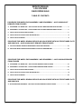
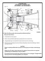
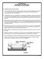
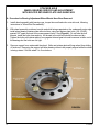
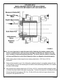
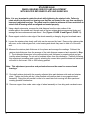
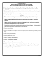
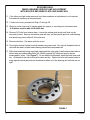
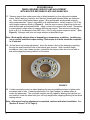
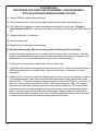
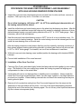
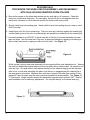
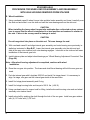
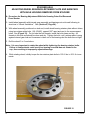
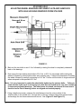
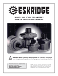
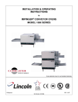
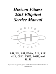
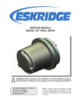
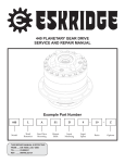
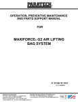
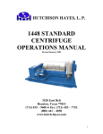
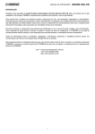
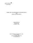
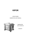
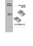
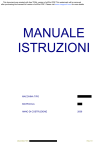
SERVICE MANUAL
L130B / L4130 Series
Logstacker Drive Axle With
Bolt-On Stub End Retainer
Page 1
Allied Form #80-930
Rev 07/2009
SERVICE MANUAL
LOG STACKER
DA202 DRIVE AXLE
TABLE OF CONTENTS
PROCEDURE FOR WHEEL END DISASSEMBLY AND REASSEMBLY – AXLE HOUSING NOT
REMOVED FROM STACKER
A.
DISASSEMBLY OF WHEEL END – AXLE HOUSING HAS NOT BEEN REMOVED FROM STACKER……………..3
B.
REASSEMBLY OF WHEEL END – AXLE HOUSING HAS NOT BEEN REMOVED FROM STACKER……………...4
C.
INSTALLATION OF DUO-CONE FACE SEAL……………………………………………………………………………….6
D.
INSTALLATION OF TORQUE TUBE AND BRAKE DISC…………………………………………………………………..8
E.
INSTALLATION OF WHEEL…………………………………………………………………………………………………….8
PROCEDURE FOR WHEEL BEARING SERVICE AND ADJUSTMENT WITH BOLTED RETAINER PLATE
AND SHIM PACK – AXLE HOUSING NOT REMOVED FROM STACKER
A.
ADJUSTING WHEEL BEARINGS WHEN WHEELS HAVE BEEN REMOVED………………………………………....10
B. ADJUSTING WHEEL BEARINGS WHEN WHEELS HAVE NOT BEEN REMOVED……………………………….…..14
PROCEDURE FOR WHEEL END DISASSEMBLY AND REASSEMBLY – AXLE HOUSING REMOVED
FROM STACKER
A.
DISASSEMBLY OF WHEEL END – AXLE HOUSING REMOVED FROM STACKER………………………………....19
B.
REASSEMBLY OF WHEEL END – AXLE HOUSING REMOVED FROM STACKER…………………………...…......20
C.
INSTALLATION OF DUO-CONE FACE SEAL……………………………………………………………………………....21
D.
INSTALLATION OF TORQUE TUBE AND BRAKE DISC……………………………………………………………...…..23
E.
INSTALLATION OF WHEEL……………………………………………………………………………………………...…....24
PROCEDURE FOR WHEEL BEARING SERVICE AND ADJUSTMENT WITH BOLTED RETAINER PLATE
AND SHIM PACK
A. ADJUSTING WHEEL BEARINGS – WITH AXLE HOUSING REMOVED FROM STACKER…………………………...26
2
7/16/2009
STACKER AXLE
PROCEDURE FOR WHEEL END
DISASSEMBLY AND REASSEMBLY
Internal Gear
Hub
Wheel
Torque Tube
Bolt
Shim Set
Stub End
Adapter-Seal
Plate
Retainer
Cup & Cone
Outer Bearing
Cup & Cone
Inner Bearing
Duo-Cone
Seal
Axle Housing
O-Ring
Brake Caliper
Disc Brake
FIGURE 1
A. Wheel End Disassembly- Axle Housing-Outer End Has Not Been
Removed From Stacker.
1.
Unit should be on level ground.
2.
Block in front and behind wheel that is opposite the side to be worked on.
3.
Using adequate jack, raise wheel off of ground and crib unit at axle housing.
4. Tires and rims must always be removed before attempting to adjust wheel bearings or before
removing the wheel.
CAUTION:
Always completely deflate both tires prior to removing any rim clamps or loosening lug
nuts.
Always check the valve stem to make sure air passage is clear and tires are completely deflated prior to disassembly of rims from wheel.
Run a piece of wire through the valve stem to make sure it is not plugged. Foreign material
may clog the valve stem during deflation or ice may form.
3
7/16/2009
STACKER AXLE
PROCEDURE FOR WHEEL END
DISASSEMBLY AND REASSEMBLY
5. Remove rims with tires.
6. Remove (3) disc brake calipers.
7
Drain oil from planet assembly.
8.
Remove planet carrier cover.
9.
Remove 2nd stage planet assembly.
10. Remove 1st stage planet assembly.
11. Remove axle shaft and sun gear as an assembly.
12. Block up under wheel to support it or attach a lifting device to wheel through slot in OD of wheel.
(Lift device must be able to lift 4,000 lbs.)
13. Remove ¾” bolts, retainer plate and shims.
14. For easier internal gear assembly, removal and installation install Guide Thimble 070-284 onto
outer end of stub end using bolts in threaded holes on the end of stub end.
15. Slide internal gear assembly and outer bearing out of wheel and onto guide tool. Using a forklift or
boom truck, remove internal gear assembly and bearing.
16. With lifting device that is attached to wheel assembly remove wheel from stub end. (Weight is approximately 4,000 lbs.) Set assembly on the ground with torque tube and brake disc up.
17. Remove brake disc, (2) half discs.
18. Remove torque tube.
19. Inspect all parts and replace as necessary.
B. Wheel End Reassembly – Axle Housing – Outer End Has Not Been Removed From
Stacker
1.
Check unit to make sure it is cribbed properly, preferably in two places.
2.
All parts should be cleaned and all oil, grease and rust removed prior to assembly. Clean the inside of the wheel and bearing bores of chips and accumulated dirt that may be trapped in the bearing cavity. It is very important that this area be free of foreign material.
4
7/16/2009
STACKER AXLE
PROCEDURE FOR WHEEL END
DISASSEMBLY AND REASSEMBLY
3. Inspect the axle stub end and internal gear hub for nicks or burrs; remove as needed. Inspect
drilled and tapped holes for metallic chips. Blow out drilled holes, if necessary, to ensure
cleanliness.
4. Inspect the Duo-Cone seal retainer and bearing spacer located on the stub end and replace if
required. To install seal retainer, clean stub end surface and inner surface of seal retainer with
Loctite Cleaner #7070. Coat inside surface of retainer ring with Locktite #7649 Primer N. Let dry
for 30 seconds. Place retainer in rod oven and heat to 100 degrees. Check with heat gun to verify
100 degrees. Apply a light coat of Locktite 620 Retaining Compound on the stub end surface for
1/3 the width of the retainer and only on the leading edge from where the retainer will be positioned
when fully in place. Use only a light coat and only at the leading edge. When installing the retainer
the Locktite will wick under the retainer. If too much Locktite is applied the retainer will push too
much of it back to where it will interfere with the retainer seating against the shoulder.
5. Inspect the inner and outer wheel bearing bores and seal bore for nicks and burrs; remove as
required. Chill cups in dry ice for 15 minutes or in a freezer.
CAUTION:
Do not allow bearings to chill below -40 Fahrenheit. At -65o Fahrenheit the
metallurgical characteristics of the bearing material will be altered.
o
6. Install the chilled inner and outer bearing cups in the wheel into the bearing cup bores. After the
temperatures have stabilized ensure that cups are fully seated by checking a minimum of three
places between bearing cups and backing shoulder with a .001” or .0015” feeler gauge. Seat, if
necessary, with soft bar and hammer.
7. Heat the outer and inner wheel bearing cones to 250o F (in hot oil or in an induction oven). Do not
use a torch for heating bearings. Install the outer bearing cone on the internal gear hub and install
the inner bearing cone on the stub end.
After the bearing cones are cooled ensure that they are fully seated by checking a minimum of three
places between bearing and backing shoulder on internal gear hub and on stub end with a .001”
or .0015” feeler gauge. If not seated, use a soft bar and hammer to seat them.
8. With both inner and outer bearing cones installed prelube the bearings with Lubriplate 3000W
lubricant.
9. Proceed with installation of Duo-Cone face seal. See (Section C, PAGE 6).
5
7/16/2009
STACKER AXLE
PROCEDURE FOR WHEEL END
DISASSEMBY AND REASSEMBLY
C.
Installation of Duo-Cone Face Seal
1.
Face ring (Duo-Cone) seals have highly finished surfaces and are held together by toric sealing
rings. The flexibility of the toric sealing rings makes the floating ring seals self aligning and
compensates for wear on the metal faces.
2.
Install seals with care to not damage them in handling and on installation. Always install the metal
Duo-Cone rings in matched pairs; that is, two new rings together or two rings that have previously
run together. When installing new seals do not intermix the metal rings as they are match ground
in pairs.
3. Remove all oil or protective coating from Duo-Cone metal rings and from the ramps on the wheel,
and on the seal retainer and dry them. Use one of the approved assembly lubricants (listed at the
end of this section) as a cleaning agent. Do not use any other liquid that leaves an oily film or does
not evaporate quickly.
4. Be sure the ramps on the wheel, and retainer are dry and that no oil is present. Check the ramps
for rough marks and nicks. On used parts, remove all dirt or rust deposits from the ramps with a
scraper or wire brush and smooth the surface with emery cloth.
5. Always install new toric sealing rings. Never install a used toric sealing ring on a new or used DuoCone seal.
6. Install torics onto Duo-Cone metal rings. The toric must rest uniformly against the retaining lip and
the flashing line of the toric must be straight and parallel (not twisted) with the retaining lip.
7. Use seal installation tool 075-007 to install one half of the Duo-Cone seal assembly into seal ramp
on wheel. Wet the lower half of the toric in approved lubricant by dipping or brushing on with a
clean foam brush, or wiping on with a lint free cloth. See Figure 2.
FIGURE 2
6
7/16/2009
STACKER AXLE
PROCEDURE FOR WHEEL END
DISASSEMBY AND REASSEMBLY
While still wet, quickly press seal assembly into the wheel with the seal installation tool. Seating
the seal into wheel may require tapping on the tool lightly with a rubber mallet. Be careful to not
twist the toric. On large seals it may require starting on one side and tapping on the opposite side
of tool to push seal assembly into place until the toric is engaged past the retaining lip of the seal
ramp on the wheel. Measure from seal face of wheel to the seal face surface in four places 90
degrees apart to make sure the seal is correctly installed (must be parallel). See Figure 3.
“A” Dimension. Height variation around the assembled ring should not exceed .040”. Use the seal
installation tool to make any adjustments. Do not push directly on the metal seal ring.
8.
Repeating the basic procedure as outlined in item No. C.7, use seal installation tool 075-007 to
install one half of the Duo-Cone seal assembly onto the seal retainer located on the axle stub end.
9.
Before assembling the wheel to the stacker axle, wipe the faces of the seal with a lint free cloth to
remove any foreign material. Put a thin film of clean oil on the seal faces. Be careful to not let any
oil come in contact with the toric or its mating surface.
FIGURE 3
Approved Assembly Lubricants
Isopropyl Alcohol*
Houghto-Grind 60 CT
Quaker Solvo Clean 68*All applicable safety and disposal guidelines for flammable liquids must be followed.
7
7/16/2009
STACKER AXLE
PROCEDURE FOR WHEEL END
DISASSEMBLY AND REASSEMBLY
D. Installation Of Torque Tube and Brake Disc
1.
Clean mating surfaces of wheel and torque tube of all paint, burrs, etc., to ensure torque tube
has full contact.
2.
Turn wheel upside down with planet adapter towards bottom.
3.
Position torque tube over wheel and align all bolt holes while lowering tube to wheel.
4.
Install bolts with anti-seize compound and torque in criss-cross pattern to 680 ft. lbs. (+68/-0).
5.
Install first half of brake disc.
6.
Install bolts and washers using Locktite #242 and torque to 280 ft. lbs.(+28/-0).
7.
Install second half of brake disc and repeat bolt installation process.
8. Do not mount the brake calipers until after the wheel has been installed and wheel bearing
adjustment has been completed.
E.
Wheel Installation
1. Make sure unit is safely cribbed.
2. The wheel, torque tube and disc brake assembly may be carried by forklift or by sling and
overhead crane during installation. It is suggested that Guide Thimble, 070-284 bolted onto the end
of the stub end be used to aid in alignment of the wheel on stub end during wheel mounting. Lift
wheel, torque tube and disc brake assembly and slide it over the stub end until the inner bearing
seats on the stub end.
CAUTION:
When installing the heavy wheel, torque tube and brake disc on the stub end use extreme
care to ensure that the wheel is maintained in a level position and centered in relation to the
axle. Failure to do so may result in damage to a seal.
CAUTION:
Do not bang wheel into place on the stub end. This can damage the seal.
8
7/16/2009
STACKER AXLE
PROCEDURE FOR WHEEL END
DISASSEMBLY AND REASSMBLY
3. With the wheel still supported in a level position, use overhead crane to lift and align the internal
gear assembly and outer bearing cone previously installed as instructed in Section B, Item 7
(PAGE 5). Install the internal gear assembly with outer bearing cone using guide tool and slide
all the way onto stub end until bearing engages. Lubricant on the stub end will ease installation
of the internal gear hub.
4. Install retainer plate without shims using two retainer plate bolts, (3/4-10UNC), spaced
180o apart and next to the measurement holes. See FIGURE 4 (PAGE 10). Tighten the bolts
until retainer plate is snug against internal gear hub and looseness is taken out of the bearings
but the bolts are not tight.
5. Remove sling and overhead crane or support from underneath the wheel. Bolts and retainer plate will keep wheel from sliding off stub end. Removing support will allow bearing rollers to be properly aligned while the wheel is being rotated.
6. Adjust wheel bearings and complete final installation of the retainer plate per “Wheel
Bearing Adjustment Procedure.” See (PAGE 10).
Note: After wheel bearing adjustment is completed, continue with wheel installation.
7. Install axle shaft and sun gear as an assembly.
8. Pre-lube internal gear with Lubriplate 3000-W and install 1st stage planet. Remove the 7/8”
sun gear retaining bolt. Insert a bar into the open bolt hole in the axle shaft and lift the axle and
the sun gear for aligning the gear teeth of the sun gear, 1st stage planet and internal gear at
the same time.
9. Install 2nd stage planet assembly and O-ring.
10. Install 2nd stage housing bolts and torque to 280 ft. lbs. (+28/-0).
11. Reinstall 7/8” sun gear retaining bolt previously removed in Step #8.
12. Install planet carrier cover and sun gear cover plate.
13. Mount the (3) brake calipers.
14. Mount tires and rims.
15. Fill wheel to oil level with recommended lubricant.
9
7/16/2009
STACKER AXLE
WHEEL BEARING SERVICE AND ADJUSTMENT
WITH BOLTED RETAINER PLATE AND SHIM PACK
A. Procedure for Bearing Adjustment When Wheels Have Been Removed.
1.
Install wheel assembly with bearing cups, torque tube and brake disc onto stub end, following
instructions in “Wheel End Re-assembly”.
2.
With wheel assembly positioned on stub end while being supported on the underneath outer edge,
install wheel bearing retainer plate without shims, using two retainer plate bolts, (3/4-10UNC),
spaced 180o apart and next to the measurement holes. See (Figure 4). Do not lube the bolt
threads, install the bolts clean and dry. All threads in the stub end should be clean and dry.
Tighten the bolts until retainer plate is snug against internal gear hub and looseness is taken out of
the bearings but the bolts are not tight.
3.
Remove support from underneath the wheel. Bolts and retainer plate will keep wheel from sliding
off stub end. Removing the support will allow bearing rollers to be properly aligned while the wheel
is being rotated. Roll the wheel 3 to 5 revolutions.
FIGURE 4
10
7/16/2009
STACKER AXLE
WHEEL BEARING SERVICE AND ADJUSTMENT
WITH BOLTED RETAINER PLATE AND SHIM PACK
Internal Gear
Hub
FIGURE 5
Note: It is very important to rotate the wheel while tightening the bearing retainer bolts.
Failure to rotate wheels could result in a bearing cone that has not seated in the cup,
thus resulting in improperly adjusted bearings. The wheel must be rotated a minimum
of three revolutions to ensure that all bearing rollers are aligned and seated properly.
4.
While rotating wheel, initially torque the two retainer plate bolts to 150 ft. lbs. in 25 ft. lb.
increments.
5.
Back out the two bolts to zero ft. lbs. followed by rotating the wheel to completely release all load
on the bearings. Be sure the internal gear hub and the outboard bearing slide back out to release
all load on the bearings.
6. Now torque the two retainer plate bolts to 60 ft. lbs. in 20 ft. lb. increments while rotating the wheel
or followed by wheel rotation after each torquing step. Continue the sequence of rotating the wheel
followed by carefully retorquing to 60 ft. lbs. Do this until the two bolts no longer advance when
retorqued to the specified 60 ft. lbs.
11
7/16/2009
STACKER AXLE
WHEEL BEARING SERVICE AND ADJUSTMENT
WITH BOLTED RETAINER PLATE AND SHIM PACK
Note: It is very important to rotate the wheel while tightening the retainer bolts. Failure to
rotate wheels could result in a bearing cone that has not seated in the cup, thus resulting in
improperly adjusted bearings. The wheel must be rotated a minimum of three revolutions to
ensure that all bearing rollers are aligned and seated properly.
7. Using a depth micrometer, measure the total distance from the outer surface of the
retainer plate to the spindle end, through each of the two retainer plate measurement holes and
average the two measurements and record. See (Figure 4. PAGE 10 and Figure 5, PAGE 11).
8. Place support under the outer edge of the wheel assembly or hang by sling and overhead crane.
9. Loosen the retainer plate slowly until bolts can be removed by hand. Remove the retainer plate
with care, as the internal gear hub, outer bearing and wheel may want to slide off of the stub
end.
10. Measure the retainer plate thickness in four places and average the readings. Subtract the
retainer plate thickness from the average of the total distance measured and recorded in Step
7. The subtracted dimension is the required shim pack thickness to properly adjust and preload the wheel bearings. Do not add or subtract shims from this dimension. Carefully following
this adjustment procedure and correctly selecting the correct shim pack thickness as instructed
will result in the correct .004 to .005 bearing preload.
Note: This adjustment procedure and preload values are the same for new and used
bearings.
11. Re-install retainer plate with the properly adjusted shim pack between stub end and retainer
plate. Tighten two bolts with dry, clean threads until retainer plate is snug against wheel
assembly. Doing this will prevent Loctite to be used later from running into shim pack and
creating possible interference.
12. Remove support from under outer edge of wheel assembly or from sling and overhead crane.
12
7/16/2009
STACKER AXLE
WHEEL BEARING SERVICE AND ADJUSTMENT
WITH BOLTED RETAINER PLATE AND SHIM PACK
13. Before applying Loctite be sure that bolt threads and threaded holes are clean and dry. Clean
them using brake cleaner solvent. Blow bolt threads and threaded holes dry using
compressed air. Apply Loctite #262 to all additional bolts. Initially torque to 120 ft. lbs. using
torque sequence shown in (Figure 6, PAGE 13). Next be sure to remove original two bolts
and clean bolt threads and threaded holes. Apply Loctite to the original bolts as well.
Remember to rotate wheel to align rollers in bearings as bolts are torqued. Now continue
torquing all bolts in 40 ft. lbs. increments to final 280 ft. lbs. (+28/-0) using torque sequence
shown. Retorque until bolts no longer move at specified torque.
Note: Work rapidly without delay as depending on temperature conditions. Locktite may
set up quickly and affect torque reading. Final torque of all bolts should be completed
in 10 minutes.
14. As final check on bearing adjustment check the bottom rollers of the bearing by reaching
through the small inspection hole in the internal gear trunion. With a medium length
screwdriver, (don’t use a heavy pry bar) check that the bottom rollers do not move side to side
without applying heavy pressure on the rollers.
15. If rollers are easily moved, re-adjust bearings by removing additional shims to tighten roller
movement side to side. If bearing adjustment is too tight, readjust by adding shims to loosen the
adjustment. The over-tight condition can be judged by bearings so tight that you are unable to
rotate the wheel with your full body weight when stepping/climbing on the wheel casting cutouts.
Note: After wheel bearing adjustment is completed, continue with wheel installation. See
(Section E, Items 7 to 15, Page 9).
FIGURE 6
13
7/16/2009
STACKER AXLE
WHEEL BEARING SERVICE AND ADJUSTMENT
WITH BOLTED RETAINER PLATE AND SHIM PACK
B.
Procedure for Checking and Adjusting Wheel Bearings When Wheels Have Not Been
Removed .
1.
Stacker should be on level ground with wheels chocked in front and behind wheel that is opposite
the side to be worked on.
2. Using adequate jack, raise stacker wheel off ground and crib under stacker axle housing.
CAUTION:
Tires and rims must always be removed before attempting to adjust wheel bearings.
Always completely deflate both tires prior to removing any rim clamps or loosening
lug nuts.
Always check the valve stem to make sure air passage is clear and tires are completely
deflated prior to disassembly of rims from wheels.
Run a piece of wire through the valve stem to make sue it is not plugged. Foreign material
may clog the valve stem during deflation or ice may form.
3. Remove rims with tires.
4. Remove the (3) disc brake calipers or back off all caliper pistons to eliminate any possibility of brake
drag.
5. Drain oil from planet assembly.
6. Remove planet carrier cover.
7. Remove 2nd stage planet assembly.
8. Remove 1st stage planet assembly.
9. Remove axle shaft with sun gear as an assembly.
10. With the wheel raised and no support under it check the bottom rollers of the outboard bearing
cone by reaching through the small inspection hole in the internal gear trunnion. With a small
screwdriver (don’t use a heavy pry bar) check that the bottom rollers do not move side to side
without applying heavy pressure on the rollers.
14
7/16/2009
STACKER AXLE
WHEEL BEARING SERVICE AND ADJUSTMENT
WITH BOLTED RETAINER PLATE AND SHIM PACK
11. If the rollers are tight under pressure from the screwdriver an adjustment is not required.
Proceed with replacing all removed parts.
12. If rollers are loose, proceed with Step 13 through 29.
13 Block up under outer end of stacker wheel for support or use sling and overhead crane.
(Lift device must be able to lift 4,000 lbs).
14. Remove 3/4” bolts from retainer plate. Loosen the retainer plate slowly until bolts can be
removed by hand. Remove the retainer pate with care, as the internal gear hub, outer bearing
and wheel may want to slide off of the stub end.
15. Remove all shims. Set shims aside for re-use.
16. Thoroughly clean all Loctite from bolt threads using wire brush. Run tap into threaded holes in
stub end and wash out with brake cleaning solvent and compressed air.
17. With wheel assembly being supported underneath the outer edge, install retainer plate without
shims using two retainer plate bolts (3/4-10UNC) spaced 180o apart and next to the two
measurement holes. See (Figure 7). Do not lube the bolt threads, install the bolts clean and
dry. All threads in the stub end must be clean and dry. Tighten the bolts until retainer plate is
snug against internal gear hub and looseness is taken out of the bearings but the bolts are not
tight.
FIGURE 7
15
7/16/2009
STACKER AXLE
WHEEL BEARING SERVICE AND ADJUSTMENT
WITH BOLTED RETAINER PLATE AND SHIM PACK
Internal Gear
Hub
FIGURE 8
18. Remove support from underneath the wheel. Bolts and retainer plate will keep wheel from
sliding off stub end. Removing the support will allow bearing rollers to be properly aligned while
the wheel is being rotated. Roll the wheel 3 to 5 revolutions.
Note: It is very important to rotate the wheel while tightening the bearing retainer bolts.
Brakes must not be dragging during wheel rotation. Refer to Section B, item 4. Failure to
rotate wheels could result in improperly adjusted bearings.
19. While rotating wheel, initially torque the two retainer plate bolts to 150 ft. lbs. in 25 ft. lb.
increments.
20. Back out the two bolts to zero ft. lbs., followed by rotating the wheel to completely release all
load on the bearings. Be sure the internal gear hub and the outboard bearing slide back out to
release all load on the bearings.
16
7/16/2009
STACKER AXLE
WHEEL BEARING SERVICE AND ADJUSTMENT
WITH BOLTED RETAINER PLATE AND SHIM PACK
21. Now torque the two retainer plate bolts to 60 ft. lbs. in 20 ft. lb. increments while rotating the
wheel or followed by wheel rotation after each torquing step. Continue the sequence of
rotating the wheel followed by carefully retorquing to 60 ft. lbs. Do this until the two bolts no
longer advance when retorqued to the specified 60 ft. lbs.
Note: It is very important to rotate the wheel while tightening the retainer bolts. Failure to
rotate wheels could result in a bearing cone that has not seated in the cup, thus
resulting in improperly adjusted bearings. The wheel must be rotated a minimum of
three revolutions to ensure that all bearing rollers are aligned and seated properly.
22. Using a depth micrometer, measure the total distance from the outer surface of the retainer plate
to the spindle end, through each of the two retainer plate measurement holes and average the
two measurements and record. See (Figure 7, PAGE 15 and Figure 8, PAGE 16).
23. Place support under the outer edge of the wheel assembly or hang by sling and overhead crane.
24. Loosen the retainer plate slowly until bolts can be removed by hand. Remove the retainer plate
with care, as the internal gear hub, outer bearing and wheel may want to slide off of the stub
end.
25. Measure the retainer plate thickness in four places and average the readings. Subtract the
retainer plate thickness from the average of the total distance measured and recorded in Step 22.
The subtracted dimension is the required shim pack thickness to properly adjust and preload the
wheel bearings. Do not add or subtract shims from this dimension. Carefully following this
adjustment procedure and correctly selecting the correct shim pack thickness as instructed will
result in the correct .004 to .005 bearing preload.
Note: This adjustment procedure and preload values are the same for new and used
bearings.
26. Re-install retainer plate with the properly adjusted shim pack between stub end and retainer
plate. Tighten two bolts with dry, clean threads until retainer plate is snug against wheel
assembly. Doing this will prevent Loctite to be used later from running into shim pack and
creating possible interference.
17
7/16/2009
STACKER AXLE
WHEEL BEARING SERVICE AND ADJUSTMENT
WITH BOLTED RETAINER PLATE AND SHIM PACK
27. Remove support from under outer edge of wheel assembly or from sling and overhead
crane. Before applying Loctite by sure that bolt threads and threaded holes are clean and
dry. Clean them using brake cleaner solvent. Blow bolt threads and threaded holes dry
using compressed air. Apply Loctite #262 to all additional bolts. Initially torque to 120 ft. lbs.
using torque sequence shown in (Figure 9). Next be sure to remove original two bolts and
clean bolt threads and threaded holes. Apply Loctite to the original bolts as well. Remember
to rotate wheel to align rollers in bearings as bolts are torqued. Now continue torquing all
bolts in 40 ft. lb. increments to final 280 ft. lbs. (+28/-0) using torque sequence shown. (See
Figure 9). Retorque until bolts no longer advance at specified torque.
Note: Work rapidly without delay as depending on temperature conditions, Locktite may
set up quickly and affect torque reading. Final torque of all bolts should be completed
in 10 minutes.
28. As final check on bearing adjustment, check the bottom rollers of the bearing by reaching
through the small inspection hole in the internal gear trunnion. With a medium length
screwdriver, (don’t use a heavy pry bar) check that the bottom rollers do not move side to
side without applying heavy pressure on the rollers.
FIGURE 9
29. If rollers are easily moved, re-adjust bearings by removing additional shims to tighten roller
movement side to side. If bearing adjustment is too tight, readjust by adding shims to
loosen the adjustment. The over-tight condition can be judged by bearings so tight that you
are unable to rotate the wheel with your full body weight when stepping/climbing on the wheel
casting cutouts.
Note: After wheel bearing adjustment is completed, continue with wheel installation. See
(Section E, items 7 to 15, Page 9).
18
7/16/2009
STACKER AXLE
PROCEDURE FOR WHEEL END DISASSEMBLY AND REASSEMBLY
WITH AXLE HOUSING REMOVED FROM STACKER
A. Wheel End Disassembly-With Axle Housing-Outer End Removed From Stacker.
1. Unit should be on level ground.
2. Block in front and behind wheel that is opposite the side to be worked on.
3. Using adequate jack, raise wheel off of ground and crib unit inboard of Axle Housing-Outer End.
CAUTION:
Always completely deflate both tires prior to removing any rim clamps or loosening lug
nuts.
Always check the valve stem to make sure air passage is clear and tires are completely
deflated prior to disassembly of rims from wheel.
Run a piece of wire through the valve stem to make sure it is not plugged. Foreign material
may clog the valve stem during deflation or ice may form.
4. Remove rims with tires.
5. Remove (3) disc brake calipers.
6. Drain lube from wheel.
7. Remove cover plate-sun gear and cover-planet carrier.
8. Remove (1) 7/8” bolt and (4) 1/2 “ bolts from sun gear retainer and remove sun gear retainer.
9. Remove axle shaft by pulling the shaft through the sun gear hub leaving the sun gear in place.
10. Using overhead crane for support and for lifting, remove axle housing outer end and wheel from
stacker frame.
(Lift device must be able to lift 8,000 to 10,000 lbs.)
11. Position axle housing and wheel in vertical position with axle housing base end down and wheel up.
12. Using overhead crane remove 2nd stage planet assembly.
13. Remove 1st stage planet assembly.
19
7/16/2009
STACKER AXLE
PROCEDURE FOR WHEEL END DISASSEMBLY AND REASSEMBLY
WITH AXLE HOUSING REMOVED FROM STACKER
14. Remove 3/4 bolts, retainer plate and shims.
15. Using overhead crane, remove internal gear assembly along with outer bearing cone.
16. With lifting device attached to wheel assembly remove wheel from stub end. (Weight is
approximately 4,000 lbs.) Set wheel assembly on the ground with torque tube and brake disc
up.
17. Remove brake disc, (2) half discs.
18. Remove torque tube.
19. Inspect all parts and replace as necessary.
B. Wheel End Reassembly With Axle Housing Outer End Removed From Stacker.
1. All parts should be cleaned and all oil, grease and rust removed prior to assembly. Clean the
inside of the wheel and bearing bores of chips and accumulated dirt that my be trapped in the
bearing cavity. It is very important that this area be free of foreign material.
2. Position axle housing-outer end with base on floor, stub end up.
3. Inspect the axle stub end and internal gear hub for nicks or burrs; remove as needed. Inspect
drilled and tapped holes for metallic chips. Blow out drilled holes, if necessary, to ensure
cleanliness.
4. Inspect the Duo-Cone seal retainer and bearing spacer on the stub end and replace if required.
To install seal retainer, clean stub end surface and inner surface of seal retainer with Loctite
Cleaner #7070. Coat inside surface of retainer ring with Loctite #7649 Primer N. Let dry for 30
seconds. Place in rod oven and heat to 100oF. Check with heat gun to verify 100o. Apply a
light coat of Locktite 620 retaining compound on the stub end surface for 1/3 the width of the
retainer and only on the leading edge from where the retainer will be positioned when fully in
place. Use only a light coat and only at the leading edge. When installing the retainer the
Loctite will wick under the retainer. If too much Locktite is applied the retainer will push it back
to where it will interfere with the retainer seating against the shoulder.
20
7/16/2009
STACKER AXLE
PROCEDURE FOR WHEEL END DISASSEMBLY AND REASSEMBLY
WITH AXLE HOUSING REMOVED FROM STACKER
5. Inspect the inner and outer wheel bearing bores and seal bore for nicks and burrs: remove as
required. Chill cups in dry ice for 15 minutes or in a freezer.
CAUTION:
Do not allow bearings to chill below -40oF. At –65oF the metallurgical characteristics of
the bearing material will be altered.
6. Install the chilled inner and outer bearing cups in the wheel into the bearing cup bores. After the
temperatures have stabilized ensure that cups are fully seated by checking a minimum of three
places between bearing cups and backing shoulder with a .001” or .0015” feeler gauge. Seat, if
necessary, with soft bar and hammer.
7. Heat the outer and inner wheel bearing cones to 250oF (in hot oil or in an induction oven). Do
not use a torch for heating bearings. Install the outer bearing cone on the internal gear hub and
install the inner bearing cone on the stub end.
After the bearing cones are cooled ensure that they are fully seated by checking a minimum of
three places between bearing and backing shoulder on internal gear hub and on stub end with
a .001” or .0015” feeler gauge. If not seated, use a soft bar and hammer to seat them.
8. With both inner and outer bearing cones installed prelube the bearings with Lubriplate 3000W.
lubricant.
9. Proceed with installation of Duo-cone face seal.
C. Installation of Duo-Cone Face Seal
1. Face ring (Duo-Cone) seals have highly finished surfaces and are held together by toric sealing
rings. The flexibility of the toric sealing rings makes the floating ring seals self aligning and
compensates for wear on the metal faces.
2. Install seals with care to not damage them in handling and on installation. Always install the
metal Duo-Cone rings in matched pairs; that is, two new rings together or two rings that have
previously run together. When installing new seals do not intermix the metal rings as they are
match ground in pairs.
3. Remove all oil or protective coating from Duo-Cone metal rings and from the ramps on the
wheel and on the seal retainer and dry them. Use one of the approved assembly lubricants
(listed at the end of this section) as a cleaning agent. Do not use any other liquid that leaves an
oily film or does not evaporate quickly.
21
7/16/2009
STACKER AXLE
PROCEDURE FOR WHEEL END DISASSEMBLY AND REASSEMBLY
WITH AXLE HOUSING REMOVED FROM STACKER
4. Be sure the ramps on the wheel and retainer are dry and that no oil is present. Check the
ramps for rough marks and nicks. On used parts, remove all dirt or rust deposits from the
ramps with a scraper or wire brush and smooth the surface with emery cloth.
5. Always install new toric sealing rings. Never install a used toric sealing ring on a new or used
Duo-Cone seal.
6. Install torics onto Duo-Cone metal rings. The toric must rest uniformly against the retaining lip
and the flashing line of the toric must be straight and parallel (not twisted) with the retaining lip.
7. Use seal installation tool 075-007 to install one half of the Duo-Cone seal assembly into seal
ramp on wheel. Wet the lower half of the toric in approved lubricant by dipping or brushing on
with a clean foam brush or wiping on with a lint free cloth. See Figure 10.
Figure 10
While still wet, quickly press seal assembly into the wheel with the seal installation tool. Seating
the seal into wheel may require tapping on the tool lightly with a rubber mallet. Be careful to not
twist the toric. On large seals it may require starting on one side and tapping on the opposite
side of tool to push seal assembly into place until the toric is engaged past the retaining lip of
the seal ramp on the wheel. Measure from seal face of wheel to the seal face surface in four
places 90o apart to make sure the seal is correctly installed (must be parallel). See Figure 11,
“A” Dimension. Height variation around the assembled ring should not exceed .040.” Use the
seal installation tool to make any adjustments. Do not push directly on the metal seal ring..
Figure 11
22
7/16/2009
STACKER AXLE
PROCEDURE FOR WHEEL END DISASSEMBLY AND REASSEMBLY
WITH AXLE HOUSING REMOVED FROM STACKER
8. Repeating the basic procedure as outlined in item No. C. 7, use seal installation tool 075-007 to
install one half of the Duo-Cone seal assembly onto the seal retainer located on the axle stub
end.
9. Before assembling the wheel to the stacker axle, wipe the faces of the seal with a lint free cloth
to remove any foreign material. Put a thin film of clean oil on the seal faces. Be careful to not
let any oil come in contact with the toric or it’s mating surface.
Approved Assembly Lubricants
Isopropyl Alcohol*
Houghto-Grind 60 CT
Quaker Solvo Clean 68-0
*All applicable safety and disposal guidelines for flammable liquids must be
followed.
D. Installation of Torque Tube And Brake Disc
1. Clean mating surface of wheel and torque tube of all paint and burrs to ensure torque tube has
full contact.
2. Turn wheel upside down with planet adapter towards bottom.
3. Position torque tube over wheel and align all bolt holes while lowering tube to wheel.
4. Install bolts with anti-seize compound and torque in criss-cross pattern to 680 ft. lbs. (+68/-0).
5. Install first half of brake disc.
6. Install bolts and washers using Locktite #242 and torque to 280 ft. lbs. (+28/-0).
7. Install second half of brake disc and repeat bolt installation process.
8. Do not mount the brake calipers until after wheel installation and wheel bearing adjustment has
been completed and axle housing-outer end has been installed on stacker frame.
23
7/16/2009
STACKER AXLE
PROCEDURE FOR WHEEL END DISASSEMBLY AND REASSEMBLY
WITH AXLE HOUSING REMOVED FROM STACKER
E. Wheel Installation
1. Using overhead crane lift wheel, torque tube and disc brake assembly and lower it carefully over
the stub end and slide it over the stub end until the inner bearing seats on the stub end.
CAUTION:
When installing the heavy wheel, torque tube and brake disc on the stub end use extreme
care to ensure that the wheel is maintained in a level position and centered in relation to
the axle. Failure to do so may result in damage to a seal.
CAUTION:
Do not bang wheel into place on the stub end. This can damage the seal.
2. With overhead crane lift and align internal gear assembly and outer bearing cone previously installed as instructed in Step B #7. Lower the internal gear assembly onto the stub end and
slide all the way onto stub end until outer bearing engages. Lubricant on the stub end will ease
installation of the internal gear hub.
3. Install retainer plate and adjust wheel bearings per “Wheel Bearing Adjustment Procedure” See
(Page 26).
Note: After wheel bearing adjustment is completed, continue with wheel
installation.
4. Place the sun gear into position. The brass axle shaft thrust bearing will hold the sun gear centered.
5. Pre-lube internal gear with Lubriplate 3000-W and install 1st stage planet. It is necessary to
align 1st stage, sun gear and the internal gear teeth at the same time.
6. Install 2nd stage planet assembly and O-ring.
7. Install 2nd stage housing bolts and torque to 280 ft. lbs. (+28/-0).
8. Using overhead crane for support and for lifting, install entire axle housing outer end and wheel
assembly onto stacker frame.
9. Install axle shaft by pushing the shaft through the hub of the sun gear. Install sun gear retainer
with (4) 1/2” bolts and (1) 7/8” bolt.
24
7/16/2009
STACKER AXLE
PROCEDURE FOR WHEEL END DISASSEMBLY AND REASSEMBLY
WITH AXLE HOUSING REMOVED FROM STACKER
10. Install planet carrier cover and sun gear cover plate.
11. Mount the (3) brake calipers.
12. Mount the tires and rims.
13. Fill wheel to oil level with recommended lubricant.
25
7/16/2009
STACKER AXLE
ADJUSTING WHEEL BEARINGS-RETAINER PLATE AND SHIM PACK
WITH AXLE HOUSING REMOVED FROM STACKER
A. Procedure for Bearing Adjustment With Axle Housing Outer End Removed
From Stacker
1. Install wheel assembly with internal gear assembly and bearings onto stub end following instructions in “Wheel Installation.” See (Section E, Page 24).
2. With wheel assembly positioned on stub end, install wheel bearing retainer plate without shims,
using two retainer plate bolts, (3/4-10UNC), spaced 180o apart and next to the measurement
holes. See (Figure 12). Do not lube the bolt threads, install the bolts clean and dry. All
threads in the stub end should be clean and dry. Tighten the bolts until retainer plate is snug
against internal gear hub and looseness is taken out of the bearings but the bolts are not tight.
3. Roll the wheel 3 to 5 revolutions.
Note: It is very important to rotate the wheel while tightening the bearing retainer bolts.
Failure to rotate wheels could result in a bearing cone that has not seated in the
cup, thus resulting in improperly adjusted bearings.
4. While rotating wheel, initially torque the two retainer plate bolts to 150 ft. lbs. in 25 ft. lb. increments.
FIGURE 12
26
7/16/2009
STACKER AXLE
ADJUSTING WHEEL BEARINGS-RETAINER PLATE AND SHIM PACK
WITH AXLE HOUSING REMOVED FROM STACKER
Internal Gear
Hub
FIGURE 13
5. Back out the two bolts to zero ft. lbs. followed by rotating the wheel to completely release all
load on the bearings.
6. Now torque the two retainer plate bolts to 60 ft. lbs. in 20 ft. lb. increments while rotating the
wheel or followed by wheel rotation after each torquing step. Continue the sequence of rotating
the wheel followed by carefully retorquing to 60 ft. lbs. Do this until the bolts no longer advance
when retorqued to the specified 60 ft. lbs.
Note: It is very important to rotate the wheel while tightening the retainer bolts. Failure to
rotate wheels could result in a bearing cone that has not seated in the cup, thus resulting
in improperly adjusted bearings. The wheel must be rotated a minimum of three revolutions to ensure that all bearing rollers are aligned and seated properly.
7. Using a depth micrometer, measure the total distance from the outer surface of the
retainer plate to the spindle end, through each of the two retainer plate measurement holes
and average the two measurements and record. See (Figure 12 and Figure 13).
27
7/16/2009
STACKER AXLE
ADJUSTING WHEEL BEARINGS-RETAINER PLATE AND SHIM PACK
WITH AXLE HOUSING REMOVED FROM STACKER
8. Loosen the bearing retainer plate bolts and remove the bearing retainer plate.
9. Measure the retainer plate thickness in four places and average the readings. Subtract the retainer plate thickness from the average of the total distance measured and recorded in Step 7.
The subtracted dimension is the required shim pack thickness to properly adjust and preload
the wheel bearings. Do not add or subtract shims from this dimension. Carefully following this
adjustment procedure and correctly selecting the correct shim pack thickness as instructed will
result in the correct .004 to .005 bearing preload.
Note: This adjustment procedure and preload values are the same for new and used
bearings.
10. Re-install bearing retainer plate with the properly adjusted shim pack between stub end and
retainer plate. Tighten two bolts with dry, clean threads until retainer plate is snug against
wheel assembly. Doing this will prevent Loctite to be used later from running into shim pack
and creating possible interference.
11. Before applying Loctite be sure that bolt threads and threaded holes are clean and dry. Clean
them using brake cleaner solvent. Blow bolt threads and threaded holes drying using compressed air . Apply Locttite #262 to all additional bolts. Initially torque to 120 ft. lbs. using
torque sequence shown in (Figure 14, PAGE 29).
Note: Remember to rotate wheel to align rollers in bearings as bolts are torqued.
Next be sure to remove original two bolts and clean bolt threads and threaded holes. Apply
Loctite to the original bolts as well. Now continue the sequence of rotating the wheel and
torquing all bolts in 40 ft. lb. increments to final 280 ft. lbs. (+28/-0), using torque sequence
shown. Retorque until bolts no longer advance at specified torque.
Note: Work rapidly without delay as depending on ambient temperature conditions, Locktite
may set up quickly and affect torque reading. Final torque of all bolts should be completed in 10 minutes.
12. As final check on bearing adjustment check the rollers of the outer bearing by reaching
through the small inspection hole in the internal gear trunnion. With a medium length screwdriver, (don’t use a heavy pry bar) check that the rollers do not move side to side without applying heavy pressure on the rollers.
13. If rollers are easily moved, re-adjust bearings by removing additional shims to tighten roller
movement side to side. If bearing adjustment is too tight, re-adjust by adding shims to loosen
the adjustment. The over-tight condition can be judged by bearings so tight that you are unable to rotate the wheel with the aid of a 5 or 6 ft. bar inserted into the wheel casting cutouts.
28
7/16/2009
STACKER AXLE
ADJUSTING WHEEL BEARINGS-RETAINER PLATE AND SHIM PACK
WITH AXLE HOUSING REMOVED FROM STACKER
FIGURE 14
29
7/16/2009