1
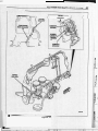
206
MOPAR PERFORMANCE PARTS
Oiling System
INTRODUCTION
The 4.0L engine uses a pressure feed, full flow filtration
oiling system utilizing a gear-type positive displacement
pump is mounted at the underside of the block opposite the
No. 4 main bearing (Figure 4-37). The pump draws oil
through the screen and inlet tube from the sump at the rear
of the oil pan. The oil is driven between the drive and idler
gears and pump body, then forced through the outlet to the
block. An oil galley in the block channels the oil to the inlet
side of the full flow oil filter. After passing through the
filter element, the oil passes from the center outlet of the
filter through an oil galley that channels the oil up to the
main galley which extends the entire length of the block.
The oiling system has a capacity of 5.7L (6 quarts). (For
more oiling system specifications, refer to 4.0L Engine
SpeciJications, ‘Engine Assembly’ section of this chapter.)
Galleys extend downward from the main oil galley to the upper
shell of each main bearing. The crankshaft is drilled internally
to pass oil from the main bearing journals (except No. 4 main
bearing journal) to the connecting rod journals. Each
connecting rod bearing cap has a small squirt hole. Oil passes
through the squirt hole and is thrown off as the rod rotates. This
oil throw-off lubricates the camshaft lobes, camshaft position
sensor drive gear, cylinder walls, and piston pins.
The hydraulic valve tappets receive oil directly from the
main oil galley. Oil is provided to the camshaft bearing
through galleys. The front camshaft bearing journal passes
oil through the camshaft sprocket to the timing chain. Oil
drains back to the oil pan under the No. 1 main bearing cap.
The oil supply for the rocker arms and bridged pivot
assemblies is provided by the hydraulic valve tappets which
pass oil through hollow pushrods to a hole in the
corresponding rocker arm. Oil from the rocker arm
lubricates the valve train components and then passes down
through the pushrod guide holes in the cylinder head, past
the valve tappet area, and returns to the oil pan.
The stock lubrication system will be adequate for normal
passenger car operation. However, in any case where
DaimlerChrysler engines are subjected to unusually high
crankshaft rotational speeds (over 6,000 rpm), acceleration,
deceleration, or cornering loads, special precautions must
be taken with the engine’s oiling system. Not only must an
engine’s oiling system be modified for adequate
lubrication, but it must also be modified to achieve
optimum engine power output.
Troubleshooting
Oiling the valve gear in a standard engine is virtually
automatic, as long as the engine has oil pressure. In a
modified, high performance engine, it can be another story.
When recommendations are followed, most racers will have
no oiling problems. When oiling problems do develop, they
generally manifest themselves as burned pushrod tips,
scuffed valve tips, scuffed and burned rocker arms, broken
pieces, etc. Unfortunately, the pieces that look the worst
usually aren’t the cause of the problem. In the majority of
cases relating to valve gear oiling, it’s not a matter of what
you should do, but what you should not do. The problems
mentioned are the result of poor oiling, assuming the engine
itself is being oiled properly (no foam, no zero psi, etc.).
The first thing to check is that a camshaft bearing hasn’t
“turned” so that its oiling holes aren’t lined up with the
holes in the block. Next, be sure the passage from the
camshaft to the block’s deck isn’t blocked or restricted.
This is usually done with a long handled bottle brush.
At the deck surface of the block, it is common for racers to
install a restrictor. This is not recommended and, if found,
should be removed. If you “smoked out” your pushrods or
scuffed the valve tips, you’ve probably found the cause.
Next, check the head gasket and cylinder head itself for
oiling hole alignment.
At this point you can have two different types of problems
depending on whether your engine uses hydraulic rockers
or mechanical rockers. A problem with hydraulics is most
likely caused by an oil leak that prevents oil from reaching
the rockers. Spacers used between the rocker stand and the
rocker shaft will, over an extended period, cause these
problems because of leakage. Also, the rocker shaft could
be installed incorrectly (upside down, reversed, etc.).
Problems occumng with mechanical rockers can be much
more complicated. Since there is no need to put spacers
between the rocker shaft and the pedestal, a leak there would
be unusual. Rocker shaft installation is very critical. Banana
grooves are usually added to mechanical valve gear rocker
shafts to improve oiling of the rocker itself. Bushed rockers
are more tolerant of low oil conditions, but standard
mechanical rockers should be adequate for most applications.
At this point, with oil to the rocker, it must be distributed to
the valve tip and the pushrod tip. Accomplishing this is very
tricky. Exactly where and how these holes are located is very
critical and each engine is unique.
There is another “trick” with mechanical rockers that should
be considered. The proper (ideal) adjustment for the rocker
adjusting screw is to have only one thread showing below the
rocker arm with the valve lash set properly (two may be okay,
three shaky, etc., but high rpm makes one thread showing the
most desirable). This requires custom length pushrods for
every engine. If you’ve “smoked” your pushrods and you had
all the threads showing below the rocker (i.e., pushrod too
short), more oil to the valve gear won’t cure the problem.
Only longer pushrods will do the job.
TAPPET
GALLERY
Figure 4 - 37
208
MOPAR PERFORMANCE PARTS
OILING SYSTEM PERFORMANCE
CONSIDERATIONS
Choosing the Correct Oiling System
The oiling system to be used on a high performance engine
is determined by the output level of the engine and the type
of application that the engine is going to be used for. Oil
capacity is the first consideration in a basically stock
system used for high performance. This means that the first
step for bracket racing is to deepen the stock pan 2“ along
with lowering the pick-up the same amount. The next step
is a Super Stock race pan and high volume oil pressure
pump. The last step is a dry sump which is particularly
important in oval track and high performance drag race
vehicles that are built low to the ground. During your
engine build-up, after the camshaft has been chosen and the
engine’s application is known, the oiling system type
should be decided on so that any block modification
(especially if a dry sump and roller lifters are to be used)
can be done before the block is assembled and it’s too late.
Oiling System Passage Requirements
It is important to note that oil pump performance at high
engine speeds can be most easily improved by reducing
restrictions on the suction side of the oil pump. Reducing
flow restriction on the suction side of the pump is much
more significant than reducing flow restriction on the
pressure side of the pump. Oil pump suction pipe diameter
should be very generous.
Caution: Modified oil pump suction pick-ups must be
fitted with a protective screen to prevent the pump from
ingesting debris such as metal shavings, broken valve
spring tips, etc.
Oil Flow to Connecting Rod Bearings
For increased oil flow to connecting rod bearings, 360”
fully grooved main bearing sets should be used.
Note: It is NOT recommended that the crankshaft be
grooved because that will weaken the crankshaft.
Oil Restriction
It seems that some magazine article or book is always
recommending that an engine’s oil be restricted in some
way. Some suggestions have no real effect, but those
restricting oil to the upper valve gear can be quite harmful.
We DO NOT recommend restricting oil flow to the upper
valve gear. Leave all the passages stock size and be sure
that they are unobstructed.
The usual result of oil restriction to the upper valve gear is
“smoked out” pushrod tips, scuffed valve tips, scuffed or
burned rockers, or scuffed valve guides. These are
expensive ways to find out what doesn’t work. Full roller
rocker arms can cut down on the valve gear’s oil
requirement but are generally expensive. In racing, as the
rpm is increased, the valve gear needs more oil. If you have
extra time available in your engine building process,
helping the oil in the cylinder head return to the pan can be
beneficial. Helping the oil return past the crankshaft
without getting on to the crankshaft is the best place to
spend your time.
Restricting oil to the tappet galley with roller lifters is a
very common practice (and required for 3.9L V-6 engines
with high lift roller camshafts). However, restricting oil to
the upper valve gear is NOT recommended. The oil is fed
to the upper valve gear through mating passages in the
block and head. Restricting these passages cuts down on the
amount of oil available to the valve gear (valves, rockers,
pushrods). This causes two problems. At.high rpm, rocker
arms like to “shake off’ the oil that is used to lubricate
valves and pushrod tips. In most cases, the engine needs all
its designed oil flow to keep its durability high and to
minimize parts wear. The other problem occurs at low
speed where the oil pressure drops to its minimum. In this
condition, the valve gear, being the furthest from the oil
pump, gets very little (if any) oil. The loads are low but
with so little oil, any less can cause accelerated wear. In
either case, scuffed valve tips, burned pushrod ends, and
galled rockers can be the result, which is why oil restriction
to the heads is not recommended.
OIL PUMP
A gear-type oil pump is mounted at the underside of
the cylinder block opposite the No. 4 main bearing
(see Figure 2-78).
Oil pump removal or replacement will not affect distributor
timing because the distributor drive gear remains in mesh
with the camshaft gear.
The stock oil pump is adequate for normal operation if it is up
to specifications. The pump must turn freely when assembled.
Heavy Duty Oil Pump
When the going gets tough, you’ll want to be sure and
supply as much oil to your engine as possible. This heavy
duty high volume pump will do the job and take the most
severe punishment. For 4.0L engines only.
P4529227
Heavy duty oil pump.
High Volume Oil Pump Assembly
For many years, Mopar Performance Parts has supplied
parts for oiling systems. Our previous parts have come as
kits that the racer had to put together himself, in many cases
using a stock oil pump as a starting point. Mopar
Performance Parts now offers a high volume, high
performance oil pump assembly for 4.0L Power Tech
engines (P4529241). It offers a 25% increase in volume
over the stock pump and comes fully assembled and ready
to bolt on the engine.
i
4.0L POWER TECH IN-LINE 6 (OILING SYSTEM)
OIL PUMP SERVICE PROCEDURES
High Volume Oil Pump
This Mopar Performance Parts high volume oil pump is
similar to the heavy duty oil pump (P4529227), except
that it has larger rotors for a 25% increase in capacity. For
4.0L engine only.
P4529241
High volume oil pump.
Oil Pressure Requirements
Oil pressure requirements for the 4.0L engine are as
follows:
At Idle Speed (600 rpm) ............13 psi ................... 89.6 kPa
At 1,600+rpm ........................
Oil Pressure Relief ....................
209
37-75 psi ..........255-517 kPa
75 psi ....................
517 kPa
Oil Pump Priming
After an engine build (or re-build), the lubrication system
should be checked to ensure that it is supplying pressure to
the bearings before any attempt is made to start the engine.
If the engine is running without oil pressure even for a few
seconds, there will be extensive damage done to the engine.
After installing a mechanical oil pressure gauge (only if your
vehicle is not already equipped with an oil pressure gauge),
remove all the spark plugs in order to relieve the compression
in the cylinders and to prevent the engine from starting. The
engine should be turned over with the starter motor until the
oil pressure gauge shows a reading of over 10 psi.
Once you have determined that the engine does have oil
pressure, the spark plugs may be reinstalled and the engine
may be started. When the engine starts, the gauge should
show a minimum reading of 89.6 kPa (13 psi) at 600 rpm
(idle speed).
Warning! If the gauge does not register any pressure
when the engine is cranked with the starter motor, DO
NOT TRY TO START THE ENGINE. Running an engine
with no oil pressure for even a couple of minutes can cause
serious damage.
If the gauge does not register any pressure when the engine
is cranked with the starter motor, go through your
lubrication system and check it carefully. Make sure there
is sufficient oil in the pan. Also be sure that the pickup is
connected and that the oil pickup is fully submerged. Make
Sure the pickup tube does not have any leaks where air
might be entering the system. Make sure the oil pump is
working properly.
Removal
1. Drain the engine oil.
2. Remove the oil pan. Refer to the proper service manual
for the procedure.
Caution: DO NOT disturb the position of the oil inlet tube
and strainer assembly in the pump body. If the tube is moved
within the pump body, a replacement tube and strainer
assembly must be installed to ensure an airtight seal.
3. Remove the oil pump retaining bolts, oil pump and gasket.
Gear End Clearance Measurement
Remove the cover retaining bolts and cover from the pump
body.
1. Preferred Method
a.
Place a strip of Plastigauge (P4286819) across the
full width of each gear (Figure 2-79).
b.
Install the pump cover and tighten the bolts to 8
Nom (70 in-lbs) torque.
c.
Remove the pump cover and determine the
amount of clearance by measuring the width
of compressed Plastigauge with the scale on
the Plastigauge envelope.
Correct clearance by this method is 0.051-0.152 mm
(0.002-0.006"). The preferred measurement is 0.051
mm (0.002"). If the gear end clearance is excessive,
replace the oil pump assembly.
Plastigauge
When reassembling your engine you'll need a variety of
Plastigauge to measure bearing clearances. This popular
assortment includes one blue strip for .004" - .009"
tolerances, two red strips for .002" - .006" tolerances, and
two green strips for .001" - .003" tolerances. Each strip is
12" long.
P4286819
Plastigauge assortment.
2. Alternate Method
a.
Place a straightedge across the ends of the gears
and the pump body.
b.
Select a feeler gauge that fits snugly but freely
between the straightedge and the pump gears
(Figure 2-80).
Using this method, the correct clearance is 0.051-0.152
mm (0.002-0.006"), with the preferred measurement
being 0.051 mm (0.002"). If the gear end clearance is
excessive, replace the oil pump assembly.
.....
210
MOPAR PERFORMANCE PARTS
Gear-to-Body Clearance Measurement
Installation
1. Measure the gear-to-body clearance by inserting a
feeler gauge between the gear tooth and the pump body
inner wall directly opposite the point of the gear mesh
(Figure 2-81).
1. Install the oil pump with a replacement gasket.
Tighten the bolts to 23 Nom (17 ft-lbs) torque. (Refer
to Figure 2-78.)
2.
Select a feeler gauge which fits snugly but freely.
3. Rotate the gears to measure each tooth-to-body
clearance in this manner.
4.
The correct clearance is 0.051-0.102 mm (0.0020.00411).The preferred clearance is 0.051 mm (0.002”).
5.
If the gear-to-body clearance is more than specified,
replace the idler gear, idler shaft and drive gear
assembly.
6 . Remove the cotter pin and slide the spring retainer,
spring and oil pressure relief valve plunger out of the
pump body.
2.
Install the oil pan with replacement gaskets and seals.
Refer to the proper service manual for the procedure.
3. Fill the oil pan with clean engine oil to the specified level.
OIL PICK-UPS
An oil pick-up is used in virtually every engine. It’s not a
fancy device and doesn’t get much attention ,by the average
racer. In spite of this, the pick-up is very important to your
engine. If it does not do its job, then the engine is in real
trouble and could very easily fail.
Note: Two relief valve plunger sizes (standard and
oversize) are available. When replacing the valve, ensure
that the correct replacement valve and either the standard
size or 0.254 mm (0.010”)diameter oversize plunger is
obtained and installed.
Once the pan is removed from the engine, the pick-up sticks
out away from the crankshaft and bottom of the block. As
such, it is very vulnerable and can be easily damaged.
Removing it from the block, which has to be done to allow
the engine to be rebuilt, can also be tricky and cause the
pick-up to be damaged. One common damage is,to bend it.
Typically, when you try to bend it “back into place” you
will break or crack it. A crack will allow air to get into the
oil system and be fed directly to the bearings which will
cause the obvious failure. A crack can also cause the oil
pump’s “prime” to be lost. Used pick-ups’can also be very
difficult to clean. For any of these situations, obtaining new
parts will solve your problem. Remember, they are
designed to work in the stock pan. If the pan is changed,
you may have to modify the pick-up, but now you will have
a.new part to start with for your modification.
1. Install the oil pressure relief valve plunger, spring,
retainer, and cotter pin.
OIL PAN
7. Inspect for binding condition during disassembly.
8. Clean or replace as necessary.
9.
The oil inlet tube and strainer assembly must be
removed to allow removal of the relief valve. Install a
replacement inlet tube and strainer assembly.
Assembly
2.
If the position of the inlet tube in the pump body has
been disturbed, install a replacement inlet tube and
strainer assembly. Apply a light film of Permatex No.
2 sealant, or equivalent, around the end of the tube.
3. Use an oil pump inlet tube installer tool to drive the
tube into the body (Figure 2-82). Ensure that the
support bracket is properly aligned.
4.
Install the idler gear and the drive gear assembly.
Inspect the gears to ensure that a binding condition
does not exist before installing the oil pump.
5. To ensure self-priming of the oil pump, fill the pump
with petroleum jelly before installing the oil pump
cover. DO NOT use grease!
6 . Apply a bead of Loctite 515, or equivalent, and install
the pump cover.
7. Tighten the cover bolts to 8 Nam (70 in-lbs) torque.
The 4.0L engine standard production oil pan is made of
laminated steel and has a single plane sealing surface. The
oil pan gasket is a one piece steel backbone silicone coated
gasket. Removal and replacement procedures vary
depending on vehicle type and model year. Refer to your
service manual for removal and replacement procedures.
Oil Pan Gasket Set
Includes both the sides and the ends. For 4.0L engine only.
P4529244
Oil pan gasket set.
4.0L POWER TECH IN-LINE 6 (OILING SYSTEM)
211
OIL PAN PERFORMANCE CONSIDERATIONS
DRY SUMP OILING SYSTEM
Windage Losses
For drag racing, a dry sump system should only be
considered for vehicles that have almost no ground
clearance. However, dry sump oiling systems can be very
advantageous in an oval track vehicles. Dry sumps provide
more ground clearance so the vehicle can sit lower. This is
because dry sump pans are very shallow. This allows the
centerline of the crankshaft to get closer to the ground while
maintaining the same actual ground clearance. (Ground
clearance is usually specified and enforced by the
sanctioning body.)
Every engine that uses oil for lubrication has windage
losses. Controlling windage loss can help make more
power. This holds true for any engine. The more engine
speed that you use, the worse the windage loss becomes.
Remember, less windage means more horsepower!
So what is windage and why does less of it make more
power? Windageis the friction caused by the crankshaft and
connecting rod assembly rotating through an air-oil
mixture. Windage trays are designed to “scrape” the oil that
is thrown off the crankshaft away from the crankshaft and
into the pan, and keep the oil that is in the pan from coming
up for the crankshaft to drag through. Each connecting rod
and main bearing has oil and oil pressure in it and, because
of the oil pressure, some will leak out and get in the way of
the rotating crankshaft assembly. Then there’s the oil that
goes to the head to lubricate the valve gear that has to get
back to the pan somehow. This usually means that it falls
back past the tappets and on to the crankshaft. Smart racers
will work extra hard to install special drains so that the
return oil doesn’t fail on to the crankshaft.
Windage Tray
Every high performance engine should have a windage tray.
It goes between the oil pan and the block. Only the windage
tray and two oil pan gaskets are required for installation.
The only time a windage tray should not be used is with a
custom-made race oil pan. With a custom-made race pan,
the windage tray should be removed resulting in increased
vehicle performance. If the vehicle slows down when the
tray is removed, the pan has been compromised too much
and the tray should always be used with that particular pan.
Stock (Production) Oil Pan Modifications
The standard pan can be helped by reworking the sump so
it is 2” deeper. A longer oil pick-up must also be installed
at the same time. A deepened pan can also be used. With
this pan the pick-up must also be lengthened, or a strainer
and pipe assembly, which is designed for use with the
deepened pan, should be purchased. With any oil pan
capacity or shape change, the dipstick should be carefully
recalibrated. Be sure to fill the oil filter before calibrating!
With either of these pans installed, the ground clearance
will be reduced and the pan will no longer be protected. For
added pan protection, a skid plate should be added and the
vehicle should be driven with increased care.
~
All production (stock) oil pans are wet sump designs. With
a dry sump, the oil that is being stored in preparation for
being pumped back into the engine is stored outside the
engine (or remotely), usually in a separate tank (with
baffles, etc.) located ahead of the engine. A race wet sump
pan would have a large capacity rear sump located directly
under the crankshaft.
Production wet sumps are small and may be located in the
center, front or rear. A race wet sump ideally designed
would be 9 to 10 inches deep. But many professionallybuilt race vehicles are built so low to the ground that there
is no room for this style pan. Enter the dry sump. However,
a properly designed dry sump system is expensive.
Therefore, a racer who doesn’t have the crankshaft
dragging on the ground doesn’t need a dry sump because
it’s money spent for no gain. Here, look closely at a race
wet sump. There is performance in a good wet sump system
race pan.
A dry sump oil system should be used whenever a deep oil
pan cannot be used. There is approximately 40 hp lost to a
shallow, wet sump pan.
The dry sump system consists of an oil tank, scavenge
pump, and a pressure pump. The oil pump used is a multistage, external assembly with two or three stages for
scavenge and a pressure stage. Drag race engines require
two scavenge stages, oval track engines require three. The
pump should be run at .5 to .6 engine speed.
The oil tank for drag racing use can be as small as 5 qts.,
while an oval track racing tank should be 3 gallons.
Now that we know all the parts, let’s see how it works. The
pressure stage picks oil up from the tank, then sends it to an
external oil filter, and then to the engine. The engine then gets
oiled and dumps the oil back in the pan where the scavenge
stages pick up the oil and return it to the tank. The tank is
vented to the valve cover to equalize pressures. Contact
Weaver Brothers for further details and dry sump hardware.
In a stock pan, especially a deepened pan, the rear
acceleration baffle is very important. It keeps oil from
mnning up into the rear cylinders and slowing down the last
rod journal with increased drag. The rear acceleration baffle
must be sealed to three walls of the sump (back and two
sides) or it becomes useless.
Weaver Brothers
1980 Boeing Way
Carson City, NV 89706
212
MOPAR PERFORMANCE PARTS
OIL COOLERS
I
ENGINE OIL VISCOSITY GRADES
Engine Oil Cooler
This specially engineered, finned radiator design oil cooler
prevents engine oil from overheating, thus ruining its
lubricating characteristics. This cooler is ideally suited for
endurance-type engine applications and utilizes 112" pipe
thread fittings. Measures 11" x 12" x 1-1/2".
I
_-
k
B
FP
\s
P3690956
-20"
-29"
IO"
-12"
20"
32"
-7'
60"
16"
80"
27"
100"
38"
Temperature range anticipated before next oil change
Engine oil cooler.
Heavy Duty Engine Oil Cooler
Figure 4 - 38
i
This heavy duty steel, full flow oil cooler is the best way
to ensure peak engine oil cooling efficiency under heavier
than normal driving conditions. It is thermostatically
controlled to provide continuous cooling of your engine's
oil. Install in oil filter circuit. Oil circulates in a
continuous loop from the pan, through the pump, then to
the cooler. Includes built-in relief valve. Designed for
simple installation. Cooler is 1-1/2" thick. Measures 6" W
x 18" L.
P4876917
0"
-18"
I
,
I
Heavy duty oil cooler.
Universal Oil Cooler Packages
Special universal coolers mount between engine and oil
filter to circulate heater core coolant to reduce oil
temperatures.
P4529690
Universal oil cooler package, standard.
P4529691
Universal oil cooler package, extra cooling.
OIL
Use only high detergent and additive engine oil. The oil I
must meet Mil Spec MS-DG. DO NOT use viscosity
improver oil additives. The only oil additives you should
consider using are anti-scuff additives, such as Mopar
Engine Oil Supplement. Anti-scuff additives should be
used only for running in and should be drained from the
oiling system before racing (be sure to re-fill the engine oil
to the correct level before re-starting the engine).
SAE Viscosity
An SAE viscosity grade is used to specify the viscosity of
engine oil. Use only engine oils with multiple viscosity
such as 5W-30 or 1OW-30. These are specified with a dual
SAE viscosity grade which indicates the cold-to-hot
temperature viscosity range. Select an engine oil that is best
suited to your particular temperature range and variation
(Figure 4-38).
Oil Level Inspection
Caution: DO NOT overfill crankcase with engine oil,
pressure loss or oil foaming can result.
Inspect engine oil level approximately every 800
kilometers (500 miles). Unless the engine has exhibited loss
of oil pressure, run the engine for about five minutes before
checking oil level. Checking engine oil level on a cold
engine is not accurate.
To ensure proper lubrication of an engine, the engine oil
must be maintained at an acceptable level. The acceptable
levels are indicated between the ADD and SAFE marks on
the engine oil dipstick.
1. Position vehicle on level surface.
2.
'
With engine OFF, allow approximately ten minutes for
oil to settle to bottom of crankcase, remove engine oil
dipstick.
3. Wipe dipstick clean.
4.
Install dipstick and verify it is seated in the tube.
5.
Remove dipstick, with handle held above the tip, take
oil level reading.
6. Add oil only if level is below the ADD mark on
dipstick.
Engine Oil Change
Change engine oil at mileage and time intervals described in
Maintenance Schedules of your owners or service manual.
Run engine until achieving normal operating temperature.
1. Position the vehicle on a level surface and turn
engine off.
2.
Hoist and support vehicle on safety stands.
3. Remove oil fill cap.
4.
Place a suitable drain pan under crankcase drain.
4.0L POWER TECH IN-LINE 6 (OILING SYSTEM)
213
5 . Remove drain plug from crankcase and allow oil to
drain into pan. Inspect drain plug threads for stretching
or other damage. Replace drain plug if damaged.
Installation
1.
Lightly lubricate oil filter gasket with clean engine oil.
6. Install drain plug in crankcase.
2.
Thread filter onto adapter nipple. When gasket makes
contact with sealing surface (Figure 4-39), hand
tighten filter one full turn. DO NOT over tighten.
7.
Lower vehicle and fill crankcase with specified type
and amount of engine oil described in this section.
8. Install oil fill cap.
3. Add oil, verify crankcase oil level and start engine.
Inspect for oil leaks.
9. Start engine and inspect for leaks.
10. Stop engine and inspect oil level.
ENGINE OIL FILTER
All engines are equipped with a high quality .full-flow
disposable type oil filter. DaimlerChrysler recommends a
Mopar or equivalent oil filter be used.
Removal
1.
Position a drain pan under the oil filter.
2. Using a suitable oil filter wrench, loosen the filter.
3. Rotate the oil filter counterclockwise to remove it from
the cylinder block oil filter boss,
4.
When filter separates from adapter nipple, tip gasket
end upward to minimize oil spill. Remove filter from
vehicle.
5.
With a wiping cloth, clean the gasket sealing surface
(Figure 4-39) of oil and grime.
Figure 4 - 39