1
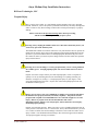
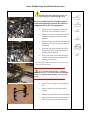
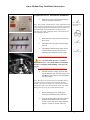
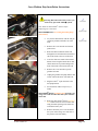
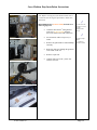
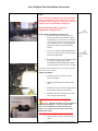
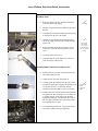
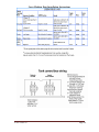
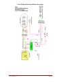
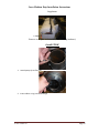
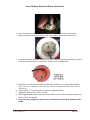
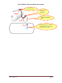
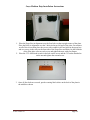
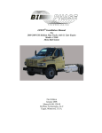
Isuzu Medium Duty Installation Instructions LPEFI Installation Manual For 2012 Isuzu Medium Duty Trucks with 6.0 Liter Engine Models: W5500 Mono-Rail System 274571 REV. A Revised Feb 22, 2012 First Edition September 2008 Manual # M4-xxx-xx Bi-Phase Technologies, LLC Eagan, Minnesota, U.S.A. Isuzu Medium Duty Installation Instructions REVISION HISTORY REV A DESCRIPTION CREATE PART NUMBER 274571 REV. A DATE EWO D.F.T.G 5-20-13 48887 P.C.W Page 2 Isuzu Medium Duty Installation Instructions Bi-Phase Technologies, LLC Introduction This instruction booklet shows how to convert a gasoline vehicle to run on clean burning propane utilizing our LPEFI (Liquid Propane Electronic Fuel Injection) system. The system is vehicle specific and installing a system on any vehicle that the kit was not designed for will void the warranty and may also violate emission laws. Anyone who installs or repairs the LPEFI system must be trained and certified. This must also include training in the safe handling and characteristics of propane. Bi-Phase Technologies provides such training upon request. Some states may require a license to work on propane vehicles. Consult your state or local authorities or your state propane gas association. Bi-Phase Technologies, LLC is not responsible for your oversight to comply with federal, state or local laws regulating the installation or repair of propane gas systems. The LPEFI system is a sequential multi-port fuel injection system that injects propane in a liquid state to the engine. It works much the same way as a modern sequential multi-port gasoline fuel injection system and can be diagnosed with the same diagnostic scanners used for gasoline vehicles. The LPEFI system is covered by U.S. and International patents. The LPEFI system is also certified to the United States E.P.A. standards. The information in this manual is believed to be accurate as of its date of publication, but it is subject to change. Up-to-date information and changes, if any, can be requested from Bi-Phase Technologies. In the event of any safety-related changes Bi-Phase Technologies will notify all customers who returned the warranty registration card for the affected vehicles. For more information contact: Bi-Phase Technologies, LLC 2945 Lone Oak Drive, Suite 150 Eagan, MN 55121 (651) 681-4450 Tech. Support line (888) 465-0571 274571 REV. A Page 3 Isuzu Medium Duty Installation Instructions Bi-Phase Technologies, LLC Table of Contents Introduction………………………………………….. Notes……………………………………………….... Propane Safety……………………………………….. Facts about Propane & Propane Powered Vehicles…. Approximate Properties of LP Gases………………... Pre-Installation Inspection…………………………... 2 5 6 8 9 10 Instructions Remove gasoline system LPEFI System Prepare LPEFI fuel rails Install LPEFI system Fuel rails Spark Plugs Main wire harness Gauge Tank Primary & loop hose Completing Wire Harness Installation…………..… Installing Labels…….……………………..…….… Testing the Installation…………………….…….… Purge Logic…………………….………………..… Tank Control Box Wiring…………………………. Electrical wiring diagram…………………………. Post-Installation Inspection………………………... 274571 REV. A 11 12 12 13 14 16 17 18 20 20 22 24 24 25 26 Page 4 Isuzu Medium Duty Installation Instructions Bi-Phase Technologies, LLC Notes 274571 REV. A Page 5 Isuzu Medium Duty Installation Instructions Bi-Phase Technologies, LLC Propane Safety This is a safety alert symbol. It is used through out this manual to alert you to potential hazards. Whenever you see this symbol, you should read and obey the safety warnings that follow. Failure to obey these warnings could result in serious personal injury or property damage. Please read some of the Specific Warnings below before proceeding with the installation or repair of any propane system Warning: Always unplug the LPEFI control box or disconnect the battery before you work on any part of the LPEFI system. The LPEFI tank contains an electronic control box. Any time the driver door is opened, the LPEFI system could go into a purge mode, pumping liquid propane through the hoses and injectors. To prevent a sudden release of cold liquid propane, disconnect the power from the control box before you loosen any hose fittings. Failure to do this could cause personal injury and fire hazard. Warning: Never loosen fittings or vent any propane unless you are wearing insulated PVC rubber gloves. Escaping liquid propane can cause frostbite and severe freeze burns. Propane is stored as a liquid. When you release liquid propane, it tries to evaporate as quickly as it can, by absorbing heat from its surroundings. Everything it touches gets chilled to –44 degrees F (-42 deg. C). If liquid propane sprays on your fingers, it will freeze them-right down to the bone. Anyone who works with liquid propane must wear insulated PVC rubber gloves. Danger: Do not remove any valves, bulkheads or fittings from a propane tank unless the tank has been properly drained (evacuated) completely. The pressure inside a propane tank can push a loosened bulkhead or valve out with enough force to cause injury. Release of propane in an uncontrolled situation will create a flammable/explosive mixture of air and propane, which could cause serious injury, death and property damage. Propane is stored under pressure. When you remove a valve or bulkhead from the tank, all of the pressure is released at once, in a violent rush. Always drain the tank before you work on it. Failure to do this will result in damage to the tank or valves and can result in severe injury or death. You should drain the tank using a flare stack in an approved safe manner. Your propane supplier can help you with this. 274571 REV. A Page 6 Isuzu Medium Duty Installation Instructions Bi-Phase Technologies, LLC Danger: Do not vent or release propane indoors or near sewers, pits or low lying areas. Propane can accumulate in low spots, creating a fire hazard. Propane can also displace oxygen, creating a suffocation hazard. Propane is heavier than air. It can fill low, sheltered areas with flammable vapors. If these vapors are ignited, they can create a fire or explosion, causing severe property damage, injury or death. Never release propane near sewers, pits or indoors. Warning: Keep all sources of ignition away from propane vehicles while the fuel system is being serviced. Even if the tank and fuel lines are empty, there may still be flammable vapors near the vehicle. Do not allow smoking, sparks, flames, running vehicles or other sources of ignition near the vented propane. Failure to do this could result in fire or explosion, causing severe property damage, injury or death. Warning: Do not disconnect any propane hoses unless they have been properly drained completely. Propane in the hoses is kept under pressure, even when the engine is off. When you disconnect a hose, the internal pressure is released all at once. Always drain the fuel lines before you disconnect them. Failure to do this can result in damage to the hose fitting and possible injury. WARNING: 274571 REV. A NO SMOKING OR OPEN FLAMES IN OR AROUND PROPANE VEHICLES DURING FUELING OR SERVICING. Page 7 Isuzu Medium Duty Installation Instructions Bi-Phase Technologies, LLC Facts about Propane & Propane Powered Vehicles Propane gas is the most widely used alternative fuel, with nearly 4 million vehicles worldwide running on propane. More than 350,000 vehicles run on propane in the U.S., according to the U.S. Department of Energy’s Alternative Fuels Data Center. Propane powered vehicles offer the best combination of durability, performance and driving range. The first propane powered vehicle ran in 1913. Bi-Phase Technologies’ LPEFI (Liquid Propane Electronic Fuel Injection) system has surpassed other technologies today by introducing liquid fuel injection. This technology improves power, efficiency and operating characteristics. For more information call for our General Information and Training Manual. Safety comes first is a motto you should always live by. Without knowledge of a product it is hard to follow this motto. In our manuals we try to stress the need for knowledge and provide warning signs to alert you. It is your responsibility to know the law. NFPA, National Fire Protection Association, has manuals to help you understand safe handling of many products. We recommend that you obtain and read their NFPA #58, Standard for the Storage and Handling of Liquefied Petroleum Gases. To further enhance the industry’s safety and service, a number of training programs and efforts have been implemented throughout the country. The National Propane Gas Association has developed a Certified Employee Training Program (CETP), which provides service personnel with a complete technical training curriculum. We encourage you to contact your state propane gas association or the National Propane Gas Association for more information on how you can benefit from such programs. Visit www.propanesafety.com for more information. 274571 REV. A Page 8 Isuzu Medium Duty Installation Instructions Bi-Phase Technologies, LLC Approximate Properties of LP Gases (Commercial Propane) Specific gravity of liquid (water = 1) at 60 degrees F. 0.504 Initial boiling point at 14.7 psia, degrees F. - 44.0 Weight in lbs per gallon of liquid at 60 degrees F 4.24 Specific heat of liquid, BTU/lb. at 60 degrees F. 0.630 Cubic ft. of vapor per gallon at 60 degrees F. 36.38 Cubic ft. of vapor per pound at 60 degrees F. 8.66 Specific gravity of vapor (air = 1) at 60 degrees F. 1.50 Ignition temperature in air, degrees F. 920 to 1120 Maximum flame temperature in air, degrees F. 3,595 Limits of flammability in air Percent of vapor in air/gas mixture a) Lower b) Upper 2.15 9.60 Heating values a) BTU per cubic foot b) BTU per pound c) BTU per gallon 2,488 21,548 91,500 Chemical formula C3H8 Vapor pressure in psig a) 70 degrees F b) 100 degrees F c) 105 degrees F 127 196 210 274571 REV. A Page 9 Isuzu Medium Duty Installation Instructions Bi-Phase Technologies, LLC Pre-Installation Inspection (Recommended) If your vehicle is equipped with a single gasoline fuel tank, and you will be installing a single propane fuel tank follow the procedure in this manual. If the vehicle is new and has less than 1,500 miles we recommend the following: Visually inspect the vehicle Is the malfunction indicator lamp illuminated? Does the engine start and run smooth? Are there any fluid leaks? Install a diagnostic scan tool and verify there are no DTCs (Diagnostic Trouble Codes) stored in the computer memory If the vehicle is used and has more than 10,000 miles we recommend in addition to the above: Note: Remove and examine the spark plugs and conduct a compression test During diagnostic scan mode document the following from the scan tool data stream: Short term fuel trim, bank 1 & 2 Long term fuel trim, bank 1 & 2 IAC (idle air control %) Oxygen sensor activity Proceed with the LPEFI system installation if all conditions are acceptable. If any problems are discovered it is not recommended to install the LPEFI system until the problems are repaired. After the installation is complete refer to the Post-Installation Inspection found in this manual. 274571 REV. A Page 10 Isuzu Medium Duty Installation Instructions Warning: Disconnect the battery before you work on any part of the LPEFI system. Remove gasoline fuel rails, fuel line, tank & evaporative emission system (if the vehicle is equipped with the EVAP components): Unplug injector wiring harness from each injector for use on the LPEFI injectors Remove four (6 mm) mounting studs and nuts holding the gasoline fuel rails to the intake manifold Remove the plate from the top of the intake and pull the two wire harness’s up so the rails can be removed Place drain pan under passenger side of bell housing to catch any gasoline spilled while disconnecting the fuel lines Using a 3/8” QD tool, disconnect the supply fuel lines from the steel line attached to the passenger side frame rail Note: Gasoline residue could drain out of the lines and rails when you disconnect. __________________________________________ Caution: Gasoline under pressure. Gasoline is flammable & toxic. Use extreme caution and eliminate all sources of ignition while handling. Wear gloves & goggles. __________________________________________ Remove the EVAP purge valve from the fuel rail Install a vacuum cap to the canister purge solenoid Remove the gasoline fuel rails from the engine Drain all gasoline from the fuel tank, lines and discard in the proper environmental manner -10 - 8 mm socket & ¼” drive ratchet 10 mm socket & ¼” drive ratchet Drain pan 3/8” QD tool Pliers Isuzu Medium Duty Installation Instructions Prepare the LPEFI fuel rails for installation: Remove the new fuel rails from the package; retain the envelope with the rails Note: The envelope contains decals, owner information card and a warranty registration card. The warranty registration card, along with the Post-Installation Inspection form, must be filled in and returned to Bi-Phase Technologies for warranty to be valid. Label placement is described later in this installation manual. Place both rails on the bench as shown in the photo at left The bottom rail in the photo is the passenger side rail The bushings and hold down clamps are not mounted on the rails and will need to be installed prior to installation on the engine 15/16” socket & ratchet with same size wrench 3/8” QD tool Clean motor oil ________________________________________ Caution: Gasoline under pressure. Gasoline is flammable & toxic. Use extreme caution and eliminate all sources of ignition while handling. Wear gloves & goggles. ________________________________________ Lubricate the lower o-rings (green) on each injector and place each rail on the engine with the QD hose inlet connector facing toward the rear of the engine Note: The injector electrical connectors should be facing outward to allow clearance between injector & intake plenum. The electrical connector could interfere with the installation of the rail or the installation of the rail could damage the injector if not pre-positioned outward. 274571 REV. A Before installing fuel rail, install spacer between the manifold and the rail bracket Using the original 6 mm bolts taken from the gasoline rail mounting bracket secure the LPEFI injector rails to the intake manifold; tighten to a torque of 12 NM (106 in-lb) Page 12 Isuzu Medium Duty Installation Instructions Install original gasoline injector wiring harness and connect each injector connector to the proper cylinder Remove and discard the bracket on the rear of the driver side head Note: When disconnecting or connecting injector connectors be careful and pull locking tab up to disconnect and push in on connector (squeeze) to disconnect. After reconnecting push locking tab down to lock connector. Be careful not to break this plastic tab and locking piece. New Spark Plugs: Replace the spark plugs with NGK-IFR7F-8DS (stock #5794) 14mm x 5/8" Hex Iridium Platinum resister plugs. Plug gap: .8mm or 0.31 Drain pan Installation Manual, GM Medium Duty Trucks, 2005 274571 REV. A Page 13 Isuzu Medium Duty Installation Instructions Main wire harness: Warning: Disconnect the battery before you work on any part of the LPEFI system. 7/8” wrench Note: Route the main LPEFI harness before completing any connections. Main LPEFI harness (to existing Isuzu fuel pump wire harness) Lay out the main harness with the four pin connector pointed toward the rear of the truck Remove the cover from the wire harness junction box Route the harness under the frame and through the box and down the inside driver side of the frame to the rear of the truck Leave the white wire trunk of the LPEFI harness loose along the outside driver side chassis frame rail to permit routing to the front of the truck to the inside of the cab Remove the cover from the top of the gasoline fuel tank. Unplug the gasoline fuel pump harness and reroute it down the driver side frame rail Plug the LPEFI 4 pin connector to the fuel pump harness Secure harness with tie wraps every 8 inches Nylon tie straps Nylon tie straps Main LPEFI harness (to battery box) branch, is an orange wire with an in-line fuse and eyelet connector on the end 274571 REV. A Route the main LPEFI harness (to battery box) branch across the cross member then along the inside passenger side frame rail towards the battery box Remove the battery box cover and install the eyelet on the orange wire with fuse to the positive side of the battery Page 14 Isuzu Medium Duty Installation Instructions Note: Before securing any of the harness makes sure it is routed to meet the length requirement to make each connection Main LPEFI harness (to door switch) branch, it is a white 16-gauge wire 274571 REV. A Guide the main LPEFI wiring harness white wire (to door switch) along the driver side frame to the front of the truck Secure harness with tie wraps every 8 inches Remove the grill and driver side headlamp assembly Route the white wire through the grommet to the inside of the cab Remove carpet trim Connect white wire to the yellow wire with the red tracer 10 mm & 13 mm socket & ¼” drive ratchet phillips screw driver Nylon tie straps Pliers ½” wrench or socket & ratchet Page 15 Isuzu Medium Duty Installation Instructions Install LPEFI system Gauge: Warning: Disconnect the battery before you work on any part of the LPEFI system. Phillips screwdriver Wire connector tool or equivalent Magnet Install fuel level sending unit on the primary tank Note: Use the 40-250 ohm resistance fuel level gauge sending unit supplied in the kit. When installing a fuel level gauge sending unit always reset the sender to zero using a small magnet; after installed on the tank the sending unit’s needle should register zero or empty unless there is fuel in the tank Main LPEFI harness (to sending unit) branch, it is a black two pin connector Connect the main LPEFI harness (to sending unit) branch to the fuel level gauge; use nylon wire ties to secure the primary hose 9/16” wrench or socket & ratchet Note: Always be aware of routing. Do not route near the exhaust and always use split loom to prevent chaffing. Prepare to install the LPEFI protecting cover with the 3/8” bolts provided; at this time leave the bolts loose and do not connect the main LPEFI harness (to purge box, relay and LPDM, to the electronic control box and relay Installation Manual, GM Medium Duty Trucks, 2006 274571 REV. A Page 16 Isuzu Medium Duty Installation Instructions Tank: Note: Verify tank is holding pressure before installing. Tanks are ship under pressure with argon. To verify, open spitter valve, if argon gas escapes, close valve and continue, if not contact Bi-Phase Technologies. Before mounting tank to frame see supplement on pages 26-30 Primary tank is installed on the driver side Measure the tank to mark the holes to be drilled in the frame; the front tank support mounting holes are located 14 1/8” from the “Front of body must not extend beyond this line” Warning; measure rear mounting hole appropriate with the rear tank mounting bracket Use an 5/8” drill bit to drill mounting holes; use the 5/8” bolts, washers & nuts provided in the kit to mount tank Raise the tank into place and install the bolts, two bolts per support; tighten all the mounting bolts until the Belleville washers are flat or torque to about 52 ft-lb or 70 Nm 11/16 drill bit and drill 15/16” wrench, socket & ratchet or impact Note: Due to the OEM placement of the exhaust system a tank heat shield is required. Fill hose installation Install the fill hose assembly exactly as shown in the photo. Attach the fill fitting to the bracket on the tank. Install the 90 degree from the longest hose to the fill fitting. (Torque to 44-48 ft-lb.) Install the other end of the hose to the 80% valve (Torque to 44-48 ft-lb.) ________________________________________ Warning: Stop fill valve elbows are never tightened at the tank manufacturer. The valve is tight but the elbow must be tightened and clocked to the proper position. Do not allow the valve itself to move while tightening the elbow. ___________________________________________ 274571 REV. A Attach fill filter to frame rail will clamp as shown. Verify the hose is routed in a way that there is no interference with chassis components that could cause chaffing Page 17 Isuzu Medium Duty Installation Instructions Primary hose: Route the primary fuel line with flare end fitting toward the front of the engine The hose will route from the LPDM over the top of the tank Turn the hose toward the transmission bell housing, it will run over the rear of the engine Continue to route the hose around the passenger side of the engine and loop back towards the right injector rail Before lowering cab modify the engine cover by removing 8” out of the lower right corner of the cover Cut at the bottom of lower rib After lowering cab verify engine cover does not touch the loop or primary hose. 1 ¼” wrench 7/8” wrench 3/4” wrench 7/16” wrench, socket & ratchet 10” or 12” crescent wrench Attach primary fuel hose to injector rail 274571 REV. A Pull out about 2-1/2 inches of the white inner hose out of the primary fuel line Lubricate inner line with clean motor oil Carefully guide the inner line into the center of the rail and feel for the line to engage the internal o-ring (see picture on left); 2” of inner line must be inserted into the rail to make a proper connection Pull the outer hose onto the fitting on the end of the rail, tighten the flare nut (torque to 33-38 ft-lb); use a “backup wrench” on the rail to keep the brass fitting from turning as you tighten the flare nut; do not over tighten the flare nut; (brass fitting on the rail is tightened to 5-6 ft-lb) After tightening the flare nut, verify the hose does not come in contact with any components 7/8” open end wrench 1” open end wrench Page 18 Isuzu Medium Duty Installation Instructions Install LPEFI System Attach the primary line to the LPDM Position the primary hose to be connected to the LPDM by routing the hose over the tank Remove retaining screws, plate, gasket and split collar retainers from LPDM Install plate and gasket onto hose end fitting of primary hose Lubricate hose end fitting metal surface and white nylon inner line Insert into center of LPDM port and push in slowly until metal hose end fitting is touching the top of the brass bushing in the port T-20 Torx driver Clean motor oil Clean motor oil Secure the Primary Hose Primary hose loop will determine how much slack is available to secure the primary hose; verify the primary hose is routed in a way that there is no interference with chassis components that could cause chaffing Insure that the hose is aligned so that no tension will be created on the fuel rail or the hold down clamps Install 3 P clamps on top of the tank shown Connect the hose to the fuel line bracket with a large P clamp. Refernce photo on page 19 Rear Primary Hose Bracket: Attach as shown with the supplied hardware Installation Manual, GM Medium Duty Trucks, 2005 Torque bracket to 24 ft lbs Front Primary Hose Bracket: 274571 REV. A Attach as shown with the supplied hardware Torque bracket to 24 ft lbs Page 19 Isuzu Medium Duty Installation Instructions Attach the loop hose to the injector rails Start with the 80-degree hose end on the crossover hose, lubricate the white nylon inner line and insert into injector rail on the driver side Lubricate white nylon inner line on the 45degree hose end and insert into the injector rail VERY IMPORTANT: Take extreme care to center the nylon line into the rail end fitting and slowly push the line all the way in (turn the hose from side to side or twist it as you are pushing it in). Once the white inner line is completely in, push the entire fitting into the rail until it clicks and locks Secure the loop hose Connect the loop hose to the fuel line bracket Verify the hose is routed in a way that there is no interference with chassis components that could cause chaffing Look at the QD fitting and verify the four locking tabs are secured on the hose fitting Install the P clamp on bracket as shown Completing Wire Harness Installation: 13 mm wrench or Ratchet & socket ½” wrench, Ratchet & socket ½” wrench, Ratchet & socket Primary tank Main LPEFI harness (to purge box, relay and LPDM) branch, is 4 connectors on 4 branches, tied together. Refer to page 31 274571 REV. A Using the cover plate previously remove, attach control and relay to plate with hardware provided. Secure to plate with 5/32 hex and 3/8 socket Connect main LPEFI harness connection to electronic purge box and relay and LPDM Assemble cover plate to rear of the primary tank 7/16” wrench, Ratchet & socket Secure hardware to cover plate and tank Page 20 Isuzu Medium Duty Installation Instructions Install labels on the truck/registration: Note: For best results when applying labels, dip the label in soapy water before you apply it to the truck. Slide the label into position, and then use a rubber squeegee to force out the air and water. 274571 REV. A Install PCM Label above OBD connector on dash panel (see photo 1) Install the EPA emissions label on rear of cab, in engine compartment. (see photo 2) Install the warning label on the driver’s side rear corner of the cab (see photo 3) If the truck does not have a box or body installed yet, put the propane diamond in the glove box for later placement (see photo 4) After the body is installed on the truck, install the “PROPANE” diamond on the back panel of the truck, toward the bottom right corner; do not install on the bumper. Place laminated owners information cab card in the glove box with the OEM’s owners manual & other GM information (see photo 5) Place 4 tie wire labels at both ends of the loop hose and primary hose (see photo 6) Place LPEFI label on each side of the cab corner panel (see photo 7) Fill out vehicle Post-Installation Inspection Form and return to Bi-Phase Technologies Rubber squeegee Page 21 Isuzu Medium Duty Installation Instructions Testing the Installation 1. Visually inspect the tank(s), the hoses, the wiring and the engine compartment. Is everything assembled properly? 2. Fill the tank with 20 to 30 gallons of propane. It is recommended that you purge the tank with propane vapor and check all the fittings on the tank for leaks before filling the tank completely. Use an approved leak detection fluid or an electronic leak detector to verify there are no leaks. If any leaks are found stop and repair the leaks. The battery should not be connected at this time. (If the tank was filled before installation it should have been checked for leaks at that time.) 3. Connect a fuel pressure test gauge to the Shrader valve on the LPDM 4. Fuel pressure should be 0 psi at first. 5. If the connections on the electronic purge control assembly have not been made connect at this time. 6. Connect the battery. You may hear a click at the tank. 7. Open the driver door to start a purge cycle. You should hear the solenoid valves click and the pump running inside the tank. If not, check the electrical connections and refer to the troubleshooting section in the service manual. 8. Simultaneously with the preceding step you should inspect all hose connections, the LPDM, the fuel rail connections and the injectors for leaks. If any leaks are found you should disconnect the electronic purge control assembly, evacuate the lines and repair. See the service manual for procedures. 9. When the purge cycle ends, listen for leaking fuel near the hoses and around the entire system. If you do not hear any obvious hissing or smell propane, turn on the ignition key but do not start. This will start the fuel pump, followed by a purge cycle. 10. When you hear the fuel pump stop running notice the fuel pressure on the test gauge. This pressure should be anywhere from 30 psi in cold weather to 180 psi in hot weather. 11. Turn the key off, then on again to start another purge cycle. 12. While the pump is running, observe the fuel pressure. It should be 35 to 55 psi higher than it was in step 11. 13. Turn the key off and check for leaks at every hose fitting on the vehicle. Apply an approved leak detection fluid (similar to soapy water) or use an electronic propane leak detector. The tank, tank valves, fuel injectors and fuel rails have been tested at the factory but you must recheck, and check the hoses and hose fittings. On dual tank trucks check all of the hoses between the tanks, too. 274571 REV. A Page 22 Isuzu Medium Duty Installation Instructions Testing the Installation (cont’d) 14. If there are no leaks, start the engine. 15. Connect a diagnostic scan tool to the vehicle. (The connector is usually under the bottom of the dash.) 16. With the engine running, check the diagnostic trouble codes (DTCs). Correct any problems you find. If the engine is not running smoothly, refer to the LPEFI service manual. 17. If there are no codes and the engine is running smoothly let the vehicle run until it is to full operating temperature (190° F on your Scan tool). 18. Turn the key off and follow the testing procedures described in the Post-Installation Inspection 19. Fill out the Post-Installation Inspection completely. 20. Turn off the engine and disconnect the fuel pressure gauge set. Be sure to reinstall the dust cap on the Shrader valve. 21. Drive the vehicle for at least 15 minutes, if possible. Drive under various conditions and a variety of speeds. 22. After the drive notice the long-term fuel trims as noted in the post-inspection. The long-term fuel trims should not be the same as they were before the drive. The long-term fuel trims should not be more than + or – 20%. 23. After driving and inspecting the vehicle turn it off and let it sit with the hood and doors closed for 15 minutes. After 15 minutes return to the vehicle, open the door to initiate a purge and start the engine. If the engine starts easily, 3 seconds or so, the vehicle is ready to use. 24. If there are no leaks, no DTCs and the engine runs well (smooth idle, smooth acceleration, good power), the vehicle is ready to use. 25. If you did not fill out the warranty registration card in the Installing Labels Procedure do so now. Also complete the Post-Installation Inspection and return both to Bi-Phase Technologies to establish the warranty start date for your vehicle. 274571 REV. A Page 23 Isuzu Medium Duty Installation Instructions 274571 REV. A Page 24 Isuzu Medium Duty Installation Instructions 274571 REV. A Page 25 Isuzu Medium Duty Installation Instructions 274571 REV. A Page 26 Isuzu Medium Duty Installation Instructions Supplement Remove cover plate and set aside (save mounting hardware) Install LPDM 1. Attach pump clip to filter cup 2. Insert rubber o-ring into LPDM flange 274571 REV. A Page 27 Isuzu Medium Duty Installation Instructions 3. Insert the pump from the LPDM into filter cup. Position the pump in cup so the clip goes between the hose and the wires on the pump. Attach the spring to other side of the cup 4. Proceed to mounting and tighten LPDM to tank flange. Make sure all hoses and wiring is pushed inside the tank with no kinks or sharp bends. LPDM is clock at 11:00 position. 5. Install the new aluminized coated bolts that came with the new o-ring and hand tighten (note: anti-seize compound is not necessary with these aluminized coated bolts, but not prohibited) 6. A deep well 3/8” 12-point socket is required to tighten the bolts 7. Tighten the bolts evenly, a little at a time 8. Finish tightening the bolts in the order shown below, or in a crisscross pattern; torque the bolts to 20-25 foot pounds 9. Purge the tank, purging the tank can be performed after the tank is mounted to the frame 274571 REV. A Page 28 Isuzu Medium Duty Installation Instructions Purge the Tank ______________________________________________________________________________ _______ Warning: Purge the tank outdoors in the open, away from buildings, other vehicles, electrical devices, gas appliances, and other sources of ignition. Disconnect the electrical connection from the tank control box and disconnect the battery to avoid ignition inside the tank. Any spark or flame can ignite a cloud of propane vapor in or near the tank which could cause severe burns, personal injury and/or property damage. Always disconnect the negative battery terminal first. ______________________________________________________________________________ _______ Purging the tank is different from the purge cycle in the LPEFI system. Purging the tank means removing the air (oxygen) and moisture from inside the tank before putting the tank into service. This is a required procedure on all new tanks (tanks that have never been filled with propane) or tanks that have been evacuated and opened to the atmosphere for service or for any reason. Note: Purging the tank is always required if the tank is evacuated and any valve or component is removed that causes the tank to be exposed to the atmosphere. Why Purge a Tank? Most tanks are steel and are prone to rust. To prevent rust, purging will remove air (oxygen) and moisture which causes rust. Also, by purging and removing the air (oxygen) from the tank there is no chance of air in the tank causing pressure fluctuations. This trapped air could also cause excess pressure in the tank and could cause a slow fill situation. New tanks come purged with an inert gas and this same situation could also occur if the inert gas is not purged from the tank. Always follow proper purge procedures. The LPEFI system uses an electric fuel pump mounted inside the tank. Propane must be mixed with air between 2.15% and 9.6% fuel to air mixture to be combustible or flammable. If not purged, a spark from the electric fuel pump could ignite such a mixture. Fortunately, this combustible mixture is seldom found inside a tank and by purging the tank prior to filling or refilling, the tank will prevent the air/fuel mixture from ever reaching a combustible mixture. How to Purge a Tank Warning: You purge the tank in the open (outside), at least 25 feet from any building. You can perform the purge with the tank installed on the vehicle. You should not connect any electrical connectors to the tank after service or before filling a new tank. If the tank is connected electrically, DISCONNECT it from the tank control box and disconnect the vehicle battery (always disconnect the negative terminal first). It is also recommended that the tank be grounded to earth ground with a cable (like a battery jumper cable) to prevent sparks due to static electricity. 274571 REV. A Page 29 Isuzu Medium Duty Installation Instructions At this point all replaced components should be installed and tightened to specification. The following procedures or method is approved by the United States National Propane Gas Association (NPGA). For more information you can go to their website at www.npga.org. 1. Remove the brass cap from the vapor or spitter service valve on the tank you want to purge – the tank should not have fuel at this time (it should be totally evacuated); some pressure may build up if the tank was closed up for a period of time due to the porosity of the steel; release this pressure build up before starting the purging process 2. Open the valve to release such pressure build up and allow it to equalize to atmospheric pressure 3. Connect the propane vapor source to the fill connection on the tank or if the tank is equipped with a vapor service valve, hook up to the vapor service valve 4. The propane vapor used can be a small cylinder, such as a barbeque grill cylinder – these cylinders are vapor service only; attach an adjustable high pressure regulator to the cylinder and adjust the outlet pressure of the regulator to 15 p.s.i. (this is to be connected to vapor service only) 5. Slowly open the vapor service valve on the cylinder and allow vapor pressure to equalize into the tank being purged to15 p.s.i. and turn off the valves 6. Release all the pressure in the tank being purged to atmosphere or to a flare stack and close the valve when all the vapor pressure is released 7. In order to ensure that at least 95% of the air is removed, the container must be pressurized and bled down or depressurized several times – usually 3 to 5 times is sufficient 8. The closer to the top of the tank the valve you are using to release the pressure or depressurize the tank, the better Note: If there is any indication of moisture or water in the tank and most of the liquid water was removed during service of the tank, there remains some moisture. In this case, it is a good idea to inject some methanol into the tank before filling the tank with fuel. On average, one pint of methanol per 100 gallons of propane or 1 gallon of methanol per 1,000 gallons or propane will resolve any moisture or water residue. 9. On the last purge with vapor, leave the tank being purged pressurized and this is a good time to check the tank and valves for leaks; check for leaks with an approved leak detection fluid or electronic combustible gas detector 10. If no leaks are found and the purge process is complete, the tank is ready to be filled with propane liquid 11. Fill the tank with 5 gallons of fuel before any electrical components are reconnected. This will insure there is no or very little air in the tank. 274571 REV. A Page 30 Isuzu Medium Duty Installation Instructions Connecting to a service valve is also allowable Install high pressure regulator 0 to 30 p.s.i. here and adjust to 15 p.s.i. Small vapor service propane cylinder, like a barbeque grill cylinder Release purging pressure to atmosphere in a safe manner from a service valve located close to the top of the tank, repeat purging procedure 3 to 5 times 274571 REV. A Page 31 Isuzu Medium Duty Installation Instructions 1. Place the Purge Box in alignment over the four holes on the top right corner of the plate. Place the Relay in alignment over the 2 holes in the top left area of the plate. Put washers on all of the screws then place the screws with washers in all four holes in the purge box and two screws in the relay on the front side of the Purge Box and Relay On the backside of the Plate place a nut on each screw and tighten the nuts with your fingers 2. Place the 5/32 Allen head wrench in the hole on the screw and the 3/8 socket attached to on the nut and tighten the nut and screw 3. Once all four bolts are secured, put the warning label sticker on the back of the plate in the middle as shown 274571 REV. A Page 32