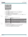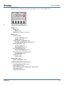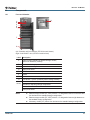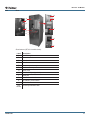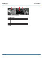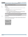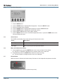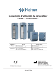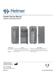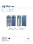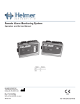
1
Freezer Operation Manual i.Series® and Horizon Series™ Model Group Plasma Storage Laboratory i.Series Horizon Series iPF120-4, iPF120-8, iPF125-4, iPF125-8 HPF120-4, HPF120-8, HPF125-4, HPF125-8 iHPF120-4, iHPF120-8, iHPF125-4, iHPF125-8 HHPF120-4, HHPF120-8, HHPF125-4, HHPF125-8 iLF120, iLF125 HLF120, HLF125 HELMER SCIENTIFIC 14400 Bergen Boulevard Noblesville, IN 46060 USA PH +1.317.773.9073 FAX +1.317.773.9082 USA and Canada 800.743.5637 360086-1/M 0086 ISO 13485:2003 CERTIFIED Document History Revision M Date CO 02 MAY 2014* 9415 Supersession Revision Description M supersedes A, B, C, D, E, F, G, H, I, J, K, L Revised layout for ease of navigation and locating information. * Date submitted for Change Order review. Actual release date may vary. 360086-1/M i Contents Section I: General Information. . . . . . . . . . . . . . . . . . . . . . . . . . . . . . . . . . . . . . . . . 4 1 About this Manual . . . . . . . . . . . . . . . . . . . . . . . . . . . . . . . . . . . . . . . . . . . . . . . . . . . . . . . . . . . 4 1.1 1.2 1.3 Intended Audience. . . . . . . . . . . . . . . . . . . . . . . . . . . . . . . . . . . . . . . . . . . . . . . . . . . . . . . . . . . . . . . . . . . . . . 4 Model References. . . . . . . . . . . . . . . . . . . . . . . . . . . . . . . . . . . . . . . . . . . . . . . . . . . . . . . . . . . . . . . . . . . . . . 4 Copyright and Trademark. . . . . . . . . . . . . . . . . . . . . . . . . . . . . . . . . . . . . . . . . . . . . . . . . . . . . . . . . . . . . . . . 4 2Safety . . . . . . . . . . . . . . . . . . . . . . . . . . . . . . . . . . . . . . . . . . . . . . . . . . . . . . . . . . . . . . . . . . . . . 4 2.1 2.2 2.3 Safety Definitions . . . . . . . . . . . . . . . . . . . . . . . . . . . . . . . . . . . . . . . . . . . . . . . . . . . . . . . . . . . . . . . . . . . . . . 4 Product Labels . . . . . . . . . . . . . . . . . . . . . . . . . . . . . . . . . . . . . . . . . . . . . . . . . . . . . . . . . . . . . . . . . . . . . . . . 5 Avoiding Injury. . . . . . . . . . . . . . . . . . . . . . . . . . . . . . . . . . . . . . . . . . . . . . . . . . . . . . . . . . . . . . . . . . . . . . . . . 5 3 General Recommendations. . . . . . . . . . . . . . . . . . . . . . . . . . . . . . . . . . . . . . . . . . . . . . . . . . . 5 3.1 3.2 3.3 Intended Use. . . . . . . . . . . . . . . . . . . . . . . . . . . . . . . . . . . . . . . . . . . . . . . . . . . . . . . . . . . . . . . . . . . . . . . . . . 5 General Use . . . . . . . . . . . . . . . . . . . . . . . . . . . . . . . . . . . . . . . . . . . . . . . . . . . . . . . . . . . . . . . . . . . . . . . . . . 5 Initial Loading . . . . . . . . . . . . . . . . . . . . . . . . . . . . . . . . . . . . . . . . . . . . . . . . . . . . . . . . . . . . . . . . . . . . . . . . . 5 4 Specifications. . . . . . . . . . . . . . . . . . . . . . . . . . . . . . . . . . . . . . . . . . . . . . . . . . . . . . . . . . . . . . . 6 5Compliance. . . . . . . . . . . . . . . . . . . . . . . . . . . . . . . . . . . . . . . . . . . . . . . . . . . . . . . . . . . . . . . . . 7 5.1 5.2 Regulatory Compliance. . . . . . . . . . . . . . . . . . . . . . . . . . . . . . . . . . . . . . . . . . . . . . . . . . . . . . . . . . . . . . . . . . 7 WEEE Compliance. . . . . . . . . . . . . . . . . . . . . . . . . . . . . . . . . . . . . . . . . . . . . . . . . . . . . . . . . . . . . . . . . . . . . 7 6Installation . . . . . . . . . . . . . . . . . . . . . . . . . . . . . . . . . . . . . . . . . . . . . . . . . . . . . . . . . . . . . . . . . 8 6.1 Location Requirements. . . . . . . . . . . . . . . . . . . . . . . . . . . . . . . . . . . . . . . . . . . . . . . . . . . . . . . . . . . . . . . . . . 8 6.2Placement. . . . . . . . . . . . . . . . . . . . . . . . . . . . . . . . . . . . . . . . . . . . . . . . . . . . . . . . . . . . . . . . . . . . . . . . . . . . 8 6.3 Temperature Probes. . . . . . . . . . . . . . . . . . . . . . . . . . . . . . . . . . . . . . . . . . . . . . . . . . . . . . . . . . . . . . . . . . . . 8 6.4 Chart Recorder. . . . . . . . . . . . . . . . . . . . . . . . . . . . . . . . . . . . . . . . . . . . . . . . . . . . . . . . . . . . . . . . . . . . . . . . 9 6.4.1 Install and Change Chart Paper. . . . . . . . . . . . . . . . . . . . . . . . . . . . . . . . . . . . . . . . . . . . . . . . . . . . . 9 7 Maintenance Schedule . . . . . . . . . . . . . . . . . . . . . . . . . . . . . . . . . . . . . . . . . . . . . . . . . . . . . . 10 Section II: i.Series® - All Models. . . . . . . . . . . . . . . . . . . . . . . . . . . . . . . . . . . . . . . 11 8Operation . . . . . . . . . . . . . . . . . . . . . . . . . . . . . . . . . . . . . . . . . . . . . . . . . . . . . . . . . . . . . . . . . 11 8.1 8.2 8.3 8.4 8.5 8.6 8.7 Initial Start Up. . . . . . . . . . . . . . . . . . . . . . . . . . . . . . . . . . . . . . . . . . . . . . . . . . . . . . . . . . . . . . . . . . . . . . . . . 11 Normal Operation . . . . . . . . . . . . . . . . . . . . . . . . . . . . . . . . . . . . . . . . . . . . . . . . . . . . . . . . . . . . . . . . . . . . . . 11 Change Temperature Setpoint . . . . . . . . . . . . . . . . . . . . . . . . . . . . . . . . . . . . . . . . . . . . . . . . . . . . . . . . . . . 12 Set Alarm Parameters. . . . . . . . . . . . . . . . . . . . . . . . . . . . . . . . . . . . . . . . . . . . . . . . . . . . . . . . . . . . . . . . . . 13 Active Alarms. . . . . . . . . . . . . . . . . . . . . . . . . . . . . . . . . . . . . . . . . . . . . . . . . . . . . . . . . . . . . . . . . . . . . . . . . 13 Mute and Disable Active Alarms. . . . . . . . . . . . . . . . . . . . . . . . . . . . . . . . . . . . . . . . . . . . . . . . . . . . . . . . . . 13 Defrost Status. . . . . . . . . . . . . . . . . . . . . . . . . . . . . . . . . . . . . . . . . . . . . . . . . . . . . . . . . . . . . . . . . . . . . . . . 14 9 i.Center Screen Reference . . . . . . . . . . . . . . . . . . . . . . . . . . . . . . . . . . . . . . . . . . . . . . . . . . . 14 10Components. . . . . . . . . . . . . . . . . . . . . . . . . . . . . . . . . . . . . . . . . . . . . . . . . . . . . . . . . . . . . . . 16 10.1 Front and Chamber. . . . . . . . . . . . . . . . . . . . . . . . . . . . . . . . . . . . . . . . . . . . . . . . . . . . . . . . . . . . . . . . . . . . 16 10.2Rear. . . . . . . . . . . . . . . . . . . . . . . . . . . . . . . . . . . . . . . . . . . . . . . . . . . . . . . . . . . . . . . . . . . . . . . . . . . . . . . . 17 10.3Top. . . . . . . . . . . . . . . . . . . . . . . . . . . . . . . . . . . . . . . . . . . . . . . . . . . . . . . . . . . . . . . . . . . . . . . . . . . . . . . . . 18 360086-1/M ii Section III: Horizon Series™ - Plasma Storage Models. . . . . . . . . . . . . . . . . . . . 19 11Operation . . . . . . . . . . . . . . . . . . . . . . . . . . . . . . . . . . . . . . . . . . . . . . . . . . . . . . . . . . . . . . . . . 19 11.1 11.2 11.3 11.4 11.5 11.6 11.7 Initial Start Up. . . . . . . . . . . . . . . . . . . . . . . . . . . . . . . . . . . . . . . . . . . . . . . . . . . . . . . . . . . . . . . . . . . . . . . . 19 Normal Operation . . . . . . . . . . . . . . . . . . . . . . . . . . . . . . . . . . . . . . . . . . . . . . . . . . . . . . . . . . . . . . . . . . . . . 19 Change Temperature Setpoint . . . . . . . . . . . . . . . . . . . . . . . . . . . . . . . . . . . . . . . . . . . . . . . . . . . . . . . . . . . 20 Set Alarm Parameters. . . . . . . . . . . . . . . . . . . . . . . . . . . . . . . . . . . . . . . . . . . . . . . . . . . . . . . . . . . . . . . . . . 21 Active Alarms. . . . . . . . . . . . . . . . . . . . . . . . . . . . . . . . . . . . . . . . . . . . . . . . . . . . . . . . . . . . . . . . . . . . . . . . . 21 Mute and Disable Active Alarms. . . . . . . . . . . . . . . . . . . . . . . . . . . . . . . . . . . . . . . . . . . . . . . . . . . . . . . . . . 21 Defrost Status. . . . . . . . . . . . . . . . . . . . . . . . . . . . . . . . . . . . . . . . . . . . . . . . . . . . . . . . . . . . . . . . . . . . . . . . 21 12 Horizon Series Screen Reference. . . . . . . . . . . . . . . . . . . . . . . . . . . . . . . . . . . . . . . . . . . . . 22 13Components. . . . . . . . . . . . . . . . . . . . . . . . . . . . . . . . . . . . . . . . . . . . . . . . . . . . . . . . . . . . . . . 24 13.1 Front and Chamber. . . . . . . . . . . . . . . . . . . . . . . . . . . . . . . . . . . . . . . . . . . . . . . . . . . . . . . . . . . . . . . . . . . . 24 13.2Rear. . . . . . . . . . . . . . . . . . . . . . . . . . . . . . . . . . . . . . . . . . . . . . . . . . . . . . . . . . . . . . . . . . . . . . . . . . . . . . . . 25 13.3Top. . . . . . . . . . . . . . . . . . . . . . . . . . . . . . . . . . . . . . . . . . . . . . . . . . . . . . . . . . . . . . . . . . . . . . . . . . . . . . . . . 26 Section IV: Horizon Series™ - Laboratory and International Plasma Storage Models . . . . . . . . . . . . . . . . . . . . . . . . . . . . . . . . . . . . . . . . . . . . . . 27 14Operation . . . . . . . . . . . . . . . . . . . . . . . . . . . . . . . . . . . . . . . . . . . . . . . . . . . . . . . . . . . . . . . . . 27 14.1 Initial Start Up. . . . . . . . . . . . . . . . . . . . . . . . . . . . . . . . . . . . . . . . . . . . . . . . . . . . . . . . . . . . . . . . . . . . . . . . 27 14.2 Temperature Setpoints . . . . . . . . . . . . . . . . . . . . . . . . . . . . . . . . . . . . . . . . . . . . . . . . . . . . . . . . . . . . . . . . . 27 14.2.1 Change Setpoint. . . . . . . . . . . . . . . . . . . . . . . . . . . . . . . . . . . . . . . . . . . . . . . . . . . . . . . . . . . . . . . . 28 14.2.2 Monitor Offset. . . . . . . . . . . . . . . . . . . . . . . . . . . . . . . . . . . . . . . . . . . . . . . . . . . . . . . . . . . . . . . . . . 28 14.2.3 Control Sensor Offset. . . . . . . . . . . . . . . . . . . . . . . . . . . . . . . . . . . . . . . . . . . . . . . . . . . . . . . . . . . . 28 14.2.4Hysteresis. . . . . . . . . . . . . . . . . . . . . . . . . . . . . . . . . . . . . . . . . . . . . . . . . . . . . . . . . . . . . . . . . . . . . 28 14.2.5 Change a Temperature Alarm Setpoint . . . . . . . . . . . . . . . . . . . . . . . . . . . . . . . . . . . . . . . . . . . . . . 29 14.3 Active Alarms. . . . . . . . . . . . . . . . . . . . . . . . . . . . . . . . . . . . . . . . . . . . . . . . . . . . . . . . . . . . . . . . . . . . . . . . . 30 14.4 Mute and Disable Audible Alarms. . . . . . . . . . . . . . . . . . . . . . . . . . . . . . . . . . . . . . . . . . . . . . . . . . . . . . . . . 30 15Components. . . . . . . . . . . . . . . . . . . . . . . . . . . . . . . . . . . . . . . . . . . . . . . . . . . . . . . . . . . . . . . 31 15.1 Front and Chamber. . . . . . . . . . . . . . . . . . . . . . . . . . . . . . . . . . . . . . . . . . . . . . . . . . . . . . . . . . . . . . . . . . . . 31 15.2Rear. . . . . . . . . . . . . . . . . . . . . . . . . . . . . . . . . . . . . . . . . . . . . . . . . . . . . . . . . . . . . . . . . . . . . . . . . . . . . . . . 32 15.3Top. . . . . . . . . . . . . . . . . . . . . . . . . . . . . . . . . . . . . . . . . . . . . . . . . . . . . . . . . . . . . . . . . . . . . . . . . . . . . . . . . 33 360086-1/M iii General Information Section I: General Information 1 About this Manual 1.1 Intended Audience This manual is intended for use by end users of the freezer and authorized service technicians. 1.2 Model References Generic references are used throughout this manual to group models that contain similar features. For example, “125 models” refers to all models of that size (iPF125-4, iPF125-8, iHPF125-4, iHPF125-8, HPF125-4, HPF125-8, HHPF125-4, HHPF125-8, iLF125, HLF125). This manual covers all upright freezers, which may be identified singly, by their size, or by their respective “Series.” 1.3 Copyright and Trademark Helmer®, i.Series®, i.Center®, Horizon Series™, and Rel.i™ are registered trademarks or trademarks of Helmer, Inc. in the United States of America. Copyright © 2014 Helmer, Inc. All other trademarks and registered trademarks are the property of their respective owners. Helmer, Inc., doing business as (DBA) Helmer Scientific and Helmer. 2Safety The operator or technician performing maintenance or service on Helmer Scientific products must (a) inspect the product for abnormal wear and damage, (b) choose a repair procedure which will not endanger his/her safety, the safety of others, the product, or the safe operation of the product, and (c) fully inspect and test the product to ensure the maintenance or service has been performed properly. 2.1 Safety Definitions The following general safety alerts appear with all safety statements within this manual. Read and abide by the safety statement that accompanies the safety alert symbol. 360086-1/M WARNING The safety statement that follows this safety alert symbol indicates a hazardous situation which, if not avoided, could result in serious injury. CAUTION The safety statement that follows this safety alert symbol indicates a hazardous situation which, if not avoided, could result in minor or moderate injury. NOTICE The safety statement that follows this safety alert symbol indicates a situation which, if not avoided, could result in damage to the product or stored inventory. 4 General Information 2.2 Product Labels Caution: Risk of damage to equipment or danger to operator Caution: Unlock all casters Caution: Hot surface Earth / ground terminal Caution: Shock/electrical hazard Protective earth / ground terminal 2.3 Avoiding Injury ► Review safety instructions before installing, using, or maintaining the equipment. ► Before moving unit, ensure door is closed and casters are unlocked and free of debris. ► Before moving unit, disconnect the AC power cord and secure the cord. ► Never physically restrict any moving component. ► Avoid removing electrical service panels and access panels unless so instructed. ► Keep hands away from pinch points when closing the door. ► Avoid sharp edges when working inside the electrical compartment and refrigeration compartment. ► Ensure biological materials are stored at recommended temperatures determined by standards, literature, or good laboratory practices. ► Proceed with caution when adding and removing samples from the freezer. ► Use supplied power cord only. ► Using the equipment in a manner not specified by Helmer Scientific may impair the protection provided by the equipment. ► Decontaminate parts prior to sending for service or repair. Contact Helmer Scientific or your distributor for decontamination instructions and a Return Authorization Number. ► Ensure biological materials are stored safely, in accordance with all applicable organizational, regulatory, and legal requirements. ► The freezer is not considered to be a storage cabinet for flammable or hazardous materials. 3 General Recommendations 3.1 Intended Use Helmer freezers are intended for the storage of blood products and other medical and scientific products. 3.2 General Use Allow freezer to come to room temperature before powering on. NOTE 3.3 During initial startup, high temperature alarm may activate while freezer reaches operating temperature. Initial Loading Allow chamber temperature to stabilize at the setpoint before storing product. NOTE 360086-1/M Do not overload top drawer, basket, or shelf such that airflow from the unit cooler is obstructed. 5 General Information 4 Specifications 120 Exterior Dimensions 120-4 120-8 125 125-4 125-8 (1) Width 30.75” (781 mm) Height 80.00” (2032 mm) Depth 32.50” (826 mm) 38.50” (978 mm) Physical Weight (iPF, HPF, iHPF, HHPF) Weight (iLF, HLF) - 483 lbs (219 kg) 499 lbs (227 kg) 437 lbs (199 kg) Interior Volume - - 475 lbs (216 kg) 20.2 ft³ / 572 L 531 lbs (241 kg) 551 lbs (250 kg) - - 25.2 ft³ / 714 L Refrigeration System Refrigerant R-404A (non-CFC) Compressor 1.25 HP, air-cooled Initial Charge 29.0 oz. (822 g) Operational Default Set Point -30 °C (-22 °F) Temperature Control Range -15 °C to -30 °C (5 °F to -22 °F) Cabinet Insulation High-density, non-CFC foam Wall Thickness 2” (51 mm) Door Thickness 2” (51 mm) External Material Galvannealed steel with bacteria-resistant powder-coated finish Internal Material iPF, iHPF, iLF models: Stainless steel HPF, HHPF, HLF models: Galvannealed steel with bacteria-resistant powder-coated finish Drawer, Shelf, or Basket Load 100 lbs (46 kg) External Top Port 1 standard 4” (102 mm) 7-day inkless, pressure-sensitive chart paper, backup battery; standard on plasma storage models; optional on laboratory models Temperature Chart Recorder Interior Configuration iPF, HPF, iHPF, HHPF (2) iLF, HLF - 4 drawers, 4 shelves 8 drawers - 4 drawers, 4 shelves 8 drawers 4 shelves - - 4 shelves - - Electrical Input Voltage and Frequency Voltage Tolerance Circuit Breakers Power Consumption Power Source 230 V (50 Hz); 208/230 V (60 Hz) ±10% 12 A (quantity 2) 4.3 A Grounded outlet, meeting national electric code (NEC) and local electrical requirements (1) Includes features that protrude from the cabinet. (2) Models with the “-4” designation include four drawers and four shelves. Models with the “-8” designation include eight drawers. 360086-1/M 6 General Information 120 120-4 120-8 125 125-4 125-8 Control and Monitoring Interface iPF, HPF, iLF, iHPF models: Monitoring and display system; separate temperature control system HLF, HHPF models: Temperature control and display system Alarms ► iPF, iLF, iHPF models: High and condenser temperature; door open; AC power failure; no battery; probe failure; change chart paper ► HPF, HLF, HHPF models: High temperature; door open; AC power failure Remote Alarm Interface Remote Alarm Capacity Dry contacts (standard) ► iPF, HPF, iLF, iHPF models: 0.5 A at 30 V (RMS); 1.0 A at 24 V (DC) ► HLF, HHPF models: 0.25 A at 30 V (RMS); 0.25 A at 60 V (DC) Environmental Operating Standards ► ► ► ► Indoor use only Altitude (maximum): 2000 m Ambient temperature range: 15 °C to 32 °C Relative humidity (maximum for ambient temperature): 80% for temperatures up to 31 °C, decreasing linearly to 50% at 40 °C CAUTION ► The interface on the remote alarm monitoring system is intended for connection to the end user’s central alarm system(s) that uses normally-open or normally-closed dry contacts. ► If an external power supply exceeding 30 V (RMS) or 60 V (DC) is connected to the remote alarm monitoring system’s circuit, the remote alarm will not function properly; may be damaged; or may result in injury to the user. NOTE In the event of a power failure, the power failure alarm condition is transmitted through the remote alarm contacts. 5Compliance 5.1 Regulatory Compliance This device complies with the requirements of directive 93/42/EEC concerning Medical Devices, as amended by 2007/47/EC. 0086 Sound level is less than 70 dB(A). EC REP 5.2 Emergo Europe Molenstraat 15 2513 BH The Hague, Netherlands WEEE Compliance The WEEE (waste electrical and electronic equipment) symbol (right) indicates compliance with European Union Directive WEEE 2002/96/EC and applicable provisions. The directive sets requirements for the labeling and disposal of certain products in affected countries. When disposing of this product in countries affected by this directive: ► Do not dispose of this product as unsorted municipal waste. ► Collect this product separately. ► Use the collection and return systems available locally. For more information on the return, recovery, or recycling of this product, contact your local distributor. 360086-1/M 7 General Information 6Installation 6.1 Location Requirements ► Has a grounded outlet meeting national electric code (NEC) and local electrical requirements. ► Is clear of direct sunlight, high temperature sources, heating vents, and air conditioning vents. ► Minimum 8” (203 mm) above, and minimum of 3” (76 mm) behind. ► Meets the limits specified for ambient temperature and relative humidity. 6.2Placement WARNING To prevent tipping, ensure the casters are unlocked and the door is closed before moving the freezer. CAUTION Do not use the water evaporation tray, located on the rear of the freezer, as a handle. The tray may be hot. 1 Ensure all casters are unlocked and door is closed. 2 Roll freezer into place and lock casters. 3 Ensure freezer is level. 6.3 Temperature Probes For each probe bottle, use: ► Approximately 4 oz. (120 mL) of product simulation solution (1:1 ratio of water to propylene glycol or equivalent low-temperature fluid). 360086-1/M 8 General Information 6.4 Chart Recorder A B F C D E Chart recorder with paper and battery installed. Label 6.4.1 Description Function A Left and Right Arrow Adjust settings and stylus position buttons B LED C Chart change button Adjust position of stylus when changing chart paper, or run a test pattern D Stylus Mark temperature line on paper E Reset button Restart chart recorder F Backup battery Provides power during AC power failure. Connect prior to use. Indicates status of chart recorder in operating mode, or selected temperature range in paper change mode Install and Change Chart Paper 1 Press and hold C button. When stylus begins to move left, release button. The LED flashes to indicate current temperature range. 2 When stylus stops moving, remove chart knob then move knob up and away from chart paper. 3 Place new chart paper on chart recorder. 4 Gently lift stylus and rotate paper so current time line corresponds to time line groove. 5 Hold chart paper and reinstall chart knob. NOTE For accurate temperature reading, ensure that current time is aligned with time line groove when chart knob is tightened. 6 Confirm the temperature range is set to the correct value. 7 Press and hold C button. When the stylus begins to move right, release the button. 8 Confirm the stylus is marking the temperature correctly. 360086-1/M 9 General Information 7 Maintenance Schedule Maintenance tasks should be completed according to the following schedule. Refer to the service manual for more detail on the various tasks. NOTE These are recommended minimum requirements. Regulations for your organization or physical conditions at your organization may require maintenance items to be performed more frequently, or only by designated service personnel. Task Frequency Quarterly Test the high temperature alarm. Test the power failure alarm (as required by your organization’s protocols). Annually Test the door alarm (as required by your organization’s protocols). Check the temperature calibration on the monitor and change it if necessary. (Models with chart recorders) Check the backup battery for the chart recorder after an extended power failure and change it if necessary, or change the battery if it has been in service for one year. Refer to the Temperature Chart Recorder Operation and Service Manual. ► Inspect electrical components and wiring terminals in the electrical box for discoloration. Contact Helmer Technical Service if any discoloration is found. ► Inspect all wiring terminals for secure connection. Tighten wiring terminal connections as necessary. Check the level of the solution in the probe bottle(s). Refill or replace solution if necessary. Examine the probe bottle(s) and clean or replace if necessary. Clean the condenser grill and external drain fan. Clean the door gaskets, interior, and exterior of the freezer. 360086-1/M As Needed NOTICE Clean the condenser grill on a quarterly basis. NOTE ► During a power failure, the backup batteries provide power to the monitoring system and the power failure alarm. If the backup batteries are not functioning, the power failure alarm will not be activated. ► If the backup batteries do not provide power to the monitoring system during the power failure alarm test, replace the batteries. ► If battery (batteries) have been in service for one year, replace battery (batteries). 10 i.Series® - All Models Section II: i.Series® - All Models NOTE This section applies to iPF, iLF, and iHPF models. 8Operation 8.1 Initial Start Up 1 Plug the power cord into a grounded outlet that meets the electrical requirements on the product specification label. 2 Insert the D-cell backup battery in the monitoring system backup battery pack. 3 Select language. a The SYSTEM OPTIONS screen is displayed. b To select a different language, press the INC or DEC buttons until the preferred language is displayed. This assumes the language was previously loaded from the flash memory card. c Press the HOME button. All text will display in the selected language. NOTE Active alarms are displayed on the HOME screen. If an alarm condition other than High Temperature occurs, refer to the service manual for troubleshooting. 4 If an alarm sounds, temporarily mute the alarm by pressing the MUTE button. 8.2 Normal Operation The HOME screen displays temperature and alarm information, and provides buttons for reaching other functions of the i.Center monitoring system. If the temperature graph is enabled, a graph of the chamber temperature is displayed over time on the HOME screen. Temperature setpoints and calibration settings are configured through the temperature controller. i.Center Home screen. 360086-1/M i.Center temperature graph. 11 i.Series® - All Models 8.3 Change Temperature Setpoint Independent temperature controller. NOTICE ► Do not change the setpoint to a value outside the temperature control range. ► Parameter values are factory-preset and should not be changed unless directed by Helmer Technical Service. NOTE ► Default setpoint is -30.0 °C. ► When there is no interaction for four minutes, the temperature controller exits program mode and returns to normal mode. ► The reference temperature displayed on the temperature controller may not be the same as the temperature displayed on the i.Center monitoring system. 1 Observe the chamber temperature displayed on the i.Center monitoring system. 2 Determine how much the freezer setpoint will be changed. EXAMPLE ► Current setpoint is -30.0 °C ► Target setpoint is -28.0 °C ► Setpoint adjustment value is +2.0 °C 3 On the temperature controller, press and hold the P button. ► “PXX” is displayed, where “XX” is a parameter number. 4 Adjust the freezer setpoint. a Press the UP or DOWN arrow buttons until “P03” is displayed. b Press the P button. ► The current setpoint is displayed. c Press the UP or DOWN arrow buttons to change the temperature setpoint by the same value as determined in step 2. d Press the P button. ► The setpoint is changed and “P03” is displayed. 5 Exit program mode: a Press the UP or DOWN arrow buttons until “P01” is displayed, or b Do not press any buttons for four minutes. Parameter 01 (“P01”) is displayed. 360086-1/M 12 i.Series® - All Models 8.4 Set Alarm Parameters i.Center Home screen. 1 2 3 4 5 6 7 8.5 Press the MAIN button. Press the DOWN button to highlight Edit Configuration. Press the SELECT button. Enter the password when prompted. Press the DOWN button to highlight Alarm Setpoints. Press the SELECT button. Press the DOWN button to highlight the desired alarm setting. Press the INC or DEC buttons to set the alarm setpoint. Press the BACK button to return to the Edit Configuration screen, or press the HOME button to exit. The new settings are saved. Active Alarms The HOME screen displays the number and type of alarms that are active. 8.6 360086-1/M Alarm Description High Temperature Chamber temperature reading is above high temperature alarm setpoint Low Battery Battery voltage is low No Battery Battery voltage is zero or battery (or batteries) has been removed Power Failure Power to unit has been disrupted Door Open Door is open beyond user-specified duration Condenser Temperature Condenser temperature reading is above high temperature alarm setpoint Mute and Disable Active Alarms 1 On the HOME screen, press the MUTE button once to mute an alarm for five minutes. ► “MUTE05” is displayed, indicating that five minutes remain on the mute timer. 2 Each additional press of the MUTE button adds five minutes of muting. ► The timer duration is changed, and the new time is displayed. 13 i.Series® - All Models 8.7 Defrost Status While the freezer is defrosting the defrost icon appears on the i.Center HOME screen. 9 i.Center Screen Reference HOME screen MAIN button MAIN screen MUTE button (changes mute timer) MAIN screen Event Log option (Press the SELECT button) EVENT LOG screen System Alarm Test & Status option SYSTEM ALARM TEST & STATUS screen Edit Configuration option (Enter the password) CONFIGURATION screen View Configuration option VIEW CONFIGURATION screen Product/Company Information option INFORMATION screen i.Help Index option i.Help screen EVENT LOG screen EVENT LOG DETAIL screen SYSTEM ALARM TEST & STATUS screen Start High Alarm Auto Test option Cancel High Test option Chart Paper Days Left or Chart Paper Timer display Door Status display Condenser Temp display 360086-1/M 14 i.Series® - All Models CONFIGURATION screen Set Date & Time option SET DATE & TIME screen System Options option SYSTEM OPTIONS screen Alarm Setpoints option SET ALARM SETPOINT screen Temperature Calibration option TEMPERATURE CALIBRATION screen Factory Default Settings option FACTORY DEFAULT SETTINGS screen Change Password option (Enter a new password) SYSTEM OPTIONS screen Language option Date Format option Alarm Volume option Alarm Pulse option Temperature Units option Chart Paper Timer option SET ALARM SETPOINT screen High Alarm Setpoint option Cond. Alarm Setpoint option Door Ajar Timeout option Power Failure Timeout option Temperature Graph option TEMPERATURE CALIBRATION screen Select Temp Probe option Temperature option VIEW CONFIGURATION screen Clock Mode display Date Format display Door Ajar Timeout display Pwr Failure Timeout display High Alarm Setpoint display Cond. Alarm Setpoint display Alarm Volume display Alarm Pulse display Chart Paper Days Left or Chart Paper Timer display Temperature Graph display 360086-1/M 15 i.Series® - All Models 10Components 10.1 Front and Chamber H A B C D E F G Left: Chamber and front features (iPF120-4 model shown). Right: Cold-Shield™ door (iPF120-8 model shown). Label Description A Chart recorder (standard on plasma storage models, optional on laboratory models) B i.Center monitoring system C Unit cooler with fan guard D Upper probe bottle E Shelf F Drawer G Caster H Cold-Shield™ system (8-drawer plasma storage models) Not shown Door lock Standard for adjusting storage components Drawer slide Lower probe bottle NOTE 360086-1/M ► Plasma storage models (iPF, iHPF) with the “-4” designation feature four drawers and four shelves as the standard storage configuration. ► Plasma storage models (iPF, iHPF) with the “-8” designation feature eight drawers as the standard storage configuration. ► Laboratory models (iLF) feature four shelves as the standard storage configuration. 16 i.Series® - All Models 10.2Rear H A B I C D E F G J K L Rear features (iPF120-4 model shown). Label A Condenser grill B External drain fan C Drain line heater D Drain line E Water evaporation tray F Condensate evaporator G Power cord H RS-232 COM port (optional) I Flash port J Remote alarm interface K AC ON/OFF power switch L Circuit breakers Not shown 360086-1/M Description Product specification label 17 i.Series® - All Models 10.3Top A B C D E Top features (iPF120-4 model shown). Label A Monitoring system backup batteries B Service cover C Compressor D Condenser E Access port Not shown 360086-1/M Description Condenser probe 18 Horizon Series™ - Plasma Storage Models Section III: Horizon Series™ - Plasma Storage Models NOTE This section applies to HPF models. 11Operation 11.1 Initial Start Up 1 Plug the power cord into a grounded outlet that meets the electrical requirements on the product specification label. 2 Insert the D-cell backup battery in the monitoring system backup battery pack. 3 Select language. a The SYSTEM OPTIONS screen is displayed. b To select a different language, press the INC or DEC buttons until the preferred language is displayed. This assumes the language was previously loaded from the flash memory card. c Press the HOME button. All text will display in the selected language. NOTE Active alarms are displayed on the HOME screen. If an alarm condition other than High Temperature occurs, refer to the service manual for troubleshooting. 4 If an alarm sounds, temporarily mute the alarm by pressing the MUTE button. 11.2 Normal Operation The HOME screen displays temperature and alarm information, and provides buttons for reaching other functions of the Horizon Series monitoring system. Temperature setpoints and calibration settings are configured through the temperature controller. Horizon Series Home screen. 360086-1/M 19 Horizon Series™ - Plasma Storage Models 11.3 Change Temperature Setpoint Independent temperature controller. NOTICE ► Do not change the setpoint to a value outside the temperature control range. ► Parameter values are factory-preset and should not be changed unless directed by Helmer Technical Service. NOTE ► Default setpoint is -30.0 °C. ► When there is no interaction for four minutes, the temperature controller exits program mode and returns to normal mode. ► The reference temperature displayed on the temperature controller may not be the same as the temperature displayed on the Horizon Series monitoring system. 1 Observe the chamber temperature displayed on the Horizon Series monitoring system. 2 Determine how much the freezer setpoint will be changed. EXAMPLE ► Current setpoint is -30.0 °C ► Target setpoint is -28.0 °C ► Setpoint adjustment value is +2.0 °C 3 On the temperature controller, press and hold the P button. ► “PXX” is displayed, where “XX” is a parameter number. 4 Adjust the freezer setpoint. a Press the UP or DOWN arrow buttons until “P03” is displayed. b Press the P button. ► The current setpoint is displayed. c Press the UP or DOWN arrow buttons to change the temperature setpoint by the same value as determined in step 2. d Press the P button. ► The setpoint is changed and “P03” is displayed. 5 Exit program mode: a Press the UP or DOWN arrow buttons until “P01” is displayed, or b Do not press any buttons for four minutes. Parameter 01 (“P01”) is displayed. 360086-1/M 20 Horizon Series™ - Plasma Storage Models 11.4 Set Alarm Parameters Horizon Series Home screen. 1 2 3 4 5 6 7 11.5 Press the MAIN button. Press the DOWN button to highlight Edit Configuration. Press the SELECT button. Enter the password when prompted. Press the DOWN button to highlight Alarm Setpoints. Press the SELECT button. Press the DOWN button to highlight the desired alarm setting. Press the INC or DEC buttons to set the alarm setpoint. Press the BACK button to return to the Edit Configuration screen, or press the HOME button to exit. The new settings are saved. Active Alarms The HOME screen displays the number and type of alarms that are active. Alarm Description High Temperature Chamber temperature reading is above high temperature alarm setpoint Power Failure Power to unit has been disrupted Door Open Door is open beyond user-specified duration 11.6 Mute and Disable Active Alarms 1 On the HOME screen, press the MUTE button once to mute an alarm for five minutes. ► “MUTE05” is displayed, indicating that five minutes remain on the mute timer. 2 Each additional press of the MUTE button adds five minutes of muting. ► The timer duration is changed, and the new time is displayed. 11.7 Defrost Status While the freezer is defrosting the defrost lamp illuminates on the independent temperature controller. Independent temperature controller (defrost lamp circled). 360086-1/M 21 Horizon Series™ - Plasma Storage Models 12 Horizon Series Screen Reference HOME screen MAIN button MAIN screen MUTE button (changes mute timer) MAIN screen Edit Configuration option (Enter the password) CONFIGURATION screen View Configuration option VIEW CONFIGURATION screen Product/Company Information option INFORMATION screen CONFIGURATION screen Set Date & Time option SET DATE & TIME screen System Options option SYSTEM OPTIONS screen Alarm Setpoints option SET ALARM SETPOINT screen Temperature Calibration option TEMPERATURE CALIBRATION screen Factory Default Settings option FACTORY DEFAULT SETTINGS screen Change Password option (Enter a new password) SYSTEM OPTIONS screen Language option Date Format option Alarm Volume option Alarm Pulse option Temperature Units option Chart Paper Timer option SET ALARM SETPOINT screen High Alarm Setpoint option Door Ajar Timeout option Power Failure Timeout option TEMPERATURE CALIBRATION screen Upper Temperature Probe display Temperature option 360086-1/M 22 Horizon Series™ - Plasma Storage Models VIEW CONFIGURATION screen Clock Mode display Date Format display Door Ajar Timeout display Pwr Failure Timeout display High Alarm Setpoint display Alarm Volume display Alarm Pulse display Chart Paper Days Left or Chart Paper Timer display 360086-1/M 23 Horizon Series™ - Plasma Storage Models 13Components 13.1 Front and Chamber H A B C D E F G Chamber and front features (HPF120-4 model shown). Right: Cold-Shield™ door (HPF120-8 model shown). Label Description A Chart recorder (standard on plasma storage models) B Horizon Series monitoring system C Unit cooler with fan guard D Probe bottle E Shelf F Drawer G Caster H Cold-Shield™ system (8-drawer plasma storage models) Not shown Door lock Standard for adjusting storage components Drawer slide NOTE 360086-1/M ► Plasma storage models (HPF) with the “-4” designation feature four drawers and four shelves as the standard storage configuration. ► Plasma storage models (HPF) with the “-8” designation feature eight drawers as the standard storage configuration. 24 Horizon Series™ - Plasma Storage Models 13.2Rear H A B C I D E F G J K Rear features (HPF120-4 model shown). Label A Condenser grill B External drain fan C Drain line heater D Drain line E Water evaporation tray F Condensate evaporator G Power cord H Flash port I Remote alarm interface J AC ON/OFF power switch K Circuit breakers Not shown 360086-1/M Description Product specification label 25 Horizon Series™ - Plasma Storage Models 13.3Top A B C D E Top features (HPF120-4 model shown). Label 360086-1/M Description A Monitoring system backup batteries B Service cover C Compressor D Condenser E Access port 26 Horizon Series™ - Laboratory and International Plasma Storage Models Section IV: Horizon Series™ - Laboratory and International Plasma Storage Models NOTE This section applies to HLF and HHPF models. 14Operation 14.1 Initial Start Up 1 Plug the power cord into a grounded outlet that meets the electrical requirements on the product specification label. 2 Remove the 9 V battery from the accessory package and install it. NOTE If an alarm condition other than High Temperature occurs, refer to the service manual for troubleshooting. 3 Press Down Arrow (Mute) if high temperature alarm sounds. 14.2 Temperature Setpoints Horizon Series monitoring and control interface. 360086-1/M 27 Horizon Series™ - Laboratory and International Plasma Storage Models 14.2.1 Change Setpoint NOTE Default setpoint is -30.0 ºC 1 On the monitoring system, press and release SEL to change to Control mode. CONTROL lamp will illuminate. 2 Press and hold SET to display the reference temperature. 3 Hold SET and press Up Arrow and Down Arrow as necessary to set the value. 4 Release all buttons; the setpoint is changed. 5 Press and release SEL to return to Monitor mode. MONITOR lamp will illuminate. EXAMPLE 14.2.2 Monitor Offset ► Adjust if temperature displayed on the monitor does not match measured chamber temperature. ► Value is factory-set to match an independent thermometer. ► Value can be changed from -10.0 ºC to +10.0 ºC. ► Refer to the service manual for instructions in changing the Monitor Offset. NOTE 14.2.3 ► Current setpoint is -30.0 ºC ► Target temperature is -28.0 ºC ► Setpoint adjustment value is +2.0 ºC. If the variance is within acceptable limits, changing the offset value is optional. Control Sensor Offset ► Controls chamber temperature. ► Factory-set to match an independent thermometer. ► Varies for each freezer. NOTICE Control Sensor Offset is factory-preset and should not be changed unless directed by Helmer Technical Service. 14.2.4Hysteresis ► Allowable temperature variance on each side of the freezer setpoint. NOTICE 360086-1/M Hysteresis is factory-preset and should not be changed. 28 Horizon Series™ - Laboratory and International Plasma Storage Models 14.2.5 Change a Temperature Alarm Setpoint Flashing Lamp Selected Setting HIGH TEMP and MONITOR High Temp alarm setpoint LOW TEMP and MONITOR Low Temp alarm setpoint MONITOR only Monitor Offset CONTROL only Control Sensor Offset CONTROL only Control Hysteresis 1 Hold Up Arrow and Down Arrow for three seconds. MONITOR lamp will flash to indicate entry into program mode. 2 Press SEL until desired setting appears. NOTE 3 4 5 6 360086-1/M The control lamp flashes when the Control Sensor Offset setting is selected. Press and release the SEL button again to select Control Hysteresis. The control lamp will continue to flash. Hold SET, then press Up Arrow or Down Arrow to change the setpoint. Release SET button. To change another setting, repeat steps 2-4. Hold Up Arrow and Down Arrow for three seconds. MONITOR lamp stops flashing to indicate exit from program mode. New settings are saved. 29 Horizon Series™ - Laboratory and International Plasma Storage Models 14.3 Active Alarms The controller displays temperature and alarm information. DOOR ALARM lamp lights Door is open (less than 3 minutes) DOOR ALARM lamp flashes Door has been open 3 minutes or longer * HIGH TEMP lamp flashes Temperature reaches high temperature set point LOW TEMP lamp flashes Temperature reaches low temperature set point “PoFF” appears on display AC power failure “Prob” appears on display Probe circuit is open * Audible alarm will sound after door is open for 3 minutes. 14.4 Mute and Disable Audible Alarms Muting audible alarms does not disable alarm lamps or signals sent through the remote alarm interface. Press Down Arrow (Mute) to mute audible alarms. To disable all audible alarms, insert the key in the Alarm Disable switch and turn. 360086-1/M 30 Horizon Series™ - Laboratory and International Plasma Storage Models 15Components 15.1 Front and Chamber A B C D E G H F Chamber and front features (HLF120 model shown). Right: Cold-Shield™ door (HHPF120-8 model shown). Label A Laboratory display B Door lock C Unit cooler with fan guard D Probe bottle E Shelf F Caster G Alarm key switch H Cold-Shield™ system (8-drawer plasma storage models) Not shown NOTE 360086-1/M Description Standard for adjusting storage components ► Plasma storage models (HHPF) with the “-4” designation feature four drawers and four shelves as the standard storage configuration. ► Plasma storage models (HHPF) with the “-8” designation feature eight drawers as the standard storage configuration. ► Laboratory models (HLF) feature four shelves as the standard storage configuration. 31 Horizon Series™ - Laboratory and International Plasma Storage Models 15.2Rear A B H C D E F G I J Rear features (HLF120 model shown). Label A Condenser grill B External drain fan C Drain line heater D Drain line E Water evaporation tray F Condensate evaporator G Power cord H Remote alarm interface I AC ON/OFF power switch J Circuit breakers Not shown 360086-1/M Description Product specification label 32 Horizon Series™ - Laboratory and International Plasma Storage Models 15.3Top A B C D Top features (HLF120 model shown). Label Description A Monitoring system backup battery B Compressor C Condenser D Access port END OF MANUAL 360086-1/M 33 HELMER SCIENTIFIC 14400 Bergen Boulevard Noblesville, IN 46060 USA PH +1.317.773.9073 FAX +1.317.773.9082 www.helmerinc.com