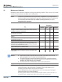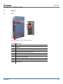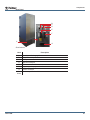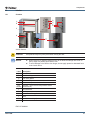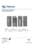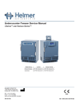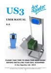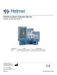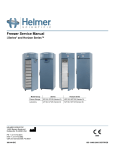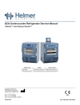
1
Ultra-Low Freezer Operation Manual i .Series® i .Series iUF118, iUF126 (Version A) iUF116, iUF124 (Version A) HELMER SCIENTIFIC 14400 Bergen Boulevard Noblesville, IN 46060 USA PH +1.317.773.9073 FAX +1.317.773.9082 USA and Canada 800.743.5637 360172-A/B ISO 13485:2003 CERTIFIED Document History Revision Date CO Supersession Revision Description A 10 APR 2014* 9339 n/a Initial release. B 12 DEC 2014 10128 B supercedes A Captured product changes prior to product launch * Date submitted for Change Order review. Actual release date may vary. 360172-A/B i Contents Section I: General Information. . . . . . . . . . . . . . . . . . . . . . . . . . . . . . . . . . . . . . . . . 4 1 About this Manual . . . . . . . . . . . . . . . . . . . . . . . . . . . . . . . . . . . . . . . . . . . . . . . . . . . . . . . . . . . 4 1.1 1.2 1.3 Intended Audience. . . . . . . . . . . . . . . . . . . . . . . . . . . . . . . . . . . . . . . . . . . . . . . . . . . . . . . . . . . . . . . . . . . . . . 4 Model References. . . . . . . . . . . . . . . . . . . . . . . . . . . . . . . . . . . . . . . . . . . . . . . . . . . . . . . . . . . . . . . . . . . . . . 4 Copyright and Trademark. . . . . . . . . . . . . . . . . . . . . . . . . . . . . . . . . . . . . . . . . . . . . . . . . . . . . . . . . . . . . . . . 4 2Safety . . . . . . . . . . . . . . . . . . . . . . . . . . . . . . . . . . . . . . . . . . . . . . . . . . . . . . . . . . . . . . . . . . . . . 4 2.1 2.2 2.3 Safety Definitions . . . . . . . . . . . . . . . . . . . . . . . . . . . . . . . . . . . . . . . . . . . . . . . . . . . . . . . . . . . . . . . . . . . . . . 4 Product Labels . . . . . . . . . . . . . . . . . . . . . . . . . . . . . . . . . . . . . . . . . . . . . . . . . . . . . . . . . . . . . . . . . . . . . . . . 5 Avoiding Injury. . . . . . . . . . . . . . . . . . . . . . . . . . . . . . . . . . . . . . . . . . . . . . . . . . . . . . . . . . . . . . . . . . . . . . . . . 5 3 General Recommendations. . . . . . . . . . . . . . . . . . . . . . . . . . . . . . . . . . . . . . . . . . . . . . . . . . . 6 3.1 3.2 3.3 Intended Use. . . . . . . . . . . . . . . . . . . . . . . . . . . . . . . . . . . . . . . . . . . . . . . . . . . . . . . . . . . . . . . . . . . . . . . . . . 6 General Use . . . . . . . . . . . . . . . . . . . . . . . . . . . . . . . . . . . . . . . . . . . . . . . . . . . . . . . . . . . . . . . . . . . . . . . . . . 6 Initial Loading . . . . . . . . . . . . . . . . . . . . . . . . . . . . . . . . . . . . . . . . . . . . . . . . . . . . . . . . . . . . . . . . . . . . . . . . . 6 4 Specifications. . . . . . . . . . . . . . . . . . . . . . . . . . . . . . . . . . . . . . . . . . . . . . . . . . . . . . . . . . . . . . . 6 5Compliance. . . . . . . . . . . . . . . . . . . . . . . . . . . . . . . . . . . . . . . . . . . . . . . . . . . . . . . . . . . . . . . . . 8 5.1 5.2 Regulatory Compliance. . . . . . . . . . . . . . . . . . . . . . . . . . . . . . . . . . . . . . . . . . . . . . . . . . . . . . . . . . . . . . . . . . 8 Electromagnetic Compliance. . . . . . . . . . . . . . . . . . . . . . . . . . . . . . . . . . . . . . . . . . . . . . . . . . . . . . . . . . . . . . 8 Section II: Installation . . . . . . . . . . . . . . . . . . . . . . . . . . . . . . . . . . . . . . . . . . . . . . . 9 6 Location Requirements. . . . . . . . . . . . . . . . . . . . . . . . . . . . . . . . . . . . . . . . . . . . . . . . . . . . . . . 9 6.1Placement. . . . . . . . . . . . . . . . . . . . . . . . . . . . . . . . . . . . . . . . . . . . . . . . . . . . . . . . . . . . . . . . . . . . . . . . . . . . 9 7 Install Components. . . . . . . . . . . . . . . . . . . . . . . . . . . . . . . . . . . . . . . . . . . . . . . . . . . . . . . . . . 9 7.1 7.2 7.3 7.4 Install Rear Stand-Offs . . . . . . . . . . . . . . . . . . . . . . . . . . . . . . . . . . . . . . . . . . . . . . . . . . . . . . . . . . . . . . . . . . 9 Install AC Power Cord Retainer. . . . . . . . . . . . . . . . . . . . . . . . . . . . . . . . . . . . . . . . . . . . . . . . . . . . . . . . . . . 10 Install Shelves. . . . . . . . . . . . . . . . . . . . . . . . . . . . . . . . . . . . . . . . . . . . . . . . . . . . . . . . . . . . . . . . . . . . . . . . . 11 Chart Recorder (Optional). . . . . . . . . . . . . . . . . . . . . . . . . . . . . . . . . . . . . . . . . . . . . . . . . . . . . . . . . . . . . . . 12 7.4.1 Install and Change Chart Paper. . . . . . . . . . . . . . . . . . . . . . . . . . . . . . . . . . . . . . . . . . . . . . . . . . . . 12 Section III: Operation. . . . . . . . . . . . . . . . . . . . . . . . . . . . . . . . . . . . . . . . . . . . . . . 13 8 Initial Start Up. . . . . . . . . . . . . . . . . . . . . . . . . . . . . . . . . . . . . . . . . . . . . . . . . . . . . . . . . . . . . . 13 9 Normal Operation. . . . . . . . . . . . . . . . . . . . . . . . . . . . . . . . . . . . . . . . . . . . . . . . . . . . . . . . . . . 14 9.1 9.2 9.3 9.4 9.5 9.6 Change Temperature Setpoint . . . . . . . . . . . . . . . . . . . . . . . . . . . . . . . . . . . . . . . . . . . . . . . . . . . . . . . . . . . 14 Active Alarms. . . . . . . . . . . . . . . . . . . . . . . . . . . . . . . . . . . . . . . . . . . . . . . . . . . . . . . . . . . . . . . . . . . . . . . . . 14 Mute Active Alarms. . . . . . . . . . . . . . . . . . . . . . . . . . . . . . . . . . . . . . . . . . . . . . . . . . . . . . . . . . . . . . . . . . . . 15 Set Alarm Parameters. . . . . . . . . . . . . . . . . . . . . . . . . . . . . . . . . . . . . . . . . . . . . . . . . . . . . . . . . . . . . . . . . . 15 Access Control . . . . . . . . . . . . . . . . . . . . . . . . . . . . . . . . . . . . . . . . . . . . . . . . . . . . . . . . . . . . . . . . . . . . . . . 16 9.5.1Setup . . . . . . . . . . . . . . . . . . . . . . . . . . . . . . . . . . . . . . . . . . . . . . . . . . . . . . . . . . . . . . . . . . . . . . . . 16 9.5.2 Open Freezer with Access Control. . . . . . . . . . . . . . . . . . . . . . . . . . . . . . . . . . . . . . . . . . . . . . . . . . 17 i.C³® Icon Reference Guide. . . . . . . . . . . . . . . . . . . . . . . . . . . . . . . . . . . . . . . . . . . . . . . . . . . . . . . . . . . . . . 17 360172-A/B ii Section IV: Maintenance . . . . . . . . . . . . . . . . . . . . . . . . . . . . . . . . . . . . . . . . . . . . 18 10 Maintenance Schedule . . . . . . . . . . . . . . . . . . . . . . . . . . . . . . . . . . . . . . . . . . . . . . . . . . . . . . 18 Section V: Components. . . . . . . . . . . . . . . . . . . . . . . . . . . . . . . . . . . . . . . . . . . . . 19 11Exterior. . . . . . . . . . . . . . . . . . . . . . . . . . . . . . . . . . . . . . . . . . . . . . . . . . . . . . . . . . . . . . . . . . . 19 11.1Front . . . . . . . . . . . . . . . . . . . . . . . . . . . . . . . . . . . . . . . . . . . . . . . . . . . . . . . . . . . . . . . . . . . . . . . . . . . . . . . 19 11.2 Rear Panel . . . . . . . . . . . . . . . . . . . . . . . . . . . . . . . . . . . . . . . . . . . . . . . . . . . . . . . . . . . . . . . . . . . . . . . . . . 20 12 Interior. . . . . . . . . . . . . . . . . . . . . . . . . . . . . . . . . . . . . . . . . . . . . . . . . . . . . . . . . . . . . . . . . . . . 21 12.1Chamber. . . . . . . . . . . . . . . . . . . . . . . . . . . . . . . . . . . . . . . . . . . . . . . . . . . . . . . . . . . . . . . . . . . . . . . . . . . . 21 360172-A/B iii General Information Section I: General Information 1 About this Manual 1.1 Intended Audience This manual is intended for use by end users of the freezer and authorized service technicians. 1.2 Model References Generic references are used throughout this manual to group models that contain similar features. For example, “iUF models” refers to all models of that size (iUF116, iUF118, iUF124, iUF126). This manual covers all ultra-low freezers, which may be identified singly, by their size, or by their respective “Series.” 1.3 Copyright and Trademark Helmer®, i.Series®, i.C³®, and Rel.i™ are registered trademarks or trademarks of Helmer, Inc. in the United States of America. Copyright © 2014 Helmer, Inc. All other trademarks and registered trademarks are the property of their respective owners. Helmer, Inc., doing business as (DBA) Helmer Scientific and Helmer. 2Safety The operator or technician performing maintenance or service on Helmer Scientific products must (a) inspect the product for abnormal wear and damage, (b) choose a repair procedure which will not endanger his/her safety, the safety of others, the product, or the safe operation of the product, and (c) fully inspect and test the product to ensure the maintenance or service has been performed properly. 2.1 Safety Definitions The following general safety alerts appear with all safety statements within this manual. Read and abide by the safety statement that accompanies the safety alert symbol. 360172-A/B WARNING The safety statement that follows this safety alert symbol indicates a hazardous situation which, if not avoided, could result in serious injury. CAUTION The safety statement that follows this safety alert symbol indicates a hazardous situation which, if not avoided, could result in minor or moderate injury. NOTICE The safety statement that follows this safety alert symbol indicates a situation which, if not avoided, could result in damage to the product or stored inventory. 4 General Information 2.2 Product Labels The following general safety and information alerts appear on the product to identify potential hazards to the operator or service technician. 2.3 360172-A/B Caution: Safety hazard to operator or service technician Caution: Unlock all casters Caution: Electrocution/shock hazard Earth / ground terminal Caution: Electrostatic discharge (ESD) hazard Protective earth / ground terminal Avoiding Injury ► Review safety instructions before installing, using, or maintaining the equipment. ► Before moving unit, remove contents from the chamber. ► Before moving unit, ensure door is closed and latched, and casters are unlocked and free of debris. ► Before moving unit, disconnect the AC power cord and secure the cord. ► When moving unit, use assistance from a second person. ► Never physically restrict any moving component. ► Avoid removing electrical service panels and access panels unless so instructed. ► Use appropriate gloves when handling cold internal components and stored inventory. ► Keep hands away from pinch points when closing the door. ► Avoid sharp edges when working inside the electrical compartment and refrigeration compartment. ► Ensure biological materials are stored at recommended temperatures determined by standards, literature, or good laboratory practices. ► Proceed with caution when adding and removing samples from the freezer. ► Total freezer weight (including contents) is not to exceed 1400 lbs (635 kg). ► Individual shelf load is not to exceed 160 lbs (73 kg). ► Use supplied power cord only. ► Using the equipment in a manner not specified by Helmer may impair the protection provided by the equipment. ► Decontaminate parts prior to sending for service or repair. Contact Helmer or your distributor for decontamination instructions and a Return Authorization Number. ► Ensure biological materials are stored safely, in accordance with all applicable organizational, regulatory, and legal requirements. ► The freezer is not considered to be a storage cabinet for flammable or hazardous materials. 5 General Information 3 General Recommendations 3.1 Intended Use Helmer ultra-low freezers are intended to provide a controlled temperature environment at ultra-low temperatures required for the storage of biological materials, pharmaceuticals, and reagents used in a research or clinical laboratory. The devices referenced in this manual are intended to be operated by personnel who have procedures in place for meeting FDA, AABB, or any other applicable regulations for the processing and storage of biological materials, pharmaceuticals, and reagents. 3.2 General Use Allow freezer to come to room temperature before switching power on. 3.3 NOTE During initial startup, high temperature alarm may activate while freezer reaches operating temperature. You may want to temporarily change the volume on the audible alarm during this period. NOTE This unit is not a “rapid-freezing” device. Freezing large quantities of liquid, or high-water content items, will temporarily increase the chamber temperature and will cause the compressors to operate for a prolonged period of time. Initial Loading Allow chamber temperature to stabilize at the setpoint before storing pre-frozen product. 4 Specifications iUF116 iUF118 iUF124 iUF126 Standard/English (in) 23.1 x 49.5 x 23.3 23.1 x 54.1 x 23.3 34.4 x 49.5 x 23.3 34.4 x 54.1 x 23.3 Metric (mm) 587 x 1257 x 592 587 x 1374 x 592 874 x 1257 x 592 874 x 1374 x 592 Standard/English (in) 33.8 x 78.2 x 34.8 28.9 x 78.2 x 34.8 45.1 x 78.2 x 34.8 40.2 x 78.2 x 34.8 Metric (mm) 859 x 1986 x 884 734 x 1986 x 884 1146 x 1986 x 884 1021 x 1986 x 884 Standard/English (in) 37.1 x 78.2 x 37.5 32.5 x 78.2 x 37.5 48.4 x 78.2 x 37.5 Metric (mm) 942 x 1986 x 953 826 x 1986 x 953 1229 x 1986 x 953 607 lbs (275 kg) 622 lbs (282 kg) 704 lbs (319 kg) 725 lbs (328 kg) 16 ft³ / 453 L 18 ft³ / 510 L 24 ft³ / 680 L 26 ft³ / 736 L Internal Dimensions (W x H x D) External Dimensions (W x H x D) (1) Overall Dimensions (W x H x D) (2) 43.8 x 78.2 x 37.5 1113 x 1986 x 953 Physical Weight Interior Volume Refrigeration System High Stage Refrigerant R-404A, CFC/HCFC-free Low Stage Refrigerant R-508B, CFC/HCFC-free and R601 natural refrigerant High Stage Compressor 1.5 HP, air-cooled Low Stage Compressor 1.5 HP, air-cooled High Stage Initial Charge Low Stage Initial Charge (R508B) 360172-A/B 48 oz. (1361 g) 13.5 oz. (383 g) 16 oz. (454 g) 6 General Information iUF116 Low Stage Initial Charge (R601) iUF118 iUF124 0.56 oz (26 g) iUF126 0.56 oz (26 g) Operational Default Setpoint -80 ºC (-112 ºF) Temperature Control Range -50 ºC to -86 ºC (-58 ºF to -123 ºF) (1) Includes casters. (2) Includes casters, handle, i.C³ bezel, and door hinges. iUF116 iUF118 iUF124 iUF126 Cabinet Insulation Ecomate® insulating foam (non-ODP, non-GWP, and VOC-exempt blowing agent foam) Vacuum-Insulated Panels (3) Wall Thickness - - 5.0” (127 mm) 2.7” (69 mm) 5.0” (127 mm) 2.7” (69 mm) Door Thickness 2.7” (69 mm) Internal Compartments 4 5 4 5 External Material Galvannealed steel with bacteria-resistant powder-coated finish Internal Material Galvannealed steel with bacteria-resistant powder-coated finish Shelves Stainless steel Maximum Shelf Load 160 lbs (73 kg) External Port 2, standard (top-left corner, rear of cabinet; bottom-left corner, rear of cabinet) Temperature Chart Recorder Optional, 4” (102 mm), 7-day inkless, pressure-sensitive chart paper, backup battery Vacuum Break Port Standard (heated) Electrical Input Voltage 208/230 V, 60 Hz Voltage Tolerance ±10% Circuit Breakers 12 A (quantity 2) Current Draw (4) 11.0 A Energy Consumption 18.5 kWh/day Power Source 18.5 kWh/day 19 kWh/day 19 kWh/day 15 A dedicated circuit Boost Cut-In Voltage (5) 195 V Monitoring System Battery 12 V, 7 Ah rechargeable sealed lead acid battery Chart Recorder Battery Powered from the monitoring system battery Temperature Monitor Accuracy Chart Recorder i.C³ Monitor ±0.5 °C (0.9 °F) ±0.5 °C (0.9 °F) at setpoint Control and Monitoring Interface Alarms 360172-A/B i.C³® combined monitoring and control interface, 7” color LCD touchscreen User-configurable: High chamber temperature, low chamber temperature, power failure, door open (time), high ambient temperature, low ambient temperature Non-configurable: Compressor temperature, condenser temperature, clean filter, CO2 / LN2 active, low battery, no battery, refrigeration system, communication failure, sensor failure Remote Alarm Interface Dry contacts (configurable as normally-open or normally-closed) Remote Alarm Capacity 0.5 A at 30 V (RMS); 1.0 A at 60 V (DC) 7 General Information iUF116 iUF118 iUF124 iUF126 Environmental Operating Standards ► ► ► ► Indoor use only Altitude (maximum): 2000 m Ambient temperature range: 15 ºC to 32 ºC Relative humidity (maximum for ambient temperature): up to 80% for temperatures up to 25 ºC, decreasing linearly to 53% at 32 ºC (3) Vacuum-insulated panels are included in cabinet walls on indicated models. All models feature vacuum-insulated panels in the exterior door. (4) Current draw is measured in full-load Amperes. (5) Power conditioning (voltage boost) is an optional feature. If facility voltage is consistently at or below 195V, voltage boost must be installed in order to protect the compressors. CAUTION Maximum shelf load is not to exceed 160 lbs (73 kg). CAUTION ► The interface on the remote alarm monitoring system is intended for connection to the end user’s central alarm system(s) that uses normally-open or normally-closed dry contacts. ► If an external power supply exceeding 30 V (RMS) or 60 V (DC) is connected to the remote alarm monitoring system’s circuit, the remote alarm will not function properly; may be damaged; or may result in injury to the user. NOTE In the event of a power failure, the power failure alarm condition is transmitted through the remote alarm contacts. 5Compliance 5.1 Regulatory Compliance This product is certified to applicable UL and CSA standards by a NRTL Sound level is less than 70 dB(A). 5.2 Electromagnetic Compliance This device is suitable for use in a specific electromagnetic environment. The end user of this device is responsible for ensuring the device is used in compliance with the following European Union directives and standards regarding EMC (electromagnetic compliance): EMC Directive (2004/108/EC) Standards: ► EN 55011:2009 ► EN 61000-3-2:2006 ► EN 61000-3-3:2008 ► EN 61000-6-1:2007 360172-A/B 8 Installation Section II: Installation 6 Location Requirements ► Has a dedicated 15 A grounded circuit with dedicated single point receptical meeting the electrical requirements listed on the product specification label. ► Is clear of direct sunlight, high temperature sources, and heating and air conditioning vents. ► Minimum 8” (203 mm) above, and minimum 4” (102 mm) behind. ► Meets limits specified for ambient temperature and relative humidity. 6.1Placement WARNING ► To prevent tipping, ensure door is closed and latched, and casters are unlocked and free of debris before moving freezer. ► The freezer is extremely heavy. Helmer recommends that two people work together to move the freezer. 1 Ensure all casters are unlocked and door is closed and latched. 2 Roll freezer into place and lock casters. 3 Adjust leveling feet as necessary to ensure freezer is level. 7 Install Components 7.1 Install Rear Stand-Offs WARNING The rear stand-offs include a hole to accept a threaded fastener for anchoring the freezer to a wall. The rear stand-offs do not provide a secure means to anchor the freezer to the wall that can be considered resistant to seismic events. NOTE ► Installation of the rear stand-offs is optional. ► Anchoring the freezer to the wall is optional. ► Hardware to anchor the freezer to the wall is not provided with the freezer. The end user is responsible for determining the best method to anchor the freezer to the wall. Required tools: ► 9/16” box wrench Rear stand-offs 1 2 3 4 360172-A/B Align the holes in the stand-offs with the corresponding threaded holes on the back of the freezer. Insert the 3/8” hex head cap screws through the holes in the stand-offs. Hand-thread the cap screws into the threaded holes. Using a 9/16” open-ended wrench, tighten the cap screws. 9 Installation 7.2 Install AC Power Cord Retainer WARNING Use supplied power cord only. NOTICE Do not position the freezer where it will prevent access to the power cord disconnect, at the power outlet on the wall. Required tools: ► #2 Phillips screwdriver Install the retainer: 1 Insert the power cord into the receptacle on rear of the cabinet. 2 Install the power cord retainer. a Slide the retainer upward, engaging the groove in the power plug with the slot in the retainer. b Align the holes in the retainer with the corresponding holes on the cabinet. c Insert the screws with lock washers through the retainer and into the holes in the cabinet. d Using a #2 Phillips screwdriver, tighten the screws. Power cord retainer. 360172-A/B 10 Installation 7 .3 Install Shelves Install the shelf clips: 1 Open the chamber door and all inner doors. 2 Install shelf clips on the shelf standards at the marked locations. Shelf clip. NOTE Shelf clips must be installed so the horizontal section is oriented upward. Install the shelves: 1 Starting with the bottom shelf, insert the shelf into the chamber at an angle. 2 Rotatetheshelfsoitsetsflatontheshelfclips. Installed shelves. 3 4 360172-A/B Working from the bottom to the top, install the remaining shelves as described in steps 1 and 2. Close the inner doors and the chamber door. 11 Installation 7.4 Chart Recorder (Optional) A B C D E Chart recorder with paper installed. Label 7.4.1 Description Function A Left and Right Arrow Adjust settings and stylus position buttons B LED C Chart change button Adjust position of stylus when changing chart paper, or run a test pattern D Stylus Mark temperature line on paper E Reset button (located behind chart paper) Restart chart recorder Indicates status of chart recorder in operating mode, or selected temperature range in paper change mode Install and Change Chart Paper 1 Press and hold C button. When stylus begins to move left, release button. The LED flashes to indicate current temperature range. 2 When stylus stops moving, remove chart knob then move knob up and away from chart paper. 3 Place new chart paper on chart recorder. 4 Gently lift stylus and rotate paper so current time line corresponds to time line groove. 5 Hold chart paper and reinstall chart knob. NOTE For accurate temperature reading, ensure that current time is aligned with time line groove when chart knob is tightened. 6 Press and hold C button. When the stylus begins to move right, release the button. 7 Confirm the stylus is marking the temperature correctly. 360172-A/B 12 Operation Section III: Operation 8 Initial Start Up 1 2 3 Plug the power cord into a 15 A grounded circuit with a dedicated single point receptical. Switch battery ON/OFF switch ON. Switch AC ON/OFF switch ON. NOTE 4 Touch the Home button. NOTE 5 360172-A/B The i.C³ monitoring and control system will take approximately three minutes to boot up. Active alarms are displayed on the Home screen. If an alarm condition other than High Temperature occurs, refer to the service manual for troubleshooting. If an alarm activates, temporarily mute the alarm by touching the Mute button. 13 Operation 9 Normal Operation The i.C³ Home screen displays temperature and alarm information, and provides icons for reaching other functions of the i.C³. Home screen. 9 .1 Home screen temperature graph screensaver (touch to return to Home screen). Change Temperature Setpoint ► Enter the Settings password. ► Touch + or – on the spin box to change the value. > NOTE 9 .2 ► Default Settings password is 1234 ► Default setpoint is -80.0 °C Active Alarms Home screen with no alarms. Alarm 360172-A/B Home screen with active alarm. Description High Temperature Chamber temperature reading is above high temperature alarm setpoint Low Temperature Chamber temperature reading is below low temperature alarm setpoint Door Open Doorisopenbeyonduser-specifiedduration High Ambient Ambient temperature reading is above high ambient alarm setpoint Low Ambient Ambient temperature reading is below low ambient alarm setpoint Clean Filter Condenserfilterisobstructed CO2 / LN2 Active CO2 / LN2 backup refrigeration system is active 14 Operation Low Battery Backup battery voltage is low No Battery Backup battery voltage is too low or battery is disconnected Power Failure Power to unit has been disrupted Sensor Failure Sensor not functioning properly Refrigeration System ► ► ► ► ► Refrigerant pressure is too high High stage compressor temperature is above the upper limit Low stage compressor temperature is above the upper limit High stage compressor has failed Low stage compressor has failed Communication Failure Messages 1, 2, 3 1 2 Communication lost between i.C³ display board and control board Communication lost between i.C³ display board and internal system memory Corrupt database 3 Emergency Mode 9 .3 Chamber temperature sensor has failed (or is failing intermittently) and refrigeration system is operating at 100% duty cycle Mute Active Alarms Audible alarms may be muted by touching the Mute button to set delay. :15 Unmuted 9 .4 Muted Set Alarm Parameters The following alarm settings may be changed by the operator. The setpoint for temperature alarms may be changed (where applicable), as well as the time delay between when the alarm condition commences and when the visual and audible alarms are initiated. > ► Enter the Settings password. ► Touch Alarm Settings. ► Controls the conditions and timing of alarm condition indicators displayed on the i.C³ Home screen. Touch + or – on spin box to set each parameter. Alarm Description Default Time Delay High Temperature Chamber temperature reading is above high temperature -70.0 °C alarm setpoint 0 minutes Low Temperature Chamber temperature reading is below low temperature alarm setpoint -90.0 °C 0 minutes Power Failure Power to unit has been disrupted n/a 1 minute Sensor Failure i.C³ control and monitoring system has lost communication n/a with a temperature sensor Door Open (Time) Doorisopenbeyonduser-specifiedduration 360172-A/B Default Setpoint n/a 0 minutes 1 minute 15 Operation Alarm 9 .5 Default Setpoint Description Default Time Delay High Ambient Ambient temperature reading is above high ambient alarm 30.0 °C setpoint 15 minutes Low Ambient Ambient temperature reading is below low ambient alarm setpoint 15 minutes 15.0 °C Access Control Allowsuser-specificsecureaccesstothefreezer. 9 .5 .1 Setup > > > Access Setup Configureandmanageuser-specificaccountstoallow controlled access to the freezer. ► Enter the supervisor PIN to set up Access Control. ► Initial factory supervisor PIN = 5625 NOTE ► The supervisor PIN can not be deleted, and should be changed to prevent unauthorized user ID setup. The supervisor PIN does not allow access to the unit. At least one user ID must be set up to gain access to the unit. ► The keys provided with the freezer may be used to lock or unlock the exterior door. ► When setting up Access Control user IDs, ensure the key lock is in the locked position to prevent unauthorized access to the freezer. Addauserprofile: 1 Touch the Add User button. ► The alphanumeric keyboard is displayed. 2 EntertheuserIDforthenewuserprofile. 3 Touch to store the user ID. 360172-A/B 16 Operation 4 5 ► The alphanumeric keyboard is displayed. Enterthefour-digitPINforthenewuserprofile. Touch to store the PIN. ► TheUserIDandPINforthenewuserprofileisdisplayedinthetable. NOTE 9 .5 .2 Forcompleteinformationonsettingup,editing,anddeletingAccessControluserprofiles, refer to the i.C³ User Guide for i.Series Ultra-Low Freezers. Open Freezer with Access Control ► Enter a valid PIN using the keypad. 9 .6 360172-A/B i .C³® Icon Reference Guide Home Mute Brightness Setting Event Log Download Scroll Arrows Settings Upload Access Control i.C³ Applications Temperature Graph Access Log Back Arrow Information Log Contact Helmer Alarm Conditions Icon Transfer Battery Power 17 Maintenance Section IV: Maintenance 10 Maintenance Schedule Maintenance tasks should be completed according to the following schedule. Refer to the service manual and the i.C³ User Guide for more detail on the various tasks. NOTE These are recommended minimum requirements. Regulations for your organization or physical conditions at your organization may require maintenance items to be performed more frequently (as dictated by facility standard operating procedures), or only by designated service personnel. Task Frequency 3 months 1 year Verify the monitor/chamber temperature sensor accuracy. Calibrate the sensor if necessary. Verify the ambient temperature sensor accuracy. Calibrate the sensor if necessary. Test the High and Low chamber and Ambient Temperature alarms. 2 years Test the Power Failure alarm (as required by your organization’s protocols). Inspect electrical components and wiring terminals in the electrical box for discoloration. Contact Helmer Technical Service if any discoloration is found. Replace the i.C backup battery 3 Defrost and clean the chamber, exterior door gasket, and inner doors. 360172-A/B Test the Door Open alarm. Inspect and clean the condenser filter. As Needed NOTICE ► Inspect and clean the condenser filter as directed in the maintenance schedule, or when prompted by the i.C³ control and monitoring system. ► The Clean Filter alarm monitors the condition of the air filter as a safety measure. The alarm is designed to warn if the filter media becomes clogged such that freezer operation and product integrity will be affected. ► The Clean Filter alarm could indicate a failure of the condenser fan. NOTE ► During a power failure, the backup battery provides power to the monitoring system, power failure alarm, and chart recorder (if equipped). If the backup battery is not functioning, the power failure alarm will not be activated. ► If the backup battery does not provide power to the monitoring system during the power failure alarm test, replace the battery. ► During a power failure, the Access Control lock will continue to secure the door. To access the freezer during a power failure, the override key must be used. 18 Components Section V: Components 11Exterior 11.1Front A B H C I J D E F G Left: Front features. Right: Side panel detail. Label A i.C³ user interface B USB port C Door handle with key lock, electronic lock, and padlock hasp D Condenser grill and filter media E Side panel (refer to side panel detail) F Temperature Chart recorder (optional) G Caster H AC ON/OFF power switch I Circuit breakers J Monitoring system backup battery ON/OFF switch Not shown 360172-A/B Description Leveling feet 19 11 .2 Components Rear Panel B C D E F A G Rear features. Label Condenser discharge grill B RJ-45 Ethernet port C USB port D RS-232 serial port E Remote alarm interface F LN2 / CO2 backup system interface G Power connector Not shown 360172-A/B Description A Productspecificationlabel 20 Components 12 Interior 12 .1 Chamber D E F G A B C H J K I Interior features. CAUTION Keep hands away from pinch points when closing the door. NOTICE ► When removing or replacing storage racks, do not allow the storage rack to set on the top edge of a partially-open interior door. ► To avoid damage to the interior door hinges, do not apply upward or downward force to the interior doors. Label Description A Inner door B Inner door hinge C Inner door gasket D Chamber temperature sensor cover E Chamber temperature sensor wire cover Not Chamber / chart recorder temperature sensor shown (behind cover) F Shelf standard G Shelf clip H Inner door mullion gasket I Shelf J Inner door retaining clip K Inner door catch END OF MANUAL 360172-A/B 21 HELMER SCIENTIFIC 14400 Bergen Boulevard Noblesville, IN 46060 USA PH +1.317.773.9073 FAX +1.317.773.9082 www.helmerinc.com