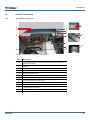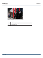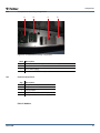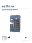
1
Compartmental Access Refrigerator
Operation Manual
HELMER SCIENTIFIC
14400 Bergen Boulevard
Noblesville, IN 46060 USA
PH +1.317.773.9073
FAX +1.317.773.9082
USA and Canada 800.743.5637
360178-A/B
0086
ISO 13485:2003 CERTIFIED
Document History
Revision
Date
CO
Supersession
Revision Description
A
26 JAN 2015
10292 n/a
Initial release.
B
9 FEB 2015
10363 A
Revised product labeling per regulatory requirements.
* Date submitted for Change Order review. Actual release date may vary.
Notes and Disclaimers
Confidential / Proprietary Notices
Use of any portion(s) of this document to copy, translate, disassemble or decompile, or create or attempt
to create by reverse engineering or otherwise the information from Helmer Scientific products is expressly
prohibited.
Disclaimer
This manual is intended as a guide to provide the operator with necessary instructions on the proper use
and maintenance of certain Helmer Scientific products.
Any failure to follow the instructions as described could result in impaired product function, injury to the
operator or others, or void applicable product warranties. Helmer Scientific accepts no responsibility for
liability resulting from improper use or maintenance of its products.
The screenshots and component images appearing in this guide are provided for illustrative purposes
only, and may vary slightly from the actual software screens and/or product components.
Document Updates
The document is furnished for information use only, is subject to change without notice and should not be
construed as a commitment by Helmer Scientific. Helmer Scientific assumes no responsibility or liability
for any errors or inaccuracies that may appear in the informational content contained in this material. For
the purpose of clarity, Helmer Scientific considers only the most recent revision of this document to be
valid.
360178-A/B
i
Contents
Notes and Disclaimers . . . . . . . . . . . . . . . . . . . . . . . . . . . . . . . . . . . . . . . . . . . . . . . i
Section I: General Information. . . . . . . . . . . . . . . . . . . . . . . . . . . . . . . . . . . . . . . . . 4
1 About this Manual . . . . . . . . . . . . . . . . . . . . . . . . . . . . . . . . . . . . . . . . . . . . . . . . . . . . . . . . . . . 4
1.1
1.2
1.3
Intended Audience. . . . . . . . . . . . . . . . . . . . . . . . . . . . . . . . . . . . . . . . . . . . . . . . . . . . . . . . . . . . . . . . . . . . . . 4
Model References. . . . . . . . . . . . . . . . . . . . . . . . . . . . . . . . . . . . . . . . . . . . . . . . . . . . . . . . . . . . . . . . . . . . . . 4
Copyright and Trademark. . . . . . . . . . . . . . . . . . . . . . . . . . . . . . . . . . . . . . . . . . . . . . . . . . . . . . . . . . . . . . . . 4
2 Safety Precautions. . . . . . . . . . . . . . . . . . . . . . . . . . . . . . . . . . . . . . . . . . . . . . . . . . . . . . . . . . . 4
2.1
2.2
2.3
Safety Definitions . . . . . . . . . . . . . . . . . . . . . . . . . . . . . . . . . . . . . . . . . . . . . . . . . . . . . . . . . . . . . . . . . . . . . . 4
Product Labels . . . . . . . . . . . . . . . . . . . . . . . . . . . . . . . . . . . . . . . . . . . . . . . . . . . . . . . . . . . . . . . . . . . . . . . . 5
Avoiding Injury. . . . . . . . . . . . . . . . . . . . . . . . . . . . . . . . . . . . . . . . . . . . . . . . . . . . . . . . . . . . . . . . . . . . . . . . . 5
3 General Recommendations. . . . . . . . . . . . . . . . . . . . . . . . . . . . . . . . . . . . . . . . . . . . . . . . . . . 6
3.1
3.2
3.3
Intended Use. . . . . . . . . . . . . . . . . . . . . . . . . . . . . . . . . . . . . . . . . . . . . . . . . . . . . . . . . . . . . . . . . . . . . . . . . . 6
General Use . . . . . . . . . . . . . . . . . . . . . . . . . . . . . . . . . . . . . . . . . . . . . . . . . . . . . . . . . . . . . . . . . . . . . . . . . . 6
Initial Loading . . . . . . . . . . . . . . . . . . . . . . . . . . . . . . . . . . . . . . . . . . . . . . . . . . . . . . . . . . . . . . . . . . . . . . . . . 6
4 Specifications. . . . . . . . . . . . . . . . . . . . . . . . . . . . . . . . . . . . . . . . . . . . . . . . . . . . . . . . . . . . . . . 6
5Compliance. . . . . . . . . . . . . . . . . . . . . . . . . . . . . . . . . . . . . . . . . . . . . . . . . . . . . . . . . . . . . . . . . 8
5.1
5.2
5.3
5.4
Regulatory Compliance. . . . . . . . . . . . . . . . . . . . . . . . . . . . . . . . . . . . . . . . . . . . . . . . . . . . . . . . . . . . . . . . . . 8
WEEE Compliance. . . . . . . . . . . . . . . . . . . . . . . . . . . . . . . . . . . . . . . . . . . . . . . . . . . . . . . . . . . . . . . . . . . . . 8
Electromagnetic Compliance. . . . . . . . . . . . . . . . . . . . . . . . . . . . . . . . . . . . . . . . . . . . . . . . . . . . . . . . . . . . . . 8
Manufacturer of Record. . . . . . . . . . . . . . . . . . . . . . . . . . . . . . . . . . . . . . . . . . . . . . . . . . . . . . . . . . . . . . . . . . 8
Section II: Initial Setup . . . . . . . . . . . . . . . . . . . . . . . . . . . . . . . . . . . . . . . . . . . . . . . 9
6 Location Requirements. . . . . . . . . . . . . . . . . . . . . . . . . . . . . . . . . . . . . . . . . . . . . . . . . . . . . . . 9
7 Placement. . . . . . . . . . . . . . . . . . . . . . . . . . . . . . . . . . . . . . . . . . . . . . . . . . . . . . . . . . . . . . . . . . 9
8 Temperature Probes . . . . . . . . . . . . . . . . . . . . . . . . . . . . . . . . . . . . . . . . . . . . . . . . . . . . . . . . . 9
9 Chart Recorder (Optional). . . . . . . . . . . . . . . . . . . . . . . . . . . . . . . . . . . . . . . . . . . . . . . . . . . . 10
9.1
Install and Change Chart Paper . . . . . . . . . . . . . . . . . . . . . . . . . . . . . . . . . . . . . . . . . . . . . . . . . . . . . . . . . . . 11
10 Initial Power-Up . . . . . . . . . . . . . . . . . . . . . . . . . . . . . . . . . . . . . . . . . . . . . . . . . . . . . . . . . . . . 12
Section III: Operation . . . . . . . . . . . . . . . . . . . . . . . . . . . . . . . . . . . . . . . . . . . . . . . 14
11Operation . . . . . . . . . . . . . . . . . . . . . . . . . . . . . . . . . . . . . . . . . . . . . . . . . . . . . . . . . . . . . . . . . 14
11.1
11.2
11.3
11.4
11.5
Normal Operation . . . . . . . . . . . . . . . . . . . . . . . . . . . . . . . . . . . . . . . . . . . . . . . . . . . . . . . . . . . . . . . . . . . . . 14
Active Alarms. . . . . . . . . . . . . . . . . . . . . . . . . . . . . . . . . . . . . . . . . . . . . . . . . . . . . . . . . . . . . . . . . . . . . . . . . 14
Mute and Disable Active Alarms. . . . . . . . . . . . . . . . . . . . . . . . . . . . . . . . . . . . . . . . . . . . . . . . . . . . . . . . . . 15
Change Temperature Setpoint . . . . . . . . . . . . . . . . . . . . . . . . . . . . . . . . . . . . . . . . . . . . . . . . . . . . . . . . . . . 15
Set Alarm Parameters. . . . . . . . . . . . . . . . . . . . . . . . . . . . . . . . . . . . . . . . . . . . . . . . . . . . . . . . . . . . . . . . . . 15
12i.C³® Icon Reference Guide. . . . . . . . . . . . . . . . . . . . . . . . . . . . . . . . . . . . . . . . . . . . . . . . . . . 15
13 Operation of Compartment Assembly Components . . . . . . . . . . . . . . . . . . . . . . . . . . . . . . 16
13.1 Compartment Locations . . . . . . . . . . . . . . . . . . . . . . . . . . . . . . . . . . . . . . . . . . . . . . . . . . . . . . . . . . . . . . . . 16
360178-A/B
ii
13.2 Tray Operation . . . . . . . . . . . . . . . . . . . . . . . . . . . . . . . . . . . . . . . . . . . . . . . . . . . . . . . . . . . . . . . . . . . . . . . 16
13.3 Refrigerator Light. . . . . . . . . . . . . . . . . . . . . . . . . . . . . . . . . . . . . . . . . . . . . . . . . . . . . . . . . . . . . . . . . . . . . . 16
14 Operation During a Power Failure . . . . . . . . . . . . . . . . . . . . . . . . . . . . . . . . . . . . . . . . . . . . . 17
14.1 Operating the Refrigerator on an Emergency Power System. . . . . . . . . . . . . . . . . . . . . . . . . . . . . . . . . . . . 18
14.2 Access the Refrigerator and Trays During a Power Failure . . . . . . . . . . . . . . . . . . . . . . . . . . . . . . . . . . . . . 18
14.3 Secure the Exterior Door During an Extended AC Power Failure (optional). . . . . . . . . . . . . . . . . . . . . . . . . 19
Section IV: Maintenance . . . . . . . . . . . . . . . . . . . . . . . . . . . . . . . . . . . . . . . . . . . . 20
15 Maintenance Schedule . . . . . . . . . . . . . . . . . . . . . . . . . . . . . . . . . . . . . . . . . . . . . . . . . . . . . . 20
Section V: Components. . . . . . . . . . . . . . . . . . . . . . . . . . . . . . . . . . . . . . . . . . . . . 21
16 Front Components. . . . . . . . . . . . . . . . . . . . . . . . . . . . . . . . . . . . . . . . . . . . . . . . . . . . . . . . . . 21
16.1 Front Exterior. . . . . . . . . . . . . . . . . . . . . . . . . . . . . . . . . . . . . . . . . . . . . . . . . . . . . . . . . . . . . . . . . . . . . . . . . 21
16.2 Front Chamber . . . . . . . . . . . . . . . . . . . . . . . . . . . . . . . . . . . . . . . . . . . . . . . . . . . . . . . . . . . . . . . . . . . . . . . 22
17 Rear Components . . . . . . . . . . . . . . . . . . . . . . . . . . . . . . . . . . . . . . . . . . . . . . . . . . . . . . . . . . . . 23
17.1 Rear Exterior. . . . . . . . . . . . . . . . . . . . . . . . . . . . . . . . . . . . . . . . . . . . . . . . . . . . . . . . . . . . . . . . . . . . . . . . . 23
17.2 Rear Chamber . . . . . . . . . . . . . . . . . . . . . . . . . . . . . . . . . . . . . . . . . . . . . . . . . . . . . . . . . . . . . . . . . . . . . . . 24
18 Internal Components. . . . . . . . . . . . . . . . . . . . . . . . . . . . . . . . . . . . . . . . . . . . . . . . . . . . . . . . 25
18.1 Refrigerator Components . . . . . . . . . . . . . . . . . . . . . . . . . . . . . . . . . . . . . . . . . . . . . . . . . . . . . . . . . . . . . . . 25
18.2 Compartment Assembly Components. . . . . . . . . . . . . . . . . . . . . . . . . . . . . . . . . . . . . . . . . . . . . . . . . . . . . . 27
18.3 On-board Spare Parts. . . . . . . . . . . . . . . . . . . . . . . . . . . . . . . . . . . . . . . . . . . . . . . . . . . . . . . . . . . . . . . . . . 27
360178-A/B
iii
General Information
Section I: General Information
1
About this Manual
1.1
Intended Audience
This manual is intended for use by end users of the Compartmental Access System which consists of the
iBX080 refrigerator, ACX001 Access Console, and CCX001 Consumable Cart. For information on how to
use the BloodTrack Courier® software which runs on the BloodTrack® Kiosk and provides blood product
management to the HaemoBank™, please refer to the BloodTrack Courier® User Guide (part number
113463-IE).
1.2
Model References
The Compartmental Access System becomes a HaemoBank™ after the BloodTrack Courier® software
is installed. References are used throughout this manual to denote the individual components of the
HaemoBank™. The iBX080 component is referenced as Compartmental Access Refrigerator. The ACX001
component is referenced as the Access Console, and the CCX001 is referenced as the Consumable Cart.
1.3
Copyright and Trademark
Helmer®, i.Series®, i.C³®, and Rel.i™ are registered trademarks or trademarks of Helmer, Inc. in the
United States of America. Copyright © 2015 Helmer, Inc. BloodTrack®, HaemoBank™ and BloodTrack
Courier® are trademarks of Haemonetics Corporation. All other trademarks and registered trademarks
are the property of their respective owners.
Helmer, Inc., doing business as (DBA) Helmer Scientific and Helmer.
2
Safety Precautions
The operator or user performing maintenance or service on Helmer Scientific products must (a) inspect
the product for abnormal wear and damage, (b) choose a repair procedure which will not endanger his/
her safety, the safety of others, the product, or the safe operation of the product, and (c) fully inspect and
test the product to ensure the maintenance or service has been performed properly.
2.1
Safety Definitions
The following general safety alerts appear with all safety statements within this manual. Read and abide
by the safety statement that accompanies the safety alert symbol.
360178-A/B
DANGER
The safety statement that follows this safety alert symbol indicates a hazardous situation
which, if not avoided, could result in serious injury or death.
WARNING
The safety statement that follows this safety alert symbol indicates a hazardous situation
which, if not avoided, could result in serious injury.
CAUTION
The safety statement that follows this safety alert symbol indicates a hazardous situation
which, if not avoided, could result in minor or moderate injury.
NOTICE
The safety statement that follows this safety alert symbol indicates a situation which, if
not avoided, could result in damage to the product or stored inventory.
4
General Information
2.2
Product Labels
Caution: Risk of damage
to equipment or danger to
operator
Caution: Unlock all casters
Caution: Hot surface
Earth / ground terminal
Caution: Shock/electrical
hazard
Protective earth / ground
terminal
Consult instructions for use
2.3
360178-A/B
Avoiding Injury
► Review safety instructions before installing, using, or maintaining the equipment.
► Before moving unit, ensure door(s) is closed and casters are unlocked and free of debris.
► Do not move a unit whose load exceeds 900 lbs / 408 kg.
► Before moving unit, disconnect the AC power cord and secure the cord.
► Do not disconnect the Access Console while the HaemoBank™ is powered on.
► Never physically restrict any moving component.
► Avoid removing electrical service panels and access panels unless so instructed.
► Keep hands away from pinch points when closing the door.
► Avoid sharp edges when working inside the electrical compartment and refrigeration compartment.
► Avoid staring into the tray illumination LEDs for extended periods of time as eye injury may occur.
► Ensure biological materials are stored at recommended temperatures determined by standards,
literature, or good laboratory practices.
► Proceed with caution when adding and removing samples from the refrigerator.
► Use supplied power cord only.
► Using the equipment in a manner not specified by Helmer Scientific may impair the protection
provided by the equipment.
► Decontaminate parts prior to sending for service or repair. Contact Haemonetics® Corporation
BloodTrack® Customer Support (877.996.7877) or your distributor for decontamination instructions
and a Return Authorization Number.
► Ensure biological materials are stored safely, in accordance with all applicable organizational,
regulatory, and legal requirements.
► The refrigerator is not considered to be a storage cabinet for flammable or hazardous materials.
5
General Information
3
General Recommendations
3.1
Intended Use
The Compartmental Access Refrigerator is intended for the storage of blood products and other medical
and scientific products.
3.2
General Use
Allow refrigerator to come to room temperature before powering on.
NOTE
3.3
During initial pull-down, high temperature alarm may activate while refrigerator reaches
operating temperature.
Initial Loading
Allow chamber temperature to stabilize at the setpoint before storing product.
4
Specifications
Compartmental
Access System
iBX080
ACX001
CCX001
Interior Dimensions Dimensions (w x h x d)
Standard/English
N/A
24.75” x 58.25” x 32
N/A
10.6” x 18” x 21”
Metric
N/A
629 X 1480 X 813
N/A
269 x 457 x 533
Standard/English (in)
43.5” x 79.75” x 40”
29” x 79.7” x 38.1”
14” x 51.5” x 23.6”
14.2” x 27.75” x 21.6”
Metric (mm)
1104 x 2026 x1016
737 x 2024 x 968
356 x 394 x 599
361 x 705 x 549
-
747 lbs (339 kg)
108 lbs (49 kg)
63 lbs (29 kg)
Over Exterior Dimensions (w x h x d)
(includes handle, casters, hinges)
Physical
Refrigerator Weight
Refrigeration System
Refrigerant
R-134A (non-CFC)
Compressor
0.33 HP, air-cooled
Initial Charge
10.1 oz. (286 g)
Operational
Default Set Point
Temperature Control Range
4 °C (39 °F)
2 °C to 10 °C (36 °F to 50 °F)
Cabinet
Insulation
Wall Thickness
2” (51 mm)
Door Thickness
2” (51 mm)
External Material
Galvannealed steel with bacteria-resistant powder-coated finish
Internal Material
Galvannealed steel with bacteria-resistant powder-coated finish
Trays
Tray Capacity
External Top Port
Temperature Chart Recorder
360178-A/B
High-density, non-CFC foam
80 trays
1 blood bag per tray
1 standard
Optional, 4” (102 mm) 7-day inkless, pressure-sensitive chart paper, backup battery
6
General Information
Compartmental
Access System
iBX080
ACX001
CCX001
Electrical
Input Voltage and Frequency
-
Voltage Tolerance
-
115 V (60 Hz); 230 V (50 Hz); 230 V (60 Hz)
N/A
±10%
N/A
Circuit Breakers
-
6 A (230 V models
only, quantity 2)
4 A (All models,
quantity 2)
N/A
Current Draw
-
11.9 A (115 V, 60 Hz)
9.5 A (230 V, 50 Hz)
10.9 A (230 V, 60 Hz)
2.85 A (115 V, 60 Hz)
2.80 A (230 V, 50 Hz)
2.75 A (230 V, 60 Hz)
N/A
Energy Consumption
-
1.37 kW (115 V, 60 Hz)
2.19 kW (230 V, 50 Hz)
2.51 kW (230 V, 60 Hz)
.33 kW (115 V, 60 Hz)
.64 kW (230 V, 50 Hz)
.63 kW (230 V, 60 Hz)
N/A
Grounded outlet, meeting national electric code (NEC) in the U.S. and local electrical
requirements in all locations
Power Source
Control and Monitoring
Interface
i.C³ combined monitoring and control interface, 7” color LCD touchscreen
High, low, and condenser temperature; door open; AC power failure; low battery; no battery;
communication failure
Alarms
Remote Alarm Interface
Dry contacts (standard)
Remote Alarm Capacity
0.5 A at 30 V (RMS); 1.0 A at 60 V (DC)
Backup Battery
12 V, 7 Ah rechargeable sealed lead acid battery (quantity 2)
Environmental
Operating Standards
360178-A/B
►
►
►
►
Indoor use only
Altitude (maximum): 2000 m
Ambient temperature range: 15 °C to 32 °C
Relative humidity (maximum for ambient temperature): 80% for temperatures up to
31 °C, decreasing linearly to 50% at 40 °C
► Overvoltage category: II
► Pollution degree: 2
► Mains supply voltage: ±10% of nominal voltage
CAUTION
► The interface on the remote alarm monitoring system is intended for connection to
the end user’s central alarm system(s) that uses normally-open or normally-closed
dry contacts.
► If an external power supply exceeding 30 V (RMS) or 60 V (DC) is connected to the
remote alarm monitoring system’s circuit, the remote alarm will not function properly;
may be damaged; or may result in injury to the user.
NOTICE
It is strongly recommended that the Compartmental Access Refrigerator be connected to
the emergency power system.
NOTE
In the event of a power failure, the power failure alarm condition is transmitted through
the remote alarm contacts.
7
General Information
5Compliance
5.1
Regulatory Compliance
This product is certified to applicable UL and CSA standards by a NRTL.
This device complies with the requirements of directive 93/42/EEC concerning
Medical Devices, as amended by 2007/47/EC.
0086
Sound level is less than 70 dB(A).
Applies to iBX080 refrigerator only.
EC
REP
5.2
Emergo Europe
Molenstraat 15
2513 BH
The Hague, Netherlands
WEEE Compliance
The WEEE (waste electrical and electronic equipment) symbol (right) indicates
compliance with European Union Directive WEEE 2002/96/EC and
applicable provisions. The directive sets requirements for the labeling and
disposal of certain products in affected countries.
When disposing of this product in countries affected by this directive:
► Do not dispose of this product as unsorted municipal waste
► Collect this product separately
► Use the collection and return systems available locally
For more information on the return, recovery, or recycling of this product, contact your local distributor.
5.3
Electromagnetic Compliance
This device is suitable for use in a specific electromagnetic environment. The end user of this device is
responsible for ensuring the device is used in compliance with the following European Union directives
and standards regarding EMC (electromagnetic compliance):
EMC Directive 2004/108/EC
► EN 55011:2009
► EN 61000-3-2:2006
► EN 61000-3-3:2008
► EN 61000-6-1:2007
5.4
Manufacturer of Record
Helmer Scientific is the manufacturer as defined in 93/42/MDD of the iBX080 and for which the CE mark
on the cover of this manual applies.
Haemonetics Corporation is the manufactuer as defined in 93/42/MDD of the BloodTrack Courier®
software and maintains sole responsibility for placing the HaemoBank™ in its final configuration on the
market.
360178-A/B
8
Initial Setup
Section II: Initial Setup
6
Location Requirements
WARNING
► The Compartmental Access Refrigerator must not be placed in ATEX1 classified zones
as per Directive 99/92/EC (‘ATEX 137’) and Directive 94/9/EC (‘ATEX 95’)
► The Compartmental Access Refrigerator should not be placed in Group 2 medical
rooms (ref CEI 64-8 Standard, part 7).
► The Compartmental Access Refrigerator is classified as IP20 and is not fit for
operation outdoors or in environments that are not protected against atmospheric
agents.
► Has a grounded outlet meeting the electrical requirements stated on the product specification label.
► Meets the limits specified for ambient temperature (15°C to 32°C) and relative humidity (80% for
temperatures up to 31°C, decreasing linearly to 50% at 40°C).
► Is clear of direct sunlight, high temperature sources, heating vents, and air conditioning vents.
► Minimum 8” (203 mm) above, and minimum of 1” (26 mm) behind.
7
Placement
WARNING
To prevent tipping, ensure the casters are unlocked and the doors are closed before
moving the refrigerator.
Place the refrigerator:
1 Remove the refrigerator from the shipping carton.
2 Remove and discard the interior packing material.
3 Remove the accessory package from the refrigerator.
4 Remove all materials from the accessory package and file them in a secure location.
5 Ensure all casters are unlocked and doors are closed.
6 Roll refrigerator into place and lock casters.
7 Ensure refrigerator is level.
8 Ensure that trays are locked in place inside compartments.
NOTE
8
The Access Console must be configured by designated service personnel. Please
refer to the service manual for installation instructions for Access Console configuration,
connecting external monitoring devices, and connecting Access Console AC power and
ethernet cable.
Temperature Probes
NOTICE
Temperature probes are fragile; handle with care.
Prepare probes:
1 Add approximately 4 oz. (120 mL) of product simulation solution to the bottle.
► Solution is a 10:1 ratio of water to glycerin.
2 Tightly screw cap on to the probe bottle.
360178-A/B
9
Initial Setup
3 Place the probe bottle in the holder and insert the probe(s).
Figure 1: Upper probe, probe bottle, and bottle holder.
9
Chart Recorder (Optional)
A B
F
C
D
E
Figure 2: Chart recorder with paper and battery installed.
Label
Description
Function
A
Left and Right Arrow Adjust settings and stylus position
buttons
B
LED
C
Chart change button Adjust position of stylus when changing chart paper, or run a test pattern
D
Stylus
Mark temperature line on paper
E
Reset button
Restart chart recorder
F
Backup battery
Provides power during AC power failure. Connect prior to use.
Indicates status of chart recorder in operating mode, or selected
temperature range in paper change mode
Install backup battery
1 Remove the chart recorder backup battery from the accessory box.
2 Install and connect the battery.
360178-A/B
10
Initial Setup
9.1
Install and Change Chart Paper
Install chart paper:
1 Press and hold C button. When stylus begins to move left, release button. The LED flashes to
indicate current temperature range.
2 When stylus stops moving, remove chart knob then move knob up and away from chart paper.
3 Place new chart paper on chart recorder.
4 Gently lift stylus and rotate paper so current time line corresponds to time line groove.
Figure 3: Chart recorder stylus and time line groove.
5 Hold chart paper and reinstall chart knob.
NOTE
For accurate temperature reading, ensure that current time is aligned with time line
groove when chart knob is tightened.
6 Confirm the temperature range is set to the correct value.
7 Press and hold C button. When the stylus begins to move right, release the button.
8 Confirm the stylus is marking the temperature correctly.
360178-A/B
11
Initial Setup
10
Initial Power-Up
NOTE
► The i.C³ monitoring and control system will take approximately three minutes to boot up.
► When the refrigerator is first powered on, the Calibration screen will be displayed.
The calibration screen is not displayed on subsequent power-on events.
Power-up the refrigerator:
1 Switch the refrigerator AC ON/OFF switch ON.
► Switch is located on the electrical box, on top of the refrigerator.
► The i.C³ monitoring and control system powers on and displays the Language screen.
2 Switch the monitoring system / Access Control backup battery ON/OFF switch ON.
► Switch is located on the electrical box, on top of the refrigerator.
Figure 4: AC ON/OFF switch (left), monitoring system / Access Control backup battery ON/OFF switch
(center), circuit breakers (230V systems only) (right).
3 The Start screen is displayed when the i.C3 is powered on. The i.C3 will take approximately three (3)
minutes to boot up.
Figure 5: Start screen.
4 If the high temperature alarm sounds, temporarily mute the alarm by touching the Mute icon.
Figure 6: Mute button.
5 On the Language screen, touch the Language button, then select the preferred language from the
drop-down menu.
► If English is the preferred language, touch the Home button.
360178-A/B
12
Initial Setup
Figure 7: Language screen.
NOTE
Active alarms are displayed on the Home screen. If an alarm condition other than High
Temperature occurs, refer to the service manual for troubleshooting.
Figure 8: Home screen
6 If an alarm sounds, temporarily mute the alarm by touching the Mute button.
:15
Figure 9 (left): Unmuted.
Figure 10 (right): Muted.
360178-A/B
13
Operation
Section III: Operation
11Operation
NOTE
11.1
►
►
Please refer to the i.C3® User Guide for Compartmental Access Refrigerators
for information regarding network communications for BloodTrack®.
Refer to i.C3® User Guide for Compartmental Access Refrigerators for complete information on the User Interface.
Normal Operation
The i.C³ Home screen displays temperature and alarm information, and provides icons for reaching other
functions of the i.C³.
After two minutes of inactivity, the screensaver will be displayed. To return to the Home screen, touch the
screensaver.
Figure 11: Home screen.
11.2
Figure 12: Screensaver.
Active Alarms
Figure 13: Home screen with no alarms.
Alarm
360178-A/B
Figure 14: Home screen with active alarm.
Description
High Temperature
Chamber temperature reading is above high temperature alarm setpoint
Low Temperature
Chamber temperature reading is below low temperature alarm setpoint
Low Battery
Monitoring system / Access Control backup battery voltage is low
Power Failure
Power to unit has been disrupted
Probe Failure
Probe not functioning properly
Door Open
Door is open beyond user-specified duration
14
Operation
Alarm
11.3
Description
Compressor
Temperature
Compressor temperature reading is above high temperature alarm setpoint
Communication
Failure Messages
1, 2, 3
1 Communication lost between i.C³ display board and control board
2 Configuration file is corrupt or i.C³ is unable to access the configuration file
3 Corrupt database
Mute and Disable Active Alarms
Audible alarms may be muted by touching the Mute button to set delay.
Figure 15: Unmuted.
11.4
:15
Figure 16: Muted.
Change Temperature Setpoint
>
NOTE
11.5
► Enter the Settings password.
► Touch + or – on spin box to change value.
► Default Settings password is 1234.
► Default setpoint is 4.0 °C.
Set Alarm Parameters
>
Control the conditions and timing of alarm condition indicators
displayed on the i.C³ Home screen. Touch + or – on spin box to set
> Alarm Settings each parameter.
12i.C³® Icon Reference Guide
360178-A/B
Home
Alarm Test
Icon Transfer
Event Log
(icon-indicator)
Mute
Brightness
Settings
Downloads
Scroll Arrows
i.C³ Applications
(APPS)
Uploads
Access Control
Back Arrow
Temperature
Graph
Contacts
Alarm Conditions
Information Logs
Battery Power
15
Operation
13
Operation of Compartment Assembly Components
13.1
Compartment Locations
Compartment locations are labeled on the matrix (A-D) from left to right across the top and (1-20) from
top to bottom.
Figure 17: Compartment labels.
13.2
Tray Operation
Trays remain locked at all times unless unlocked by the BloodTrack® system.
Trays will be illuminated and unlocked when specified via the BloodTrack® kiosk.
Under normal operation, trays will lock upon full insertion.
A rubber bumper will impede the tray from full extension and removal.
Trays have been designed to contain leaks.
NOTE
13.3
Refer to the Maintenance & Service Manual for instructions on tray removal for cleaning
or replacement.
Refrigerator Light
The refrigerator light is controlled by the BloodTrack® kiosk and cannot be turned on or off via the i.C3
User Interface.
360178-A/B
16
Operation
14
Operation During a Power Failure
The Compartmental Access Refrigerator is equipped with two backup battery systems. One system
provides electrical power to the i.C3 temperature monitoring system, alarm system, magnetic Access
Control door lock, and refrigerator communication boards. A second system provides backup power to
the kiosk, scanner, and speakers. Individual trays cannot be unlocked while the refrigerator is running on
battery power, unless the procedures in Section III, Items 14.3, and 14.4 are performed.
NOTICE
► In the event of a power failure, the backup battery systems do not provide
refrigeration of the chamber or stored product.
► In order to maintain product integrity, follow facility standard operating procedures for
instructions on accessing blood products during a power failure, or for instructions on
moving blood products to a refrigerator operating on an emergency power source.
► If an emergency power source is not available, the temperature of stored blood
products must be checked (according to facility standard operating procedures) to
ensure stored blood products have not warmed to an unacceptable temperature
during a power failure.
► It is strongly recommended that the Compartmental Access Refrigerator be
connected to the emergency power system.
If a main electrical power failure is anticipated to last no longer than 20 minutes, the backup battery
systems will provide temperature monitoring and alarm functions, and will allow secure access to the
refrigerator. However, it will not allow access to the individual trays.
If a power failure is anticipated to last beyond 20 minutes, and the facility has an emergency power
source, refer to Section III, Item 14.1 for instructions on operating the refrigerator after the emergency
power source has come online.
If a power failure is anticipated to last beyond 20 minutes, and the facility does not have an emergency
power source, secure the exterior door and access the refrigerator contents manually (refer to Section III,
Items 14.3 and 14.4).
NOTICE
During a power failure:
► The backup battery does not provide continued refrigeration of the chamber. The
chamber temperature may rise above the established limits necessary to maintain
integrity of stored product.
► The i.C3 backup battery will provide power to the Access Control lock, alarm system,
and communication boards for approximately 20 minutes (the Low Battery alarm will
sound when backup battery power for the refrigerator is nearly depleted).
► While the Access Control magnetic lock is energized, the backup battery is rapidly
depleted.
► The Access Control lock will remain locked until battery power is depleted.
► The i.C3 backup battery provides power to the i.C3 monitoring system, refrigerator
communication components, and Access Control magnetic lock until battery power
is depleted, while the Access Console backup battery provides power to the kiosk,
scanner, and speaker.
During an extended power failure:
► Move the refrigerator main electrical power supply to the facility’s emergency power
system (refer to Section III, Item 14.1), or
► Secure the exterior door, and use the mechanical door key to provide secure storage
for refrigerator contents (refer to Section III, Items 14.3 and 14.4).
360178-A/B
17
Operation
NOTE
14.1
► Each backup battery will provide backup power to their systems for approximately 20
minutes only if the backup battery has been allowed to charge for at least 24 hours
since the last interruption.
► During a power failure, the i.C3 backup battery provides power to the monitoring
system and the power failure alarm. If this backup battery is not functioning, the
power failure alarm will not be activated.
► If the i.C3 backup battery does not provide power to the monitoring system during the
power failure alarm test, replace the battery.
Operating the Refrigerator on an Emergency Power System
Once the emergency power system is online, the Compartmental Access Refrigerator will resume normal
operation.
NOTICE
14.2
► If AC power has failed and the emergency AC power system is started, the
refrigerator will restart using emergency AC power.
► Do not switch the refrigerator backup battery, or Access Console backup battery off if
operating on the emergency AC power system.
► When AC power is restored and the emergency power system is shut down, the
refrigerator will restart using primary AC power.
Access the Refrigerator and Trays During a Power Failure
The Compartmental Access Refrigerator may be accessed in two ways during an AC power failure. While
the refrigerator is operating on backup battery power, the door may be unlocked using the i.C3 monitoring
/ Access Control system. If the backup battery power is depleted, switch the i.C3 monitoring system /
Access Control backup battery ON/OFF switch OFF and the AC power ON/OFF switch OFF. This will
disengage the integrated magnetic lock allowing access to the refrigerator.
DANGER
If blood products are manually removed from the refrigerator during a power failure, it is
the responsibility of the user to follow the facility’s standard operating procedures for safe
transfusion practices. For further guidance, consult your facility’s policies and procedures
for ensuring blood availability in an emergency.
NOTE
Once the i.C3 monitoring system / Access Control backup battery ON/OFF switch is
switched OFF, the contents of the refrigerator will no longer be monitored.
1 Open exterior door.
2 Using the compartment assembly key, unlock the Bypass Release handle.
Figure 20 (left): Bypass Release handle and lock (shown in unlocked position).
Figure 21 (right): Individual tray (shown with blood bag stored in tray).
360178-A/B
18
Operation
3 Rotate the Bypass Release handle counterclockwise to a vertical position to release the locking
mechanism for all trays.
4 Pull out only the tray(s) containing the blood bag(s) to be removed.
5 Remove the blood bag(s) from the tray.
6 Slide the tray into the compartment location until it stops.
7 Rotate the Bypass Release handle clockwise to a horizontal position to secure the locking
mechanism.
8 Using the compartment assembly key, relock the Bypass Release handle.
9 Close the refrigerator door.
10 Switch the backup battery ON/OFF switch ON and the AC power ON/OFF switch ON. (This will
ensure the refrigeration system will restart once AC power is restored.)
14.3
Secure the Exterior Door During an Extended AC Power Failure (optional)
1 Switch the monitoring system / Access Control backup battery ON/OFF switch OFF.
► Switching the backup battery OFF will disable the Access Control door lock and the monitoring
system.
2 Door may be locked using the door key provided with the refrigerator.
3 Remove the key from the exterior door lock.
Figure 18 (left): Monitoring system / Access Control backup battery switch (circled).
Figure 19 (right): Exterior door lock.
360178-A/B
19
Maintenance
Section IV: Maintenance
15
Maintenance Schedule
Maintenance tasks should be completed according to the following schedule. All tasks may be performed
by the end user (with the exception of electrical component and wiring terminal inspection). Refer to the
maintenance & service manual for information on performing the various tasks unless otherwise noted.
NOTE
These are recommended minimum requirements. Regulations for your organization or
physical conditions at your organization may require maintenance items be performed
more frequently, or only by designated personnel.
Frequency
Task
3
months
Test the high and low temperature alarms.
√
Test the power failure alarm.
√
6
months
1
year
2
years
Test the door alarm.
Verify the temperature calibration on the monitor and
change if necessary.
√
√
Check the backup battery for the chart recorder (if
equipped) after an extended power failure and change if
necessary, or change the battery if it has been in service
for 1 year..
√
Inspect solenoids and retighten if necessary (use care
not to stress solenoid to IRACS PCB wires)
√
Inspect electrical components and wiring terminals in
the electrical box for discoloration. Call Haemonetics®
Corporation BloodTrack® Customer Support if any
discoloration is found.
√*
Check the level of the solution in the probe bottle. Refill
or replace solution if necessary.
√
Inspect the probe bottle and clean or replace if
necessary.
√
Check the chamber lights and replace them if necessary.
Clean the condenser grill.
√
√
Clean the door gaskets, interior, and exterior of the refrigerator.
√
Replace tray bumpers in each bin location.
Check the manual bypass lock operation.
As
Needed
√
√
Replace the i.C3 backup battery.
√
Replace the Access Console backup battery.
√
Restock spare on-board parts.
√
NOTICE
Clean the condenser grill on a quarterly basis.
NOTE
Replacement of the tray bumpers requires removal and replacement of the trays. Refer
to the service manual for instructions on removal of trays.
*Must be performed by designated maintenance/service personnel.
360178-A/B
20
Components
Section V: Components
16
Front Components
16.1
Front Exterior
H
A
I
B
L
J
C
D
E
F
G
K
Figure 23: Front exterior features.
Label
360178-A/B
Description
A
Access Console
B
BloodTrack® kiosk
C
Barcode scanner
D
Printer drawer
E
Rotating table
F
Consumable cart
G
Keyed door lock (consumable cart)
H
Chart recorder (optional, not shown)
I
Independent keyed door lock (chamber door)
J
i.C³ user interface
K
Caster
L
USB port (i.C3)
21
Components
16.2
Front Chamber
A
B
C
D
H
I
J
K
E
F
G
Figure 24: Front chamber features.
Label
Description
A
Door switch
B
Chamber light
C
Screen
D
Bypass Release handle and lock
E
Tray (80)
F
Compartment assembly
G
Rubber bumper (80)
H
Upper probe
I
Chart recorder probe (optional)
J
Probe bottle
K
Access Control door lock (inside door frame/handle)
Not
shown
360178-A/B
Unit cooler with fan guard (behind screen)
22
Components
17
Rear Components
17.1
Rear Exterior
B
C
D
E
A
F
G
H
I
J
Figure 25: Rear exterior features.
Label
360178-A/B
Description
A
Keyed door lock
B
Access Console AC power and communication cable routing holes
C
Access Console
D
Access Console AC power and communication connections
(located behind cable routing holes)
E
Access Console USB
F
Access Console RJ45 Ethernet port (2)
G
Access Console backup battery switch
H
Access Console RS232 port
I
Access Console AC power cord receptacle
J
Spare IRACS board (attached to Compartmental Access
Refrigerator top cover)
23
Components
17.2
Rear Chamber
A
B
C
D
E
F
G
H
I
J
Figure 26: Rear chamber features.
Label
360178-A/B
Description
A
Rear door switch
B
Unit cooler with fan guard
C
Recirculation baffle
D
Solenoid (80)
E
IRACS PCBs (20)
F
VIB PCBs (4)
G
Condensate drain line
H
Condensate evaporator power cable
I
Condensate evaporator fan power cable
J
Condensate evaporator and fan (located below cabinet floor)
24
Components
18
Internal Components
18.1
Refrigerator Components
L
A
B
E
F
G
H
C
M
I
J
K
D
A
Figure 27: Refrigeration components (Refrigerator).
Label
360178-A/B
Description
A
RJ-45 Ethernet port (located behind electrical panel; connects to
yellow router ports)
B
USB port
C
Remote alarm interface
D
Compressor
E
System AC power cord
F
AC ON/OFF switch
G
Monitoring system / Access Control backup battery ON/OFF switch
H
Circuit breakers (230V units only)
I
Condenser
J
Monitoring system / Access Control backup battery
K
Condenser fan and motor
L
Product specification label
M
Access port
25
Components
A
B
C
Figure 28: Refrigeration components (Refrigerator).
Label
360178-A/B
Description
A
Condenser temperature probe
B
Condenser fan motor
C
Compressor
26
Components
18.2
Compartment Assembly Components
A
B
C
D
Figure 29: Compartment assembly components.
Label
18.3
Description
A
Compartment assembly control PCB assembly
B
Power distribution board
C
24 V power supply
D
Router with RJ45-Ethernet ports
On-board Spare Parts
Qty
Description
1
Tray
1
Tray lock solenoid
2
Tray bumpers
1
IRACS horizontal board with solenoids
1
PDB power distribution board
END OF MANUAL
360178-A/B
27
HELMER SCIENTIFIC
14400 Bergen Boulevard
Noblesville, IN 46060 USA
PH +1.317.773.9073
FAX +1.317.773.9082
www.helmerinc.com