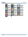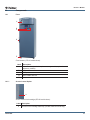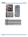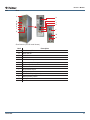
1
Freezer Operation Manual i.Series™ and Horizon Series™ Model Group i.Series Horizon Series Plasma Storage iPF120, iPF125 (Version D) HPF120, HPF125 (Version D) Laboratory iLF120, iLF125 (Version D) HLF120, HLF125 (Version D) HELMER SCIENTIFIC 14400 Bergen Boulevard Noblesville, IN 46060 USA PH +1.317.773.9073 FAX +1.317.773.9082 USA and Canada 800.743.5637 360139-D/A 0086 ISO 13485:2003 CERTIFIED Document History Revision A Date 23 JAN 2013 CO 8187 Supersession n/a Revision Description Initial release. * Date submitted for Change Order review. Actual release date may vary. 360139-D/A i Contents Section I: General Information. . . . . . . . . . . . . . . . . . . . . . . . . . . . . . . . . . . . . . . . . 4 1 About this Manual . . . . . . . . . . . . . . . . . . . . . . . . . . . . . . . . . . . . . . . . . . . . . . . . . . . . . . . . . . . 4 1.1 1.2 1.3 Intended Audience. . . . . . . . . . . . . . . . . . . . . . . . . . . . . . . . . . . . . . . . . . . . . . . . . . . . . . . . . . . . . . . . . . . . . . 4 Model References. . . . . . . . . . . . . . . . . . . . . . . . . . . . . . . . . . . . . . . . . . . . . . . . . . . . . . . . . . . . . . . . . . . . . . 4 Copyright and Trademark. . . . . . . . . . . . . . . . . . . . . . . . . . . . . . . . . . . . . . . . . . . . . . . . . . . . . . . . . . . . . . . . 4 2 Safety . . . . . . . . . . . . . . . . . . . . . . . . . . . . . . . . . . . . . . . . . . . . . . . . . . . . . . . . . . . . . . . . . . . . . 4 2.1 2.2 Labels. . . . . . . . . . . . . . . . . . . . . . . . . . . . . . . . . . . . . . . . . . . . . . . . . . . . . . . . . . . . . . . . . . . . . . . . . . . . . . . 4 Avoiding Injury. . . . . . . . . . . . . . . . . . . . . . . . . . . . . . . . . . . . . . . . . . . . . . . . . . . . . . . . . . . . . . . . . . . . . . . . . 4 3 General Recommendations. . . . . . . . . . . . . . . . . . . . . . . . . . . . . . . . . . . . . . . . . . . . . . . . . . . 5 3.1 3.2 3.3 Intended Use. . . . . . . . . . . . . . . . . . . . . . . . . . . . . . . . . . . . . . . . . . . . . . . . . . . . . . . . . . . . . . . . . . . . . . . . . . 5 General Use . . . . . . . . . . . . . . . . . . . . . . . . . . . . . . . . . . . . . . . . . . . . . . . . . . . . . . . . . . . . . . . . . . . . . . . . . . 5 Initial Loading . . . . . . . . . . . . . . . . . . . . . . . . . . . . . . . . . . . . . . . . . . . . . . . . . . . . . . . . . . . . . . . . . . . . . . . . . 5 4 Operating Standards. . . . . . . . . . . . . . . . . . . . . . . . . . . . . . . . . . . . . . . . . . . . . . . . . . . . . . . . . 5 4.1 4.2 Electrical Specifications. . . . . . . . . . . . . . . . . . . . . . . . . . . . . . . . . . . . . . . . . . . . . . . . . . . . . . . . . . . . . . . . . . 5 Dimensions. . . . . . . . . . . . . . . . . . . . . . . . . . . . . . . . . . . . . . . . . . . . . . . . . . . . . . . . . . . . . . . . . . . . . . . . . . . 6 4.2.1 Weight . . . . . . . . . . . . . . . . . . . . . . . . . . . . . . . . . . . . . . . . . . . . . . . . . . . . . . . . . . . . . . . . . . . . . . . . 6 4.2.2 Size . . . . . . . . . . . . . . . . . . . . . . . . . . . . . . . . . . . . . . . . . . . . . . . . . . . . . . . . . . . . . . . . . . . . . . . . . . 6 5 Regulatory Compliance. . . . . . . . . . . . . . . . . . . . . . . . . . . . . . . . . . . . . . . . . . . . . . . . . . . . . . . 7 6 Installation . . . . . . . . . . . . . . . . . . . . . . . . . . . . . . . . . . . . . . . . . . . . . . . . . . . . . . . . . . . . . . . . . 7 6.1 6.2 6.3 Location Requirements. . . . . . . . . . . . . . . . . . . . . . . . . . . . . . . . . . . . . . . . . . . . . . . . . . . . . . . . . . . . . . . . . . 7 6.1.1 Placement . . . . . . . . . . . . . . . . . . . . . . . . . . . . . . . . . . . . . . . . . . . . . . . . . . . . . . . . . . . . . . . . . . . . . 7 Temperature Probes. . . . . . . . . . . . . . . . . . . . . . . . . . . . . . . . . . . . . . . . . . . . . . . . . . . . . . . . . . . . . . . . . . . . 8 Chart Recorder. . . . . . . . . . . . . . . . . . . . . . . . . . . . . . . . . . . . . . . . . . . . . . . . . . . . . . . . . . . . . . . . . . . . . . . . 8 6.3.1 Install and Change Chart Paper. . . . . . . . . . . . . . . . . . . . . . . . . . . . . . . . . . . . . . . . . . . . . . . . . . . . . 9 7 Maintenance Schedule . . . . . . . . . . . . . . . . . . . . . . . . . . . . . . . . . . . . . . . . . . . . . . . . . . . . . . 10 Section II: i.Series™ Models. . . . . . . . . . . . . . . . . . . . . . . . . . . . . . . . . . . . . . . . . 11 8 Operation . . . . . . . . . . . . . . . . . . . . . . . . . . . . . . . . . . . . . . . . . . . . . . . . . . . . . . . . . . . . . . . . . 11 8.1 8.2 8.3 8.4 8.5 8.6 8.7 Initial Start Up. . . . . . . . . . . . . . . . . . . . . . . . . . . . . . . . . . . . . . . . . . . . . . . . . . . . . . . . . . . . . . . . . . . . . . . . . 11 Change Temperature Setpoint . . . . . . . . . . . . . . . . . . . . . . . . . . . . . . . . . . . . . . . . . . . . . . . . . . . . . . . . . . . . 11 Set Alarm Parameters. . . . . . . . . . . . . . . . . . . . . . . . . . . . . . . . . . . . . . . . . . . . . . . . . . . . . . . . . . . . . . . . . . . 11 Normal Operation . . . . . . . . . . . . . . . . . . . . . . . . . . . . . . . . . . . . . . . . . . . . . . . . . . . . . . . . . . . . . . . . . . . . . 12 Active Alarms. . . . . . . . . . . . . . . . . . . . . . . . . . . . . . . . . . . . . . . . . . . . . . . . . . . . . . . . . . . . . . . . . . . . . . . . . 12 Mute and Disable Active Alarms. . . . . . . . . . . . . . . . . . . . . . . . . . . . . . . . . . . . . . . . . . . . . . . . . . . . . . . . . . 12 Access Control (Optional). . . . . . . . . . . . . . . . . . . . . . . . . . . . . . . . . . . . . . . . . . . . . . . . . . . . . . . . . . . . . . . 13 8.7.1 Setup . . . . . . . . . . . . . . . . . . . . . . . . . . . . . . . . . . . . . . . . . . . . . . . . . . . . . . . . . . . . . . . . . . . . . . . . 13 8.7.2 Open Freezer with Access Control. . . . . . . . . . . . . . . . . . . . . . . . . . . . . . . . . . . . . . . . . . . . . . . . . . 13 9 i.C³® Icon Reference Guide. . . . . . . . . . . . . . . . . . . . . . . . . . . . . . . . . . . . . . . . . . . . . . . . . . . 14 10 Components. . . . . . . . . . . . . . . . . . . . . . . . . . . . . . . . . . . . . . . . . . . . . . . . . . . . . . . . . . . . . . . 15 10.1 Front . . . . . . . . . . . . . . . . . . . . . . . . . . . . . . . . . . . . . . . . . . . . . . . . . . . . . . . . . . . . . . . . . . . . . . . . . . . . . . . 15 10.1.1 Access Control Option. . . . . . . . . . . . . . . . . . . . . . . . . . . . . . . . . . . . . . . . . . . . . . . . . . . . . . . . . . . 15 10.2 Chamber. . . . . . . . . . . . . . . . . . . . . . . . . . . . . . . . . . . . . . . . . . . . . . . . . . . . . . . . . . . . . . . . . . . . . . . . . . . . 16 360139-D/A ii 10.3 Rear. . . . . . . . . . . . . . . . . . . . . . . . . . . . . . . . . . . . . . . . . . . . . . . . . . . . . . . . . . . . . . . . . . . . . . . . . . . . . . . . 17 10.4 Top. . . . . . . . . . . . . . . . . . . . . . . . . . . . . . . . . . . . . . . . . . . . . . . . . . . . . . . . . . . . . . . . . . . . . . . . . . . . . . . . . 18 Section III: Horizon Series™ Models. . . . . . . . . . . . . . . . . . . . . . . . . . . . . . . . . . . 19 11 Operation . . . . . . . . . . . . . . . . . . . . . . . . . . . . . . . . . . . . . . . . . . . . . . . . . . . . . . . . . . . . . . . . . 19 11.1 Initial Start Up. . . . . . . . . . . . . . . . . . . . . . . . . . . . . . . . . . . . . . . . . . . . . . . . . . . . . . . . . . . . . . . . . . . . . . . . 19 11.2 Temperature Setpoints . . . . . . . . . . . . . . . . . . . . . . . . . . . . . . . . . . . . . . . . . . . . . . . . . . . . . . . . . . . . . . . . . 19 11.2.1 Change Setpoint. . . . . . . . . . . . . . . . . . . . . . . . . . . . . . . . . . . . . . . . . . . . . . . . . . . . . . . . . . . . . . . . 19 11.2.2 Monitor Offset. . . . . . . . . . . . . . . . . . . . . . . . . . . . . . . . . . . . . . . . . . . . . . . . . . . . . . . . . . . . . . . . . . 19 11.2.3 Control Sensor Offset. . . . . . . . . . . . . . . . . . . . . . . . . . . . . . . . . . . . . . . . . . . . . . . . . . . . . . . . . . . . 19 11.2.4 Hysteresis. . . . . . . . . . . . . . . . . . . . . . . . . . . . . . . . . . . . . . . . . . . . . . . . . . . . . . . . . . . . . . . . . . . . . 20 11.2.5 Change a Temperature Alarm Setpoint . . . . . . . . . . . . . . . . . . . . . . . . . . . . . . . . . . . . . . . . . . . . . . 20 11.3 Active Alarms. . . . . . . . . . . . . . . . . . . . . . . . . . . . . . . . . . . . . . . . . . . . . . . . . . . . . . . . . . . . . . . . . . . . . . . . . 20 11.4 Mute and Disable Audible Alarms. . . . . . . . . . . . . . . . . . . . . . . . . . . . . . . . . . . . . . . . . . . . . . . . . . . . . . . . . 20 11.5 Access Control (Optional). . . . . . . . . . . . . . . . . . . . . . . . . . . . . . . . . . . . . . . . . . . . . . . . . . . . . . . . . . . . . . . 21 11.5.1 Setup . . . . . . . . . . . . . . . . . . . . . . . . . . . . . . . . . . . . . . . . . . . . . . . . . . . . . . . . . . . . . . . . . . . . . . . . 21 11.5.2 Add User Code. . . . . . . . . . . . . . . . . . . . . . . . . . . . . . . . . . . . . . . . . . . . . . . . . . . . . . . . . . . . . . . . . 21 11.5.3 Delete User Code. . . . . . . . . . . . . . . . . . . . . . . . . . . . . . . . . . . . . . . . . . . . . . . . . . . . . . . . . . . . . . . 21 11.5.4 Open Freezer with Access Control. . . . . . . . . . . . . . . . . . . . . . . . . . . . . . . . . . . . . . . . . . . . . . . . . . 21 12 Components. . . . . . . . . . . . . . . . . . . . . . . . . . . . . . . . . . . . . . . . . . . . . . . . . . . . . . . . . . . . . . . 22 12.1 Front . . . . . . . . . . . . . . . . . . . . . . . . . . . . . . . . . . . . . . . . . . . . . . . . . . . . . . . . . . . . . . . . . . . . . . . . . . . . . . . 22 12.1.1 Access Control Option. . . . . . . . . . . . . . . . . . . . . . . . . . . . . . . . . . . . . . . . . . . . . . . . . . . . . . . . . . . 22 12.2 Chamber. . . . . . . . . . . . . . . . . . . . . . . . . . . . . . . . . . . . . . . . . . . . . . . . . . . . . . . . . . . . . . . . . . . . . . . . . . . . 23 12.3 Rear. . . . . . . . . . . . . . . . . . . . . . . . . . . . . . . . . . . . . . . . . . . . . . . . . . . . . . . . . . . . . . . . . . . . . . . . . . . . . . . . 24 12.4 Top. . . . . . . . . . . . . . . . . . . . . . . . . . . . . . . . . . . . . . . . . . . . . . . . . . . . . . . . . . . . . . . . . . . . . . . . . . . . . . . . . 25 360139-D/A iii General Information Section I: General Information 1 About this Manual 1.1 Intended Audience This manual is intended for use by end users of the freezer and authorized service technicians. 1.2 Model References Generic references are used throughout this manual to group models that contain similar features. For example, “125 models” refers to all models of that size (iPF125, HPF125, iLF125, HLF125). This manual covers all upright freezers, which may be identified singly, by their size, or by their respective “Series.” 1.3 Copyright and Trademark Helmer®, i.Series®, i.C³®, Horizon Series™, and Rel.i™ are registered trademarks or trademarks of Helmer, Inc. in the United States of America. Copyright © 2013 Helmer, Inc. All other trademarks and registered trademarks are the property of their respective owners. Helmer, Inc., doing business as (DBA) Helmer Scientific and Helmer. 2 Safety Includes general safety information for freezer operation. 2.1 Labels 2.2 Caution: Risk of damage to equipment or danger to operator Caution: Unlock all casters Caution: Hot surface Earth / ground terminal Caution: Shock/electrical hazard Protective earth / ground terminal Avoiding Injury ► Review safety instructions before installing, using, or maintaining the equipment. ► Do not open multiple, loaded drawers at the same time. ► Do not move a unit whose load exceeds 900 lbs / 408 kg. ► Before moving unit, ensure casters are free of debris. ► Never physically restrict any moving component. ► Avoid removing electrical service panels and access panels unless so instructed. ► Use supplied power cords only. ! 360139-D/A Caution Decontaminate parts prior to sending for service or repair. Contact Helmer or your distributor for decontamination instructions and a Return Authorization Number. 4 General Information 3 General Recommendations 3.1 Intended Use Helmer freezers are intended for the storage of blood products and other medical and scientific products. 3.2 General Use Allow freezer to come to room temperature before switching power on. During initial startup, high temperature alarm may sound while freezer reaches operating temperature. ! 3.3 Caution Do not remove the cover from the condensate evaporator tray. Initial Loading Allow the freezer to reach room temperature before powering on. Allow chamber temperature to stabilize at the setpoint before storing product. 4 Operating Standards These units are designed to operate under the following environmental conditions: ► Indoor use only ► Altitude (maximum): 2000 m ► Ambient temperature range: 15 ºC to 32 ºC ► Relative humidity (maximum for ambient temperature): 80% for temperatures up to 31 ºC, decreasing linearly to 50% at 40 ºC ► Temperature control range: -15 ºC to -30 ºC 4.1 Electrical Specifications Refer to specification label for voltage and power consumption requirements. Voltage tolerance is ±10%. Power consumption is measured in full load Amperes. Input Voltage Power Consumption 230 V, 50 Hz 3.8 A 208/230 V, 60 Hz 4.3 A Circuit Breakers 12.0 A (quantity 2) The terminals on the remote alarm interface have the following maximum load capacity: ► 0.5 A at 125 V (AC): 1 A at 250 V (DC) 360139-D/A 5 General Information 4.2 Dimensions 4.2.1 Weight Note The weight may vary slightly depending on installed options. Weights provided are for standard configurations as shown. Model Variety Model Family 120 125 iPF 8 drawers 8 drawers iLF 4 shelves 8 shelves HPF 8 drawers 8 drawers HLF 4 shelves 8 shelves Model Variety Model Family 120 125 iPF 505 lbs 230 kg 557 lbs 253 kg iLF 443 lbs 201 kg 481 lbs 219 kg HPF 502 lbs 228 kg 554 lbs 252 kg HLF 440 lbs 200 kg 478 lbs 217 kg Note 4.2.2 Maximum load per drawer is 100 lbs / 45 kg Size All dimensions are for the overall exterior and include items that protrude from the main unit. i.Series Model Family Width Height Depth Width Height Depth 120 30.75” 782 mm 80” 2032 mm 80” 2032 mm 29.5” 750 mm 78.75” 2001 mm 32.5” 826 mm 125 30.75” 782 mm 32.50” 826 mm 38.50” 978 mm 29.5” 750 mm 78.75” 2001 mm 38.5” 978 mm Note 360139-D/A Horizon Series Add 1.50” (39 mm) to the width of all freezers equipped with the Access Control option. 6 General Information 5 Regulatory Compliance This device complies with the requirements of directive 93/42/EEC concerning Medical Devices, as amended by 2007/47/EC. Sound level is less than 70 dB(A). EC REP 0086 Emergo Europe Molenstraat 15 2513 BH The Hague, Netherlands WEEE Compliance The WEEE (waste electrical and electronic equipment) symbol (right) indicates compliance with European Union Directive WEEE 2002/96/EC and applicable provisions. The directive sets requirements for the labeling and disposal of certain products in affected countries. When disposing of this product in countries affected by this directive: ► Do not dispose of this product as unsorted municipal waste. ► Collect this product separately. ► Use the collection and return systems available locally. For more information on the return, recovery, or recycling of this product, contact your local distributor. 6 Installation 6.1 Location Requirements ► Has a grounded outlet meeting the electrical requirements listed on the product specification label. ► Is clear of direct sunlight, high temperature sources, and heating and air conditioning vents. ► Minimum 8” (203 mm) above, and minimum 3” (76 mm) behind. ► Meets limits specified for ambient temperature and relative humidity. 6.1.1 Placement ! Caution 1 2 3 Ensure all casters are unlocked and doors are closed. Roll freezer into place and lock casters. Ensure freezer is level. Note 360139-D/A ► Do not use the water evaporation tray, located on the rear of the freezer, as a handle. The tray may be hot. ► To prevent tipping, ensure the casters are unlocked, leveling feet (if installed) are lifted, and the doors are closed before moving the freezer. Helmer recommends the use of leveling feet. 7 General Information 6.2 Temperature Probes For each probe bottle, use: ► Approximately 4 oz (120 ml) of product simulation solution (1:1 ratio of water to propylene glycol). 6.3 Chart Recorder A B F C D E Chart recorder with paper and battery installed. Label 360139-D/A Description Function A Left and Right Arrow Adjust settings and stylus position buttons B LED C Chart change button Adjust position of stylus when changing chart paper, or run a test pattern D Stylus Mark temperature line on paper E Reset button Restart chart recorder F Backup battery Provides power during AC power failure. Connect prior to use. Indicates status of chart recorder in operating mode, or selected temperature range in paper change mode 8 General Information 6.3.1 Install and Change Chart Paper 1 Press and hold C button. When stylus begins to move left, release button. The LED flashes to indicate current temperature range. 2 When stylus stops moving, remove chart knob then move knob up and away from chart paper. 3 Place new chart paper on chart recorder. 4 Gently lift stylus and rotate paper so current time line corresponds to time line groove. 5 Hold chart paper and reinstall chart knob. Note 6 7 8 360139-D/A ► For accurate temperature reading, ensure that current time is aligned with time line groove when chart knob is tightened. ► Do not overtighten knob. Confirm the temperature range is set to the correct value. Press and hold C button. When the stylus begins to move right, release the button. Confirm the stylus is marking the temperature correctly. 9 General Information 7 Maintenance Schedule Maintenance tasks should be completed according to the following schedule. Refer to the service manual and the i.C³ User Guide for more detail on the various tasks. Note These are recommended minimum requirements. Regulations for your organization or physical conditions at your organization may require maintenance items to be performed more frequently, or only by designated service personnel. Task Frequency Quarterly Test the high and low temperature alarms. Test the power failure alarm (as required by your organization’s protocols). Annually (Horizon Series) (i.Series) Test the door alarm (as required by your organization’s protocols). Check the temperature calibration on the monitor and change it if necessary. (Models with chart recorders) Check the backup battery for the chart recorder after an extended power failure and change it if necessary, or change the battery if it has been in service for 1 year. Refer to the Temperature Chart Recorder Operation and Service Manual. Check the level of the solution in the probe bottles. Refill or replace solution if necessary. Examine the probe bottles and clean or replace if necessary. Clean the condenser grill. 360139-D/A As Needed Clean the door gaskets, interior, and exterior of the freezer. If applicable, test the ground fault circuit interrupter on the internal outlet. Note Clean the condenser grill on a quarterly basis. Note ► During a power failure, the backup battery provides power to the monitoring system and the power failure alarm. If the backup battery is not functioning, the power failure alarm will not be activated. ► If the backup battery does not provide power to the monitoring system during the power failure alarm test, replace the battery. ► i.Series: If rechargeable battery has been in service for 2 years, replace battery. ► Horizon Series: If battery has been in service for 1 year, replace battery. 10 i.Series™ Models Section II: i.Series™ Models 8 Operation 8.1 Initial Start Up 1 Plug the power cord into a grounded outlet that meets the electrical requirements on the product specification label. 2 Switch AC ON/OFF switch ON. 3 Switch backup battery switch ON. Note 4 The i.C³ monitoring and control system will take approximately 2 minutes to boot up. Select language. Note 5 8.2 Active alarms are displayed on the Home screen. If an alarm condition other than High Temperature occurs, refer to the service manual for troubleshooting. If an alarm sounds, temporarily mute the alarm by touching the Mute button. Change Temperature Setpoint > Touch + or – on spin box to change value. Note 8.3 Default setpoint is -30.0 ºC Set Alarm Parameters > 360139-D/A Control the conditions and timing of alarm condition indicators displayed on the i.C³ Home screen. Touch + or – on spin box to set > Alarm Settings each parameter. 11 i.Series™ Models 8.4Normal Operation The i.C³ Home screen displays temperature and alarm information, and provides icons for reaching other functions of the i.C³. Home screen 8.5 Home screensaver (touch to return to Home screen) Active Alarms Home with no alarms Alarm 8.6 Home with active alarm Description High Temperature Chamber temperature reading is above high temperature alarm setpoint Low Temperature Chamber temperature reading is below low temperature alarm setpoint Low Battery Rechargeable battery voltage is low Power Failure Power to unit has been disrupted Probe Failure Probe not functioning properly Door Open Door is open beyond user-specified duration Compressor Temperature Compressor temperature reading is above high temperature alarm setpoint Communication Failure Messages 1, 2, 3 1 2 3 Communication lost between i.C³ display board and control board Communication lost between i.C³ display board and internal system memory Corrupt database Mute and Disable Active Alarms Audible alarms may be muted by touching the Mute button to set delay. :15 Unmuted 360139-D/A Muted 12 i.Series™ Models 8.7 Access Control (Optional) Allows user-specific secure access to the freezer. 8.7.1 Setup > > > Access Setup Configure and manage use-specific accounts to allow controlled access to the freezer. ► Enter the supervisor PIN to set up Access Control. ► Initial factory supervisor PIN = 5625 Note 8.7.2 The supervisor PIN can not be deleted, and should be changed to prevent unauthorized user ID setup. The supervisor PIN does not allow access to the unit. At least 1 user ID must be set up to gain access to the unit. Open Freezer with Access Control ► Enter a valid PIN using the keypad. 360139-D/A 13 i.Series™ Models 9 i.C³® Icon Reference Guide Home Download Scroll Arrows Event Log Upload Defrost Cycle Settings Temperature Graph Defrost Log i.C³ Applications Information Log Access Control Back Arrow Compressor Log Access Control Log Alarm Conditions Icon Transfer Contact Helmer Alarm Test Display Brightness Battery Power Mute 360139-D/A 14 i.Series™ Models 10 Components 10.1 Front A B C D E Front features (iPF120 model shown). Label 10.1.1 Description A Chart recorder (standard on plasma storage models, optional on laboratory models) B i.C³ control C USB port D Door handle with lock E Caster Access Control Option A Access Control lock cartridge (iPF120 model shown). Label Description A 360139-D/A Access Control cartridge assembly (includes manual override key) 15 i.Series™ Models 10.2 Chamber A B C D E G H F Chamber features (iPF120 model shown). Label 360139-D/A Description A Unit cooler with fan guard B Upper probe bottle C Cold-Shield door (plasma storage models with eight drawers) D Shelf E Standard for adjusting storage components F Roll out basket G Lower probe bottle (not visible) H Drawer 16 i.Series™ Models 10.3 Rear A H I J K B C D E F L G M N Rear features (iLF120 model shown). Label 360139-D/A Description A Condenser grill B Drain line fan C Drain line heater D Drain line E Condensate evaporator F Water evaporation tray G Product specification label H Remote alarm interface I RJ-45 Ethernet port J USB port K RS-232 COM port (optional) L Backup battery switch M Main power switch N Circuit breakers 17 i.Series™ Models 10.4 Top A B C D E Top features (iLF120 model shown). 360139-D/A Label Description A Service cover B Monitor backup battery C Access port (number and location vary by model) D Condenser E Compressor 18 Horizon Series™ Models Section III: Horizon Series™ Models 11 Operation 11.1 Initial Start Up 1 Plug the power cord into a grounded outlet that meets the electrical requirements on the product specification label. 2 Switch AC ON/OFF switch ON. 3 Reverse 9 V backup battery and connect it. Note 4 If an alarm condition other than High Temperature occurs, refer to the service manual for troubleshooting. Press Down Arrow (Mute) if high temperature alarm sounds. 11.2 Temperature Setpoints 11.2.1 Change Setpoint Note 1 2 3 4 5 On the monitoring system, press and release SEL to change to Control mode. CONTROL lamp will illuminate. Press and hold SET to display the reference temperature. Hold SET and press Up Arrow and Down Arrow as necessary to set the value. Release all buttons; the setpoint is changed. Press and release SEL to return to Monitor mode. MONITOR lamp will illuminate. Example 11.2.2 If the variance is within acceptable limits, changing the offset value is optional. Control Sensor Offset ► Controls chamber temperature. ► Factory-set to match an independent thermometer. ► Varies for each freezer. Note 360139-D/A ► Current setpoint is -30.0 ºC ► Target temperature is -25.0 ºC ► Setpoint adjustment value is +5.0 ºC. Monitor Offset ► Adjust if temperature displayed on the monitor does not match measured chamber temperature. ► Value is factory-set to match an independent thermometer. ► Value can be changed from -10.0 ºC to +10.0 ºC. ► Refer to the service manual for instructions in changing the Monitor Offset. Note 11.2.3 Default setpoint is -30.0 ºC Control Sensor Offset is factory-preset and should not be changed unless directed by Helmer Technical Service. 19 Horizon Series™ Models 11.2.4 Hysteresis ► Default setpoint is 2.0 ºC. ► Allowable temperature variance on each side of the freezer setpoint. Note 11.2.5 Change a Temperature Alarm Setpoint 1 2 3 4 5 6 Flashing Lamp Selected Setting HIGH TEMP and MONITOR High Temp alarm setpoint LOW TEMP and MONITOR Low Temp alarm setpoint MONITOR only Monitor Offset CONTROL only Control Sensor Offset CONTROL only Control Hysteresis Hold Up Arrow and Down Arrow for 3 seconds. MONITOR lamp will flash to indicate entry into program mode. Press SEL until desired setting appears. Note 11.3 Hysteresis is factory-preset and should not be changed. The control lamp flashes when the Control Sensor Offset setting is selected. Press and release the SEL button again to select Control Hysteresis. The control lamp will continue to flash. Hold SET, then press Up Arrow or Down Arrow to change the setpoint. Release SET button. To change another setting, repeat steps 2-4. Hold Up Arrow and Down Arrow for 3 seconds. MONITOR lamp stops flashing to indicate exit from program mode. New settings are saved. Active Alarms The controller displays temperature and alarm information. DOOR ALARM lamp light Door is open HIGH TEMP lamp flashes Temperature reaches high temperature set point LOW TEMP lamp flashes Temperature reaches low temperature set point “PoFF” appears on display AC power failure “Prob” appears on display Probe circuit is open * Audible alarm will sound after door is open for 3 minutes. 11.4 Mute and Disable Audible Alarms Muting audible alarms does not disable alarm lamps or signals sent through the remote alarm interface. To disable all audible alarms, insert the key in the Alarm Disable switch and turn. 360139-D/A 20 Horizon Series™ Models 11.5 Access Control (Optional) Allows user-specific secure access to the freezer. 11.5.1 Setup The Access Control keypad was programmed at the factory with a master code (0000). The master code is used to program the keypad and enter user codes. The master code also releases the door lock. Note The master code can not be deleted, and should be changed to prevent unauthorized user code setup. Enter unique user codes for up to 100 users. Each user code is stored with a specific record location number. Keep a log of the location numbers and user codes with users’ names. 11.5.2 Add User Code ► Enter the master code ► Press 1 to initiate user code programming function ► Enter the location number (00 - 99) ► Enter the user code (4 - 9 digit number) ► Press * to save changes and return to normal operation 11.5.3 Delete User Code ► Enter the master code ► Press 1 to initiate user code programming function ► Enter the location number (00 - 99) ► Press * to save changes 11.5.4 Open Freezer with Access Control 1 2 3 4 5 6 7 8 9 0 # ► Enter the user code ► Press # 360139-D/A 21 Horizon Series™ Models 12 Components 12.1 Front A B C D E Front features (HPF120 model shown). Label 12.1.1 Description A Chart recorder (standard on plasma storage models, optional on laboratory models) B Horizon temperature monitor and control C Alarm key switch D Door handle with lock E Caster Access Control Option A B Access Control keypad and lock cartridge (HPF120 model shown). Label Description 360139-D/A A Access Control keypad (included with Access Control option) B Access Control cartridge assembly (includes manual override key) 22 Horizon Series™ Models 12.2 Chamber A B C G D E F Chamber features (HPF120 model shown). Label 360139-D/A Description A Unit cooler with fan guard B Upper probe bottle C Cold-Shield door (plasma storage models with eight drawers) D Shelf E Standard for adjusting storage components F Roll out basket G Drawer 23 Horizon Series™ Models 12.3 Rear A H B C D E F I J G Rear features (HLF120 model shown). Label 360139-D/A Description A Condenser grill B Drain line fan C Drain line heater D Drain line E Condensate evaporator F Water evaporation tray G Product specification label H Remote alarm interface I Main power switch J Circuit breakers 24 Horizon Series™ Models 12.4 Top A B C D E Top features (HLF120 model shown). Label Description A Service cover B Monitor backup battery C Access port (number and location vary by model) D Condenser E Compressor END OF MANUAL 360139-D/A 25 HELMER SCIENTIFIC 14400 Bergen Boulevard Noblesville, IN 46060 USA PH +1.317.773.9073 FAX +1.317.773.9082 www.helmerinc.com