1
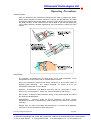
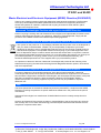
Ultrasound Technologies Ltd
Operating Manual
Fetatrack 310
Fetal Monitor
Ultrasound Technologies Ltd
Contents
About This Manual....................................................................................................................1
Safety In Use .............................................................................................................................2
Special Precautions........................................................................................................................ 2
Electrical Shock Hazard................................................................................................................. 2
Explosion Hazard............................................................................................................................ 2
Handling the Delicate Transducers.............................................................................................. 3
Symbols Used ................................................................................................................................. 3
Parts and Their Functions .......................................................................................................4
FT310 Front Panel Controls.......................................................................................................... 4
Recorder On/Off ...................................................................................................................... 4
Front Panel Event Mark.......................................................................................................... 4
Volume Up................................................................................................................................ 4
Volume Down........................................................................................................................... 4
US1 / US2 Transducer Select ............................................................................................... 4
Toco Zero ................................................................................................................................. 4
Indicators and Connectors ............................................................................................................ 5
’Power On’ Indication .............................................................................................................. 5
RS232 Output .......................................................................................................................... 5
Remote (Patient) Event Marker............................................................................................. 5
Probe Connection.................................................................................................................... 5
User Configuration.......................................................................................................................... 6
The Printer ....................................................................................................................................... 8
Ultrasound Fetal Monitoring .......................................................................................................... 9
Uterine Activity Monitoring........................................................................................................... 10
Fetal Activity .................................................................................................................................. 10
Alarms ............................................................................................................................................ 11
Transducer Belts........................................................................................................................... 12
Interpretation ................................................................................................................................. 12
Troubleshooting .....................................................................................................................13
No Display Information on LCD .................................................................................................. 13
Keyboard Does Not Respond ..................................................................................................... 13
No Sound From Loudspeakers................................................................................................... 13
No FHR Information on Display or Recorder............................................................................ 13
No Chart Printed ........................................................................................................................... 13
Maintenance ............................................................................................................................14
General........................................................................................................................................... 14
System Cabinet ..................................................................................................................... 14
Transducers ........................................................................................................................... 14
Specification ...........................................................................................................................15
Environmental.........................................................................................................................16
Electrommagnetic Compatibility ................................................................................................. 17
WEEE and RoHS.......................................................................................................................... 18
Ultrasound Technologies Position with regard to the WEEE Directive ................................ 18
Instructions for Disposal of Waste Equipment by Users in Private Households ................. 18
Instructions for Disposal of Waste Equipment by Commercial Users .................................. 18
RoHS .............................................................................................................................................. 18
©Ultrasound Technologies Ltd, Lodge Way, Portskewett, Caldicot, South Wales NP26 5PS, United Kingdom.
T +44 (0) 1291 425425
F: +44 (0) 1291 427093 E: [email protected] W: www.doppler.co.uk
Ultrasound Technologies Ltd
About This Manual
This booklet explains the operation and use of the FETATRACK 310 Antenatal
Cardiotocograph. Care has been taken during the design and manufacture of this product so
that it satisfies all of the current safety standards set down by BS EN60601-1-1990.
To achieve the best from this product read the following sections several times and if you
have any problems in the operation of a particular part of the product then contact your dealer
immediately or contact :
Ultrasound Technologies Ltd
Lodge Way
Portskewett
Caldicot, NP26 5PS
South Wales
UK
Tel
+44 (0) 1291 425425
Fax
+44 (0) 1291 427093
EMAIL [email protected]
A service manual containing circuit descriptions, diagrams, parts and spares lists is available
for the FETATRACK 310 by contacting the address above.
To maintain the FETATRACK 310’s performance it is recommended that it be included in a
periodic maintenance program. The user preventative maintenance program is covered in this
manual. Maintenance outside the scope of the user should be undertaken on an annual basis
by trained service personnel; full details are available from your supplier, service centre or
from Ultrasound Technologies Ltd.
The FETATRACK 310 is supplied complete with the following: FETATRACK 310 Single Fetus
Monitor
US1 Monitoring Transducer
External Toco Transducer
Patient Event Marker
Belt and Buckle set (x2)
Chart pack (x1)
Power Cord
Operating instructions
Coupling gel (0.25ltr)
Fetatrack310OpManualIssue6
FETATRACK 310 Twin Fetus
Monitor
US1 Monitoring Transducer
US2 Monitoring Transducer
External Toco Transducer
Patient Event Marker
Belt and Buckle set (x3)
Chart pack (x1)
Power Cord
Operating instructions
Coupling gel (0.25ltr)
Page 1
©Ultrasound Technologies Ltd, Lodge Way, Portskewett, Caldicot, South Wales NP26 5PS, United Kingdom.
T +44 (0) 1291 425425
F: +44 (0) 1291 427093 E: [email protected] W: www.doppler.co.uk
Ultrasound Technologies Ltd
Safety In Use
Special Precautions
Your FETATRACK 310 Antenatal Cardiotocograph has been
designed for electrical safety.
All the safety and operating
instructions should be read before operating the FETATRACK 310.
Failure to do so could result in injury to the user, patient, or damage
to the system and accessories.
Electrical Shock Hazard
Do not defeat the grounding integrity of this system. Protection
against electrical shock, in the event of failure of basic insulation, is
provided by the connection of the chassis to the safety ground.
Safety grounding occurs only when the 3-wire cable and plug
provided with the system are connected to a properly grounded
receptacle.
Do not remove the system cover. The system should be serviced by
trained and qualified personnel only. Contacting the hazardous
voltages within the system could cause serious injury.
Do not use the system if the power cord has any cuts or openings.
Do not use the transducer if the cable has any cuts or openings.
Do not use the transducer if the transducer face is cracked or
chipped.
Do not immerse the transducer cable connectors in any liquids.
Should the electrical safety fuses have to be replaced, use only fuses
of the same type and rating.
Explosion Hazard
Do not operate or use this system in the presence of flammable
anesthetics or gases as it could lead to explosion.
Fetatrack310OpManualIssue6
Page 2
©Ultrasound Technologies Ltd, Lodge Way, Portskewett, Caldicot, South Wales NP26 5PS, United Kingdom.
T +44 (0) 1291 425425
F: +44 (0) 1291 427093 E: [email protected] W: www.doppler.co.uk
Ultrasound Technologies Ltd
Safety In Use
Handling the Delicate Transducers
The transducers are delicate parts of the ultrasound system and
should be treated with care. The delicate crystals in the transducer
may crack and render the transducer unusable if the transducer is
subject to shock. Room temperature liquids should be used for
cleaning.
NEVER use alcohol or mineral oil as an acoustic coupling agent as
transducer face and cable damage will occur.
ONLY use approved ultrasound coupling gels.
Symbols Used
The following symbols are used on the FETATRACK 310 and are in
accordance with BS EN60601-1-1990.
Where they are associated with the connection of external
equipment, that equipment must meet the relevant safety standards
in all cases.
Alternating current
Associated with power on indicator
Type B Equipment
Unit classification
Off (power: disconnection from the mains)
On (power: connection to the mains)
Attention, consult accompanying documents.
Associated with auxiliary connections see
operating instructions.
This symbol on the product or on its packaging indicates that
this product must not be disposed of with your normal waste.
Fetatrack310OpManualIssue6
Page 3
©Ultrasound Technologies Ltd, Lodge Way, Portskewett, Caldicot, South Wales NP26 5PS, United Kingdom.
T +44 (0) 1291 425425
F: +44 (0) 1291 427093 E: [email protected] W: www.doppler.co.uk
Ultrasound Technologies Ltd
Parts and Their Functions
FETATRACK 310 Front Panel Controls
The front panel control area contains 6 buttons used to control the operation
of the unit, they are all indicated by icons to aid language variations.
Event Mark 1.
Places arrow in
upper portion of
chart
Volume Up
Volume Down
Toco Zero.
Sets Toco channel
to preset baseline
value.
Recorder On /
Off and speed
control
Select ultrasound channel
for audio output in twins
mode.
Recorder On/Off and Speed Change
This button is used to control the operation of the recorder. Press once and
the chart recorder will start, each consecutive short press will change the
speed . Pressing and holding the button down will stop the recording.
Event Mark 1
Places an event mark arrow at the top of the FHR scale .
Volume Up
This button is used to increase the audio volume level, or in configuration
mode to change user options.
Volume Down
This button is used to decrease the audio volume level, or in configuration
mode to change user operations.
US1 / US1 Transducer Select in Twins mode
Pressing this button changes the selected probe from US1 to US2 for volume
output. This is used when the unit is in twins mode with two US channels for
listening to either of the two fetuses. Press and hold to activate twins trace
offset.
Toco Zero
This button zeros the Toco trace to the selected baseline.
Fetatrack310OpManualIssue6
Page 4
©Ultrasound Technologies Ltd, Lodge Way, Portskewett, Caldicot, South Wales NP26 5PS, United Kingdom.
T +44 (0) 1291 425425
F: +44 (0) 1291 427093 E: [email protected] W: www.doppler.co.uk
Ultrasound Technologies Ltd
Parts and Their Functions
Inputs / Outputs and Displays
’Power On’ Indication
The green LED associated with the above symbol indicates that power is
connected to the apparatus when illuminated.
RS232 Output
This output is for the connection of an external computer for data transfer.
The maximum voltage that can be applied to this output is 15VDC.
WARNING:
Any external equipment connected to this output must meet the
equivalent MEDICAL safety standard to this product.
Connection must only be made by a qualified technician.
An isolation connection may be necessary when connection is
to be made to a personal computer.
Remote Event Marker
Connection of an external event mark switch allows the patient to indicate
events by printing an arrow in the gap between the FHR and UA traces. The
maximum voltage that can be applied to this output is 15VDC.
Probe Connections US1, US2, Toco
This is for the connection of approved Doppler and Toco transducers. The
maximum voltage that can be applied to this output is 15VDC.
Fetatrack310OpManualIssue6
Page 5
©Ultrasound Technologies Ltd, Lodge Way, Portskewett, Caldicot, South Wales NP26 5PS, United Kingdom.
T +44 (0) 1291 425425
F: +44 (0) 1291 427093 E: [email protected] W: www.doppler.co.uk
Ultrasound Technologies Ltd
Operating Procedures
Operating the FETATRACK 310
In this section, information is supplied which will help you use the FETATRACK 310 for the
fist time.
User Configuration
Firstly connect the AC supply cord.
It is necessary to set the operation of the FETATRACK 310 to meet your requirements.
Before turning the FETATRACK 310 on, press and hold down the Toco Zero button. Then,
whilst keeping the Toco Zero button pressed down, turn the FETATRACK 310 on by flicking
the AC input on/off switch which is located on the rear of the unit as part of the AC line input
will be illuminated.
socket. When the unit is on the front panel LED
The FETATRACK 310 starts and then enters its User Configuration Mode,
release the Toco Zero button as soon as ‘Calibrate System’ is displayed .
You are then prompted to enter the date if different to that displayed.
To change the day and month press the Volume Up button. One press advances
the day by one, pressing the Volume Up button for longer advances the day by
10.
To change the year press the Volume Down button. One press advances the
year by one, pressing the Volume Down button for longer advances the year by
10.
When the correct date is displayed press the Toco Zero button once.
You are then prompted to enter the time if different to that displayed.
This works in a similar manner to the date with the Volume Up button advancing
the hours and the Volume Down button advancing the minutes.
When the correct time is displayed press the Toco Zero button once.
You are then prompted to enter the Toco Base Line offset.
This sets an artificial zero line for the toco transducer above zero, it can be set
by pressing the Volume Up or Volume Down buttons for a value between 0 - 20.
After setting this value the Toco will be set to this every time the Toco Zero
switch is pressed, and allows small negative Toco excursions to be seen on the
chart.
When the chosen zero offset is displayed press the Toco Zero button once.
Fetatrack310OpManualIssue6
Page 6
©Ultrasound Technologies Ltd, Lodge Way, Portskewett, Caldicot, South Wales NP26 5PS, United Kingdom.
T +44 (0) 1291 425425
F: +44 (0) 1291 427093 E: [email protected] W: www.doppler.co.uk
Ultrasound Technologies Ltd
Operating Procedures
You are then prompted to enter the Toco Filter Value.
This sets the filtering within the monitor to produce a smoother Toco trace if
required. ( The filter can remove some of the maternal breathing artifact). It is set
by pressing the Volume Up button for a value soothing value between 1sec and
2sec..
When the correct filter value is displayed press the Toco Zero button once.
You are then prompted to enter the Toco Range.
This sets the response of the Toco transducer to either a full scale of 100 or 200
on the chart print out. It is set by pressing the Volume Up button for a value
between 100 and 200..
When the correct range is displayed press the Toco Zero button once.
You are then prompted to enter the Chart recorder speed.
This sets the initial turn-on speed of the chart recorder. Then once the chart is
running the speed can be further changed to 1 ,2 or 3 cm/min. It is set by
pressing the Volume Up button for a value of 1, 2 or 3 cm/min..
When the correct speed is displayed press the Toco Zero button once.
You are then prompted to select the Data Block on or off.
The Data Block is printed at the start of each recording, this function can be
disabled by setting Data Block to off. It changes from on to off and back again by
pressing the Volume Up button..
When the Data Block is set to your requirements press the Toco Zero button
once.
You are then prompted to select the Tachycardia Alarm on or off.
The Tachycardia Alarm is triggered when the system detects a Tachycardia
above a preset value that the user can choose. The Alarm can be a level alarm
or one calculated from a complex. Press the Volume Up button to change the
setting. The alarm is tone is silenced by pressing the units Volume button.
When the Tachycardia Alarm is set to your requirements press the Toco Zero
button once.
You are then prompted to select the Bardycardia Alarm on or off.
The Bradycardia Alarm is triggered when the system detects a Bradycardia
below a preset value that the user can choose. The Alarm can be a level alarm
or one calculated from a complex. Press the Volume Up button to change the
setting. The alarm is tone is silenced by pressing the units Volume button.
When the Bradycardia Alarm is set to your requirements press the Toco Zero
button once.
The FETATRACK 310 will then restart and operate according to your settings.
The FETATRACK 310 is now operational, and the LCD screen will show US1 --- us2 -(if the unit is only a single fetus monitor it will only display US1 ---) and a Toco value.
Fetatrack310OpManualIssue6
Page 7
©Ultrasound Technologies Ltd, Lodge Way, Portskewett, Caldicot, South Wales NP26 5PS, United Kingdom.
T +44 (0) 1291 425425
F: +44 (0) 1291 427093 E: [email protected] W: www.doppler.co.uk
Ultrasound Technologies Ltd
Operating Procedures
The Printer
The FETATRACK 310 prints on preprinted z-fold thermal paper using a thermal
array print head. Fetal heart rate, uterine activity, and fetal movement are
recorded together with date, time, recorder speed, operating mode and alarm status.
The printer also prints a header block each time the printer is turned on, that contains
Time and Date, Patient Name, Gestational Age, Patient or Bed Number, Hospital or
Doctor along with a print viability test bar that prints to all dots of the printhead.
To load the printer with paper, open the printer door by pulling the recorder door
using the opening provided on the printer. It will then release and opens downwards
exposing the printer paper tray. Remove the new paper pack from its protective
plastic cover and insert the pack into the recorder so that the printed side of the paper
is uppermost and the FHR trace is on the left.
Pull the paper out of the front of the unit making sure it is positioned parallel to the
roller and the close the door. The pack will self align when the recorder is run.
To operate the printer press the Recorder On/Off button. The printer will start to run
and the chart speed will be shown in the LCD display. To turn the printer off press
and hold the Recorder On/Off button until the printer stops. (This only operates after
the data block has been printed). A small amount of paper will be fed out at high
speed.
The printer will record at 1, 2 or 3 cm/min. To change the speed during recording
simply press the Recorder On/Off button momentarily. The FETATRACK 310 can
be run at the speed of your choice, and will always start at this pre-programmed
speed every time the printer is turned on. For details of how to change the preprogrammed speed refer to ‘User Configuration’.
When the paper pack runs out the Fetatrack 310 will sound a short alarm and display
“Paper ?”. For the next 30 min the system will store HR1 , HR2 and Toco until either
the store becomes full, the user presses and holds the Recorder On/Off button to
reset the store and loose the stored data or the user inserts a new paper pack,
presses Recorder On/Off button once and the Fetatrack 310 prints the stored data
and returns to normal printing.
When the store reaches 90% full the Fetatrack 310 will “Alarm” and show “StoreLow”,
if the store then becomes full the display changes to “StoreFull” and there will be no
further storage. The data can still be printed by pressing Recorder On/Off button
once or reset by pressing and holding the Recorder On/Off button.
The print from store is lighter than the normal trace to distinguish stored data.
Fetatrack310OpManualIssue6
Page 8
©Ultrasound Technologies Ltd, Lodge Way, Portskewett, Caldicot, South Wales NP26 5PS, United Kingdom.
T +44 (0) 1291 425425
F: +44 (0) 1291 427093 E: [email protected] W: www.doppler.co.uk
Ultrasound Technologies Ltd
Operating Procedures
Ultrasound Fetal Monitoring
The FETATRACK 310 ultrasound transducer is used to detect and monitor the fetal
heart beat. The FETATRACK 310 can monitor twins and if this option is chosen it is
supplied with two Ultrasound transducers. The primary Ultrasound Transducer
(always supplied ) has a yellow coded plug while the twin channel has a blue coded
plug. Push the relevant plug firmly into is colour coded front panel US socket and
turn the unit on.
Locate a clear fetal heart sound using a Doppler Fetal Heart Detector and secure
the stretch belt in position, so that it passes over the transducer site, and clamp in
place by fastening the buckle after feeding the belt through the transducer.
Apply gel to the surface of the transducer locating it approximately in the position
determined by the Doppler detector. Position the transducer to obtain the clearest
fetal heart sound. The heart rate processor will start to calculate heart rate within
a few seconds and the heart rate can be observed on the LCD display. Correct
operation can be verified by observing that the pulse lamp is flashing at the heart
rate.
The heart shaped fetal pulse indicator is also used as a signal quality indicator.
When positioning the transducer observe the indicator, which should be solid under
the best signal conditions. If this indicator is only showing an outline heart then this
is an indication that the signal quality is not optimum. Improved recordings can
be obtained by repositioning the transducer so that this indicator always shows a
solid heart. In the absence of signals of adequate quality this indicator will be
permanently off.
The audio volume can be increased by pressing the volume up button marked with
the up arrow. Conversely to decrease audio volume press the button marked with
the down arrow. In twins mode the audio output is selected for either channel by
pressing the US 1/2 button. The selected channel is indicated on the LCD display by
the capital US letters. Once a clear fetal heart signal has been located set the
volume to the desired level using these controls.
Transducer position should be checked at least half-hourly during labour-monitoring
or prolonged NST. When repositioning the transducer, further coupling gel may
be required When repositioning the transducers always ensure that the fetal pulse
indicates the optimum signal conditions.
Results will vary from one patient to another, but in all cases good transducer
positioning is essential, and this may be aided by the use of a liberal amount of
coupling gel.
With the fetus in the vertex presentation, and the mother sitting or supine, the
clearest sound will normally be found on the midline below the umbilicus. In the
lateral position, clearer sounds may be found with the transducer displaced from the
centre line to the upper surface of the abdomen. The clearest signals in breach
presentation may be located higher and to one side.
Fetatrack310OpManualIssue6
Page 9
©Ultrasound Technologies Ltd, Lodge Way, Portskewett, Caldicot, South Wales NP26 5PS, United Kingdom.
T +44 (0) 1291 425425
F: +44 (0) 1291 427093 E: [email protected] W: www.doppler.co.uk
Ultrasound Technologies Ltd
Operating Procedures
Transducer position which results in sounds with a strong placental or cord
signal should be avoided, as these frequently render traces with artifacts.
It is important that a distinct fetal heart sound is present during monitoring for
correct function of the unit . Any doubt about fetal variability should be checked by
listening to the audible signal, or by an alternative diagnostic technique.
A simple check of the ultrasonic system can be made by holding the transducer
against the palm of the hand and stroking the back of the hand at a fixed rate, for
example, twice per second. A clear audible signal should be heard and the digital
display should show a rate after approximately five seconds. With the printer
running this rate will be recorded on the chart.
In the event of HR1 and HR2 traces overlapping or having similar rates the HR2
(US2) trace can be offset by –20bpm by pressing and holding the US½ key. This is
reset when the recording session finishes.
Uterine Activity Monitoring
The Toco transducer is used to monitor uterine activity. The transducer plug is
colour coded grey for ease of identification. To monitor uterine activity plug the
Toco transducer into the grey UA input socket.
The Toco transducer is sealed to prevent the ingress of fluids. NO coupling gel is
required for this transducer to operate correctly.
Place the transducer on the centre line over the fundus in a position where the
uterus is firm, and secure in place with the stretch belting. Attach belt in the same
fashion as with the ultrasound transducer.
Once the transducer is in position, push the Toco Zero button on the front panel to
zero the recording. The position of the zero baseline can be set to suit individual
preferences. For details of how to change the pre-programmed baseline refer to
‘User Configuration’.
Fetal Activity
Fetal activity may be recorded with the assistance of the patient. A hand-held
marker switch is provided for this purpose and this is plugged into the socket
immediately to the right of the UA input on the front of the unit.
If the patient feels movement of the fetus she may press the switch and this will
mark the paper with an arrow in the gap between the HR and UA traces.
Alternatively this marker may be used by the midwife to indicate any changes made
during the procedure, such as repositioning of the transducers or movement of the
patient.
A front panel event marker is also provided, and this marks the trace on the top edge
of the HR scale. This can be used where two types of indication are required.
Fetatrack310OpManualIssue6
Page 10
©Ultrasound Technologies Ltd, Lodge Way, Portskewett, Caldicot, South Wales NP26 5PS, United Kingdom.
T +44 (0) 1291 425425
F: +44 (0) 1291 427093 E: [email protected] W: www.doppler.co.uk
Ultrasound Technologies Ltd
Operating Procedures
Alarms:
The Fetatrack 310 has built in Bradycardia and Tachycardia alarms. These can be
set On or Off in the setup program. The status of the alarms are printed in the center
of trace between the UA and FHR traces. When an alarm is activated a down arrow
with an “A” is printed at the top of the trace and an audio alarm sounds. Pressing
either volume up or down can reset the alarm.
When set to “Level” the Fetatrack 310 monitors the average of the last 30 sec of
Heart Rate data and alarms if this falls below the selected numeric value.
When set to “Complex” the Fetatrack 310 monitors the last 3 time periods of 20 sec
each of Heart Rate data and alarms if the fall below the selected numeric value and
are in a descending rate for Bradycardia or ascending for Tachycardia.
Paper Out will sound a short alarm to draw attention to the monitor, if the paper out
store reaches 90% full the Alarm will sound again until cancelled by the user pressing
either volume up or volume down.
Fetatrack310OpManualIssue6
Page 11
©Ultrasound Technologies Ltd, Lodge Way, Portskewett, Caldicot, South Wales NP26 5PS, United Kingdom.
T +44 (0) 1291 425425
F: +44 (0) 1291 427093 E: [email protected] W: www.doppler.co.uk
Ultrasound Technologies Ltd
Operating Procedures
Transducer Belts
Both the ultrasound and contractions transducers are held in position with elastic
belting which maintains the active elements in contact with the abdomen. The belts
should first be placed around the patient and held in place at the correct tension with
the plastic buckles. As the transducers are free to slide on the belt final positioning
can be easily achieved. Similarly repositioning of the transducers is made very much
simpler.
Interpretation
The following is intended only as a brief guide. For a fuller explanation of the
interpretation of chart records, refer to suitable reference books.
During the antepartum period the Non Stress Test (NST) is an accurate means of
predicting fetal well-being. The criteria proposed by Schifrin et al for the
interpretation of the NST is summarised.
Reactive - accelerations of 15 BPM or more which last for 15 seconds or longer
twice in any 10 minute period. These may be accompanied by fetal activity.
Non-reactive - evidence of fetal movement during a forty minute period, but without
the reactivity indicated above.
Unsatisfactory - recording quality too poor to determine the above criteria.
Stimulation of the fetus, or repositioning of the transducers may result in an improved
recording.
Results from the NST may indicate the requirements to perform other diagnostic
checks such as the Contractions Stress Test (CST).
Fetatrack310OpManualIssue6
Page 12
©Ultrasound Technologies Ltd, Lodge Way, Portskewett, Caldicot, South Wales NP26 5PS, United Kingdom.
T +44 (0) 1291 425425
F: +44 (0) 1291 427093 E: [email protected] W: www.doppler.co.uk
Ultrasound Technologies Ltd
Troubleshooting
The information in this section will help you to check and correct common operation and
system problems. Refer to the troubleshooting hints which deal with your problem. Perform
the suggested steps. If the problem is not solved, check once again to make sure that you
have used all of the suggested steps to resolve the problem.
Electronic failures and service procedures are not included in this manual, as all servicing of
the system must be performed by a qualified service technician. Valuable time however can
be saved by documenting the problem .
In general, when you have a problem, check your control settings to be sure that they are in
proper operating position. Consult the appropriate section in this manual for specific
information on particular controls or operating modes.
WARNING:
Disconnect system from the power source before checking fuses and
connections.
Check all connections and fuses. Replace fuses with same type and rating as indicated on
the rear panel of the unit.
No display information on LCD
Verify the system is on and that the fuses are intact.:
·
Keyboard does not respond
·
·
Reset system by turning off then back on.
Verify the system is on and that the fuses are intact.
No sound from loudspeaker.
·
·
·
·
Verify the system is on and that the fuses are intact.
Check volume control is set high.
Check that the correct transducer has been selected.
Check connection of the transducer.
No FHR information on display or FH trace printed on recorder.
·
·
·
Check that the correct transducer has been selected and connected
to the patient.
Check connection of the transducer.
Check for audio FH complex and reposition transducer until clearly
heard.
No chart printed .
·
·
·
·
·
Verify the system is on and that the fuses are intact.
Check that the recorder is turned on.
Check paper is inserted into the recorder correctly.
Check recorder door is correctly closed
Check that paper moves out of the recorder at the correct rate.
Fetatrack310OpManualIssue6
Page 13
©Ultrasound Technologies Ltd, Lodge Way, Portskewett, Caldicot, South Wales NP26 5PS, United Kingdom.
T +44 (0) 1291 425425
F: +44 (0) 1291 427093 E: [email protected] W: www.doppler.co.uk
Ultrasound Technologies Ltd
Maintenance
The following are the user preventative maintenance tasks. It is recommended that these be
performed on a regular basis at a frequency determined by the usage of the equipment, but
not less than once every month.
WARNING:
Before undertaking any of these tasks disconnect the unit from the
mains.
General
Check all cables, connectors and transducers for damage and repair
or replace where necessary. The repair may involve your local
service centre, supplier or Ultrasound Technologies Ltd. For advise
on any damaged part contact them immediately.
Cleaning - Enclosure
Clean the exterior of the system with a soft dry cloth. In the event of
stubborn spots, disconnect the system from the power source. Use a
soft cloth that has been dampened - not soaked - in a mild detergent
solution or isopropyl alcohol. Be sure to keep excess moisture from
entering the cabinet via any openings that may be present.
Cleaning - Transducers
Use a cloth dampened in a mild detergent solution or isopropyl
alcohol to clean the transducer and cable. Remove all traces of the
detergent or alcohol by wiping with a cloth dampened in clear water.
Never soak the transducer cable or connector.
WARNING:
Transducers must never be exposed to gas or heat sterilization or be
left immersed in any liquid for more that a few seconds.
Fetatrack310OpManualIssue6
Page 14
©Ultrasound Technologies Ltd, Lodge Way, Portskewett, Caldicot, South Wales NP26 5PS, United Kingdom.
T +44 (0) 1291 425425
F: +44 (0) 1291 427093 E: [email protected] W: www.doppler.co.uk
Ultrasound Technologies Ltd
Specification
Ultrasound
Frequency
Transducer
Audio Response
Range
Power Output
Signal Processing
Indicators
1.5 or 2.1 and 1.8 MHz continuous wave
Multi element wide angle
300 - 1 KHz
50 - 210 bpm
5 mW/sq cm max. SATA
Software AUTOCORRELATOR
LCD heart rate and pulse indication
Transducer
Response
Scale
Indicators
Differential external pressure transducer
0 - 5 Hz
0 - 100
LCD Toco numeric level indication
Toco
Event Mark
Hand held
Unit Front Panel
User operated
User operated
Bradycardia
Tachycardia
Paper Out
Complex and Level alarms
Complex and Level alarms
Short Alarm
Alarms
Data Presentation
Strip chart recorder and alphanumeric display module.
Printhead
Resolution
Speeds
Speed accuracy
Paper
Paper type
Paper out storage
4 inch thermal solid state printhead
8 dots / mm
1,2,3,cm/min
Better than 1%
Z fold
Black thermal
30 mins
Display
Controls
32 character by 2 line LCD display module
6 control buttons (for Paper Start /Stop,
Volume Up, Volume Down, US½, Toco
Zero and Event Mark)
Green power on/ off
Indicators
Fetatrack310OpManualIssue6
Page 15
©Ultrasound Technologies Ltd, Lodge Way, Portskewett, Caldicot, South Wales NP26 5PS, United Kingdom.
T +44 (0) 1291 425425
F: +44 (0) 1291 427093 E: [email protected] W: www.doppler.co.uk
Ultrasound Technologies Ltd
Specification
Power Supply
AC input voltage
Frequency
Power
200 - 260 VAC or 100 - 130 VAC (User
selected)
46 - 64 Hz
60VA
Enclosure
Material
0
Aluminum
Environmental
Working temperature
+10°C to +40°C
Relative humidity
30% to 75%
Storage/Transport temperature -10°C to +70°C
Safety
Unit
Electrical Designation
Designed to BS EN60601-1-1990.
Class 1 Type B
Computer interface
Transfer
Data Rate
Data Standard
Data Format
3 wire RS232
9600 baud
8 bits no parity 1 stop bit
UltraTec Comms Standard
The following Consumables are available for use with the FETATRACK 310
Belt / Buckle set (10 belts / 2 Buckles per pack)
Chart pack (10 per pack))
Power Cord
Coupling gel (0.25ltr) (12 per box)
This Equipment complies with the essential requirements of the European Council Directive.
93/42/EEC
0120
Fetatrack310OpManualIssue6
Page 16
©Ultrasound Technologies Ltd, Lodge Way, Portskewett, Caldicot, South Wales NP26 5PS, United Kingdom.
T +44 (0) 1291 425425
F: +44 (0) 1291 427093 E: [email protected] W: www.doppler.co.uk
Ultrasound Technologies Ltd
Electromagnetic Compatibility
Guidelines for Identifying and resolving adverse EMC conditions
Emissions
Care has been taken through the design and manufacturing processes to minimise
the EM emissions that may be produced by this equipment. However, in the unlikely
event that the unit causes an EM disturbance to adjacent equipment, we suggest that
the procedure is carried out 'out of range' of the affected equipment.
Immunity
If the user has any doubt regarding the unit's EM immunity during routine operation,
we suggest that the source of EM disturbance is identified and its emissions reduced.
If the user has any doubt regarding the identification and resolution of adverse EM
conditions, they may contact Ultrasound Technologies Ltd to seek advice
EMC Testing
During conformity testing the Fetatrack 310 was subjected to International Standard
EMC tests. During the majority of these tests no non conformances were observed.
During EN60601-1-1:2001 testing the FetaTrack 310 was shown to be susceptible to
the following tests.
Effect was a displayed rate of 115 to
125 bpm at each harmonic and sub
Conductive
Test applied a 3Vrms RF magnetic harmonic of the transducer frequency.
disturbance induced field to transducer cables with a 2Hz No disturbance was detected at other
by applied RF field modulation.
frequencies
Radiated RF
Effect was a disturbance to the UA
transducer causing a static UA
Test applied: 3V/m 80Mz to 2.5GHz reading of up to 9 units
Applied test signal is very high for high
sensitivity electronics and non applied
transducers. With correctly applied
transducers interference from in band
RF signals is unlikely.
Normal operation is unaffected and the
static reading can be cancelled by
pressing the toco zero button
Normal mains power is unlikely to cause
such a transient / burst. Displayed rate is
Electrical fast
Test applied: +/-2KV AC power, +/- Effect was a FHR reading of 198 BPM unlikely to occur when transducers are
transients and bursts 1KV Signal Cables
.
connected to a patient.
Electro Static
Discharge
Test applied: +/-2KV, +/-4Kv,
+/8KV Air Discharge, +/-2KV, +/4KV, +/-6KV Contact Discharge.
Repetition Rate 1second
Effect was a FHR reading of 58 BPM
Unit should be used in a low static
environment. Displayed rate is unlikely
to occur when transducers are
. connected to a patient.
Surge
Test applied: +/-0.5KV, +/-1KV, +/2KV AC power line to ground, +/0.5KV, +/-1KV, +/-6KV AC power
line to line
Effect was a FHR reading of 58 BPM
Normal mains power is unlikely to cause
such a surge. Displayed rate is unlikely
to occur when transducers are
. connected to a patient.
Fetatrack310OpManualIssue6
Page 17
©Ultrasound Technologies Ltd, Lodge Way, Portskewett, Caldicot, South Wales NP26 5PS, United Kingdom.
T +44 (0) 1291 425425
F: +44 (0) 1291 427093 E: [email protected] W: www.doppler.co.uk
Ultrasound Technologies Ltd
WEEE and RoHS
Waste Electrical and Electronic Equipment (WEEE) Directive (2002/96/EC)
There is an increasing interest in the proper disposal of used electronic equipment. The European
Union (EU) has developed the WEEE (Waste Electrical and Electronic Equipment) Directive to
ensure that systems for collection, treatment and recycling of electronic waste will be in place
throughout the European Union.
1
Ultrasound Technologies Position with regard to the WEEE Directive
Product recycling is nothing new and Ultrasound Technologies have implemented processes in each
member state where the company has a presence. Ultrasound Technologies will comply with the
provisions of the WEEE Directive and national implementing legislation.
2
Instructions for Disposal of Waste Equipment by Users in Private Households
This symbol on the product or on its packaging indicates that this product must not be disposed of
with your other household waste. Instead, it is your responsibility to dispose of your waste
equipment by handing it over to a designated collection point for the recycling of waste electrical
and electronic equipment. The separate collection and recycling of your waste equipment at the
time of disposal will help to conserve natural resources and ensure that it is recycled in a manner
that protects human health and the environment. For more information about where you can drop off
your waste equipment for recycling, please contact your local waste disposal authority, your
household waste disposal service or the supplier where you purchased the product.
As a producer of electronic devices, Ultrasound Technologies will provide for the financing of the
treatment and recycling of waste returned through these designated collection points in accordance
with local requirements.
3
Instructions for Disposal of Waste Equipment by Commercial Users
For users of Ultrasound Technologies equipment, other than private households, Ultrasound
Technologies will provide free recycling of equivalent medical electronic equipment once a customer
has returned the equipment to Ultrasound Technologies, with all transport and importation costs paid,
and where a replacement product is being supplied by Ultrasound Technologies. Where a
replacement product is not being supplied, recycling services may be provided on request at
additional cost.
RoHS
The RoHS (Restriction of Hazardous Substances) directive (2002/95/EC), compliments the WEEE
Directive by banning the presence of specific hazardous substances in the products at the point of
manufacture.
Ultrasound Technologies is a manufacturer of Medical Devices and is currently exempt from this
directive.
However at Ultrasound Technologies we take our responsibilities to the environment very seriously
and currently 99% of our entire manufacturing process and parts meet the RoHS directive and full
compliance is expected within 2007.
Fetatrack310OpManualIssue6
Page 18
©Ultrasound Technologies Ltd, Lodge Way, Portskewett, Caldicot, South Wales NP26 5PS, United Kingdom.
T +44 (0) 1291 425425
F: +44 (0) 1291 427093 E: [email protected] W: www.doppler.co.uk