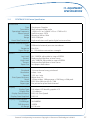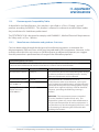
1
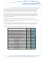
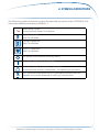
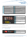
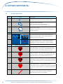
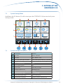
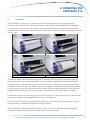
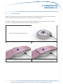
®
fetaTRACK
310
fetal monitoring system
Operating Manual
Issue 1.02
CONTENTS
1. ABOUT THIS MANUAL
2. ABOUT THE FETATRACK®310
3. SAFETY
4. SYMBOL DEFINITIONS
5. CONTROLS AND INDICATORS
5.1 Identification
5.2
Transducer Display
5.3
Printer Status Display
5
6
7
8
8
9
9
6. SOFT KEY FUNCTIONS (fn)
10
10
11
11
7. SETTING UP THE FETATRACK®310
12
12
13
13
14
14
8. OPERATING THE FETATRACK®310
15
15
16
17
18
18
19
19
19
20
21
21
21
21
22
22
22
23
23
23
23
24
6.1
6.2
6.3
Soft Key Menu Icons
Operating the Soft Key Menu
Alarm Status Menu
7.1
Electrical Connection
7.2
System Settings Menu
7.3
System Settings Descriptions
7.4Navigation
7.5
Exiting ‘System Settings’ mode
8.1
The Printer
8.2
Paper Out
8.3
Transducer Belts
8.4
Fetal Heart Rate Monitoring
8.4.1Ultrasound
8.4.2
Signal Quality
8.4.3
Audio Signal
8.4.4
General Guidance
8.4.5 Alarms
8.5
Uterine Activity Monitoring
8.5.1
External Uterine Pressure 8.5.2
Intrauterine Pressure
8.5.2.1 Contra-indications
8.5.2.2 Catheter Insertion
8.5.2.3 Preparation of IUP Transducer
8.5.2.4 Proceed with Monitoring
8.6
Direct Fetal ECG (FECG)
8.6.1
Contra-indications
8.6.2
Leg Lead Preparation
8.6.3
Leg Lead Connection
8.6.4
Fetal ECG Electrode Application
2
4
Fetatrack®310 Operating Instructions Copyright © Ultrasound Technologies Ltd 2012
8.6.5
8.7
Electrode to Leg Lead Connections
Fetal Activity Monitoring
24
24
9. PREVENTATIVE MAINTENANCE
25
25
10. TROUBLESHOOTING
26
26
26
11. EQUIPMENT SPECIFICATION
27
27
28
29
29
30
31
12. WARRANTY
32
32
34
34
13. WEEE and RoHS
35
9.1
10.1
10.2
11.1
11.2
11.3
11.3.1
11.3.2
11.3.3
12.1
12.2
12.3
Cleaning
Functional Checks
Operational Checks
FETATRACK®310 Device Specification
Environmental Requirements
Electromagnetic Compatibility Tables
Manufacturers declaration and guidance : Emissions Manufacturers declaration and guidance : Immunity
Manufacturers declaration and guidance: Separation Distances
Terms and Conditions
The Ultrasound Technologies CUSTOMER CARE PROMISE
Meeting Expectations
Fetatrack®310 Operating Instructions Copyright © Ultrasound Technologies Ltd 2012
3
1. ABOUT THIS MANUAL
This user manual provides instructions for the operation of the FETATRACK®310
Cardiotocograph, hereafter referred to as FETATRACK®310.
It is recommended that personnel study this manual before attempting to operate the
FETATRACK®310 device. The safe and effective use of this equipment requires understanding
of, and compliance with, all warnings, cautionary notices, and instructions marked on the
product, and included in this manual.
Typical users of FETATRACK®310 are trained medical professionals including, but not limited
to, midwives, clinicians and other health professionals.
If you have any queries regarding the operation of the FETATRACK®310 or understanding the
information provided in this manual please contact:
Ultrasound Technologies Ltd
Lodge Way
Portskewett
Caldicot, NP26 5PS
South Wales, United Kingdom
Tel
+44 (0) 1291 425425
Fax +44 (0) 1291 427093
[email protected]
4
Fetatrack®310 Operating Instructions Copyright © Ultrasound Technologies Ltd 2012
2. ABOUT THE FETATRACK®310
The FETATRACK®310 Cardiotocograph is a fetal monitor designed to provide cost effective
care throughout pregnancy. The FETATRACK®310 can be configured as an Antepartum or
Intrapartum monitor for use in maternity wards, antenatal clinics or doctor’s surgeries.
The FETATRACK®310 can monitor fetal heart rates, using low power ultrasound or fetal ECG,
external uterine pressure using an external tocodynamometer, and intrauterine pressure.
Measurements are displayed on a large graphic LCD, while the data is recorded on a highresolution thermal printer.
Fetal heart rates are monitored using Doppler ultrasound transducers. Up to three
ultrasound transducers can be connected to a single FETATRACK®310 (Elite only), to track the
heart rates of twins or triplets.
The FETATRACK®310 has bradycardia and tachycardia alarm functionality, memory backup
and an output socket for remote display of screen information on a compatible system.
The FETATRACK®310 is supplied with the following accessories for each version:
310 basic
310 elite
Wide Angle Ultrasound Transducer - US1
1
1
Wide Angle Ultrasound Transducer - US2
Optional
Optional
Wide Angle Ultrasound Transducer - US3
No
Optional
External Uterine Pressure Transducer - TOCO
1
1
Fetal Electrocardiogram Module - FECG
No
Optional
Intrauterine Pressure Module - IUP
No
Optional
Event Marker
1
1
Input Sockets
3
6
Elastic Belt
2
2/3/4
Chart Paper
1
1
Ultrasound Coupling Gel 0.25L
1
1
AC line Cord
1
1
Operating Manual
1
1
Fetatrack®310 Operating Instructions Copyright © Ultrasound Technologies Ltd 2012
5
3. SAFETY
The FETATRACK®310 is designed to comply with EN60601-1 Class 1, with protective earth via
the AC line cord.
The FETATRACK®310 must be used with an appropriately rated and approved cord-set in
accordance with the regulations of the country it is used in.
When positioning the unit, ensure that access is available to the mains On/Off switch and
power cable located on the rear of the unit.
Should the electrical safety fuses have to be replaced, use only fuses of the type and rating
defined on the rear label of the unit and in the Device Specification.
If in doubt about the correct operation of the FETATRACK®310, fetal condition must be
checked immediately by an alternative method.
Fluids should not be allowed to enter the device as this may result in damage to the system.
We would recommend that, to maintain the standard of performance of the FETATRACK®310,
whenever possible, the monitor is included in a scheduled maintenance scheme.
Only qualified personnel should service the device and the unit cabinet should not
be opened except by these personnel due to the risk of hazardous electrical shock. All
service requirements should be referred to an Ultrasound Technologies Ltd. authorised
representative.
WARNING: The FETATRACK®310 must not be used in the presence of flammable anaesthetics
or oxygen rich environments.
WARNING: US Federal Law restricts this device for sale on or by order of a physician.
6
Fetatrack®310 Operating Instructions Copyright © Ultrasound Technologies Ltd 2012
4. SYMBOL DEFINITIONS
The following symbols have been used on the front and rear panels of the FETATRACK®310
and are here defined according to EN60101-1.
Alternating Current
Associated with Power On Indicator
Type B Equipment
Unit Classification
Type BF Equipment
Unit Classification
Type CF Equipment
Unit Classification
Off (power: disconnection from the mains)
On (power: connection to the mains)
!
Attention, consult accompanying documents.
Associated with auxiliary connections, see operating instructions.
This symbol on the product or on its packaging indicates that this
product must not be disposed of with your normal waste.
Fetatrack®310 Operating Instructions Copyright © Ultrasound Technologies Ltd 2012
7
5. CONTROLS AND
INDICATORS
5.1Identification
8
9
10
11
1
2
3
12
4
5
6
7
14
13
15
18
16
8
17
Fetatrack®310 Operating Instructions Copyright © Ultrasound Technologies Ltd 2012
5. CONTROLS AND
INDICATORS
1
Power On indicator
10
Transducer Display
2
Activate the second function (fn) menu
11
Printer Status Display
3
Printer On/Off and speed control
12
Transducer connections 1,2,3
4
Ultrasound volume increase
13
Printer Door (pull to open)
5
Audio Selector for Ultrasound channels
14
Transducer connections 4,5,6 (310 Elite only)
6
Ultrasound volume decrease
15
Fuse Drawer and voltage selector
7
Set Uterine Pressure to zero (UA0)
16
Mains on/off switch
8
Date and Time display
17
Mains AC supply connector
9
Transducer connections display
18
Device serial number
5.2
Transducer Display
19
Focus Icon - Indicates active audio
channel
20
Fetal Pulse Indicator
21
Transducer Identification
22
Fetal Heart Rate
Colour coded to match associated
transducer
23
Uterine Activity Reading
The layout of the Ultrasound and ECG transducer display will adjust dependant on how
many transducers are connected. This is to provide the clearest display of all the readings of
connected transducers.
The Uterine Activity readings remain in the same location on the display regardless of which
other transducers are connected.
5.3
Printer Status Display
24
Paper Out Indicator
25
Printer Speed Indication
Fetatrack®310 Operating Instructions Copyright © Ultrasound Technologies Ltd 2012
9
6. SOFT KEY FUNCTIONS (fn)
6.1
Soft Key Menu Icons
Key
Icon
Function
2
Exit soft key menu or return to previous menu.
3
Operator event indicator:
Prints an event mark on the paper.
Mark appears on top edge of FHR scale.
7
Alarm status menu:
Displays the current alarm status and give access
to alarm options.
F310 Elite Only
4
Switches the display between trace mode and
numeric display mode. The target mode will
appear as the soft key icon.
5
Switches between split trace mode or combined
(normal) mode printing. Only available when
graticule printing is enabled in system settings.
Alarm Status Menu
4
Low FHR Alarm. This indicates that the Low FHR
alarm is enabled. Press the associated key on the
control panel (4) to disable/enable this alarm.
5
High FHR Alarm. This indicates that the High FHR
alarm is enabled. Press the associated key on the
control panel (5) to disable/enable this alarm.
6
Bradycardia Alarm. This indicates that the
Bradycardia alarm is enabled. Press the associated
key on the control panel (6) to disable/enable this
alarm.
7
Tachycardia Alarm. This indicates that the
Tachycardia alarm is enabled. Press the associated
key on the control panel (7) to disable/enable this
alarm.
This line is drawn across an alarm symbol to
indicate that the alarm is disabled.
10
Fetatrack®310 Operating Instructions Copyright © Ultrasound Technologies Ltd 2012
6. SOFT KEY FUNCTIONS (fn)
6.2
Operating the Soft Key Menu
The soft key menu will appear when the ‘fn’ key (2) is pressed during normal operating mode.
The menu will appear at the bottom of the display and will disappear again after 10 seconds
if no further keys are pressed.
When the soft key menu is visible the control panel keys do not carry out the functions
marked on them. Instead the keys will activate the functions shown on the display directly
above the keys. The table above gives a brief description of the functions of the soft keys
which may appear. Not all the controls will appear on the FETATRACK®310 Basic and these
soft keys will have no effect.
6.3
Alarm Status Menu
The Alarm Status menu displays the current state of the alarm system. Only alarms that are
enabled in the System Settings menu will appear in this menu.
Alarms can be enabled or disabled by pressing the associated soft key when the menu is
visible. A line will be drawn through an alarm that is disabled, and the line removed for an
alarm that is enabled.
Further alarm settings are accessed through the System Settings, see “SETTING UP THE
FETATRACK®310”.
Fetatrack®310 Operating Instructions Copyright © Ultrasound Technologies Ltd 2012
11
7. SETTING UP THE
FETATRACK®310
7.1
Electrical Connection
The FETATRACK®310 will operate with a mains input voltage between 100 and 260 volts AC,
50 or 60 Hz. Ensure that the correct voltage is selected before connecting the unit to the
mains supply.
The FETATRACK®310 is fitted with a dual-range mains power supply, which can be changed
externally to suit the local AC line voltage. The currently selected voltage is displayed in the
window of the fuse drawer (15), located on the rear of the unit.
To select a different voltage, ensure the unit is switched off and the AC power cord is not
connected. Open the fuse door (15) using a small flat blade screwdriver and remove the fuse
tray using the screwdriver. Turn over the fuse tray 180˚ and re-insert in the fuse drawer. The
new voltage should now be visible through the window of the fuse door once it has been
closed.
Connect the AC supply cord and switch on the FETATRACK®310. The AC input on/off switch
(16) is located on the rear of the unit adjacent to the AC line input socket (17). Observe that
the front panel power on indicator (1) is illuminated when the unit is switched on.
The FETATRACK®310 is now operational and the display will indicate the operating mode.
FETATRACK®310 Elite displaying ‘trace mode’ operating screen
12
Fetatrack®310 Operating Instructions Copyright © Ultrasound Technologies Ltd 2012
7. SETTING UP THE
FETATRACK®310
7.2
System Settings Menu
Hold down the “fn” button (2) whilst turning on the FETATRACK®310, to enter the System
Settings mode .
7.3
System Settings Descriptions
Description
Options
a1
Set Time
Hours : Minutes
a2
Set Date
Day / Month / Year
a3
Low FHR Alarm type and level
Low Value/Bradycardia/Off : FHR level
a4
High FHR Alarm type and level
High Value/Tachycardia/Off : FHR level
b1
TOCO baseline level
0-20
b2
TOCO filtering level
1/2
b3
TOCO scale
100, 200, 300, 400
b4
Printed Scale for FHR
20/30 bpm/cm
c1
Auto Fetal Movement detection
On/Off
c2
Default printer speed
1, 2, 3 cm/min
c3
Print Graticule on paper
Print / Don’t Print
c4
Print header language
English, Spanish, German, Off
Fetatrack®310 Operating Instructions Copyright © Ultrasound Technologies Ltd 2012
13
7. SETTING UP THE
FETATRACK®310
7.4Navigation
To navigate the SETUP screen, use the control panel keys below the desired soft key icon.
The soft keys provide the following controls:
‘fn’ key (2)
Save and Exit
‘Printer Speed’ key (3)
Navigate Left
‘Volume Increase’ key (4)
Navigate Up / Increase Value
‘Audio Selector’ key (5)
Select / Confirm
‘Volume Decrease’ key (6)
Navigate Down / Decrease Value
‘UA Zero’ key (7)
Navigate Right
To select a setup option for editing, navigate to the desired setting using the four navigation
keys. Once the required option is highlighted press the “Select/Corfirm” key (5), the setting
can now be adjusted using the Increase/Decrease Value keys (4,6).
If more than one value can be adjusted in a setting, such as “Time & Date”, use the ‘Navigate
Left/Right’ keys (3,7) to switch between values, eg. Hours and Minutes.
Once the setting has been adjusted press the ‘Select/Confirm’ key (5) again to store the
udpated value and return to the setting navigation.
7.5
Exiting ‘System Settings’ mode
To exit the system setting mode and save any changes made, press the ‘Save and Exit’ key (2).
The system will restart and any changes made to the setup will become active.
To exit the system setting mode without saving, switch the FETATRACK®310 off without
pressing the ‘Save and Exit’ key to store the changes. The system will then start up with the
previous settings when switched back on.
14
Fetatrack®310 Operating Instructions Copyright © Ultrasound Technologies Ltd 2012
8. OPERATING THE
FETATRACK®310
8.1
The Printer
The FETATRACK®310 prints on thermo-sensitive z-fold paper using a high resolution
thermal matrix printer. The data is presented to the thermal printer digitally and therefore
no calibration is necessary. Heart rate, uterine activity and fetal movement are recorded
together with event marks, alarm indication, date, time, recorder speed, operating mode and
alarm status.
i.
ii.
iii.
iv.
To load the paper pack in the printer, open the printer door by pulling the door open (i),
giving easy access for paper loading(ii). Open two pages of paper from the beginning of
the paper pack, with the thermal sensitive side uppermost and then place the pack in the
bottom of the printer tray (iii). Make sure that the paper is properly positioned; pull the free
end of the pack over the roller and close the door with the paper coming out over the top
edge of the printer door (iv). The chart pack will self align once the recorder is running.
To operate the printer, press the Printer On/Off switch (2) on the front panel. The printer will
start to run and the chart speed will be shown in the display.
To turn the printer off, press and hold the printer on/off switch (2) until the printer stops. A
few centimetres of paper will be fed out at high speed.
The FETATRACK®310 printer will record at 1, 2 or 3 cm/min. To change the speed during
recording simply press the printer on/off switch (2) momentarily.
Fetatrack®310 Operating Instructions Copyright © Ultrasound Technologies Ltd 2012
15
8. OPERATING THE
FETATRACK®310
The FETATRACK®310 is pre-set to run at a default speed and will always start at this speed
every time the printer is turned on. For details of how to change the default speed see the
section entitled “SETTING UP THE FETATRACK®310”.
A data block can be printed on the paper at the start of recording, this contains Patient
Name, Gestational Age, Patient Number, Hospital / Doctor and Bed Number. For details of
how to change the printed language and data entry, see the section entitled “SETTING UP
THE FETATRACK®310”.
8.2
Paper Out
In the event that the paper pack is exhausted during recording the printer will automatically
turn off. The display will indicate “Paper Out” and the unit will emit an audible beep. Load a
new paper pack as described above and close the recorder door.
During the time taken to change the paper pack the unit will store the trace data in its
internal memory. This stored data will be printed at high speed once a new paper pack is
loaded. In this way a complete recording may be obtained without any loss of information
whilst the printer is reloaded.
To recommence recording press the printer on/off switch (2) momentarily.
Once the memory printout is complete the printer will continue to record at the selected
speed.
The printer may also be turned off while the paper pack is changed if the printer on/
off switch (2) is pressed and held before opening the printer door. In this case there is no
automatic printout of data at the recommencement of recording.
16
Fetatrack®310 Operating Instructions Copyright © Ultrasound Technologies Ltd 2012
8. OPERATING THE
FETATRACK®310
8.3
Transducer Belts
Both the ultrasound and contractions transducers are held in position with elastic belting
which maintains the active elements in contact with the abdomen.
The belt should first be placed around the patient before securing in place, at the correct
tension, over the plastic button on the rear of the transducer.
Place the belt around the patient
Place the transducer on the abdomen
Place one end of the belt over the button on the Tension the belt and place the remaining end over
rear of the transducer
the button on the transducer to secure the belt
Fetatrack®310 Operating Instructions Copyright © Ultrasound Technologies Ltd 2012
17
8. OPERATING THE
FETATRACK®310
8.4
Fetal Heart Rate Monitoring
8.4.1Ultrasound
The FETATRACK®310 Ultrasound Transducers are used to detect the fetal heart beat. The
transducers are colour coded for ease of identification.
1.5MHz
1.6Mhz
1.7Mhz
Any combination of transducers can be used to track up to 3 fetal heart rates, however only
one of each colour transducer may be used at a time.
To monitor the first heart rate, push the transducer plug (any of the 3 transducers may be
chosen) firmly into the front panel socket of your choice and turn the FETATRACK®310 on.
A second heart rate channel may be used simultaneously to monitor twins externally by
connecting a second ultrasound transducer to any other socket. This transducer must be a
different colour to the transducer used to track the first fetal heart rate.
Single FHR
Twins FHR
Triplets FHR
US1
US1 & US2/US3
US1 & US2 & US3
US2
US2 & US1/US3
US3
US3 & US1/US2
Locate a clear fetal heart sound using a Doppler Fetal Heart Detector (FETATRACK®120 or
similar). Place an elastic belt around the patient, see “Transducer Belts” above. Apply a liberal
amount of coupling gel to the transducer face and place the transducer on the abdomen,
locating it approximately in the position determined by the Doppler detector. Secure the
transducer in place using the elastic belt, as described above. Ensure that the belt tension is
sufficient to hold the transducer in good contact with the abdomen.
The heart rate processor will start to calculate heart rate within a few seconds and the heart
rate can be observed on the digital display. Correct operation can be verified by observing
that the heart shaped fetal pulse indicator is flashing at the audible heart rate.
18
Fetatrack®310 Operating Instructions Copyright © Ultrasound Technologies Ltd 2012
8. OPERATING THE
FETATRACK®310
8.4.2
Signal Quality
The fetal pulse heart is also used as a signal quality indicator. When positioning the
transducer, observe the fetal pulse heart, which should flash solid under best signal
conditions. If the flashing heart is hollow, this is an indication that the signal quality is not at
its optimum. Improved recordings can be obtained by repositioning the transducer so that
the heart flashes solid.
No Signal
Poor Signal
Good Signal
When the fetal pulse heart changes to hollow, a black dot or line is marked on the recording
for the time that signal quality remains low. No mark is made in the absence of signal, or
when signal quality is adequate for correct positioning. Low signal quality is marked on the
lower edge of the fetal heart rate scale.
8.4.3
Audio Signal
When monitoring more than one fetus it is possible to listen to each of the ultrasound
channels by pressing the Audio Selector Switch (5). The display will indicate the selected
channel with the focus icon (19).
The audio volume of the selected ultrasound channel can be adjusted by pressing the
volume increase (4) and volume decrease (5) control buttons.
Once a clear fetal heart signal has been located, turn the printer on and observe that the
digital display of fetal heart rate (FHR) and chart record are in agreement, taking into
account that the recording is a few seconds behind the display.
8.4.4
General Guidance
Transducer position should be checked at least half-hourly during labour monitoring or
prolonged NST. When repositioning the transducer, further coupling gel may be required.
When repositioning the transducers always ensure that the fetal pulse icon flashes solid, to
ensure good quality recordings and heart rate tracking.
Results will vary from one patient to another, but in all cases good transducer positioning
is essential, and this may be aided by the use of a liberal amount of coupling gel. It is
also important that the belts are correctly tensioned to maintain good contact with the
abdomen.
Fetatrack®310 Operating Instructions Copyright © Ultrasound Technologies Ltd 2012
19
8. OPERATING THE
FETATRACK®310
With the fetus in the vertex presentation and the mother sitting or supine the clearest sound
will normally be found on the midline below the umbilicus. In the lateral position clearer
sounds may be found with the transducer displaced from the center line to the upper surface
of the abdomen. The clearest signals in breach presentation may be located higher and to
one side.
Transducer position which results in sounds with a strong placental or cord signal should be
avoided, as these frequently render traces with artifacts.
It is important that a distinct fetal heart sound is present during monitoring for correct
function of the FETATRACK®310. Any doubt about fetal viability should be checked by
listening to the audible signal, or by an alternative diagnostic technique.
A simple check of the ultrasonic system can be made by holding the transducer against the
palm of the hand and stroking the back of the hand at a fixed rate, say twice per second.
A clear audible signal should be heard and the digital display should show a rate after
approximately five seconds. With the printer running this rate will be recorded on the chart.
8.4.5Alarms
The FETATRACK®310 can detect both high and low fetal heart rates, providing an alarm signal
if required.
If an alarm condition arises, the FETATRACK®310 emits an intermittent beep. The chart
recording indicates an alarm state with a down arrow marked with an “A” on the top edge of
the chart. Pressing either volume button resets the alarm.
The current settings for the alarms can be accessed through the “soft key” menu, by selecting
the “Alarm status menu” . Active alarms may be de-activated by selecting them with the
control panel key below the icon.
The alarm settings can be adjusted in the SETUP screen, see section “SETTING UP THE
FETATRACK®310”. Alarm settings are printed between the chart scales on every page of the
recording.
A low heart rate alarm may be set between 90 and 120 BPM in steps of 5 BPM. The alarm
can be set to trigger based on a low heart rate value, by Bradycardia detection, or can be
switched off.
A high heart rate alarm may be set between 160 and 190 BPM in steps of 5 BPM. The alarm
can be set to trigger based on a high heart rate value, by Tachycardia detection, or can be
switched off.
20
Fetatrack®310 Operating Instructions Copyright © Ultrasound Technologies Ltd 2012
8. OPERATING THE
FETATRACK®310
8.5
Uterine Activity Monitoring
8.5.1
External Uterine Pressure
The FETATRACK®310 External Uterine Pressure (tocodynamometer)
transducer is used to monitor external uterine activity. The transducer is
colour coded yellow for ease of identification. To monitor uterine activity
plug the transducer into the input socket of your choice.
The FETATRACK®310 TOCO transducer is sealed to prevent the ingress of fluids, nevertheless
no coupling gel or other fluid should come into contact with the transducer face.
Place the transducer on the center line over the fundus in a position where the uterus is firm
and secure in place with stretch belting. As with the ultrasound transducer the belt should
first be secured in position and then the transducer slid onto it.
Once the transducer is in position, push the UA0 button (7) on the front panel to zero the
recording. The position of the zero baseline can be set to suit individual preference, see the
section “SETTING UP THE FETATRACK®310”.
8.5.2
Intrauterine Pressure
Actual intrauterine pressure (IUP), including contraction intensity and uterine tone (pressure
between contractions), is measured using an intrauterine catheter and pressure module. To
use an intrauterine catheter and pressure transducer the membranes must be ruptured and
the cervix dilated at least 2 cm.
Note: If both the heart rate and uterine activity are to be monitored using internal techniques, it is generally recommended to insert the uterine catheter before the ECG electrode is
attached if possible.
Note: The intrauterine pressure module is not supplied as standard with the FETATRACK®310.
For advice on connection of an IUP module contact Ultrasound Technologies Ltd or your
supplier.
8.5.2.1Contra-indications
Do not insert catheter unless membranes are ruptured.
Do not use catheter if there is bleeding from the uterine cavity.
Do not use catheter if there is uterine infection or placenta previa.
Fetatrack®310 Operating Instructions Copyright © Ultrasound Technologies Ltd 2012
21
8. OPERATING THE
FETATRACK®310
8.5.2.2
Catheter Insertion
Because there are several alternative designs of uterine catheterisation kits, insertion
techniques are considered to be beyond the scope of this manual. Consult instructions
included with the manufacturer’s package for proper insertion technique.
WARNING:
MEMBRANES MUST BE RUPTURED PRIOR TO CATHETER INSERTION. DO NOT USE THE
INTRAUTERINE CATHETER IF THERE IS BLEEDING FROM THE UTERINE CAVITY OR IF UTERINE
INFECTION OR PLACENTA PREVIA IS PRESENT.
8.5.2.3
Preparation of IUP Transducer
Plug the IUP module connector into an available socket on the front panel of the
FETATRACK®310.
Because there are several alternative designs of IUP transducer which may be used with
the FETATRACK®310 it is necessary to consult the specific instructions supplied with the
transducer. If using an external transducer with fluid-filled coupling the system must be
flushed and primed to remove air bubbles prior to use.
The relative UA zero may be set by pressing the front panel UA0 key (7) on the control panel.
Note: The zero setting may drift slightly until the entire system is at room temperature.
8.5.2.4
Proceed with Monitoring
Turn the printer on and check whether the UA recording is adequate.
Between the contractions the UA channel will not return to zero. This is the measure of the
uterine resting tone.
If, during monitoring, the UA channel does not appear to be accurately plotting contractions
or the tracing of the contractions looks “sluggish”, you should suspect the catheter tip has
either collected debris from the amniotic fluid or contains air bubbles, depending on the
type in use. Follow the manufacturer’s instructions to clear any obstruction and continue
recording.
To check that the system is operational, it is often helpful to ask the patient to cough which
should produce an artifact on the strip chart record.
Note: Since the pressure should never read below zero, this would be considered a fault
condition and an error will be displayed. The error is reported in the Transducer Connection
22
Fetatrack®310 Operating Instructions Copyright © Ultrasound Technologies Ltd 2012
8. OPERATING THE
FETATRACK®310
Display (9), highlighting the IUP Symbol in Red. If such a condition develops, check the
catheter connections and repeat the UA zero procedures, replace the IUP transducer if
necessary.
8.6
Direct Fetal ECG (FECG)
The Fetal ECG (internal method of obtaining FHR) is generally considered to be the most
accurate and reliable method available. To apply the fetal ECG electrode, the membranes
must be ruptured and there must be at least 2 cm cervical dilation.
WARNING:
BECAUSE THE TIP OF THE FETAL ELECTRODE IS DESIGNED TO PENETRATE THE FETAL SKIN, IT
MAY PRESENT THE POSSIBILITY OF TRAUMA, HAEMORRHAGE OR INFECTION.
THEREFORE THESE ELECTRODES SHOULD ONLY BE USED UNDER ASEPTIC CONDITIONS.
MEMBRANES MUST BE RUPTURED PRIOR TO ELECTRODE APPLICATION.
Note: If both the heart rate and uterine activity are to be monitored using internal
techniques, it is generally recommended to insert the uterine catheter before the ECG
electrode is attached if possible.
8.6.1Contra-indications
Do not use a fetal ECG electrode if you cannot identify the fetal presenting part to which the
electrode is to be attached.
Do not attach the electrode to the fetal face, fontanelles or genitalia.
Do not use the electrode if uterine infection or placenta previa is present.
8.6.2
Leg Lead Preparation
Prepare an area high on the patient’s thigh or on the lower abdomen by cleaning with an
alcohol swab. Allow to dry. Apply the leg electrode to the prepared area and fix in place with
Safelink Attachment Pad. (Details on LifeTrace Safelink Instructions)
8.6.3
Leg Lead Connection
Plug the Fetal ECG module cable connector into an available socket on the front panel of the
FETATRACK®310, making sure that it is pushed firmly in.
Fetatrack®310 Operating Instructions Copyright © Ultrasound Technologies Ltd 2012
23
8. OPERATING THE
FETATRACK®310
8.6.4
Fetal ECG Electrode Application
Explain the procedure to the patient.
Because there are several alternative designs of Fetal ECG Electrodes, application techniques
are considered to be beyond the scope of this manual. Consult the instructions included with
the manufacturer’s package for proper technique.
8.6.5
Electrode to Leg Lead Connections
The FETATRACK®310 uses the Life Trace Safelink fetal scalp system, the fetal scalp electrode
plugs into the end of the leg plate. (Details on LifeTrace Safelink Instructions)
Turn the FETATRACK®310 on and check that for every heartbeat, as indicated by the flashing
fetal pulse heart, an audible beep may be heard. Adjust the audio volume as described in the
Ultrasound: Audio Signal section (8.4.3).
Turn the printer on and observe that the digital display of FHR and the chart record are in
agreement.
8.7
Fetal Activity Monitoring
Fetal activity may be recorded with the assistance of the patient. A hand-held Event Marker
switch is provided for this purpose and this is plugged into any socket on the front of the
FETATRACK®310. If the patient feels fetal movement she may press the switch and this will
mark the paper with an arrow at the bottom edge of the FHR scale.
The midwife may also use the Event Marker to indicate any changes made during the
procedure, such as repositioning of the transducers, or movement of the patient. Events can
also be marked using the control panel on the FETATRACK®310, as explained in the “Soft Key
Functions” section of this manual.
The FETATRACK®310 also has ultrasound detected, automatic movement identification.
When set to active, the low frequency movements of the fetus are detected, a movement
event is printed on the paper using an arrow at the bottom edge of the FHR scale. A letter A
is printed next to the arrow to indicate automatic detection.
24
Fetatrack®310 Operating Instructions Copyright © Ultrasound Technologies Ltd 2012
9. PREVENTATIVE
MAINTENANCE
To ensure continued accuracy and reliability from your monitor you should regularly perform
the following routine maintenance tasks.
9.1Cleaning
• Maintain a clean environment for the monitor.
• Switch the monitor off and disconnect the AC line supply cable and transducers.
• Wipe the case with a cloth dampened with an aqueous disinfectant.
• Remove all coupling gel, blood, saline, etc., as soon as possible after use.
• Wipe dry with a clean cloth.
• NEVER Autoclave the transducers. The transducers should be cleaned with a sterile
non-abrasive cloth dampened with an aqueous disinfectant. If, in extreme cases,
it is considered necessary to sterilize the transducer this should be done using gas
sterilization methods at pressure and at elevated temperature in accordance with
hospital practice. Note that out-gassing periods should be adhered to.
• NEVER clean transducers with alcohol based cleaners or wipes.
• The print head may be cleaned by GENTLY wiping with a soft cloth moistened with
alcohol until ink deposits have been removed.
Fetatrack®310 Operating Instructions Copyright © Ultrasound Technologies Ltd 2012
25
10. TROUBLESHOOTING
If you suspect a problem with your monitor complete the following checks before calling
your service agent.
10.1
Functional Checks
• Make sure the AC line cable is connected.
• Make sure the power switch is on.
• Check that the power on indicator is illuminated.
• Make sure the recorder is correctly loaded and the door closed.
• Turn the recorder on and confirm that the printer speed is displayed.
• Check that the chart paper is moving.
10.2
Operational Checks
• Make sure all connectors are firmly plugged in, that the transducers are correctly
positioned and the audio volume set to the desired level.
• Observe that the appropriate fetal pulse lamp flashes with each heart beat.
• If the problems still persist replace the suspect transducer with a spare if available.
Note: If the monitor does not perform as described above call your service agent. Be ready
to provide the model and serial numbers (18) and the nature of the problem.
There are no user serviceable parts inside the monitor. A fully comprehensive Service Manual
is available to qualified personnel.
26
Fetatrack®310 Operating Instructions Copyright © Ultrasound Technologies Ltd 2012
11. EQUIPMENT
SPECIFICATION
11.1
FETATRACK®310 Device Specification
Ultrasound
Type
Transducer
Operating Frequency
Power output
Audio
Range
Heart Rate Processing
External Uterine Activity
Type
Response
Signal Range
Alarms
Low Level
Process
High Level
Process
Paper Out
Printer
Printhead
Resolution
Speeds
Print Speed Accuracy
Paper
Chart scale
Paper type
Display
Display Type
Display Size
Display Data Numeric
Display Data Graphical
Display/Printer Ranges
FHR Ranges
FHR Accuracy
UA Range
Continuous Doppler
Multi element wide angle
1.5MHz ±2% or 1.6MHz ±2% or 1.7MHz ±2%
5mW/cm2 max. SATA
Response 300 to 1KHz
30 to 250 bpm
High resolution multi point digital autocorrelator
Differential external pressure transducer
0 to 5 Hz
0 - 110 relative contractions strength
90 -120BPM, adjustable in steps of 5BPM
Bradycardia algorithm or level sense
160 -190BPM, adjustable in steps of 5BPM
Tachycardia algorithm or level sense
Last paper sheet taken
128 mm thermal array printhead
8 dots / mm
1,2,3, cm / min
Better than 1%
145mm wide x 100mm page x 15M long, z-fold pack
FHR: 20 or 30 b/cm UA: 0—100
Pre-printed or plain black thermal
Full colour, LED backlit, graphic LCD
115 x 86mm
FHR, UA, Print Speed
FHR, UA
30-240BPM
±1BPM
0-110 units
Fetatrack®310 Operating Instructions Copyright © Ultrasound Technologies Ltd 2012
27
11. EQUIPMENT
SPECIFICATION
Power Supply
AC input voltage
Frequency
Power
Fuses
Safety
Enclosure
Material
Weight
Size
Event Marker
Hand Held
Keypad
Automatic
Computer interface
Standard
11.2
100–130 VAC or 200–260 VAC
46 – 64 Hz
30 VA
High Breaking Capacity - T0.25A 230V or T0.50A 115V
Complies with EN60101-1 Class 1 Type B
PC ABS
4Kg
290 x 260 x 220mm
User operated pendant switch
User operated soft key
Ultrasound Transducer detected
RS232, 9600 baud, 8 bits no parity 1 stop bit
Environmental Requirements
Operating
Ambient +10°C to +40°C
Temperature
Relative Humidity 30 – 70% non-condensing
Ambient Pressure 700 kPa to 1060 kPa
Transit and Storage
Ambient -40°C to +70°C
Temperature
Relative Humidity 10% to 100%, including condensation
Ambient Pressure 500 kPa to 1060 kPa
28
Fetatrack®310 Operating Instructions Copyright © Ultrasound Technologies Ltd 2012
11. EQUIPMENT
SPECIFICATION
11.3
Electromagnetic Compatibility Tables
As detailed in the Specifications, this product is classified as a Class A Group 1 type of
product according to EN55011. This product is allowed in a domestic establishment under
the jurisdiction of a Healthcare professional.
The FETATRACK®310 is designed to comply with EN60601-1, Medical Electrical Requirements
for Safety and is a Class 1 device.
11.3.1
Manufacturers declaration and guidance : Emissions
Care has been taken through the design and manufacturing process to minimize the
electromagnetic (EM) emissions which may be produced by this equipment. However, in the
unlikely event that the unit causes an EM disturbance to adjacent equipment, we suggest
that the procedure is performed out of range of the affected equipment.
Electromagnetic Emission
The Fetatrack310 is intended for use in the electromagnetic environment specified below.
The user of the Fetatrack310 should assure that it is used in such an environment.
Emission Test
Compliance
Electromagnetic Environment
RF Emissions CISPR II
Group 2
The Fetatrack310 must emit electromagnetic energy
in order to perform its intended function. Nearby
electronic equipment may be affected.
RF Emissions CISPR II
Class B
Harmonic emissions
IEC 61000-3-4
Class A
Voltage Fluctuations /
flicker emissions
IEC61000-3-3
Complies
The Fetatrack310 is suitable for use in all
establishments other than domestic, and may be
used in domestic establishments and those directly
connected to the public low-voltage power supply
network that supplies buildings used for domestic
purposes, providing the following warning is
heeded.
WARNING: This equipment/system is intended
for use by healthcare professionals only. This
equipment/system may cause radio interference or
may disrupt the operation of nearby equipment. It
may be necessary to take mitigating measures, such
as re-orienting or relocating the Fetatrack310 or
shielding the location
Fetatrack®310 Operating Instructions Copyright © Ultrasound Technologies Ltd 2012
29
11. EQUIPMENT
SPECIFICATION
11.3.2
Manufacturers declaration and guidance : Immunity
If the user has any doubt regarding the unit’s EM immunity during routine operation, we
suggest that the source of EM disturbance is identified and its emissions reduced.
Electromagnetic Immunity
The Fetatrack310 is intended for use in the electromagnetic environment specified below.
The user of the Fetatrack310 should assure that it is used in such and environment.
Immunity Test
IEC60601 test
level
Compliance
level
Electromagnetic Environment - guidance
Electrostatic
Discharge (ESD)
IEC61000-4-2
±6KV contact
±8KV air
±6KV contact
±8KV air
Floors should be wood, concrete or ceramic
tile. f the floor is covered in synthetic material
the relative humidity should be at least 30%
Portable and mobile RF communications
equipment should be used no closer to any
part of the Fetatrack310 including cables,
than te recommended separation distance
calculated from the equation applicable to the
frequency of the transmitter.
Radiated RF IEC
61000-4-3
3V/m 80MHz
to 2.5GHz
3V/m
d=1.2√P (80MHz to 800MHz)
d=2.3√P (800MHz to 2.5GHz)
Where P is the maximum output power rating
of the transmitter in watts (W) according
to te transmitter manufacturer and d is the
recommended separations distance in meters
(m). Field strengths from fixed RF transmitters,
as determined by an electomagnetic site
survey (a), should be less than the compliance
level in each frequency range (b).
Interference may occur in the
vicinity of equipment marked
the following symbol:
with
Note 1: At 80 MHz and 800 MHz, the higher frequency range applies.
Note 2: These guidelines may not apply in all situations. Electromagnetic propagation is affected by
absorption and reflection from structures, objects, and/or people.
a. Field strengths from fixed transmitters, such as base stations for radio (cellular / cordless)
telephones and land mobile radios, amateur radio, AM and FM radio broadcast and TV broadcast
cannot be predicted theoretically with accuracy. To assess the electromagnetic environment due
to fixed RF transmitters, an electromagnetic site survey should be considered. If the measured
field strength in the location in which the Fetatrack310 device is used exceeds the applicable RF
compliance level above, the Fetatrack310 device should be observed to verify normal operation. If
abnormal performance is observed, additional measures may be necessary, such as re-orienting or
relocating the device.
b. Over the frequency range 150 kHz to 80 MHz, field strengths should be less than 3 V/m.
30
Fetatrack®310 Operating Instructions Copyright © Ultrasound Technologies Ltd 2012
11. EQUIPMENT
SPECIFICATION
11.3.3
Manufacturers declaration and guidance: Separation Distances
Recommended separation distances between portable and mobile communications
equipment and a Fetatrack310
The Fetatrack310 is intended for use in an electromagnetic environment in which RF disturbances
are controlled. The user of the Fetatrack310 can help prevent electromagnetic interference by
maintaining a minimum distance between portable and mobile RF communications equipment
(transmitters) and the Fetatrack310 as recommended below, according to the maximum output
power of the communications equipment.
Rated maximum
output power of
transmitter (W)
Separation distance according to frequency of transmitter (m)
150KHz to 80MHz
d=1.2√P
80MHz to 800MHz
d=1.2√P
800MHz to 2.5GHz
d=2.3√P
0.01
0.12
0.12
0.23
0.1
0.38
0.38
0.73
1
1.2
1.2
2.3
10
3.8
3.8
7.3
100
12
12
23
For transmitters rated at a maximum output power not listed above, the recommended separation
distance d in meters (m) can be estimated using the equation applicatble to the frequency of the
transmitter, where P is the maximum output power rating of the transmitter in watts (W) according to
the transmitter manufacturer.
Note 1: At 80 MHz and 800 MHz, the higher frequency range applies.
Note 2: These guidelines may not apply in all situations. Electromagnetic propagation is affected by
absorption and reflection from structures, objects, and/or people.
This equipment complies with the essential requirements of the European Council Directive
93/42/EEC + 2007/47/EC relating to Medical Devices.
Fetatrack®310 Operating Instructions Copyright © Ultrasound Technologies Ltd 2012
31
12. WARRANTY
12.1
Terms and Conditions
1. The Warranty
Ultrasound Technologies Ltd warrants the product, when new, to be free of defects
in material and workmanship and to perform in accordance with the manufacturer’s
specification for a minimum period of three years from the date of purchase from Ultrasound
Technologies Ltd.
2. Replacement of Product or Components
Ultrasound Technologies Ltd will repair or replace any components found to be defective or
at variance from manufacturer’s specification at no cost during the warranty period.
3. Return of a Faulty Product
It shall be the purchaser’s responsibility to return the product, at their cost, directly to
Ultrasound Technologies Ltd or to an authorized Ultrasound Technologies Ltd distributor,
agent or service representative.
4. Procedure for Return
In order to return the product directly to Ultrasound Technologies Ltd the purchaser must
first obtain a return authorization from Ultrasound Technologies Ltd’s Service Centre.
5. Condition of Products for Return
All products must be returned in a clean, decontaminated condition. Ultrasound
Technologies Ltd reserves the right to refuse to service equipment returned in a
contaminated condition. Ultrasound Technologies Ltd will not be responsible for units
damaged during return due to poor packing.
6. Exclusion from the Warranty
This warranty does not include breakage or failure due to tampering, misuse, neglect,
accident or shipping, nor the effects of normal wear and tear.
7. Negating the Warranty
This warranty is also void if the product is not used or serviced in accordance with the
manufacturer’s instructions or has been repaired by any person other than a Ultrasound
Technologies Ltd authorized agent.
32
Fetatrack®310 Operating Instructions Copyright © Ultrasound Technologies Ltd 2012
12. WARRANTY
8. Commencement of Warranty Period
The purchase date determines the period of the warranty.
9. Limitation of Warranty
No other express or implied warranty is given. Ultrasound Technologies Ltd will under no
circumstances be liable for loss from any indirect or consequential damage.
Fetatrack®310 Operating Instructions Copyright © Ultrasound Technologies Ltd 2012
33
12. WARRANTY
12.2
The Ultrasound Technologies CUSTOMER CARE PROMISE
When you bought this quality product you also bought a commitment from Ultrasound
Technologies Ltd to support the product throughout its lifetime, and the supply of spare
parts, where possible, for up to 10 years.
12.3
Meeting Expectations
The Ultrasound Technologies Ltd Service Centre is only a phone call away, whether the
product is under warranty, covered by a service agreement or the repair is to be paid for.
This applies whether the product was bought directly from Ultrasound Technologies Ltd or
through an authorized distributor.
We will:
Respond promptly to any call made with regard to service.
If required, we will provide you with written estimates of the work to be carried out and the
costs before commencing work.
A comprehensive service manual for this equipment, including circuit diagrams, parts lists,
and test procedures, is available and may be purchased from your supplier or directly from
Ultrasound Technologies Ltd.
For any service-related query contact:
Ultrasound Technologies Ltd
Lodge Way
Portskewett
Caldicot, NP26 5PS
South Wales, United Kingdom
Tel
+44 (0) 1291 425425
Fax +44 (0) 1291 427093
[email protected]
34
Fetatrack®310 Operating Instructions Copyright © Ultrasound Technologies Ltd 2012
13. WEEE and RoHS
Waste Electrical and Electronic Equipment (WEEE) Directive (2002/96/EC)
There is an increasing interest in the proper disposal of used electronic equipment. The European
Union (EU) has developed the WEEE (Waste Electrical and Electronic Equipment) Directive to ensure
that systems for collection, treatment and recycling of electronic waste will be in place throughout the
European Union.
Ultrasound Technologies Position with Regard to the WEEE Directive
Product recycling is nothing new and Ultrasound Technologies have implemented processes in each
member state where the Company has a presence. Ultrasound Technologies will comply with the
provisions of the WEEE Directive and national implementing legislation.
Instructions for Disposal of Waste Equipment
This symbol on the product or on its packaging indicates that this product must not be disposed
of with your general waste.
For users of Ultrasound Technologies equipment, Ultrasound Technologies will provide free
recycling of equivalent medical electronic equipment once a customer has returned the equipment
to Ultrasound Technologies, with all transport and importation costs paid, and where a replacement
product is being supplied by Ultrasound Technologies. Where a replacement product is not being
supplied, recycling services may be provided on request at additional cost.
RoHS
The RoHS (Restriction of Hazardous Substances) directive (2002/95/EC), compliments the WEEE Directive
by banning the presence of specific hazardous substances in the products at the point of manufacture.
Ultrasound Technologies take our responsibilities to the environment very seriously and 100% of our
entire manufacturing process and parts meet the RoHS directive and are fully compliant.
Fetatrack®310 Operating Instructions Copyright © Ultrasound Technologies Ltd 2012
35
Ultrasound Technologies Ltd
Lodge Way
Portskewett
Caldicot, NP26 5PS
South Wales, United Kingdom
0120
Tel +44 (0) 1291 425425
Fax +44 (0) 1291 427093
[email protected]
Printed in United Kingdom
Ultrasound Technologies Ltd reserves the right to modify this product specification
without prior notice. Note that some options and functionalities might not be
available on product release. Please confirm availability with our representative.
© 2012 Ultrasound Technologies Ltd
Document Date: 01/11/2012
36
Fetatrack®310 Operating Instructions Copyright © Ultrasound Technologies Ltd 2012
Fetatrack®310 Operating Instructions Copyright © Ultrasound Technologies Ltd 2012
37