1
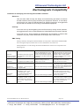
Ultrasound Technologies Ltd
®
fetatrack DD250
desk doppler
Service Manual
Issue 1
©Ultrasound Technologies Ltd, Lodge Way, Portskewett, Caldicot, South Wales NP26 5PS, United Kingdom.
T +44 (0) 1291 425425
F: +44 (0) 1291 427093 E: [email protected] W: www.doppler.co.uk
Ultrasound Technologies Ltd
Contents
ABOUT THIS MANUAL ..................................................................................................................... 1
SAFETY IN USE................................................................................................................................ 2
Special Precautions........................................................................................................................... 2
Electrical Shock Hazard .................................................................................................................... 2
Explosion Hazard .............................................................................................................................. 2
Handling the Delicate Transducers ................................................................................................... 3
Symbols Used ................................................................................................................................... 3
PARTS AND THEIR FUNCTIONS .................................................................................................... 4
Unit Controls ...................................................................................................................................... 4
RS232 Output ................................................................................................................................ 5
Probe Connection .......................................................................................................................... 5
TROUBLESHOOTING ...................................................................................................................... 9
No Display Information on LCD......................................................................................................... 9
Unit Does Not Respond..................................................................................................................... 9
No Sound From Loudspeakers ......................................................................................................... 9
No FHR Information on Display......................................................................................................... 9
No Chart Printed................................................................................................................................ 9
MAINTENANCE .............................................................................................................................. 10
General ............................................................................................................................................ 10
System Cabinet............................................................................................................................ 10
Transducers ................................................................................................................................. 10
ENVIRONMENTAL.......................................................................................................................... 11
Electrommagnetic Compatibility ...................................................................................................... 12
WEEE and RoHS ............................................................................................................................ 13
Dismantling Procedure .................................................................................................................... 14
Circuit Description ........................................................................................................................... 15
Power supply Circuit........................................................................................................................ 15
Battery Low Indicator....................................................................................................................... 16
Ultrasound Transducer .................................................................................................................... 16
Oscillator and Transmitter Amplifier ................................................................................................ 16
Receiver and Detector..................................................................................................................... 17
Audio Amplifier................................................................................................................................. 17
Digital Signal Processing................................................................................................................. 17
Performance .................................................................................................................................... 18
Introduction .................................................................................................................................. 18
Performance Checks ................................................................................................................... 18
Drawings.......................................................................................................................................... 19
Parts Lists .................................................................................................................................... 19
Circuit Data .................................................................................................................................. 19
Assembly Drawings ..................................................................................................................... 19
©Ultrasound Technologies Ltd, Lodge Way, Portskewett, Caldicot, South Wales NP26 5PS, United Kingdom.
T +44 (0) 1291 425425
F: +44 (0) 1291 427093 E: [email protected] W: www.doppler.co.uk
Ultrasound Technologies Ltd
About This Manual
This booklet explains the operation and service of the FETATRACK DD250 Desk doppler.
Care has been taken during the design and manufacture of this product so that it satisfies all
of the current safety standards set down by BS EN60601-1-2006.
To achieve the best from this product read the following sections several times and if you
have any problems in the operation of a particular part of the product then contact your dealer
immediately or contact :
Ultrasound Technologies Ltd
Lodge Way
Portskewett
Caldicot, NP26 5PS
South Wales
UK
Tel
+44 (0) 1291 425425
Fax
+44 (0) 1291 427093
EMAIL [email protected]
This service manual contains circuit descriptions, diagrams, parts and spares lists for the
FETATRACK DD250
To maintain the FETATRACK DD250’s performance it is recommended that it be included in
a periodic maintenance program. The user preventative maintenance program is covered in
this manual. Maintenance outside the scope of the user should be undertaken on an annual
basis by trained service personnel; full details are available from your supplier, service centre
or from Ultrasound Technologies Ltd.
The FETATRACK DD250 is supplied complete with the following: Choice of 2, 3, 5, 8MHz doppler probes
Ultrasound Coupling Gel 0.25ltr
AC line cord
User Instructions
FetatrackDD250 Service Manual Issue1
1
1
1
Page 1
©Ultrasound Technologies Ltd, Lodge Way, Portskewett, Caldicot, South Wales NP26 5PS, United Kingdom.
T +44 (0) 1291 425425
F: +44 (0) 1291 427093 E: [email protected] W: www.doppler.co.uk
Ultrasound Technologies Ltd
Safety
Special Precautions
Your FETATRACK DD250 has been designed for electrical safety.
All the safety and operating instructions should be read before
operating the FETATRACK DD250. Failure to do so could result in
injury to the user, patient, or damage to the system and accessories.
Electrical Shock Hazard
Do not defeat the grounding integrity of this system. Protection
against electrical shock, in the event of failure of basic insulation, is
provided by the connection of the chassis to the safety ground.
Safety grounding occurs only when the 3-wire cable and plug
provided with the system are connected to a properly grounded
receptacle.
Do not remove the system cover. The system should be serviced by
trained and qualified personnel only. Contacting the hazardous
voltages within the system could cause serious injury.
Do not use the system if the power cord has any cuts or openings.
Do not use the transducer if the cable has any cuts or openings.
Do not use the transducer if the transducer face is cracked or
chipped.
Do not immerse the transducer cable connectors in any liquids.
Should the electrical safety fuses have to be replaced, use only fuses
of the same type and rating.
Explosion Hazard
Do not operate or use this system in the presence of flammable
anesthetics, gases or oxygen rich environments as it could lead to
explosion.
FetatrackDD250 Service Manual Issue
Page 2
©Ultrasound Technologies Ltd, Lodge Way, Portskewett, Caldicot, South Wales NP26 5PS, United Kingdom.
T +44 (0) 1291 425425
F: +44 (0) 1291 427093 E: [email protected] W: www.doppler.co.uk
Ultrasound Technologies Ltd
Safety
Handling the Delicate Transducers
The transducers are delicate parts of the ultrasound system and
should be treated with care. The delicate crystals in the transducer
may crack and render the transducer unusable if the transducer is
subject to shock. Room temperature liquids should be used for
cleaning.
NEVER use alcohol or mineral oil as an acoustic coupling agent as
transducer face and cable damage will occur.
ONLY use approved ultrasound coupling gels.
Symbols Used
The following symbols are used on the FETATRACK DD250 and are
in accordance with BS EN60601-1-2006.
Where they are associated with the connection of external
equipment, that equipment must meet the relevant safety standards
in all cases.
Type B equipment
Consult accompanying documents
Alternating Mains Current
DO NOT disposed of with your
normal waste
Unit On / Off
Battery Charge / Discharge state
FetatrackDD250 Service Manual Issue1
Page 3
©Ultrasound Technologies Ltd, Lodge Way, Portskewett, Caldicot, South Wales NP26 5PS, United Kingdom.
T +44 (0) 1291 425425
F: +44 (0) 1291 427093 E: [email protected] W: www.doppler.co.uk
Ultrasound Technologies Ltd
System Operation
FETATRACK DD250 Front Panel Controls
The front panel control area contains 1 button and one rotary volume contol, these
controls are combinded.
(F)
(C)
(A)
(B)
(D)
(E)
(A) IEC 3pin mains cord inlet
(B) Illuminated Mains on/ off switch. The mains switch is illuminated green when AC mains
power is connected and the switch is on, a green mains on indicator (C) is also situated on
the units front panel.
(D) Serial RS232 connection.
(E) Headset connection.
(F) Volume Control / unit on push switch
FetatrackDD250 Service Manual Issue1
Page 4
©Ultrasound Technologies Ltd, Lodge Way, Portskewett, Caldicot, South Wales NP26 5PS, United Kingdom.
T +44 (0) 1291 425425
F: +44 (0) 1291 427093 E: [email protected] W: www.doppler.co.uk
Ultrasound Technologies Ltd
System Operation
RS232 Output
This output is for the connection of an external computer for data transfer. The
maximum voltage that can be applied to this output is 15VDC.
WARNING:
Any external equipment connected to this output must meet the
equivalent MEDICAL safety standard to this product.
Connection must only be made by a qualified technician.
An isolation connection may be necessary when connection is to be
made to a personal computer.
Transducer Input.
Transducers are connected via the pug on the retractile cable.
This is for the connection of Fetatrack DD250 transducers ONLY. The maximum
voltage that can be applied to this output is 15VDC.
FetatrackDD250 Service Manual Issue1
Page 5
©Ultrasound Technologies Ltd, Lodge Way, Portskewett, Caldicot, South Wales NP26 5PS, United Kingdom.
T +44 (0) 1291 425425
F: +44 (0) 1291 427093 E: [email protected] W: www.doppler.co.uk
Ultrasound Technologies Ltd
System Operation
Operating the FETATRACK DD250
In this section, information is supplied which will help you use the FETATRACK DD250 for the fist time.
General
The DD250 is a mains or rechargeable battery operated desk Doppler designed to suit the
needs of the General Practitioner and clinic where multiple disciplines require interchangeable
transducers.
The DD250 can take a choice of 4 transducers, 2 for fetal heart rate detection (2 and 3 MHz)
and 2 for vascular flow detection (5 and 8MHz).
The DD250 provides for the audio presentation of the fetal or vascular signal as well as digital
fetal heart rate detection with the fetal heart rate displayed on an LCD display.
RS232 data port is included for the transfer of data to a PC to review the fetal heart rate traces
(A)
(B)
(C)
FetatrackDD250 Service Manual Issue1
Page 6
©Ultrasound Technologies Ltd, Lodge Way, Portskewett, Caldicot, South Wales NP26 5PS, United Kingdom.
T +44 (0) 1291 425425
F: +44 (0) 1291 427093 E: [email protected] W: www.doppler.co.uk
Ultrasound Technologies Ltd
System Operation
The DD250 includes a storage area from 2 transducers (A). These are held in place using magnetic
retention.
There is a choice of up to 4 transducers that can be used with the DD250, 2 for fetal use and 2 for
vascular use. These are connected to the DD250 using a retractile cable with a latching connector.
The selected transducer (B) is connected to the unit by the connector (C) , to disconnect pull back on
the outer cover of the connector, DO NOT TWIST. To connect a transducer align the red dots and
lightly push the connector into the transducer socket.
The transducers are colour coded at the socket to indicate frequency.
Transducer colour coding
Connector ring colour
2MHz
3MHz
5MHz
8MHz
Red
Orange
Green
Grey
Obstetrics
The DD250 can be used to detect the beating fetal heart from approximately the 10th week of
gestation, though this will vary between patients.
Apply a liberal amount of coupling gel to the area just above the symphysis pubis and position
the transducer face flat against the abdomen. Tilt the transducer slowly until the fetal heart is
heard in
the loudspeaker or headset (in early pregnancy the headset helps to eliminate ambient noise
making it easier to detect the weaker signals).
Later on in pregnancy the best signals are generally found higher up the abdomen.
Avoid sliding the transducer over the abdomen as this results in an increase in the background
noise and makes it more difficult to detect the fetal heart sounds.
The DD250 may be used to locate the position of the placenta, thus aiding in the early
diagnosis of placenta praevia or eliminating placental site where amniocentesis is to be
performed.
The sound from the placenta is an indistinct swishing, caused by bloodflow in many vessels.
There is no distinct beat pattern to the sound. The vessels of the umbilical cord give rise to a
higher pitched sound than the normal fetal heart, with pulsations at the fetal rate.
FetatrackDD250 Service Manual Issue1
Page 7
©Ultrasound Technologies Ltd, Lodge Way, Portskewett, Caldicot, South Wales NP26 5PS, United Kingdom.
T +44 (0) 1291 425425
F: +44 (0) 1291 427093 E: [email protected] W: www.doppler.co.uk
Ultrasound Technologies Ltd
System Operation
Vascular
The DD250 can be used to detect both surface vessels, deeper arteries and veins using
either the 5MHz or 8MHz transducers.
To obtain the best signal, apply a liberal amount of coupling gel to the area of the vein or artery
under investigation. Tilt the transducer at approximately 45 degrees to the vessel. Arteries give
a high pitched pulsatile sound, with veins giving a sound like a roaring wind. The optional
headset helps to eliminate ambient noise, making it easier to detect the weaker signals.
It is also usual for the DD250 to be used in association with a pressure cuff and
sphygmomanometer to indicate the location and extent of arterial occlusion in the form of
ankle/brachial pressure index and segmental pressures.
Due to the variation of leg blood pressure over a wide range with the systemic pressure, the
actual values are less useful than the pressure index, which relates the ankle pressure to the
pressure obtained at the brachial artery. Using the DD250 to measure both pressures will
ensure compatibility. In cases where patients have peripheral arterial disease using the DD250
, due to its high sensitivity, can be the only technique suitable for the measurement of leg
blood pressure.
Pressure Index =
Ankle systolic pressure
Brachial systolic pressure
Normal - ankle systolic pressure > brachial pressure.
Normal pressure index >1
Abnormal pressure index <1
FetatrackDD250 Service Manual Issue1
Page 8
©Ultrasound Technologies Ltd, Lodge Way, Portskewett, Caldicot, South Wales NP26 5PS, United Kingdom.
T +44 (0) 1291 425425
F: +44 (0) 1291 427093 E: [email protected] W: www.doppler.co.uk
Ultrasound Technologies Ltd
Troubleshooting
The information in this section will help you to check and correct common operation and system
problems. Refer to the troubleshooting hints which deal with your problem. Perform the suggested
steps. If the problem is not solved, check once again to make sure that you have used all of the
suggested steps to resolve the problem.
Electronic failures and service procedures are not included in this manual, as all servicing of the
system must be performed by a qualified service technician. Valuable time however can be saved
by documenting the problem .
In general, when you have a problem, check your control settings to be sure that they are in proper
operating position. Consult the appropriate section in this manual for specific information on
particular controls or operating modes.
WARNING:
Disconnect system from the power source before checking fuses
and connections.
Check all connections and fuses. Replace fuses with same type and rating as indicated on the rear
panel of the unit.
No display information on LCD
Verify the system is on and that the fuses are intact.:
·
Keyboard does not respond
·
·
Reset system by turning off then back on.
Verify the system is on and that the fuses are intact.
No sound from loudspeaker.
·
·
·
·
Verify the system is on and that the fuses are intact.
Check volume control is set high.
Check that a transducer has been connected.
If possible change the transducer.
No FHR information on display or FH trace printed on recorder.
·
·
·
Check that a transducer has been connected.
Check connection of the transducer.
Check for audio FH complex and reposition transducer until clearly heard.
Unit will not operate from batteries.
·
·
·
Verify the system is on and that the fuses are intact.
Leave the unit for 5 Hours to charge with mains connected
Check on off button is pressed
FetatrackDD250 Service Manual Issue1
Page 9
©Ultrasound Technologies Ltd, Lodge Way, Portskewett, Caldicot, South Wales NP26 5PS, United Kingdom.
T +44 (0) 1291 425425
F: +44 (0) 1291 427093 E: [email protected] W: www.doppler.co.uk
Ultrasound Technologies Ltd
Maintenance
The following are the user preventative maintenance tasks. It is recommended that these be
performed on a regular basis at a frequency determined by the usage of the equipment, but not less
than once every month.
WARNING:
Before undertaking any of these tasks disconnect the unit from the mains.
General
Check all cables, connectors and transducers for damage and repair or
replace where necessary. The repair may involve your local service centre,
supplier or Ultrasound Technologies Ltd. For advise on any damaged part
contact them immediately.
Cleaning - Enclosure
Clean the exterior of the system with a soft dry cloth. In the event of
stubborn spots, disconnect the system from the power source. Use a soft
cloth that has been dampened - not soaked - in a mild detergent solution.
Be sure to keep excess moisture from entering the cabinet via any
openings that may be present.
Cleaning - Transducers
Use a cloth dampened in a mild detergent solution to clean the transducer
and cable. Remove all traces of the detergent by wiping with a cloth
dampened in clear water. Never soak the transducer cable or connector.
WARNING:
Transducers must never be exposed to gas or heat sterilization or be left
immersed in any liquid for more that a few seconds.
FetatrackDD250 Service Manual Issue1
Page 10
©Ultrasound Technologies Ltd, Lodge Way, Portskewett, Caldicot, South Wales NP26 5PS, United Kingdom.
T +44 (0) 1291 425425
F: +44 (0) 1291 427093 E: [email protected] W: www.doppler.co.uk
Ultrasound Technologies Ltd
Specification
ULTRASOUND
Type:
Transducer:
Operating Frequency
Power Output
Continuous Doppler
2 crystal narrow beam
option of 2, 3, 5, 8 MHz +/- 10%
<5mW/cm² SATA (2, 3 MHz fetal probe)
<15mW/cm² SATA (5 and 8MHz vascular probe)
Response
300Hz—1KHz ( 2, 3 MHz fetal)
300Hz—4KHz ( 5, 8 MHz vascular)
500mW
Software AUTOCORRELATOR
50 to 210 bpm
Audio:
Audio output
Signal Processing
Range:
CONTROLS
Keys:
Controls:
Indicators:
1 key for unit on / off (Push Volume control)
Rotary Volume
LCD Display with icon for battery low and pulse, battery
charge LED, mains on LED.
POWER SUPPLY
Voltage:
Power:
Battery Charge Life:
Battery Charge Time:
100-130 VAC or 200-260 VAC 46/64 Hz
20VA
>30 hours of use (battery's will self discharge when not used)
<5 Hours
ENCLOSURE
Material
Size:
Weight:
Plastic PCABS
32 x 19 x 6 cm
1.9kg
ENVIRONMENTAL
Working temperature
+10°C to +40°C
Relative humidity
30% to 75%
Storage/Transport temperature -10°C to +70°C
COMPUTER INTERFACE
Transfer
Data Rate
Data Standard
Data Format
3 wire RS232
9600 baud
8 bits no parity 1 stop bit
UltraTec Comms Standard
SAFETY
Classification:
Complies with EN60101-1:2006 Class 1 Type B
The following Consumables are available for use with the FETATRACK DD250
Power Cord
Coupling gel (0.25ltr) (12 per box)
This Equipment complies with the essential requirements of the European Council Directive.
93/42/EEC
0120
FetatrackDD250 Service Manual Issue1
Page 11
©Ultrasound Technologies Ltd, Lodge Way, Portskewett, Caldicot, South Wales NP26 5PS, United Kingdom.
T +44 (0) 1291 425425
F: +44 (0) 1291 427093 E: [email protected] W: www.doppler.co.uk
Ultrasound Technologies Ltd
Electromagnetic Compatibility
Guidelines for Identifying and resolving adverse EMC conditions
Emissions
Care has been taken through the design and manufacturing processes to minimise
the EM emissions that may be produced by this equipment. However, in the unlikely
event that the unit causes an EM disturbance to adjacent equipment, we suggest that
the procedure is carried out 'out of range' of the affected equipment.
Immunity
If the user has any doubt regarding the unit's EM immunity during routine operation,
we suggest that the source of EM disturbance is identified and its emissions reduced.
If the user has any doubt regarding the identification and resolution of adverse EM
conditions, they may contact Ultrasound Technologies Ltd to seek advice
EMC Testing
During conformity testing the Fetatrack DD250 was subjected to International Standard EMC
tests. During the majority of these tests no non conformances were observed.
During EN60601-1-1:2001 testing the FetaTrack DD250 was shown to be susceptible to the
following tests.
Effect was a displayed rate of 115 to
125 bpm at each harmonic and sub
Conductive
Test applied a 3Vrms RF magnetic harmonic of the transducer frequency.
disturbance induced field to transducer cables with a 2Hz No disturbance was detected at other
by applied RF field modulation.
frequencies
Radiated RF
Effect was a disturbance to the UA
transducer causing a static UA
Test applied: 3V/m 80Mz to 2.5GHz reading of up to 9 units
Applied test signal is very high for high
sensitivity electronics and non applied
transducers. With correctly applied
transducers interference from in band
RF signals is unlikely.
Normal operation is unaffected and the
static reading can be cancelled by
pressing the toco zero button
Normal mains power is unlikely to cause
such a transient / burst. Displayed rate is
Electrical fast
Test applied: +/-2KV AC power, +/- Effect was a FHR reading of 198 BPM unlikely to occur when transducers are
transients and bursts 1KV Signal Cables
.
connected to a patient.
Electro Static
Discharge
Test applied: +/-2KV, +/-4Kv,
+/8KV Air Discharge, +/-2KV, +/4KV, +/-6KV Contact Discharge.
Repetition Rate 1second
Effect was a FHR reading of 58 BPM
Unit should be used in a low static
environment. Displayed rate is unlikely
to occur when transducers are
. connected to a patient.
Surge
Test applied: +/-0.5KV, +/-1KV, +/2KV AC power line to ground, +/0.5KV, +/-1KV, +/-6KV AC power
line to line
Effect was a FHR reading of 58 BPM
Normal mains power is unlikely to cause
such a surge. Displayed rate is unlikely
to occur when transducers are
. connected to a patient.
FetatrackDD250 Service Manual Issue1
Page 12
©Ultrasound Technologies Ltd, Lodge Way, Portskewett, Caldicot, South Wales NP26 5PS, United Kingdom.
T +44 (0) 1291 425425
F: +44 (0) 1291 427093 E: [email protected] W: www.doppler.co.uk
Ultrasound Technologies Ltd
WEEE and RoHS
Waste Electrical and Electronic Equipment (WEEE) Directive (2002/96/EC)
There is an increasing interest in the proper disposal of used electronic equipment. The European
Union (EU) has developed the WEEE (Waste Electrical and Electronic Equipment) Directive to
ensure that systems for collection, treatment and recycling of electronic waste will be in place
throughout the European Union.
1
Ultrasound Technologies Position with regard to the WEEE Directive
Product recycling is nothing new and Ultrasound Technologies have implemented processes in
each member state where the company has a presence. Ultrasound Technologies will comply with
the provisions of the WEEE Directive and national implementing legislation.
2
Instructions for Disposal of Waste Equipment by Users in Private Households
This symbol on the product or on its packaging indicates that this product must not be disposed
of with your other household waste. Instead, it is your responsibility to dispose of your waste
equipment by handing it over to a designated collection point for the recycling of waste electrical
and electronic equipment. The separate collection and recycling of your waste equipment at the
time of disposal will help to conserve natural resources and ensure that it is recycled in a
manner that protects human health and the environment. For more information about where you
can drop off your waste equipment for recycling, please contact your local waste disposal authority,
your household waste disposal service or the supplier where you purchased the product.
As a producer of electronic devices, Ultrasound Technologies will provide for the financing of the
treatment and recycling of waste returned through these designated collection points in accordance
with local requirements.
3
Instructions for Disposal of Waste Equipment by Commercial Users
For users of Ultrasound Technologies equipment, other than private households, Ultrasound
Technologies will provide free recycling of equivalent medical electronic equipment once a
customer has returned the equipment to Ultrasound Technologies, with all transport and importation
costs paid, and where a replacement product is being supplied by Ultrasound Technologies. Where
a replacement product is not being supplied, recycling services may be provided on request at
additional cost.
RoHS
The RoHS (Restriction of Hazardous Substances) directive (2002/95/EC), compliments the WEEE
Directive by banning the presence of specific hazardous substances in the products at the point of
manufacture.
Ultrasound Technologies is a manufacturer of Medical Devices and is currently exempt from this
directive.
However at Ultrasound Technologies we take our responsibilities to the environment very seriously
and currently 100% of our entire manufacturing process and parts meet the RoHS directive and we
are therefore fully compliant..
FetatrackDD250 Service Manual Issue1
Page 13
©Ultrasound Technologies Ltd, Lodge Way, Portskewett, Caldicot, South Wales NP26 5PS, United Kingdom.
T +44 (0) 1291 425425
F: +44 (0) 1291 427093 E: [email protected] W: www.doppler.co.uk
Ultrasound Technologies Ltd
Disassembly
Dismantling Procedure
12
WARNING:-
ELECTROCUTION RISK
Mains voltages are present at these points and adjustment MUST NOT be untertaken with
the mains lead connected.
NO electrical TEST, SERVICE or INSPECTION of the board should be undertaken without
the board being fitted to the base of the DD250.
Note: Before disassembling the unit, unplug the transducers, accessories
cable (if present), and the power cord from the instrument.
To remove the Top Cover, remove the four screws around the edge on the
bottom of the unit and carefully lift the lid upwards. The Top Cover can now be
removed taking care to disconnect the connections between the lid and the
base..
Internal Layout
The mains and charge board are connected to the base and the audio and
compute board to the lid.
FetatrackDD250 Service Manual Issue1
Page 14
©Ultrasound Technologies Ltd, Lodge Way, Portskewett, Caldicot, South Wales NP26 5PS, United Kingdom.
T +44 (0) 1291 425425
F: +44 (0) 1291 427093 E: [email protected] W: www.doppler.co.uk
Ultrasound Technologies Ltd
Circuit Description
Technical Descriptions
The following sections provides a technical explanation of each of the sections within the
Fetatrack DD250 and its accompanying transducers.: 11
4
Unit Power Supply
The unit operates from either a mains connection or the internal rechargeable battery packs
B1 and B2.
Mains voltage is supplied to the unit via an IEC 3pin mains inlet (J5) where it is routed to
spade jumpers J14, J15, J16, J17, J18 this allows the unit to be set to 110V or 220V input
voltages.
13
WARNING:-
ELECTROCUTION RISK
Mains voltages are present at these points and adjustment MUST NOT be untertaken with
the mains lead connected.
NO electrical TEST, SERVICE or INSPECTION of the board should be undertaken without
the board being fitted to the base of the DD250.
The selected mains voltage is converted into the unit’s operating voltage of 14 – 16VDC by
passing via an encapsulated toroidal transformer T1, L1 to remove any common mode
signals and D3 a diode bridge rectifier. The resultant DC voltage is smoothed by C5 and
C6.
When mains is connected and turned on the mains inlet on/off switch is illuminated green,
this is also mirrored by the DC supply illuminating D7 via R2. The Doppler circuits are
powered from the mains derived DC after it has been regulated to 10V by U3 and passes
through D5 where D6 blocks current being drawn from the batteries.
With the mains connected and switched on, the batteries will be placed into a charge mode.
The state of this mode is indicated by the rate of flashing of D8. The charge controller U2
varies the rate of charge dependent on the state of battery packs B1 and B2 and allows a
current source of 500mA (U1) to be connected or disconnected from the batteries until a
set charge state is reached. R9 and D4 allow a trickle charge to be present at all charge
states. Temperature state of the batteries is monitored by R14 and U2.
When there is no mains connected current is supplied to the Doppler system from the
battery packs B1 and B2 via diode D6. Fuse F1 protects the batteries and circuits from any
short circuits.
The Doppler circuits are connected to the power supply at J2.
FetatrackDD250 Service Manual Issue1
Page 15
©Ultrasound Technologies Ltd, Lodge Way, Portskewett, Caldicot, South Wales NP26 5PS, United Kingdom.
T +44 (0) 1291 425425
F: +44 (0) 1291 427093 E: [email protected] W: www.doppler.co.uk
Ultrasound Technologies Ltd
Circuit Description
(the following descriptions and circuit references refer to the PD1 plus s3 circuits)
The Doppler detection circuits are turned on by the pressing the volume control which
activates an integral push – push switch, which is mounted on the front of the unit. Closing
the switch, grounds the CLK input of U2 pin 11, the output on pin 12 switches on Q2
allowing current to flow into the various circuits.
The unit will remain switched on for approximately 3 minutes from the last detected signal
(monitored by U6) after which it turns off automatically, U6 activates Q1 which pulls the
clock signal at U2 pin 11 low, unless the user forces the unit off by pressing the ON/OFF
switch again.
5
Battery Low Indicator
U6 also monitors the input voltage via R9 and R10. When the voltage on pin 26 drops
below the threshold set by R9 and R10 (7.3V), U6 enables the battery ICON on the LCD
display.
(the following descriptions and circuit references refer to the PD1 doppler transducer circuits)
6
Ultrasound Transducer
The ultrasound transducer operates on the continuous wave Doppler principle. There are a
number of transducer frequencies suitable for different applications, however the basic
operating principles are identical.
Each transducer consists of a pair of piezo ceramic crystals, each crystal pair is arranged
as a transmitter and receiver, the ultrasonic output beam is focused through a lens or
faceplate. With all the transducers, the electronics are housed in the probe.
The oscillator and detector are built up of four discrete sections. These are the master
oscillator, transmitter amplifier, receiver amplifier and detector.
These operate to produce a continuous wave ultrasound signal that is passed to the
transmitting crystal in the transducer.
The signal is then reflected from moving interfaces within the body to the receiver crystal in
the transducer, amplified and then detected so the audio Doppler shift of that moving
interface can be heard audibly and / or converted into a velocity signal.
7
Oscillator and Transmitter Amplifier
Field effect transistor Q2, with L1, C16, C17 and associated components form a Colpitts
oscillator. This oscillator runs at a nominal frequency of 2, 3, 5 or 8MHz producing a
sinewave of amplitude of approximately 5V Pk.
The signal is then fed to output transistor Q3 that drives the transmitter crystal in the
transducer. The signal is fed to the transducer via a tuned transformer L2 (C20), the output
impedance of which is set correctly to match the transducer crystal impedance. The output
drive signal is nominally 1.5V Pk.
FetatrackDD250 Service Manual Issue1
Page 16
©Ultrasound Technologies Ltd, Lodge Way, Portskewett, Caldicot, South Wales NP26 5PS, United Kingdom.
T +44 (0) 1291 425425
F: +44 (0) 1291 427093 E: [email protected] W: www.doppler.co.uk
Ultrasound Technologies Ltd
Circuit Description
8
Receiver and Detector
The reflected Doppler signal is fed via a resonant transformer L4 (C25) to the gate of Q5,
the drain of this FET connects to the source of Q4 to form a cascode amplifier the drain of
which contains the resonant circuit L3,(C21).
From the drain of Q4 the amplitude complex of the received signal is detected by passing
the signal through synchronous detector Q6 with the high frequency signals being filtered
by R12 and C15.
The raw low frequency complex is then amplified and filtered by U1 where its associated
components form a band pass filter amplifier with a bandwidth of 150Hz to 1KHz for the
obstetrics or 300Hz to 4KHz in the vascular transducer.
This signal is passed to the main unit via the retractile cable.
(the following descriptions and circuit references refer to the PD1 plus s3 circuits)
9
Audio Amplifier
The audio signal is routed via the retractile cable to J4 pin 4 on the audio circuit board. The
signal passes through the potentiometer VR1 to the audio amplifier U3, where it is amplified
and output to the loudspeaker connected to J3.
10
Digital Signal Processing
The audio signal is fed from the band pass amplifier, U4d through the AGC circuit formed
around U4c and U7. The microprocessor controls in input gain to maximise the signal
between the limits of 1V and 4.5V at the A/D converter. The signal then passed via the
average value circuit (U4b and U4a) and into the A/D converter U6 pin 25.
The digitally converted signal is correlated to find the input rate which is displayed on the
LCD display driven by the display interface circuit (U5). RS232 data output of the rate
information is provided at connector SK2 as a digital RS232 stream from U8 of +/- 5Vdc.
FetatrackDD250 Service Manual Issue1
Page 17
©Ultrasound Technologies Ltd, Lodge Way, Portskewett, Caldicot, South Wales NP26 5PS, United Kingdom.
T +44 (0) 1291 425425
F: +44 (0) 1291 427093 E: [email protected] W: www.doppler.co.uk
Ultrasound Technologies Ltd
Performance Checks
Introduction
The following sections details tests to ensure that the FETATRACK DD250 is
operating within specification. These tests may be performed in whole or part,
however, if any repairs are carried out to the power supply circuits then it is
recommended that the whole test/calibration procedure is undertaken.
The test procedures may be performed without removal of the circuit board
from the unit.
Performance Checks
The following procedure is intended to provide a means of determining the
functional status of the unit. It should be included as part of a preventive
maintenance plan and should be performed on a regular basis.
1) Plug the monitor line cord into a grounded receptacle of suitable line
voltage and frequency as indicated on the rear panel of the FETATRACK
DD250
2) Turn monitor on. The green front panel LED will illuminate.
3) The display will first show the system selftest followed by the software
revision, this indicates the instrument is switched on and awaiting inputs.
Ultrasound
4) Connect an ultrasound probe to the retractile cable, and increase volume.
5) Place transducer in palm of hand and gently stroke the back of the hand at a
constant rate of about 2 times a second.
6) Check audio volume is present, digital display will display the simulated rate
(approx 120 ).
FetatrackDD250 Service Manual Issue1
Page 18
©Ultrasound Technologies Ltd, Lodge Way, Portskewett, Caldicot, South Wales NP26 5PS, United Kingdom.
T +44 (0) 1291 425425
F: +44 (0) 1291 427093 E: [email protected] W: www.doppler.co.uk
Ultrasound Technologies Ltd
Drawings
The following pages contain drawing data to assist in the service of the product.
Parts lists (Bills of material)
Fetatrack DD250 Mains Battery Circuit
Fetatrack DD250 PD1 Plus Circuit
Fetatrack DD250 Pocket Doppler Transducer 2MHz
Fetatrack DD250 Pocket Doppler Transducer 5MHz
Fetatrack DD250 Pocket Doppler Transducer 8MHz
Circuit Data
Fetatrack DD250 Mains Battery Circuit
Fetatrack DD250 PD1 Plus s3 Audio Circuit
Fetatrack DD250 PD1 Plus s3 Digital Signal Processor
Fetatrack DD250 Pocket Doppler Fetal Transducer 2MHz
Assembly Drawings
Fetatrack DD250 Assembly Base
Fetatrack DD250 Assembly Top
Fetatrack DD250 Assembly Main PCB
Fetatrack DD250 Assembly PD1 Plus PCB
Fetatrack DD250 Assembly Main
FetatrackDD250 Service Manual Issue1
Page 19
©Ultrasound Technologies Ltd, Lodge Way, Portskewett, Caldicot, South Wales NP26 5PS, United Kingdom.
T +44 (0) 1291 425425
F: +44 (0) 1291 427093 E: [email protected] W: www.doppler.co.uk
3
4
2
1
3
7
1
C10 +
100nF
C8
100uF
C12
100uF
C16
680pF
3
C20
220pF
B
R2
2K2
C7 +
100nF
6
3
1
D
3
G
0841
L1
TxSig
A
L2
0876
3
3
6
C
1
B
2
E
(VR1)
S
10nF
C18
2
4
C23
1nF 2
1
1
D1
BZX84C6V2
2
C17
330pF
C5
100uF
8
R14
27K
100R
R13
C3 +
100nF
MMBF4416
Q2
A
Vrf
E
C
Q1
BC848B
5
BC848B
Q3
2
R7
22R
1
R15
1K5
C14
10nF
R17
10R
C24
100nF
R11
2K2
R20
180K
1
B
J1
2
B
Vrf
3
4
1
C19
220pF
6
R5
100K
2
2
3
MMBF4416
Q6
C15
1nF
R18
100K
R12
100K
D
1
3
G
S
2
C26
100nF
R19
100K
R6
100K
D
1K0
R3
1K0
R8
C4
1uF
1
3
G
S
C9
1nF
R1
2K2
C2
100nF
C
Q5
MMBF4416
4
I-
I-
L3
0842
Q4
MMBF4416
TL072
100K
R10
TL072
S
1
5
10nF
C13
7
I+
3
4
U1
10nF
C6
C1
100nF
I+
1
8
8
U1
C21
470pF
3G
R9
100K
D
R4
100K
Transducer Connector
C22
100nF
2
1
C25
220pF
4
3
6
R16
10R
RxSig
C11
1uF
Issue
1
2
3
4
5
D
3
4
5
Date
March 98
15/05/98
18/01/99
18/05/00
12/05
158
181
Drawn: nas - utl Drg No: PD1D110-ASSY
Lodge Way
Portskewett, Caldicot
Date: 18/05/2000
South Wales. NP26 5PS. UK Name: FETALTDR_R5 Sheet 1
of 1
Copyright
ultratec 2003
2
ECN
Pocket Doppler Fetal Transducer 2MHz
Ultrasound Technologies Ltd
1
C
L4
0838
6
7
8
D
D
E
F
T1
Mains Transformer
11
DC Voltage at 230VAC = 15.5V
DC Voltage at 200VAC = 13.4V
DC voltage 15.5V
DC current 900mA
C2
100nF
C5
2,200uF
DC+
AC1
3
3
DC-
2
AC2
2
2
4
4
100R
R9
Fast charge is 500mA
2
4
14
10BQ040
1
2
D1
2
Charge
4
4
10BQ040
1
J1
3
1
2
VsenOP
TrefH
F/TOP
Tsen
Gnd
TrefL
R12
10K
8
7
I = 72.7uA
with Vbat = 9.6
6
5
R8
27K
MC33340
R13
22K
Mains On
LED Indicators
R50 3 S
100K
G1
5
U3
LM317S
Vout
TAB
C3
10uF
2
2
4
+
C7
100nF
Adj
1
+
C1
100nF
BATTPACK4V8
4.8V
+
1
J6
B2
3
10K NTH4G
4
RS232_Rx
5
RS232_Tx
J11
1
1
2
2
5
1
1
2
10BQ040
C8
10uF
J7
J2
DD250 DC Output
1
AC power on
12VDC, 200mA
J8
1
3
3
4
4
2
10K LOG
R6
1K5
1
2
1
2
1
J9
1
J10
6
LED PCB
R7
220R
1
J12
SK2
Socket PCB
Battery State
7
2
4
3
1
4
RS232
6
LED out
SK1
Parts in close proximity
R5
200R
Min dropout voltage = 2V (input / output)
Min output voltage for min input = 11.4V
Audio Socket
2
4
3
1
2
BATTPACK4V8
4.8V
D5
12.13V
Vin
D
B1
22K
R51
2
3
+
R14
C9
100nF
R10
4K7
J4
1
1
F1
Vcc
3
4
3
3
R11
100K
v sense = 1.6V
VsenIP
C4
100nF
2
2
Vertical Mounting Blades 0.25"
RS 534-834
J3
1
SPD8P06SM
Q3
100R
R3
1
N
L
1
Isen = 10nA
R2
6K8
4
Nuvotem 70052K RS223-9339
Transformer Output 12VAC 15VA
10BQ040
U2
R1
6K8
AC4
1
0.75A
TAB
AC1
3
D2
2
Adj
AC3
SW1
POLYFUSE0A75
Vout
4
AC2
At 80% full charge I = 43mA
2R2
R4
Vin
3
13
1
D4
3
5
L1
1000uH
2
U1
LM317S
12
1
D3
1
PE
C6
2,200uF
2
J5
6
Common mode rejection
DBLS203G
1
H
D7
1
G
IEC Mains input / fuse and On/Off Switch
D8
C
LGN971
B
LYN971
A
J13
Issue
ECN
Date
1
2
3
3
4
7
Mar 09
May 10
Jan 11
5
S1
LED in
Volume and on/off switch
Volume PCB
Copyright
ultratec 2011
A
Mains / Battery circuit for DD250
Drawn: Nas
Drg No:
D250C100-103
Lodge Way
Date:
Portskewett, Caldicot
of 1
South Wales. NP26 5PS. UK Name: DD250POWER_3 Sheet 1
Ultrasound Technologies Ltd
8
B
C
D
E
F
G
H
8
4
Q2
FDN352AP
C11
100uF
R11
2K2
R9
12K
Battery Input
U2
8
SET
11
CLK
9
D
10
RESET
1
J2
E
C22
100uF
VSewardprobe
A
C19
100uF
2
3
BatteryCondition {02}
+
13
Q
12
Q
D2
BZX84C6V2
R10
4K7
R5
1M
CD4013
C3
100nF
C12
100uF
1
R1
1M
Unit On / Off control
C21 +
100nF
3
C18 +
100nF
2
3
+
C7
100nF
8
Q3
BC848B
1
R4
1M
10BQ040
G1
2
A
7
B
1
2
2
6
C
1
S
D1
J1
5
3
3
VddSw {02}
2
D
1
+
C6
1u0F
probe_switch
3
B
UnitShutDown {02}
VddSw {02}
1
Q
2
Q
CD4013
5
6
C8
220uF
+ +
100nF
C20
C9
220uF
+
C15
10uF
C14
10nF
VSewardprobe
U1
C1
100nF
+
VO-
V1+
CAP+
100uF
C2
GND
CAP-
SK1
2
4
3
1
8
2
3
C4
10uF
+
C5
100nF
C
8
R8
22K
U3
5
P
LM386M
M
R7
10R
VR1
100K
3
2
100nF
C17
Volume Control
7
4
5
C10
100uF
R3
100R
+
TP1
J3
4
1
2
SI7661
J4
3
4
1
C
2
probe_switch
6
U2
6
SET
3
CLK
5
D
4
RESET
Transducer
Power
Connector
1
AudioComplex {02}
47R
R6
G
1
VddSw {02}
S
2
VddSw {02}
BSS138
Q1
B
10K
R2
D
C16
10uF
C13
100nF
+
Loudspeaker
Issue
1
2
3
4
5
6
7
8
D
ECN
Date
June 98
Sept 99
Nov 99
Jun 00
Aug 02
Jan 05
Aug 05
Aug 07
176
178
182
210
228
230
PD1 Plus s3 Audio Circuit
Drawn: NAS
Drg No:
Lodge Way
100-0002-00
Date:
Portskewett, Caldicot
Sheet 1
of 2
South Wales. NP26 5PS. UK Name: PD1PLUS3
Ultrasound Technologies Ltd
Copyright
ultratec 2007
1
2
3
4
5
6
7
8
D
1
2
3
4
5
6
7
8
LCD Interface
Disp1[1:7]
1
bp
A
S3
3
DispSym1
1
26
R
2
25 bp
3
24
Disp1[3]
Disp1[6]
4
23
Disp1[4]
Disp1[7]
5
22
Disp1[5]
Disp2[2]
6
21
Disp2[3]
Disp2[1]
7
20
Disp2[4]
EZPQ
Disp2[6]
8
19
Disp2[5]
EZPCK
9
18
Disp2[7]
Disp3[1] 10
17
Disp3[3]
Disp3[6] 11
16
Disp3[4]
12
15
Disp3[5]
13
14
Disp3[7]
DispSym2
6
STR
Disp1[2]
Disp1[1]
Disp3[2]
S4
4
5
7
8
C25
100nF
9
10
11
12
13
FR
14
15
16
17
18
J5
19
20
21
Disp3[1:7]
B
22
23
24
25
26
1
S2
S1
2
S5
R
S6
STR
S7
D0
S8
Vlcd
S9
VDD
S10
VSS1
S11
DI
S12
CLK
S13
FR
S14
S40
S15
S39
S16
S38
S17
S37
S18
S36
S19
S35
S20
S34
S21
S33
S22
S32
S23
S31
S24
S30
S25
S29
S26
S28
C37
100nF
U8
U5
Disp2[1:7]
S27
C33
100nF
52 Disp1[1]
51 Disp1[2]
3
50 Disp1[3]
4
49 Disp1[4]
C34
100nF
48 Disp1[5]
R19
10K
47 Disp1[6]
R21
10K
R22
10K
Disp2[1]
FR
44
Disp2[2]
R
43
Disp2[3]
42
Disp2[4]
41
Disp2[5]
40
Disp2[6]
39
Disp2[7]
22
23
18
STR
19
Agc1
Agc2
Agc3
Disp3[1]
37
Disp3[2]
36
Disp3[3]
35
Disp3[4]
34
Disp3[5]
33
Disp3[6]
32
Disp3[7]
Agc4
40
41
42
43
56
57
UnitShutDown {01}
EZPD
EZPQ
DispSym1
30
C1-
V-
2
6
C38
100nF
C2+
C2-
TP5
EZPCK
DispSym2
58
12
13
14
15
29
PTC0
UCTS0
PTC1
URTS0
PTC2
URXD0
PTC3
UTXD0
UCTS1
PTA0
URTS1
PTA1
URXD1
PTA2
UTXD1
PNQ1
JTAG_EN
PNQ4
TCLK
PNQ7
TDI
TDO
SPI_DIN
TMS
SPI_DOUT
26
BatteryCondition {01}
27
V6108
28
36
35
34
33
TRST
30
6
12
Rx_Data
9
61
2
T1out
T2in
T2out
R1out
R1in
R2out
R2in
Tx_Data
RS232
14
7
13
8
MAX3232E
63
TP12
62
17
44
50
51
49
1
EZPD
54
RCON
16
SCL
AN2
SDA
AN3
ALLPST
AN4
AN5
TEST
AN6
RSTI
AN7
VRH
EXTAL
VRL
XTAL
Vstby
B
3
EZPCS
4
24
5
R32
1K0
AN0
AN1
J6
2
EZPQ
EZPCK
SPI_CS
RSTO
31
10
TP10
5
SPI_CLK
CLKMOD0
25
fetal_signal_complex
7
T1in
PTA3
28
27
11
4
A
SK2
2
4
3
1
RS232_Tx
U6
45
31
V+
RS232_Rx
5
46 Disp1[7]
38
C1+
6
8
7
Unit Programming Interface
Vcc is 3.3V
9
55
3
R33
10K
TP13
59
reset
60
47
device power on reset
EXTAL
46
C31
22pF
37
R31
1M
C40
1uF
X1
11.05920MHz
C23
1nF
R13
68K
LowPass Filter (5Hz)
I+
8
6
LM324M
Precision Rectifier
R25
100K
VddSw {01}
VddSw {01}
I-
5
I-
9
4
U4
LM324M
I+
14
10
I-
I+
11
13
3
C42
100nF
ZSR330G
C30
10nF
12
11
R24
10K
R26
10K
R27
10K
R29
10K
U7
2
C28
47nF
R23
10K
YA
CONTA
XA
3
D
YB
CONTB
XB
9
YC
CONTC
YD
CONTD
XC
10
XD
Note: Power Rail +3.3 - 0V
1
IN
C41
100nF
AudioComplex {01}
LM324M
11
R20
330K
D3
BZX84C2V7
4
C39
10uF
1
3
fetal_signal_complex
7
4
U4
C35
100nF
OUT
R30
100K
Fetal Complex
BAS16
D4
U4
C
U9
1
C36 +
100nF
330K
R28
11
1uF
C26
C32
22pF
C29
1nF
3
TP2
C27
100nF
I+
Low Pass filter fo = 220Hz
R18
10K
LM324M
3
100K
R12
I-
R16
22K
1
2
R15
68K
U4
10K
R17
VddSw {01}
TP3
4
TP4
1
100nF
C24
VddSw {01}
R14
47K
MCF5212CAE66
C
VddSw {01}
XTAL
2
3
4
5
74HC4066
13
Agc1
1
5
Agc2
4
6
Agc3
8
12
Agc4
11
Issue
ECN
1
2
3
4
5
6
7
8
176
178
182
210
228
230
PD1 Plus s3 Digital Signal Processor
Drg No: 100-0002-00
Drawn: NAS
Lodge Way
Portskewett, Caldicot
Date:
South Wales. NP26 5PS. UK Name: PD1PLUS3
Sheet 2
of 2
Ultrasound Technologies Ltd
FHR Agc
6
Copyright
ultratec 2007
Date
June 98
Sept 99
Nov 99
June 00
Aug 02
Jan 05
Aug 05
Aug 07
7
8
D