1
®
TECHNICAL MANU
AL
MANUAL
GKS9
40" 90% Gas Furnaces
• Refer to Service Manual RS6610004* for installation, operation, and troubleshooting information.
• All safety information must be followed as provided in the Service Manual.
• Refer to the appropriate Parts Catalog for part number information.
• Model numbers listed on page 3.
®
C
This manual is to be used by qualified, professionally trained HVAC technicians only. Goodman
does not assume any responsibility for property damage or personal injury due to improper
service procedures or services performed by an unqualified person.
Copyright © 2006-2007, 2009-2010 Goodman Manufacturing Company, L.P.
US
RT6612017 Rev. 3
February 2010
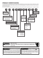
PRODUCT IDENTIFICATION
The model and manufacturing number are used for positive identification of component parts used in manufacturing. When
engineering and manufacturing changes take place where interchangeability of components are affected, the manufacturing number will change.
It is very important to use the model and manufacturing numbers at all times when requesting service or parts information.
G
K
S
9
045 3 B
X
A
A
Product Type
Minor Revision
G: Gas Furnace
A: Initial Release
Major Revision
Airflow
Capability
Supply Type
C: Counterflow/Horizontal
M: Upflow/Horizontal
K: Residential Upflow
3: 1200
A: Initial Release
Additional Features
4: 1600
N: Natural Gas
5: 2000
X: Low NOx
Furnace Type
S: Single Stage/Multi-Speed
Cabinet Width
A: 14"
Model Family
B: 17 1/2"
9: Air Command 90
C: 21"
(40" Height)
D: 24 1/2"
Nominal Input
045:
070:
090:
115:
WARNING
HIGH VOLTAGE!
Disconnect ALL power before servicing or installing this unit. Multiple power
sources may be present. Failure to do so may cause property damage, personal
injury or death.
Goodman will not be responsible
for any injury or property damage
arising from improper service or service procedures. If
you install or perform service on this unit, you assume
responsibility for any personal injury or property damage
which may result. Many jurisdictions require a license to
install or service heating and air conditioning equipment.
WARNING
2
45,000 Btuh
70,000 Btuh
90,000 Btuh
115,000 Btuh
Installation and repair of this unit
should be performed ONLY by
individuals meeting the requirements of an "entry level technician", at a minimum, as
specified by the Air-Conditioning, Heating, and Refrigeration Institute (AHRI). Attempting to install or repair this
unit without such background may result in product
damage, personal injury or death.
WARNING
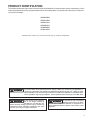
PRODUCT IDENTIFICATION
The model and manufacturing number are used for positive identification of component parts used in manufacturing. When
engineering and manufacturing changes take place where interchangeability of components are affected, the manufacturing number will change.
GKS90453BX*
GKS90703BX*
GKS90704CX*
GKS90904CX*
GKS90905DX*
GKS91155DX*
* Indicates minor revision & is not used for order entry or inventory management
WARNING
The United States Environmental Protection Agency (“EPA”) has issued various regulations regarding the introduction and disposal of refrigerants introduced into this unit. Failure to follow
these regulations may harm the environment and can lead to the imposition of substantial fines.
These regulations may vary by jurisdiction. Should questions arise, contact your local EPA office.
Do not connect or use any device
that is not design certified by
Goodman for use with this unit.
Serious property damage, personal injury, reduced unit
performance and/or hazardous conditions may result
from the use of such non-approved devices.
WARNING
To prevent the risk of property
damage, personal injury, or death,
do not store combustible materials or use gasoline or
other flammable liquids or vapors in the vicinity of this
appliance.
WARNING
3
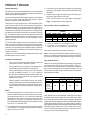
PRODUCT DESIGN
General Operation
The GKS9 furnaces are equipped with an electronic ignition
device used to light the burners and an induced draft blower
to exhaust combustion products.
An interlock switch prevents furnace operation if the blower
door is not in place. Keep the blower access door in place
except for inspection and maintenance.
This furnace is also equipped with a self-diagnosing electronic control module. In the event a furnace component is
not operating properly, the control module LED will flash on
and off in a factory-programmed sequence, depending on
the problem encountered. This light can be viewed through
the observation window in the blower access door. Refer to
the Troubleshooting Chart for further explanation of the LED
codes and Abnormal Operation - Integrated Ignition Control
section in the Service Instructions for an explanation of the
possible problem.
The rated heating capacity of the furnace should be greater
than or equal to the total heat loss of the area to be heated.
The total heat loss should be calculated by an approved
method or in accordance with “ASHRAE Guide” or “Manual
J-Load Calculations” published by the Air Conditioning Contractors of America.
*Obtain from: American National Standards Institute 1430
Broadway New York, NY 10018
Location Considerations
•
The furnace should be as centralized as is practical
with respect to the air distribution system.
•
Do not install the furnace directly on carpeting, tile, or
combustible material other than wood flooring.
•
When suspending the furnace from rafters or joists,
use 3/8" threaded rod and 2” x 2” x 3/8” angle as
shown in the Installation and Service Instructions. The
length of the rod will depend on the application and
clearance necessary.
•
When installed in a residential garage, the furnace
must be positioned so the burners and ignition source
are located not less than 18 inches (457 mm) above
the floor and protected from physical damage by vehicles.
Notes:
1. Installer must supply one or two PVC pipes: one for combustion air (optional) and one for the flue outlet (required).
Vent pipe must be either 2” or 3” in diameter, depending
upon furnace input, number of elbows, length of run and
installation (1 or 2 pipes). The optional Combustion Air
Pipe is dependent on installation/code requirements and
must be 2” or 3” diameter PVC.
2. Line voltage wiring can enter through the right or left side
of the furnace. Low voltage wiring can enter through the
right or left side of furnace.
4
3. Conversion kits for high altitude natural or propane gas
operation are available. See High Altitude Derate chart
for details.
4. Installer must supply the following gas line fittings, depending on which entrance is used:
Left -- Two 90º Elbows, one close nipple, straight pipe.
Right -- Straight pipe to reach gas valve.
Accessibility Clearances (Minimum)
MINIMUM CLEARANCES TO COMBUSTIBLE MATERIALS
(INCHES)
POSITION* FRONT SIDES
Upflow
0
Counterflow
1
0
Horizontal
*=
1
REAR
0
0
TOP
1
1
FLUE
0
0
FLOOR
C
NC
0
4
0
C
6
All positioning is determined as installed unit is view ed from the front.
C= If placed on combustible floor, floor MUST be w ood only.
NC= For instalaltion on non-combustible floors only. A combustible
subbase must be used for installations on combustible flooring.
36" at front is required for servicing or cleaning.
Note: In all cases accessibility clearance shall take precedence over clearances from the enclosure where accessibility clearances are greater. All dimensions are given in inches.
High Altitude Derate
When this furnace is installed at high altitude, the appropriate High Altitude orifice kit must be installed. This is required due to the natural reduction in the density of both the
gas fuel and combustion air as altitude increases. The kit
will provide the proper design certified input rate within the
specified altitude range.
PROPANE AND HIGH ALTITUDE KITS
0 - 7,000 ft.
7,001-9,000 ft.
9,001-11,000
ft.
7,001-11,000
ft.
7,001-11,000
ft.
TBD
TBD
TBD
TBD
LPT-00*1
LPT-03*2
Propane
Conversion Kit
(#55 Orifices)
1
2
Supports White-Rodgers 1-stage valve only
Supports both Honeyw ell and White-Rodgers 1-stage valves
High altitude kits are purchased according to the installation altitude and usage of either natural or propane gas. Refer
to the chart above for a tabular listing of appropriate altitude
ranges and corresponding manufacturer’s high altitude Natural Gas and Propane Gas kits. For a tabular listing of appropriate altitude ranges and corresponding manufacturer's High
Altitude Pressure Switch kits, refer to either the Pressure
Switch Trip Points & Usage Chart in this manual or the Accessory Charts in Service Instructions.
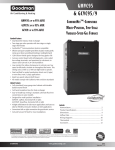
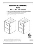
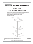
COMPONENT IDENTIFICATION
BURNER COMPARTMENT
3
6
6
5
4
7
8
9
10
25
11
12
13
2
14
1
15
27
17
29
18
26
BLOWER COMPARTMENT
16
17
28
18
19
24
20
21
23
22
Upflow/Horizontal
1
Gas Valve
16 Electrical Connection Inlets (Alternate)
2
Gas Line Entrance (Alternate)
17 Coil Front Cover Drain Port
3
Combustion Air Intake Connection / “Coupling”
18 Drain Line Penetrations
4
Hot Surface Igniter
19 Blower Door Interlock Switch
5
Burners
20 24-Volt Thermostat Connections
6
Rollout Limit
21 Integrated Control Module
7
Flame Sensor
(with fuse and diagnostic LED)
8 Flue Pipe Connection / “Coupling”
22 Transformer (40 VA)
9 Flue Pipe (Internal)
23 Circulator Blower
10 Primary Limit
24 Auxiliary Limit
11 Pressure Switch
25 Gas Manifold
12 Gas Line Entrance
26 Junction Box
13 Rubber Elbow
27 Coil Front Cover
14 Flue Pipe Connection (Alternate)
28 Drain Trap
15 Induced Draft Blower
29 Electrical Connection Inlets
5
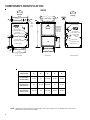
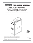
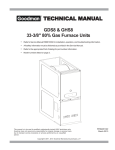
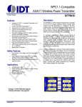
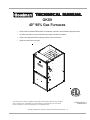
COMPONENT IDENTIFICATION
GKS9
AIR
DISCHARGE
AIR
DISCHARGE
A
B
(DISCHARGE)
20 13/16
C
AIR
INTAKE
PIPE
2" PVC
STANDARD GAS
SUPPLY HOLE
CONDENSATE
DRAIN TRAP
w/ 3/4" PVC
DISCHARGE
(RIGHT OR
LEFT SIDE)
HIGH VOLTAGE
ELECTRICAL HOLE
HIGH VOLTAGE
ELECTRICAL HOLE
LEFT SIDE
DRAIN LINE HOLES
1 1/2
DRAIN
TRAP
LOW VOLTAGE
ELECTRICAL HOLE
2
LOW VOLTAGE
ELECTRICAL HOLE
SIDE CUT-OUT
1 5/8
1
RIGHT SIDE
DRAIN LINE
HOLES
SIDE CUT-OUT
22 1/16
UNFOLDED FLANGES
UNFOLDED FLANGES
23 9/16
FOLDED FLANGES
FOLDED FLANGES
LEFT SIDE VIEW
FRONT VIEW
RIGHT SIDE VIEW
Cabinet Size
A
B
C
D
E
GKS90453BX*
GKS90703BX*
17-1/2
16
12-15/16
12-1/8
13-5/8
GKS90704CX*
GKS90904CX*
21
19-1/2
15-15/16
16
17-1/2
GKS90905DX*
GKS91155DX*
24-1/2
23
20-7/16
19-3/8
20-7/8
All dimensions are in inches.
NOTE: Airflow area will be reduced by approximately 18% if duct flanges are not unfolded. This could cause
performance issues and noise issues.
6
PRODUCT DESIGN
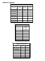
PRESSURE SWITCH TRIP POINTS AND USAGE CHART
MODEL
NEGATIVE PRESSURE
ID BLOWER
WITH FLUE NOT FIRING
TYPICAL SEA
LEVEL DATA
NEGATIVE PRESSURE
ID BLOWER
WITH FLUE FIRING
TYPICAL SEA
LEVEL DATA
NEGATIVE PRESSURE
COIL COVER
WITH FLUE NOT FIRING
TYPICAL SEA
LEVEL DATA
NEGATIVE PRESSURE
COIL COVER
WITH FLUE FIRING
TYPICAL SEA
LEVEL DATA
GKS90453BX*
-1.40
-1.20
-0.52
-0.37
GKS90703BX*
-1.30
-1.10
-0.52
-0.37
GKS90704CX*
-1.30
-1.10
-0.52
-0.37
GKS90904CX*
-1.10
-0.95
-0.52
-0.37
GKS90905DX*
-0.90
-0.75
-0.52
-0.37
GKS91155DX*
-1.30
-1.10
-0.52
-0.37
(1) Data given for the flue not firing is least negative pressure required for switch to close.
(2) Data given for the flue firing is least negative pressure required for the switch to remain closed.
PRESSURE SWITCH TRIP POINTS AND USAGE
0 to 7,000 ft.
7,001 to 11,000 ft.
MODEL
TRIP POINT
COIL COVER
PRESSURE
SWITCH
COIL COVER
PRESSURE
SWITCH
PART #*
TRIP POINT
ID BLOWER
PRESSURE
SWITCH
ID BLOWER
PRESSURE
SWITCH
PART #*
TRIP POINT
COIL COVER
PRESSURE
SWITCH
TRIP POINT
ID BLOWER
PRESSURE
SWITCH
HIGH
ALTITUDE
KIT
GKS90453BX*
-0.37
20197312
-1.20
0130F00001P
TBD
TBD
TBD
GKS90703BX*
-0.37
20197312
-1.10
0130F00000P
TBD
TBD
TBD
GKS90704CX*
-0.37
20197312
-1.10
0130F00000P
TBD
TBD
TBD
GKS90904CX*
-0.37
20197312
-0.95
0130F00002P
TBD
TBD
TBD
GKS90905DX*
-0.37
20197312
-0.75
0130F00004
TBD
TBD
TBD
GKS91155DX*
-0.37
20197312
-1.10
0130F00001P
TBD
TBD
TBD
Note: For installations in Canada, this 90% furnace is certified only to 4500.ft.
Note: All negative pressure readings are in inches of water column (" w.c.).
* GKS9 furnaces are shipped without coil cover pressure switches. All GKS9 models are shipped from the factory as Dedicated Upflow but can
be installed as a Horizontal Left or a Horizontal Right, ONLY after installing GKS9 Horizontal Installation Kit 0270K00012, which contains
Pressure Switch 20197312.
7
PRODUCT DESIGN
T.O.D. PRIMARY LIMIT
Part Number
20162903
20162904
20162906
Open Setting (°F)
160
150
170
1
GKS90453BX*
GKS90703BX*
1
GKS90704CX*
1
1
GKS90904CX*
1
GKS90905DX*
1
GKS91155DX*
ROLLOUT LIMIT SWITCHES
Part Number
10123514
or
10123533
Open Setting (°F)
200
GKS90453BX*
1
GKS90703BX*
2
GKS90704CX*
2
GKS90904CX*
2
GKS90905DX*
2
GKS91155DX*
2
AUXILIARY LIMIT SWITCHES
Part Number
10123519
10123535
Open Setting (°F)
160
150
GKS90453BX*
1
GKS90703BX*
1
GKS90704CX*
1
GKS90904CX*
1
GKS90905DX*
1
GKS91155DX*
8
1
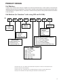
PRODUCT DESIGN
Coil Matches:
A large array of Amana® brand coils are available for use with the GKS9 furnaces, in either upflow or horizontal (with
appropriate pressure switch kit) applications. These coils are available in both cased and uncased models (with the option
of a field installed TXV expansion device). These 90%+ furnaces match up with the existing Amana® brand coils as shown
in the chart below.
Coil Matches (for Goodman® units using R22 and R-410A):
C
A
P
F
1824
A
6
EXPANSION
DEVICE:
F: Flowrater
PRODUCT
TYPE:
C: Indoor Coil
CABINET FINISH:
U: Unpainted
P: Painted
N: Unpainted Case
APPLICATION
A: Upflow/Downflow Coil
H: Horizontal A Coil
S: Horizontal Slab Coil
A
REVISION
A: Revision
REFRIGERANT
CHARGE:
6: R-410A or R-22
2: R-22
4: R-410a
NOMINAL WIDTH FOR GAS FURNACE
A: Fits 14" Furnace Cabinet
B: Fits 17 1/2" Furnace Cabinet
C: Fits 21" Furnace Cabinet
D: Fits 24 1/2" Furnace Cabinet
N: Does Not Apply (Horizontal Slab Coils)
NOMINAL CAPACITY RANGE
@ 13 SEER
1824: 1 1/2 to 2 Tons
3030: 2 1/2 Tons
3636: 3 Tons
3642: 3 to 3 1/2 Tons
3743: 3 to 3 1/2 Tons
4860: 4 & 5 Tons
4961: 4 & 5 Tons
• All CAPF coils in B, C, & D widths have insulated blank off plates for use with one size smaller furnaces.
• All CAPF coils have a CAUF equivalent.
• All CHPF coils in B, C & D heights have an insulated Z bracket for use with one size smaller furnace.
• All proper coil combinations are subject to being ARI rated with a matched outdoor unit.
9
PRODUCT DESIGN
Thermostats:
NOTE: Complete lineup of thermostats can be found in the Thermostat Specification Sheets.
Filters:
Filters are required with this furnace and must be provided by the installer. The filters used must comply with UL900 or
CAN/ULCS111 standards. Installing this furnace without filters will void the unit warranty.
Upflow Filters
This furnace has provisions for the installation of return air filters at the side and/or bottom return. The furnace will
accommodate the following filter sizes depending on cabinet size:
Cabinet
Width
(in.)
All
SIDE RETURN
Approx.
Nominal
Flow
Area
Filter Size
(in.)
(in2)
16 x 25 x 1
400
BOTTOM RETURN
Approx.
Cabinet
Nominal
Flow
Area
Width
Filter Size
(in.)
(in.)
(in2)
17-1/2
14 x 25 x 1
350
21
16 x 25 x 1
400
24-1/2
20 x 25 x 1
500
Refer to Minimum Filter Area tables to determine filter area requirement. NOTE: Filters can also be installed elsewhere in
the duct system such as a central return.
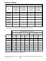
COOLING AIRFLOW REQUIREMENT (CFM)
600
800
1000
1200
1400
1600
2000
0453_X*
376*
384
480
576
---
---
---
0703_X*
---
564*
564*
564*
672
---
---
0704_X*
---
---
564*
564*
672
768
---
0904_X*
---
---
752*
752*
752*
768
---
0905_X*
---
---
---
752*
752*
768
800
1155_X*
---
---
---
940*
940*
940*
800
Input__Airflow
Input__Airflow
COOLING AIRFLOW REQUIREMENT (CFM)
600
800
1000
1200
1400
1600
2000
0453_X*
188*
192
240
288
---
---
---
0703_X*
---
282*
282*
282*
336
---
---
0704_X*
---
---
260*
260*
336
384
---
0904_X*
---
---
376*
376*
376*
384
---
0905_X*
---
---
---
376*
376*
384
480
115_X*
---
---
---
470*
470*
470*
480
*Minimum filter area dictated by heating airflow requirement.
*Minimum filter area dictated by heating airflow requirement.
Disposable Minimum Filter Area (in2)
Permanent Minimum Filter Area (in2)
[Based on a 300 ft/min filter face velocity]
[Based on 600 ft/min filter face velocity]
10
FURNACE SPECIFICATIONS
GKS9
0453BX*
GKS9
0703BX*
GKS9
0704CX*
GKS9
0904CX*
GKS9
0905DX*
GKS9
1155DX*
Input (US)
46,000
69,000
69,000
92,000
92,000
115,000
Output (US)
42,800
64,400
63,900
86,000
86,000
106,500
Input (CAN)
46,000
69,000
69,000
92,000
92,000
115,000
Output (CAN)
42,800
64,400
63,900
86,000
85,300
106,500
92.1%
92.1%
92.1%
92.1%
92.1%
92.1%
Rated External Static (" w.c.)
.20 - .50
.20 - .50
.20 - .50
.20 - .50
.20 - .50
.20 - .50
Temperature Rise (°F)
35 - 65
35 - 65
35 - 65
35 - 65
35 - 65
35 - 65
ID Blower Pressure Switch Trip Point (" w.c.)
-1.20
-1.10
-1.10
-0.95
-0.75
-1.10
Blower Wheel (D" x W")
10 x 8
10 x 8
10 x 10
10 x 10
11 x 10
11 x 10
Blower Horsepower
1/3
1/3
1/2
1/2
3/4
3/4
Blower Speeds
4
4
4
4
4
4
1200
1200
1600
1600
2000
2000
115-60-1
115-60-1
115-60-1
115-60-1
115-60-1
115-60-1
9.4
9.4
13.8
13.8
13.2
13.2
15.0
15.0
15.0
15.0
15.0
15.0
Transformer (VA)
40
40
40
40
40
40
Primary Limit Setting (°F)
150
160
160
150
160
170
Auxiliary Limit Setting (°F)
150
150
150
150
150
160
Rollout Limit Setting (°F)
200
200
200
200
200
200
30 secs.
30 secs.
30 secs.
30 secs.
30 secs.
30 secs.
150 secs.
150 secs.
150 secs.
150 secs.
150 secs.
150 secs.
6 sec.
6 sec.
6 sec.
6 sec.
6 sec.
6 sec.
45 secs.
45 secs.
45 secs.
45 secs.
45 secs.
45 secs.
7 / 11
7 / 11
7 / 11
7 / 11
7 / 11
7 / 11
Manifold Pressure (Natural/Propane) ("w.c.)
3.5 / 10
3.5 / 10
3.5 / 10
3.5 / 10
3.5 / 10
3.5 / 10
Orifice Size (Natural/Propane)
43 / 55
43 / 55
43 / 55
43 / 55
43 / 55
43 / 55
2
3
3
4
4
5
2
2
2
2
2
2
2
2
2
2
2
2
132
135
153
158
170
175
MODEL
Btuh
A.F.U.E.
Max CFM @ 0.5 E.S.P.
Power Supply
Minimum Circuit Ampacity (MCA)
(1)
(2)
Maximum Overcurrent Device
Fan Delay On Heating
Off Heating
Fan Delay On Cooling
Off Cooling
Gas Supply Pressure (Natural/Propane) ("w.c.)
Number of Burners
Vent Connector Diameter (inches)
(3)
Combustion Air Connector Diameter (inches)
Shipping Weight (lbs.)
(4)
(1)
Wire size should be determined in accordance with National Electrical Codes. Extensive wire runs will require larger wire sizes.
Maximum Overcurrent Protection Device: MUST use Time Delay Fuse or HACR type Circuit Breaker of the same size as noted.
(3)
See Installation Instructions for appropriate vent diameter, length and number of elbows.
(4)
See Installation Instructions for appropriate combustion air pipe diameter, length and number of elbows.
(2)
NOTE: This data is provided as a guide, it is important to electrically connect the unit and properly size fuses/circuit breakers and wires in
accordance with all national and/or local electrical codes. Use copper wire only.
1.
These furnaces are manufactured for natural gas operation. Optional kits are available for conversion to propane operation.
2.
For elevations above 2000 feet the rating should be reduced by 4% for each 1000 feet above sea level. The furnace must not be derated, orifice changes should
only be made if necessary for altitude.
3.
The total heat loss from the structure as expressed in TOTAL BTU/HR must be calculated by the manufacturers method or in accordance with the "A.S.H.R.A.E.
GUIDE" or "MANUAL J-LOAD CALCULATIONS" published by the AIR CONDITIONING CONTRACTORS OF AMERICA. The total heat loss calculated should be
equal to or less than the heating capacity. Output based on D.O.E. test procedures, steady state efficiency times output.
4.
Minimum Circuit Ampacity calculated as: (1.25 x Circulator Blower Amps) + I.D. Blower Amps.
Unit specifications are subject to change without notice. ALWAYS refer to the units serial plate for the most up-to-date general and electrical information.
11
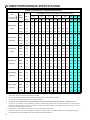
BLOWER PERFORMANCE SPECIFICATIONS
BLOWER PERFORMANCE
(CFM & Temperature Rise vs. External Static Pressure)
(
EXTERNAL STATIC PRESSURE (Inches Water Column)
Tons AC
Model
)
Heating Speed
As Shipped
Motor
Speed
at 0.5"
ESP
0.1
0.2
0.3
0.4
0.5
0.6
0.7
0.8
CFM RISE CFM RISE CFM RISE CFM RISE CFM RISE CFM CFM CFM
HIGH
3.0
1352
---
1318
---
1260
---
1202
---
1128
---
1044
955
853
GKS90453BX*
MED
2.5
1214
---
1172
---
1123
---
1064
---
1012
---
938
859
741
(LOW)
MED-LO
2.0
997
---
994
---
960
35
923
36
884
38
817
741
611
LOW
1.5
757
44
753
44
734
45
704
47
674
49
620
524
438
HIGH
3.0
1449
36
1409
37
1326
39
1273
41
1201
43
1194 1136 1018
GKS90703BX*
MED
2.5
1192
43
1172
44
1141
45
1094
47
1046
49
973
904
793
(MED-HI)
MED-LO
2.0
981
53
962
54
943
55
917
56
888
58
830
764
665
LOW
1.5
750
---
730
---
714
---
692
---
657
---
620
570
502
HIGH
4.0
2069
---
1965
---
1871
---
1756
---
1661
---
1549 1415 1275
GKS90704CX*
MED
3.5
1752
---
1724
---
1667
---
1603
---
1488
35
1402 1290 1082
(LOW)
MED-LO
3.0
1437
36
1437
36
1417
36
1369
38
1320
39
1256 1140
984
LOW
2.5
1184
44
1177
44
1161
44
1132
46
1095
47
1047
837
HIGH
4.0
1970
---
1874
35
1757
38
1667
40
1566
42
1431 1334 1182
GKS90904CX*
MED
3.5
1713
39
1650
40
1572
42
1510
44
1418
47
1313 1211 1079
(MED-LO)
MED-LO
3.0
1439
46
1412
47
1370
48
1327
50
1260
53
1166 1078
956
LOW
2.5
1183
56
1155
57
1122
59
1108
60
1062
62
1011
816
HIGH
5.0
2147
---
2114
---
2057
---
2030
---
1978
---
1889 1784 1713
GKS90905DX*
MED
4.0
1675
40
1686
---
1640
40
1623
41
1557
43
1501 1455 1360
(MED-LO)
MED-LO
3.5
1489
45
1470
45
1436
46
1409
47
1361
49
1318 1243 1130
LOW
3.0
1307
51
1265
52
1234
54
1203
55
1168
57
1096 1053
HIGH
5.0
2134
40
2103
40
2029
42
1941
44
1906
44
1818 1733 1625
GKS91155DX*
MED
4.0
1678
51
1643
52
1643
52
1577
54
1527
56
1489 1423 1339
(MED-HI)
MED-LO
3.5
1453
58
1440
59
1426
59
1363
62
1349
63
1314 1253 1205
LOW
3.0
1259
67
1239
68
1220
70
1181
---
1159
---
1118 1082 1015
928
931
991
1.
CFM in chart is without filters(s). Filters do not ship with this furnace, but must be provided by the installer. If the furnace requires two
return filters, this chart assumes both filters are installed.
2.
All furnaces ship as high speed cooling. Installer must adjust blower cooling speed as needed.
3.
For most jobs, about 400 CFM per ton when cooling is desirable.
4.
INSTALLATION IS TO BE ADJUSTED TO OBTAIN TEMPERATURE RISE WITHIN THE RANGE SPECIFIED ON THE RATING PLATE.
5.
The chart is for information only. For satisfactory operation, external static pressure must not exceed value shown on rating plate. The
shaded area indicates ranges in excess of maximum external static pressure allowed when heating. The data for 0.6" w.c. to 0.8" w.c.
is shown for air conditioning purposes only.
6
The dashed (---) areas indicate a temperature rise not recommended for this model.
7.
The above chart is for U.S. furnaces installed at 0-4000 feet. At higher altitudes, a properly derated unit will have approximately the
same temperature rise at a particular CFM, while the ESP at that CFM will be lower.
12
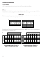
TEMPERATURE RISE
10
20
30
40
50
60
70
30
80
90
100
40
50
60
700
600 CFM
90
100
2000
2200
2400 CFM
1800
1600
1400
OUTPUT BTU/HR x 1000
80
1200
1100
1000
900
70
800
FORMULAS
110
120
130
140
BTU OUTPUT = CFM x 1.08 x RISE
BTU OUTPUT
RISE =
÷ CFM
1.08
BTU OUTPUT vs TEMPERATURE RISE CHART
150
BLOWER PERFORMANCE SPECIFICATIONS
13
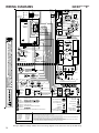
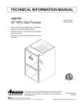
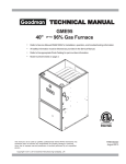
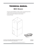
WIRING DIAGRAMS
GKS9*****X**
BLOWER
COMPARTMENT
DOOR SWITCH
(OPEN WHEN
DOOR OPEN)
OR
24 VAC
HUMIDIFIER
GY
24 VAC
INTEGRATED
CONTROL MODULE
HUMIDIFIER
TR (6)
GND
GND (8)
C2
MVC (9)
115 VAC
24V THERMOSTAT
CONNECTIONS
C
R
G
GAS
VALVE
N
O
BK
BL
INTEGRATED
CONTROL
MODULE
GY
3
2
1
6
5
4
PK
OR
9
8
7
BL
12
11
10
YL
GR
OR
GY
24V THERMOSTAT CONNECTIONS
OR
FUSE
ID BLOWER
PRESSURE
SWITCH
OPTIONAL FRONT COVER
PRESSURE SWITCH
BK
WH
BK
C
MV(12)
C
W Y
M1
G
PS (10)
NO
C
PSO (4)
TO
MICRO
Y
HLI (7)
W
HLO (1)
R
RO2 (11)
RO1 (5)
BR
RD
TH (3)
24 VAC
2
115 VAC HOT AND PARK TERMINALS
COOL-H
WH
FS
HOT SURFACE
IGNITER
IGN
BK
GY
BR
BK
ID
BLWR
IND
CO
OL
CIRCULATOR
BLWR
-H
AT
HE
OR
MANUAL RESET
AUXILIARY LIMIT
IN UPFLOW
BLOWER DECK
CAPACITOR
OR
BL
WH
BR
GR
RD
WH
BR
PK
RD
YL
BK (HI)
BL (MED)
OR (MED LOW)
RD (LOW)
LINE NEUTRALS
INTEGRATED CONTROL MODULE
WH
INTEGRATED CONTROL MODULE
LINE-H
SEE
NOTE 4
115 VAC
FLAME SENSOR
1
HEAT-H
GND
XFMR-H
PK
DIAGNOSTIC
LED
115 VAC NEUTRAL
TERMINALS
XFMR-H
HIGH VOLTAGE!
DISCONNECT ALL POWER BEFORE SERVICING OR INSTALLING THIS
UNIT. MULTIPLE POWER SOURCES MAY BE PRESENT. FAILURE TO
DO SO MAY CAUSE PROPERTY DAMAGE, PERSONAL INJURY OR DEATH.
40 VA
TRANSFORMER
WH
PU
BLOWER COMPARTMENT
BURNER COMPARTMENT
LINE-H
JUNCTION BOX
GND
DOOR
SWITCH
BK
WH
WH
INDUCED DRAFT
BLOWER
DISCONNECT
WH
PU
BL
L
YL
RD
N
O
GND
N
TO 115VAC/ 1Ø /60 HZ POWER SUPPLY WITH
OR
OR
OVERCURRENT PROTECTION DEVICE
C
PK
RD
WH
ID BLOWER
24 VAC
PRESSURE
HUMIDIFIER
SWITCH
2 CIRCUIT
CONNECTOR
C2
BL
GND
WH
MI
GY
OPTIONAL FRONT COVER
PRESSURE SWITCH
STEADY ON = NORMAL OPERATION
BK
LOW VOLTAGE (24V)
= CONTROL FAILURE
1
1 FLASH
=
2
2 FLASHES = PRESSURE SWITCH STUCK CLOSED
HI VOLTAGE (115V)
HI VOLTAGE FIELD
LOW VOLTAGE FIELD
3
3 FLASHES = PRESSURE SWITCH STUCK OPEN
4
4 FLASHES = OPEN HIGH LIMIT
5
5 FLASHES = FLAME SENSE WITHOUT GAS VALVE
6
6 FLASHES =
C
CONTINUOUS/RAPID FLASHES = REVERSED 115 VAC POLARITY
EQUIPMENT GND
FIELD GND
FIELD SPLICE
SWITCH (TEMP.)
JUNCTION
TERMINAL
INTERNAL TO
INTEGRATED CONTROL
PLUG CONNECTION
PK PINK
BR BROWN
WH WHITE
BL BLUE
GY GRAY
RD RED
L
FLAME
SENSOR
OFF
COLOR CODES:
YL YELLOW
OR ORANGE
PU PURPLE
GN GREEN
BK BLACK
N
GND
C
GAS VALVE
0
GR
BR
NO
HOT
SURFACE
IGNITER
JUNCTION
BOX
IGNITER
SWITCH (PRESS.)
OVERCURRENT
PROT. DEVICE
NOTES:
1. SET HEAT ANTICIPATOR ON ROOM THERMOSTAT AT 0.7 AMPS.
2. MANUFACTURER'S SPECIFIED REPLACEMENT PARTS MUST BE USED WHEN SERVICING.
3. IF ANY OF THE ORIGINAL WIRE AS SUPPLIED WITH THE FURNACE MUST BE REPLACED, IT MUST BE REPLACED WITH WIRING MATERIAL
HAVING A TEMPERATURE RATING OF AT LEAST 105 °C. USE COPPER CONDUCTORS ONLY.
4. IF HEATING AND COOLING BLOWER SPEEDS ARE NOT THE SAME, DISCARD JUMPER BEFORE CONNECTING BLOWER LEADS. UNUSED
BLOWER LEADS MUST BE PLACED ON "PARK" TERMINALS OF INTEGRATED CONTROL OR TAPED.
5. UNIT MUST BE PERMANENTLY GROUNDED AND CONFORM TO N.E.C. AND LOCAL CODES.
0140F00236 REV. D
Wiring is subject to change. Always refer to the wiring diagram on the unit for the most up-to-date wiring.
14