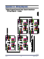
1
Installation Manual Trident Precast Concrete Deck Truck Scale © 2011 by Fairbanks Scales, Inc. All rights reserved. Revision 2 51255 04/11 Amendment Record TRIDENT PRECAST CONCRETE DECK TRUCK SCALE Document 51255 Manufactured by Fairbanks Scales, Inc. 821 Locust St. Kansas City, Missouri 64106 Created 12/10 Created document Revision 1 01/11 Document release Revision 2 04/11 Revised section 3 04/11 3 51255 Rev. 2 Disclaimer Every effort has been made to provide complete and accurate information in this manual. However, although this manual may include a specifically identified warranty notice for the product, Fairbanks Scales makes no representations or warranties with respect to the contents of this manual, and reserves the right to make changes to this manual without notice when and as improvements are made. Fairbanks Scales shall not be liable for any loss, damage, cost of repairs, incidental or consequential damages of any kind, whether or not based on express or implied warranty, contract, negligence, or strict liability arising in connection with the design, development, installation, or use of the scale. © Copyright 2011 This document contains proprietary information protected by copyright. All rights are reserved; no part of this manual may be reproduced, copied, translated or transmitted in any form or by any means without prior written permission of the manufacturer. 04/11 4 51255 Rev. 2 Table of Contents SECTION 1: GENERAL INFORMATION . . . . . . . . . . . . . . . . . . . . . . . . . . . . . . . . Introduction . . . . . . . . . . . . . . . . . . . . . . . . . . . . . . . . . . . . . . . . . . . . . . . . . . . . . . . . Description . . . . . . . . . . . . . . . . . . . . . . . . . . . . . . . . . . . . . . . . . . . . . . . . . . . . . . . . . CERTIFICATIONS . . . . . . . . . . . . . . . . . . . . . . . . . . . . . . . . . . . . . . . . . . . . . . . . . . . . SECTION 2: COMPANY SERVICE INFORMATION . . . . . . . . . . . . . . . . . . . . . . . General Service Policy . . . . . . . . . . . . . . . . . . . . . . . . . . . . . . . . . . . . . . . . . . . . . . . . Overview . . . . . . . . . . . . . . . . . . . . . . . . . . . . . . . . . . . . . . . . . . . . . . . . . . . . . . . . . . Physical Installation Notes . . . . . . . . . . . . . . . . . . . . . . . . . . . . . . . . . . . . . . . . . . . . . Conferring with our Client . . . . . . . . . . . . . . . . . . . . . . . . . . . . . . . . . . . . . . . . . . . . . . Pre-Installation Checklist . . . . . . . . . . . . . . . . . . . . . . . . . . . . . . . . . . . . . . . . . . . . . . Unpacking . . . . . . . . . . . . . . . . . . . . . . . . . . . . . . . . . . . . . . . . . . . . . . . . . . . . . . . . Equipment Checkout . . . . . . . . . . . . . . . . . . . . . . . . . . . . . . . . . . . . . . . . . . . . . . . . Users’ Responsibility . . . . . . . . . . . . . . . . . . . . . . . . . . . . . . . . . . . . . . . . . . . . . . . . SECTION 3: SCALE INSTALLATION . . . . . . . . . . . . . . . . . . . . . . . . . . . . . . . . . . A. Introduction . . . . . . . . . . . . . . . . . . . . . . . . . . . . . . . . . . . . . . . . . . . . . . . . . . . B. Tools, equipment and materials required . . . . . . . . . . . . . . . . . . . . . . . . . . . . . . . . C. Determine if product is cover plated model or undermount model . . . . . . . . . . . . . . . D. Foundation . . . . . . . . . . . . . . . . . . . . . . . . . . . . . . . . . . . . . . . . . . . . . . . . . . . . E. Setting the Center Module . . . . . . . . . . . . . . . . . . . . . . . . . . . . . . . . . . . . . . . . . . F. Setting end modules . . . . . . . . . . . . . . . . . . . . . . . . . . . . . . . . . . . . . . . . . . . . . . G. Connecting the Modules . . . . . . . . . . . . . . . . . . . . . . . . . . . . . . . . . . . . . . . . . . . H. Installing load cells . . . . . . . . . . . . . . . . . . . . . . . . . . . . . . . . . . . . . . . . . . . . . . . I. Final checking adjustment . . . . . . . . . . . . . . . . . . . . . . . . . . . . . . . . . . . . . . . . . . SECTION 4: ELECTRICAL INSTALLATION . . . . . . . . . . . . . . . . . . . . . . . . . . . . SECTION 5: MAINTENANCE . . . . . . . . . . . . . . . . . . . . . . . . . . . . . . . . . . . . . . . . Scale Maintenance . . . . . . . . . . . . . . . . . . . . . . . . . . . . . . . . . . . . . . . . . . . . . . . . . Mechanical Faults . . . . . . . . . . . . . . . . . . . . . . . . . . . . . . . . . . . . . . . . . . . . . . . . . . SECTION 6: PARTS & PARTS REPLACEMENT . . . . . . . . . . . . . . . . . . . . . . . . Parts List . . . . . . . . . . . . . . . . . . . . . . . . . . . . . . . . . . . . . . . . . . . . . . . . . . . . . . . . Load cells and load cell hardware . . . . . . . . . . . . . . . . . . . . . . . . . . . . . . . . . . . . . . . “O” Rings . . . . . . . . . . . . . . . . . . . . . . . . . . . . . . . . . . . . . . . . . . . . . . . . . . . . . . . . Replacing an RC load cell . . . . . . . . . . . . . . . . . . . . . . . . . . . . . . . . . . . . . . . . . . . . . General load cell information . . . . . . . . . . . . . . . . . . . . . . . . . . . . . . . . . . . . . . . . . . SECTION 7: ACCESSORIES . . . . . . . . . . . . . . . . . . . . . . . . . . . . . . . . . . . . . . . . . Rub Rails – These accessories are available in factory-installed and field-installed types . . . APPENDIX I: FOUNDATION CHECKLIST . . . . . . . . . . . . . . . . . . . . . . . . . . . . . APPENDIX II: SPECIFICATIONS . . . . . . . . . . . . . . . . . . . . . . . . . . . . . . . . . . . . . Trident Precast Concrete Deck . . . . . . . . . . . . . . . . . . . . . . . . . . . . . . . . . . . . . . . . . APPENDIX III: WIRING DIAGRAMS . . . . . . . . . . . . . . . . . . . . . . . . . . . . . . . . . . Trident Precast Concrete Deck Typical Installation Wiring Diagram – Analog . . . . . . . . . . Trident Precast Concrete Deck Typical Installation Wiring Diagram – Intalogix 04/11 5 ......... 6 6 6 6 7 7 8 8 8 9 9 10 10 11 11 11 12 14 15 16 18 21 24 25 29 29 29 30 30 31 32 33 33 34 34 35 37 37 38 38 39 51255 Rev. 2 Section 1: General Information INTRODUCTION This manual provides installation instructions for the Fairbanks Trident Precast Concrete Deck Truck Scale. For complete Trident scale installation, use: • Methods and Procedures FF-2267 / 101732 (Appendix I) • The certified prints/setting plans supplied with the scale • This installation manual, 51255 The concrete foundation work must be performed according to the certified prints issued for the specific customer and order number. (The name and order number for the particular customer will be on the prints.) NOTE: It is the owner's responsibility to document, notify, and follow-up regarding shipping damage with the carrier. DESCRIPTION The factory poured truck scales are available in various lengths and widths. The scale is made up of modules of 10', 15', 20' or 23'4" in length. All modules are assembled and welded at the factory. The concrete deck is mixed, poured, placed, finished, and cured at the factory. The scale should be located so that vehicles can approach and exit the scale as easily as possible. The platform should be visible from the instrument location. Drainage of surface water must be such that water does not collect under the scale. Smooth and level approaches are required at each end of the platform to reduce loading shock and facilitate testing of the scale. Approaches must conform to the requirements of the law in the state in which the scale is being installed. In the absence of such laws the approaches must conform to paragraph UR.2.6 National Institute of Standards and Technology Handbook 44, which states that the first 10 feet must be level and on the same plane as the scale platform. NOTE: Specifications and sizes are shown in Appendix II. CERTIFICATIONS NTEP CC: 96-089A3 04/11 MC: AM - 4949 6 51255 Rev. 2 Section 2: Company Service Information GENERAL SERVICE POLICY Prior to installation, alw ays verify that the equipment satisfies the customer's requirements as supplied, and as described in this manual. If the equipment cannot satisfy the application and the application cannot be modified to meet the design parameters of the equipment, the installation should NOT be attempted. It is the customer/operator's responsibility to ensure the equipment provided by Fairbanks is operated within the parameters of the equipment's specifications and protected from accidental or malicious damage. W A R N I N G Absolutely NO physical, electrical, or program modifications (other than selection of standard options and accessories) may be made to this equipment by customers. Repairs must be performed by Fairbanks Scales service technicians and authorized distributor personnel ONLY! Failure to comply with this policy voids all implied and/or written warranties. 04/11 7 51255 Rev. 2 Section 2: Company Service Information OVERVIEW Physical I nstallation Notes • Check all devices for proper operation. If any error messages occur, refer to Troubleshooting or the proper manual of that device. • Only those charges w hich are incurred as a result of the equipment's inability to be adjusted to performance specifications may be charged to w arranty. • No physical alterations (mounting holes, etc.) are allowed during installation. The installing technician is responsible that all personnel are fully trained and fam iliar w ith the equipm ent's capabilities and lim itations before the installation is considered com plete. • All electrical assemblies must be replaced as assemblies or units. ─ Replacement of individual components is not allowed. ─ These components must be returned intact for replacement credit per normal procedures. • All electronic and mechanical adjustments are considered to be part of the installation, and are included in the installation charge(s). ─ Included is any required computer programming or upgrades. ─ Included are any accuracy and/or operational specification changes. • The AC receptacle / outlet shall be located near the Instrument and easily accessible. • Electrical connections other than those specified may not be performed. Conferring w ith our Client • The technician must be prepared to recommend the arrangement of components which provide the most efficient layout, utilizing the equipment to the best possible advantage. • The warranty policy must be explained and reviewed with the customer. 04/11 8 51255 Rev. 2 Section 2: Company Service Information Pre-I nstallation Checklist The following points should be checked and discussed with the Area Sales Manager and/or customer, if necessary, before the technician goes to the site and installs the equipment. Check the customer's application to make certain it is within the capabilities and design parameters of the equipment. If the installation process might disrupt normal business operations, tell the customer and ask that they make adequate arrangements. Be sure that the equipment operator(s) are available for training. The service technician reviews the recommended setup with the Area Sales Manager or Area Service Manager, and together they identify all necessary variations to satisfy the customer's particular application. Unpack ing Follow these guidelines when unpacking all equipment: Check in all components and accessories according to the customer's order. Remove all components from their packing material, checking against the invoice that they are accounted for and not damaged. Advise the shipper immediately, if damage has occurred. Order any parts necessary to replace those which have been damaged. Keep the shipping container and packing material for future use. Check the packing list. Collect all necessary installation manuals for the equipment and accessories. Open the equipment and perform an inspection, making certain that all hardware, electrical connections and printed circuit assemblies are secure. Do not reinstall the cover if the final installation is to be performed after the pre-installation checkout. 04/11 9 51255 Rev. 2 Section 2: Company Service Information Equipm ent Checkout Position the equipment with these points in mind: Intense direct sunlight can harm the display. Do not locate near magnetic material or equipment/Instruments which use magnets in their design. Avoid areas which have extreme variations in room temperatures. Temperatures outside the Instrument’s specifications will affect the weighing accuracy of this product. Do not load the platform if there is any evidence of damage to the platform or supporting structure. Users’ R esponsibility All electronic and mechanical calibrations and/or adjustments required for making this equipment perform to accuracy and operational specifications are considered to be part of the installation. ─ They are included in the installation charge. ─ Only those charges which are incurred as a result of the equipment's inability to be adjusted or calibrated to performance specifications may be charged to warranty. Absolutely no physical, electrical, or program modifications other than selection of standard options and accessories are to be made to this equipment. The equipment consists of printed circuit assemblies which must be handled using ESD handling procedures, and must be replaced as units. ─ Replacement of individual components is not allowed. ─ The assemblies must be properly packaged in ESD protective material and returned intact for replacement credit per normal procedures. 04/11 10 51255 Rev. 2 Section 3: Scale Installation A. I ntroduction Installation consists of the following: • • • • Foundation check, layout, and base plate setting Tools, materials, documentation, and a crane Setting the modules Setting the modules on load cells B. Tools, equipm ent and m aterials required 1. Certified prints 2. A mobile crane of sufficient capacity to safely lift and place the weigh bridge modules. Approximate maximum weights: Factory poured modules – 14,500 lbs., 7.2 tons, ±5% for 23’ x 10’ module without rub rails. 3. Four (4) equal length (20 ft) lifting chains or cables with hooks to safely attach to the modules at the lifting points. Note: The lifting chains or cables MUST be requested in advance from the crane vendor. 4. Machinist’s levels (Starrett 134 and 132-6) 5. Hand tools 6. Hammer drill with ⅝” bit, 24” 7. Hydraulic jacks -- Use a safety factor for the • 96496 • 96497 • 96498 hydraulic jacks that have sufficient capacity plus (+) model of scale you are installing. 30 ton jacks Hand pump Hose, 6’ 8. 100' steel tape measure 9. String line and / or chalk line 10. Pry bars 11. Grease and anti-seize 12. Load cell locating tools, one for each load cell, • Part no. 71717 for 5½" 04/11 11 51255 Rev. 2 Section 3: Scale Installation C. Determ ine if product is cover plated m odel or underm ount m odel. The profile of the cover plated model has unique details and looks like this. COVER PLATE MODEL – Locating tool detail 04/11 12 51255-1 51255 Rev. 2 Section 3: Scale Installation The undermount model looks like this. UNDERMOUNT MODEL – Locating tool detail 04/11 13 51255-2 51255 Rev. 2 Section 3: Scale Installation D. Foundation Before installing any part of the scale, the foundation must be checked for accuracy using Foundation Inspection, Field Check List, FF-2267 / 101732 (see Appendix I). a. Layout and position the base plates in the proper locations using the Methods & Procedures and Certified prints. Each base plate must be level and in full contact with the top of the pier. Adjustments can be made by chipping the concrete or grouting under the base plates. b. Re-check the locations of each base plate against the certified prints. • Insert two ½" roll pins into each lower cup for anti-rotation. c. Grease and install the inner "O" ring in each load cell cup if they are not already installed. On all cups, grease the large outer "O" rings, then install one in the groove on the outside of each cup. Put a 3/16" shim on the lower cups, grease the outsides, and insert them into the base plates. Lower cups for 5½" load cells have a pin which must be aligned between the two roll pins in the base plate. d. Place the upper cup with greased "O" ring on the edge of the upper foundation next to each base plate. e. Place the load cell locating tool next to each base plate. A. Setting the modules - Preparing the modules for lifting • • The modules do not have integrated lifting channels. One (1) set of lifting eye bolts (threaded eye bolts) is provided by Fairbanks. Thread and bolt lifting eye bolts at each corner of the module for proper lifting. WARNING! Lift only as shown in drawing below on left side. NEVER with a fork lift beneath the panel! Lift ONLY as shown below! 04/11 Do NOT lift panels with a fork lift! 14 51255 Rev. 2 Section 3: Scale Installation E. Setting the Center M odule The center module is always set first. The center module will have four load cells to install, all other modules will have two load cells. The modules must be placed in the proper order and aligned in the foundation so that all modules fit correctly. • Undermount scales have a definite orientation because the junction box mounting bars are welded to one (1) side only. The j-box side of the modules should face the home-run conduit. a. Place blocks that will set the modules at a height slightly less than the finished height as safety blocks, or for setting the modules on. b. Lift the center module to a location above the four center load cell base plates. Install a load cell bearing cup with "O" rings into the upper receiver of each corner, grease will help hold the cup in place. Insert the upper end of the locating tool into the upper cup on the module. Set the module directly on the locating tools and the blocks will act as safety stands. Lower the module while holding the locating tool upright and guiding the bottom of the tool into the lower cup. When the center module is set on all four locating tools, keep tension on the cables until the module is centered and straight. Once square and plumb are verified, you can release tension slowly. Use hydraulic jacks to lift the unit slightly and shift the base plates to get the locating tools plumb and the top and bottom flanges FLUSH with the sides of the cup. c. Measure from each side of each end of the module, to the end walls, to be certain the module is plumb and square before removing tension. d. Remove threaded eye bolts and install on next module for proper lifting. 04/11 15 51255 Rev. 2 Section 3: Scale Installation F. Setting end m odules For undermount model: • Module Placement: Guide the modules into place with the supporting blocks on the end of the module coming to rest on the supporting blocks of the center module. Lower the other end of the module onto the load cell locating tools or blocks. (See Figure 51255-3). a. Before releasing tension on the cables, check the alignment of the end modules to the center module and to the end wall. • Use the provided shims to set height and fill any gaps on the supporting blocks to get the modules aligned. b. Repeat this process for the other end module or for the interior module. Undermount model panel block detail 04/11 51255-3 16 51255 Rev. 2 Section 3: Scale Installation For cover plated model: a. Install interlocking pin into hole on top of the load block of the panel already resting on locating tools. b. Guide the modules into place with the deck seats on the end of the module coming to rest on the center module load block interlocking pins. Lower the other end of the module onto the load cell locating tools or blocks. b. Before releasing tension on the cables, check the alignment of the end modules to the center module and to the end wall. 51255-4 Cover plate model panel block detail 04/11 17 51255 Rev. 2 Section 3: Scale Installation G. Connecting the M odules: For undermount model: a. Bolt the modules together using the 1-⅛" x 7" full-thread rod, lock washer, flat washers and nut provided. Remember to shim the supporting blocks if necessary to align modules. Snug nuts, but do not fully tighten them yet. (See Figure 51255-5.) 1 1/8” Undermount model panel connection detail 51255-5 For cover plate model: c. Bolt the modules’ channels together using the ½” x 4” x 6” spacers and 1” x 3” bolts. Insert the ½” x 4” x 6” spacer plates between the channels. The bolts go through the back-to-back channels and the spacer. Snug the bolts but do not tighten them yet. (See Figure 51255-6.) Cover plate model panel connection detail 04/11 18 51255-6 51255 Rev. 2 Section 3: Scale Installation * * Warning * * Module-to module bolts MUST be installed correctly and with proper torque after all lifting, etc., is completed. Do NOT substitute or omit bolts. B. Checking Adjustment (see Figures 51255-7 through 51255-10). For undermount model: a. Adjust end checking -- Adjust the end checking bolts so that they touch and prevent movement. (See figure 51255-7) b. Install the side checking brackets -- Bolt the brackets to the end checking plates embedded in the end walls per certified prints. Set the bolts so that they touch the block they bump against. (See figure 51255-8.) 04/11 Undermount end checking detail 51255-7 Undermount side checking detail 51255-8 19 51255 Rev. 2 Section 3: Scale Installation For cover plate model: • Install the side checking brackets: • Bolt the brackets into the end copings per the certified drawings. • Set the side checking bolts so they touch the channels they bump against. Cover plated side and end checking 51255-9 Base plate completion • Check that all locating tools are properly aligned and flush with the receiver cups. Drill the holes for the base plate anchors using a hammer drill and the ⅝” drill bit. Tap the anchors into clean holes and tighten the nuts securely. 04/11 20 51255 Rev. 2 Section 3: Scale Installation H. I nstalling load cells a. Unpack the load cells and mark each calibration certificate with the load cell location/position. * * WARNING * * Place hydraulic jacks ONLY at the CORNERS of the modules. Hydraulic jacks must be placed on opposite sides to lift the module in a level position. Lifting mid-span or between load cells will cause cracks in the concrete! b. Starting at one end of the assembled platform, place hydraulic jacks at the corners so the section can be lifted off the locating tool. Two (2) hydraulic jacks may be required. c. Lift the platform so the load cell locating tool can be removed from the upper and lower bearing cups. Once removed, fill both cups with grease. d. The bottom of the load cell has two flat sides which must be aligned with the flats in the lower cup. Carefully lower the scale (hydraulic jacks) while seating the bottom of the cell into the lower cup. Check the scale’s level and height, particularly at the approaches. Use the load cell shims provided to adjust load cell cups for correct height and to ensure that all cells share an equal amount of the load. Center section cells will have up to twice the dead load of end section cells. Caution – Use eye protection! e. Once satisfied with height and level, tighten the module-to-module bolts. • The nuts should be torque to 500 ft. lbs. f. Load cell cables 04/11 • Introduction: Cable protection on truck scales is extremely important to the reliability of the scale. It is imperative for all cables to be installed off the ground, and out of sight. The Trident truck scale has been designed to accommodate this type of cable protection. Described in this section is the manufacturer’s recommended installation procedure for installing and protecting cables on the Trident truck scale. • Cable hangers: Behind every SSC or PPS mounting block is a cable hanger. These cable hangers are used to hang excess load cell and interconnecting cables. 21 51255 Rev. 2 Section 3: Scale Installation • Complete installation: Once all cables have been run and wiring is complete (See section 4), tighten all the cables and hang them on the cable hangers to get them out of sight and off the ground. In a correct installation, the only cables visible are those coming out of the holes in the side beam to the SSC or PPS. See photo below: Undermount model: Undermount model 04/11 51255-10 22 51255 Rev. 2 Section 3: Scale Installation Cover plate model: Cover plated model 51255-11 NOTE: All Tridents come standard with Intalogix. If the analog model is ordered (Box 21912) mount as follows: Balance box 21912 – Installation for analog instruments 1. Introduction – Balance box 21912 is to be installed at the platform, one box per section. 2. Description – Each stainless steel balance box has four (4) terminal blocks to connect two (2) load cells and two (2) cables for connection to the analog instrument. Load cells and sections are adjusted using adjusting potentiometers. 3. Installation – a. Boxes: The box has tabs for bolting to mounting brackets on the side of the modules. (See figure 51255-10.) or if cover plated, under each sectional cover plate (See figure 51255-11.) Attach the ground wire lug to one of the mounting bolt studs and tighten securely to provide a good electrical ground. b. Wiring: Cable used in all wiring must be a minimum of 18 AWG. Use cable 17204 or equivalent. The balance boxes are interconnected from TB1 to TB2 or TB2 to TB2 beginning at the end section where the interface cable conduit enters the scale. An alternate method, if the conduit enters the scale in the middle, is to use 14478 instrument SVP. This will allow separate connections to go in each direction toward the ends of the scale. See bulletin 50513 for the wiring diagrams. 04/11 23 51255 Rev. 2 Section 3: Scale Installation I . Final checking adjustm ent a. Adjust end checking • Adjust the end checking bolts to 1/16” to ⅛” clearance. b. Adjust side checking bolts to allow 1/16” clearance from bumper block. 04/11 24 51255 Rev. 2 Section 4: Electrical Installation A. Load cell wiring color codes 5¼” RC 30t (66,000 lbs.) Load Cell (part no 70510) LCF-HR4020-2A Black Green Red White Yellow (-) Excitation (+) Excitation (-) Signal (+) Signal Shield B. Wiring – 21912 Analog Junction Box Cells to J-Box 21912 – 1 box per section Position TB3 BLACK (-) EXC 1 GREEN (+) EXC 2 (+) SENSE 3 (-) SENSE 4 N/C 5 YELLOW SHIELD 6 WHITE (+) SIG 7 RED (-) SIG 8 J-Box to J-Box Position BLACK 1 GREEN 2 BLUE 3 ORANGE 4 N/C 5 SHIELD 6 WHITE 7 RED 8 TB1 or TB2 (-) EXC (+) EXC (+) SENSE (-) SENSE N/C SHIELD (+) SIG (-) SIG Instrument to J-Box Position 1 2 3 4 6 7 8 TB1 or TB2 (-) EXC (+) EXC (+) SENSE (-) SENSE SHIELD (+) SIG (-) SIG 04/11 25 TB4 (-) EXC (+) EXC (+) SENSE (-) SENSE N/C SHIELD (+) SIG (-) SIG TO TB2 (second box) or TB1 (-) EXC (+) EXC (+) SENSE MUST BE (-) SENSE USED N/C SHIELD (+) SIG (-) SIG 51255 Rev. 2 Section 4: Installing Accessories Note: This truck scale has been designed to provide protection from the effects of moisture. The load cells have been calibrated with the cable attached, and therefore the cable should NOT be cut. The cable is connected directly to the balance box or SSC through a sealed bushing which MUST be tightened properly to keep water/moisture out of the box. All cabling should have a drip loop at the cell or box entry location to help prevent water entry. On all boxes, particularly stainless steel, the black plastic fittings have “O” rings that can be forced out of position if the bushing itself is not tight. To prevent this, first tighten the inner nut securing the bushing in the hole, then insert cable and carefully tighten the gland until it is very snug. Do not over-tighten where bushing turns. Secure the cover. Note: Balance boxes must have one (1) ground rod in the pit for proper grounding. CAUTION Inadequate grounding will prevent the surge voltage protection from functioning properly. 1. Instrument cable connection, balance box The two (2) cables from the two (2) center section boxes will enter the 14478 instrument SVP and terminate there. The cable from the instrument will connect at 14478 instrument SVP as well. Prepare the cable ends in the standard manner. Use Appendix II for wiring instructions of all pit balance boxes. Connect the instrument interface cable to the instrument in the scale house per the instructions in the appropriate instrument service manual. 2. Adjusting cells/sections Try to install load cells of matching outputs in sections to reduce side-to-side errors. When calibrating, place weights directly over the cell or directly on the section being tested. Adjust the potentiometers for the correct cell or section to compensate for differences. 04/11 26 51255 Rev. 2 Section 4: Installing Accessories C. Wiring SSCs and PPSs for IntalogixTM systems 1. Introduction IntalogixTM systems utilize smart sectional controllers (SSCs) and pit power supplies (PPSes) for load cell excitation and signal processing. 2. Description There is one (1) SSC per section and one (1) PPS for the entire platform unless the number and resistance of the cells require a second pit power supply. SSC boxes have four (4) terminals, two (2) for load cells, and two (2) for interconnecting to other SSC boxes or terminating to a pit power supply. All cell, section, and scale adjustments are made via the IntalogixTM system instrument. 3. Installation a. Boxes – The box has tabs for bolting to adapters as shown in “Installing load cells.” b. Wiring – Cable used in all wiring must be a minimum of 18 AWG. Use cable 17204 or 17246. Use appropriate service manual for the instrument being installed, or use Appendix III to connect PPSes and SSCs. D. Smart Sectional Controller Wire cells into each section’s SSC per the appropriate manual. Remember that odd numbered cells go to TB1 location, and even numbered cells go to TB2 location. Load cell drain wires connect to the ground lug on the sectional controller box exterior. Note: IntalogixTM installations utilize a different numbering system for load cells because of digital addressing of the SSCs. Number the load cells as follows: With respect to the following starting position, face the platform from where the instrument is located. The cell at the upper left (far side) of the platform is Cell 1. The cell positions along the far side will be odd cell number, and the near side locations will be even cell numbers. Note: SSCs have connections for two (2) load cells, TB1 and TB2. The oddnumbered cell should go to the TB1 connection, and the even-numbered cell to the TB2 connection. 04/11 27 51255 Rev. 2 Section 4: Installing Accessories E. Grounding SSCs IntalogixTM systems must have two (2) ground rods in the pit for proper connection. Pit power supplies use a ground separate from the steel and SSC ground rod. F. Instrument-to-PPS cable connection Prepare the cable ends in the standard manner. Use the appropriate manual for wiring instructions of all pit SSCs and power supplies. Connect the instrument interface cable to the instrument in the in the scale house per the instructions in the appropriate indicator service manual. G. Wiring – Intalogix Junction Box 3. Cells to Smart Sectional Controller (SSC) Position 1 2 6 7 8 BLACK GREEN YELLOW WHITE RED TB1 (-) EXC (+) EXC SHIELD (+) /SIG (-) SIG TB2 (-) EXC (+) EXC SHIELD (+) /SIG (-) SIG 4. SSC to SSC or SSC to Pit Power Supply Position 1 2 5 6 7 8 BLACK GREEN BLUE SHIELD WHITE RED To TB3 (-) 8 VDC (+) 8 VDC DC RETURN SHIELD (+) RS485 (-) RS485 From TB4 (-) 8 VDC (+) 8 VDC DC RETURN SHIELD (+) RS485 (-) RS485 5. Pit Power Supply to instrument Position 1 2 3 4 6 7 8 04/11 BLACK GREEN BLUE ORANGE SHIELD WHITE RED TB1 (PPS) (-) 28 VAC (+) ACR (+) 20 VDC (-) ENABLE 5 VDC DC RETURN (+) RS485 (-) RS485 28 To TB1 (instrument) (-) 28 VAC (+) ACR (+) 20 VDC (-) ENABLE 5 VDC DC RETURN (+) RS485 (-) RS485 51255 Rev. 2 Section 5: Maintenance Scale M aintenance 1. Check for accumulations of solid material under the scale which may affect the accuracy (ice, frozen mud, debris). 2. Check to see that the customer has cleaned under the platform regularly. 3. Inspect load cells for damage to the ends/cables; check cups and “O” rings for damage. 4. The load cell bearing cups should be inspected, cleaned, and greased periodically. 5. Inspect and adjust all check bolts using anti-seize on the threads. M echanical Faults 1. Check for all clearances around the scale for any obstructions or interference with the free movement of the platform. 2. Check all check bolt clearances both with and without a concentrated load over each section, one at a time. 3. Check all load cells for plumb and level. 4. Inspect the boxes for leaks; the interior should be clean and dry. If there is moisture inside, clean and dry it thoroughly. Check all connections at the terminal blocks to ensure they are tight. 04/11 29 51255 Rev. 2 Section 6: Parts & Parts Replacement Parts List PART NO. DESCRIPTION 54511 ¾” – 10 x 1½” hex bolt for cover plate model only 63310 Interlocking pin – cover plate model only 64213 Bumper block – cover plate model only 64327 Load cell base plate – cover plate model only 61380 Side checking – cover plate model only 54304 Hex nut, 1⅛” – 7 – undermount model only 54891 Jam nut, 1⅛” – 7 – undermount model only 76708 1⅛”-7 x 8” threaded rod, zinc (module-module) – undermount model only 54788 1⅛” lock washer (module-module) – undermount model only 54255 1⅛” flat washer (module-module) – undermount model only 85593 Load cell base plate – undermount model only 75398 Side check bracket – undermount model only 61743 Clamp bar washer (base plates) 62857 ⅝” x 6” anchor bolts (wedge type) 55010 Dual ground rod kit 147922 Lifting eye bolt 54310 1¼” – 7 – hex nut for eye bolt 04/11 30 51255 Rev. 2 Section 6: Parts Load cells and load cell hardw are LCF-HR4020-2A - FLINTEC PART NO. DESCRIPTION 70510 Load cell, 5½” RC, 66k, 1000 Ω, 2 mV/V 72274 “O” ring, 5½” INSIDE of cup, *ANSI #222 64340 “O” ring, 5½” OUTSIDE of cup, *ANSI #228 70511 Receiver cup, 5½” LOWER (with anti-rotation pin) 70512 Receiver cup, 5½” UPPER 64382 Roll pin, ½” x 2½” anti-rotation, base plate 71717 Locating tool, 5½” (OPTIONAL) 64438 Shim, receiver cup, ⅛” 64334 Shim, receiver cup, 3/16” ANSI # NNN defines a standard “O” ring size. “O” rings may be obtained at any hardware, hydraulic, or plumbing supply house by using the number. 04/11 31 51255 Rev. 2 Section 6: Parts “O” R ings 2¼" I.D. 2½" O.D. Part No. 64340 ⅛" Thickness ANSI # 228 OUSIDE of all load cell cups 1½" I.D. 1¾" O.D. Part No. 72274 ⅛" Thickness ANSI # 222 INSIDE of cup 5½" load cells * * WARNING * * Lift scales ONLY at the CORNERS ! On factory pour scales, use two (2) properly rated hydraulic jacks at opposite sides, and at the corners, and lift the section in a level manner. 04/11 32 51255 Rev. 2 Section 6: Parts R eplacing an R C load cell 1. Remove power from the instrument. 2. Lift the scale using a proper sized and rated hydraulic jack (or jacks) at the corners closest to the defective load cell location * * WARNING * * Place hydraulic jacks ONLY at the CORNERS of the modules. Hydraulic jacks must be placed on opposite sides to lift the module in a level position. Lifting mid-span or between load cells will cause cracks in the concrete! Do NOT lift panels with a fork lift! 3. Check upper and lower receiving cups and “O” rings for damage. Replace as necessary and reapply grease. 4. Insert the new cell into the upper receiving cup and position the anti-rotation pin. 5. Carefully lower the hydraulic jack(s) until the cell is set into the lower cup. 6. Remove the cover of the SSC/J-box, then loosen the gland bushing to free the cable. Remove the old cell wires and connect new cell wires in the balance box/SSC. Secure the cover. 7. Test and adjust the scale as necessary. General load cell inform ation Load cell part number: 70510 Description: 5½” – 2mV/V, 66k or 30t, 1000 Ω 04/11 33 51255 Rev. 2 Section 7: Accessories R ub R ails – These accessories are available in factoryinstalled and field-installed types. Field-installed rub rail installation: • Use the print with the accessory for actual measurements. • Bolt the gussets to the stiffeners and end weldments. * * WARNING * * Fairbanks does NOT recommend using foundation-mounted guide rails along the sides of this truck scale platform. Damage may occur to the scale if a truck hits the guide rail, transferring damaging force to the platform and checking system. Use of this type guide rail will VOID PRODUCT WARRANTY. 04/11 34 51255 Rev. 2 Appendix I: Foundation checklist 100732 - Page 1 of 2 Trident 101732 04/11 12/10 – Issue 2 35 51255 Rev. 2 Appendix I: Foundation Checklist 100732 - Page 2 of 2 101732 04/11 12/10 – Issue 2 36 51255 Rev. 2 Appendix II: Specifications Trident Precast Concrete Deck 148010 Trident Precast, 10’ x 10’ – 50 ton capacity – 1 module, 2 sections 148011 Trident Precast, 10’ x 11’ – 50 ton capacity – 1 module, 2 sections 148015 Trident Precast, 15’ x 10’ – 50 ton capacity – 1 module, 2 sections 148016 Trident Precast, 15’ x 11’ – 50 ton capacity – 1 module, 2 sections 148020 Trident Precast, 20’ x 10’ – 50 ton capacity – 1 module, 2 sections 148021 Trident Precast, 20’ x 11’ – 50 ton capacity – 1 module, 2 sections 148023 Trident Precast, 23’ x 10’ – 50 ton capacity – 1 module, 2 sections 148024 Trident Precast, 23’ x 11’ – 50 ton capacity – 1 module, 2 sections 148030 Trident Precast, 30’ x 10’ – 75 ton capacity – 2 modules, 3 sections 148031 Trident Precast, 30’ x 11’ – 75 ton capacity – 2 modules, 3 sections 148040 Trident Precast, 40’ x 10’ – 75 ton capacity – 2 modules, 3 sections 148041 Trident Precast, 40’ x 11’ – 75 ton capacity – 2 modules, 3 sections 148047 Trident Precast, 47’ x 10’ – 75 ton capacity – 2 modules, 3 sections 148048 Trident Precast, 47’ x 11’ – 75 ton capacity – 2 modules, 3 sections 148060 Trident Precast, 60’ x 10’ – 100 ton capacity – 3 modules, 4 sections 148061 Trident Precast, 60’ x 11’ – 100 ton capacity – 3 modules, 4 sections 148070 Trident Precast, 70’ x 10’ – 100 ton capacity – 3 modules, 4 sections 148071 Trident Precast, 70’ x 11’ – 100 ton capacity – 3 modules, 4 sections 148080 Trident Precast, 80’ x 10’ – 125 ton capacity – 4 modules, 5 sections 148081 Trident Precast, 80’ x 11’ – 125 ton capacity – 4 modules, 5 sections 148090 Trident Precast, 90’ x 10’ – 125 ton capacity – 4 modules, 5 sections 148091 Trident Precast, 90’ x 11’ – 125 ton capacity – 4 modules, 5 sections 148100 Trident Precast, 100’ x 10’ – 125 ton capacity – 5 modules, 6 sections 148101 Trident Precast, 100’ x 11’ – 125 ton capacity – 5 modules, 6 sections 148110 Trident Precast, 110’ x 10’ – 125 ton capacity – 5 modules, 6 sections 148111 Trident Precast, 110’ x 11’ – 125 ton capacity – 5 modules, 6 sections 148120 Trident Precast, 120’ x 10’ – 125 ton capacity – 6 modules, 7 sections 148121 Trident Precast, 120’ x 11’ – 125 ton capacity – 6 modules, 7 sections 04/11 37 51255 Rev. 2 Appendix III: Wiring diagrams Trident Precast Concrete Deck Typical I nstallation W iring Diagram – Analog 51255-8 04/11 38 51255 Rev. 2 Appendix III: Wiring diagrams Trident Precast Concrete Deck Typical I nstallation W iring Diagram - I ntalogix 51255-9 04/11 39 51255 Rev. 2 Trident Precast Concrete Deck Truck Scale Manufactured by Fairbanks Scales, Inc. 821 Locust St. Kansas City, MO 64106 www.fairbanks.com INSTALLATION MANUAL DOCUMENT 51255