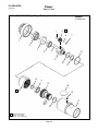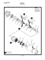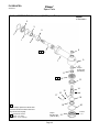
1
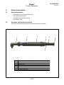
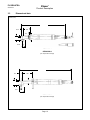
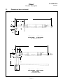
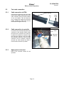
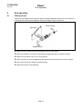
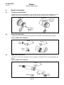
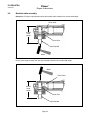
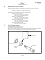
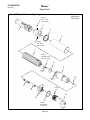
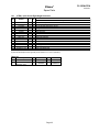
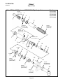
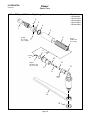
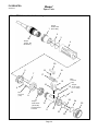
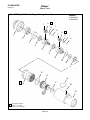
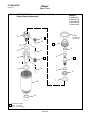
Service Manual PL12EN-67EA 06/04/2013 67EA Series Electronically Controlled Right Angle Nutrunner For additional product information visit our website at http://www.apextoolgroup.com PL12EN-67EA 06/04/2013 Cleco® General Information For this Instruction Manual This Instruction Manual is the Original Instruction Manual intended for all persons who will operate and maintain these tools. This Instruction Manual • provides important notes for the safe and efficient use of these tools. • describes the function and operation of the 67EA series tools. • serves as a reference guide for technical data, service intervals and spare parts ordering. • provides information on optional equipment. Identification text: 67EA represents all models of the DC electric right angle nutrunner as described in this manual Ú indicates a required action • indicates a list <..> indicates a reference number from the exploded parts drawings Arial indicates an important feature or instruction written in Arial Bold Identification graphic: ¢ ò indicates a directional movement indicates a function or force Copyright protection: Apex Tool Group, LLC reserves the right to modify, supplement or improve this document or the product without prior notice. This document may not be reproduced in any way, shape or form, in full or parts thereof, or copied to another natural or machine readable language or to a data carrier, whether electronic, mechanical, optical or otherwise without the express permission of Apex Tool Group, LLC. Page 2 PL12EN-67EA Cleco® 06/04/2013 Nomenclature 67 E Tool Series 67 Motor Style E = Brushless Electric Motor Tool Type A = Right Angle Maximum Torque Nm (rounded to nearest 5 Nm) 235 = 230 Nm 255 = 255 Nm 310 = 310 Nm 340 = 335 Nm 460 = 460 Nm 570 = 570 Nm 730 = 730 Nm 860 = 860 Nm 1035 = 1035 Nm 1340 = 1340 Nm 1700 = 1700 Nm 2010 = 2000 Nm Attachment AL6 = 3/4" Square Drive - Right Angle AM6 = 3/4" Square Drive - Right Angle ML6 = 3/4" Square Drive - Right Angle AH8 = 1" Square Drive - Right Angle Page 3 A XXXX XXX PL12EN-67EA 06/04/2013 Cleco® Contents 1 Safety 6 1.1 1.2 1.3 1.4 1.5 1.6 1.7 Warning and notes.................................................................................................. 6 Basic requirements for safe working practices....................................................... 6 Operator training..................................................................................................... 7 Personal protective equipment............................................................................... 7 Designated use....................................................................................................... 7 Codes and standards............................................................................................. 7 Noise and vibration................................................................................................. 7 2 Scope of supply, transport and storage 2.1 2.2 2.3 Items supplied........................................................................................................ 8 Transport................................................................................................................ 8 Storage................................................................................................................... 8 3 Product description 3.1 3.2 3.3 General description................................................................................................ 9 Operation and functional elements......................................................................... 9 Dimensional data.................................................................................................. 10 4 Accessories 12 5 Before initial operation 14 5.1 5.2 5.2.1 5.3 5.3.1 5.3.2 5.3.3 Ambient conditions............................................................................................... 14 Power supply........................................................................................................ 14 m-Pro-400GC series global controller.................................................................. 14 Tool cable connection........................................................................................... 15 Cable connection to 67EA.................................................................................... 15 Cable connection to controller.............................................................................. 15 Apply power to the tool......................................................................................... 15 6 First operation 6.1 Puting into use...................................................................................................... 16 7 Troubleshooting 17 8 Maintenance 18 8.1 8.1.1 8.2 Service schedule.................................................................................................. 18 Calculating a customer specific maintenance plan............................................... 19 Lubricants............................................................................................................. 19 8 9 16 Page 4 Cleco® PL12EN-67EA 06/04/2013 Contents 9 Repair instructions 20 9.1 9.2 9.3 9.4 9.5 9.6 9.7 Transducer identification....................................................................................... 20 Gear train lubrication............................................................................................ 20 Angle head lubrication.......................................................................................... 20 Throttle lever alignment........................................................................................ 21 Pinion gear setting (right angle attachments)....................................................... 21 Backlash shim assembly...................................................................................... 22 45019123 Adapter assembly................................................................................ 23 10 Spare parts 10.1 67EA(---)AL6 Series Right Angle Nutrunner......................................................... 24 10.2 67EA(---)AM6 Series and 67EA310ML6 Right Angle Nutrunner.......................... 26 10.3 67EA(----)AH8 Series Right Angle Nutrunner....................................................... 28 10.4 67EA Series Handle Assembly............................................................................. 30 10.5 67EA(---)AL6 Double Stage Gearing Assembly................................................... 32 10.6 67EA(---)AM6 Series and 67EA310ML6 Triple Stage Gearing............................ 34 10.7 67EA860AH8 Single Stage Gearing..................................................................... 36 10.8 67EA(----)AH8 Series Double Stage Gearing....................................................... 38 10.9 48056032 AL6 Attachment (3/4” Square Drive).................................................... 40 10.10 45037012 ML6 Attachment (3/4” Square Drive)................................................... 42 10.11 45017010 AL6 Attachment (3/4” Square Drive).................................................... 44 10.12.135A56033 AH8 Attachment (1/2” Square Drive ) Anle Head Assembly................ 46 10.12.235A56033 AH8 Attachment (1” Square Drive) Output Gearing Assembly............ 48 11 Technical data 50 11.1 67EA Specifications.............................................................................................. 50 12 Service 12.1 12.2 12.3 Replacement parts............................................................................................... 51 Tool repairs........................................................................................................... 51 Warranty repairs................................................................................................... 51 13 Disposal 51 52 Page 5 PL12EN-67EA 06/04/2013 Cleco® Safety 1 Safety 1.1 Warnings and notes Warning notes are identified by a signal word and a pictogram. • The signal word indicates the severity and probability of the impending danger. • The pictogram indicates the type of danger. --------------------------------------------------------------------------------------------------------------------------------------WARNING identifies a potentially hazardous situation which, if not avoided, may result in serious injury. ----------------------------------------------------------------------------------------------------------------------------------------------------------------------------------------------------------------------------------------------------------------------------CAUTION identifies a potentially hazardous situation which, if not avoided, may result in minor or moderate injury or property and environmental damage. ----------------------------------------------------------------------------------------------------------------------------------------------------------------------------------------------------------------------------------------------------------------------------NOTE identifies general information which may include application tips or useful information but no hazardous situations. ----------------------------------------------------------------------------------------------------------------------------------------------------------------------------------------------------------------------------------------------------------------------------Important information that must be read and understood by all personnel installing, operating or maintaining this equipment. 1.2 --------------------------------------------------------------------------------------------------------------------------------------- Basic requirements for safe working practices All personnel involved with the installation, operation or maintenance of these tools must read and understand all safety instructions contained in this manual. Failure to comply with these instructions could result in serious injury or property damage. These safety instructions are not intended to be all inclusive. Study and comply with all applicable National, State and Local regulations. --------------------------------------------------------------------------------------------------------------------------------------Work Area: Ú Ensure there is enough space in the work area. Ú Keep the work area clean. Ú Keep the work area well ventilated. Personnel Safety: Ú Inspect the power cable for damage. Make sure the power cable is securely attached to the tool. Ú Ú Ensure a secure standing position and maintain balance. Ú Make sure the throttle is positioned relative to the head so the throttle will not become wedged against an adjacent object in the ON position due to torque reaction. Ú If the tool is to be reversed, locate the throttle in a neutral position to prevent entrapment. Page 6 Cleco® PL12EN-67EA Safety 1.2 06/04/2013 Basic requirements for safe working practices (continued) Ú Keep the tool clean and dry to provide the best possible grip. Ú Firmly grasp the handle of the 67EA and apply the socket or bit to the application before starting. ÚBe prepared for high short-term reaction torques. Safety working with and around fastening tools: Ú Use only power tool sockets and bits available from Apex Tool Group. Ú Inspect socket or bit for visible damage and cracks. Replace damaged items immediately. Disconnect the power supply before installing or replacing the socket or bit. Ú Ú Do not attach the socket or bit at a slant. Ú Make sure the socket or bit is fully assembled on the drive and locked in postion. --------------------------------------------------------------------------------------------------------------------------------------- 1.3 Operator training All personnel must be properly trained before operating the 67EA tools. The 67EA tools are to be repaired by fully trained personnel only. 1.4 Personal protective equipment When working • Wear eye protection to protect against flying metal splinters. • Wear hearing protection Danger of injury by being caught by moving equipment. 1.5 • Wear a hairnet • Wear close fitting clothing • Do not wear jewelry Designated use The 67EA is designed exclusively for fastening and releasing threaded fasteners. The 67EA is used in conjunction wtih the following controllers: • Do not modify the 67EA, any guard or accessory. Nutrunner 67EA series 1.6 Controller m-Pro-400GC controller with m-Pro-400-IT isolation transformer • Use only with accessory parts which are approved by the manufacturer. • Do not use as a hammer, pry-bar or any other improper usage. • Do not use in areas where there is a risk of explosion. Codes and standards It is mandatory that all national, state and local codes and standards be followed. 1.7 Noise and vibration Noise level ≤ 75 dB(A) free speed (without load) according to ISO 12100: 2011 Vibration values < 2.5 m/s2 according to ISO 12100: 2011 Page 7 PL12EN-67EA 06/04/2013 Cleco® Scope of Supply, Transport and Storage 2 Scope of supply, transport and storage 2.1 Items supplied Check shipment for transit damage and ensure that all items have been supplied: 1 67EA 1 PL12EN-67EA instruction manual 1 Declaration of Conformity 1 Lubrication sheet 1 Warranty statement 2.2 Transport Transport and store the 67EA in the original packaging. The packaging is recyclable. 2.3 Storage For short term storage (less than 2 hours) and protection against damage: Ú Place the 67EA in a location on the workbench to avoid accidental depression of the button. or Ú Suspend the 67EA from a suitable balancer or tool positioner. For storage longer than 2 hours: Ú Disconnect the power supply from the 67EA Page 8 PL12EN-67EA Cleco® 06/04/2013 Product Description 3 Product description 3.1 General description 3.2 • Right angle DC electric powered nutrunner • Low inertia brushless motor • Clockwise/counterclockwise rotation • High visibility LEDs Operation and functional elements This section describes the operational and functional elements of the 67EA. 7 5 6 4 3 Ref. 1 2 3 4 5 6 7 Description Power Connection Start Button Reversing Ring LED Light Ring Motor Assembly Gearing Right Angle Attachment Page 9 2 1 PL12EN-67EA Cleco® 06/04/2013 Product Description 3.3 Dimensional data inches (mm) 25.80 (655) 1.06 (26.9) 2.32 (58.9) 4.18 (106) Tool Cable 3.44 (87.4) 2.37 (60.2) 1.6 (40.6) 2.06 (52.3) 67EA235AL6 67EA255AL6 (3/4” Square Drive Output) 29.10 (739) 1.06 (26.9) 5.89 (150) 2.55 (65) 1.69 (42.9) 1.65 (42) 2.31 (58.7) 67EA310ML6 (3/4” Square Drive Output) Page 10 PL12EN-67EA Cleco® Product Description 3.3 Dimensional data (continued) inches (mm) 31.35 (796) 1.38 (35.1) 6.39 (162) 3.07 (78) 1.88 (47.8) 2.13 (54.1) 2.75 (69.9) 67EA340AM6 67EA570AM6 67EA460AM6 67EA730AM6 (3/4” Square Drive Output) 24.69 (627) 0.88 (22.4) 2.29 (58.2) 1.41 (35.8) 0.70 (17.8) 9.34 (237) 1.81 (46) 3.25 (82.6) 3.00 (76.2) 67EA860AH8 67EA1035AH8 67EA1340AH8 67EA1700AH8 67EA2010AH8 (1” Square Drive Output) Page 11 06/04/2013 PL12EN-67EA 06/04/2013 4 Cleco® Accessories Accessories Tool Cable (optional length) Tool Cable - Inline Swivel (optional length) Tool Cable - Right Angle Swivel (optional length) Tool Cable Extension (optional length) Refer to section 10.4 for part numbers Tool and Cable Tester Part Number: 961024 Tool and cable tester (tool memory programming) Part Number: 542991 Tool and cable tester Lever Extension Kit Part Number: 541757 (non-swivel) Part Number: 543414 (swivel) Suspension Bail Part Number: 1110909 Swivel Suspension Bail Part Number: 35007004 (67EA...AL6) Part Number: 48A17006 (67EA...ML6) Part Number: 48A17006 (67EA...AM6) Page 12 PL12EN-67EA Cleco® 06/04/2013 Accessories 4 Accessories (continued) Angle Head Cover Part Number: 205838 (67EA...AL6) Extension Assembly Part Number: 48316033 (67EA...AL6) Test Fixture Part Number: 536185 Medium to Hard Torque Belleville washer test fixture is clamped in a vise and used to test tools. Washers can be rearranged to simulate “hard” or “soft” joints. Range: 10 in.lbs (1.13Nm) - 100 ft.lbs. (135.6Nm) Joint Simulator Joint simulators are most frequently used to certify the repeatability of nutrunners before being installed on a production line and are also an excellent means of testing nutrunners following repair. The joint simulator can simulate and test the torque output of nutrunners on both hard and soft joints. Each joint simulator is supplied with a quantity of spring washers which are used to test tool accuracy. Torque per revolution is varied by stacking the spring washers in different combinations. Part Number 550006 Torque Range Ft. Lbs. Nm 12-220 15-300 Width in. mm 10.4 264 Page 13 Height in. mm 16.0 406 Length in. mm 26.5 667 PL12EN-67EA Cleco® 06/04/2013 Before Initial Operation 5 Before initial operation 5.1 Ambient conditions 5.2 Ambient temperature: 32°F (0°C) to a maximum of 104°F (40°C) Acceptable relative humidity: 0% to 80%, non-condensing Working altitude up to 3281 ft. (1000m) above sea level Power supply Power for the 67EA series nutrunner is provided by networking it with a tool controller. 5.2.1 m-Pro-400GC series global controller m-Pro-400GC Series Isolation Transformer 544185PT Power Cable Incoming Power 115/230 VAC Air-Lb Cable Matrix Tool Cable 542778-XM 67EA Series Nutrunner Page 14 Cleco® PL12EN-67EA 06/04/2013 Before Initial Operation 5.3 Tool cable connection 5.3.1 Cable connection to 67EA Insert the tool connection end of the cable into the 67EA handle. Align the key on the cable connector with the switch actuator on the tool handle. This will allow the key to engage the mating slot inside the handle. Thread the cable collar into the tool handle and tighten securely. 5.3.2 Cable connection to controller Connect the other end of the cable to the tool connector on the controller. Make certain the collar on the controller tool connector is pushed in towards the controller. Align the connector patterns of the tool cable and controller connector. Push the cable connector into the controller connector and pull the collar towards the cable to lock the cable connector in position. 5.3.3 Apply power to the tool Refer to the controller manual for tool operation. Page 15 Switch Actuator Key Cable Collar Collar Connector Patterns PL12EN-67EA 06/04/2013 Cleco® First Operation 6 First operation 6.1 Putting into use A reaction bar and bracket must always be used in high torque applications above 50 ft.-lbs. (68 Nm) or in closed-quarter areas where entrapment and injury to hands or fingers could occur. Torque Reaction Application Spindle Rotation Ú Make sure the tool cable is securely attached to the tool and controller. Ú Make sure controller is powered on and properly programmed (refer to controller manual) Ú Make sure the reverse ring is in the correct position. Ú Place the socket or bit on the application and depress the switch actuator to start the rundown. Ú When the tool shuts off, release the switch actuator. Ú Remove the tool from the application. Page 16 PL12EN-67EA Cleco® 06/04/2013 Troubleshooting 7 Troubleshooting Malfunction Tool does not start Tool runs forward but not Reverse Tool shuts off at desired torque but reports no angle Possible causes Start switch faulty No speed (RPM) programmed Remedy Ú Replace start switch Ú Program a speed for all active stages Make the Tool Enable connection or disable Tool Controller is waiting for a Tool Enable Ú Enable if not required Faulty cable Ú Replace or repair cable Bent pins in cable or tool Ú Straighten pins or replace faulty connector No speed programmed for Reverse Ú Enter a speed (RPM) for Reverse Faulty reverse switch Ú Replace Start/Reverse switch assembly Faulty cable Ú Replace or repair cable Bent pins in cable or tool Ú Straighten pins or replace faulty connector Correct fastening strategy programming to Angle Threshold value is set to high Ú include a lowe Angle threshold value Operator is releasing the start switch Verify that the operator is keeping the start Ú before the controller stops the tool switch depressed through the entire rundown Tool shuts off prematurely Tool won't change speeds All the lights on the tool begin flashing when the reverse collar/switch is put in reverse Warning message in the RUN screen reports "Transducer Offset Error" "Tool Not Connected" message appears in the RUN screen Rundown time exceeds the default time value of 10 seconds Increase the rundown timer to exceed the rundown time required Check the fastening strategy programming to verify that the Torque target and Angle High Limit are correct. If the parameters are correct, see if Tool has reached Angle High Limit Ú something has changed in the assembly that before reaching the Torque target would cause an incorrect torque/angle relationship. Speeds are the same in all applicale Verify that all speeds and shift points are correct Ú stages in the stages that are being used. This is a normal function as set by the default parameters. If the lights Check selections in the ADVANCED menu, Tool are not flashing when the tool is in Ú Settings tab. reverse the "Blinking Lights in Reverse" check box is not selected. Ú The tool tranducer is not returning to Transducer has been over-stressed and needs Ú a zero torque condition replacement Faulty wiring in tool or cable Tool has not been accepted in the TOOL SETUP screen Faulty cable is preventing the tool from being "seen" by the controller Check tool with different cable to see if the condition remains. Transducer offset and full Ú scale voltages can be seen in the DIAGNOSTICS menu. Verify that the tool has been accepted in the TOOL SETUP screen. Before accepting the tool, the message "Needs User Acceptance" should Ú appear in the tool overview screen. Verify that the correct tool is highlighted when going to Tool Settings to accept the tool. Ú Replace or repair cable Adjust torque calibration factor using the formula Torque calibration factor in Tool below: Settings in the TOOL SETUP menu Ú Torque reported by the New Cal Facor = (External Reading/Tool controller doesn't match the needs to be adjusted Reading) x Existing Torque Calibration Facor torque reported by an Custom head has been added to the external transducer Tool memory must be programmed to tool and the tool needs updated tool Ú accommodate new attachment memory information Wrong cable. Tools used with Global Controller utilize an Air-lb connector, Tool cable will not fit in tool which has a smaller ID housing in the Ú Utilize the correct cable for the tool being used. handle tool than previous Matrix style connector housings. Page 17 PL12EN-67EA Cleco® 06/04/2013 8 Maintenance Maintenance --------------------------------------------------------------------------------------------------------------------------------------Danger of injury from accidental start up or electrical shock. Disconnect the tool cable from the tool and controller before performing any maintenance. --------------------------------------------------------------------------------------------------------------------------------------- 8.1 Service schedule Only qualified and trained personnel are permitted to perform maintenance on these tools. Regular maintenance reduces operating faults, repair costs and downtime. In addition to the following service schedule, implement a safety related maintenance program that takes the local regulations for repair and maintenance for all operating phases of the tool into account. Maintenance Interval Designation Rundowns Daily Daily W1 100,000 W2 500,000 W3 1,000,000 Ú Ú Ú Ú Ú Ú Ú Ú Ú Ú Ú Ú Ú Ú Ú Ú Visual inspection of all cables and connections Visual inspection of the 67EA tool Check the tool for excessive vibration or unusual noises Visual inspection of all external components of the tool Inspect the tool cable for damage or wear inspect the square drive output spindle for damage or wear Inspect the tool cable connection for a secure fit Check the maximum free speed Visual inspection of disassembled 67EA tool Check individual parts for wear or damage and replace if necessary Clean and lubricate angle head, gearing and motor bearings Check and recalibrate transducer (67EA models) Visual inspection of disassembled 67EA tool Check individual parts for wear or damage and replace if necessary Clean and lubricate angle head, gearing and motor bearings Check and recalibrate transducer (67EA models) This maintenance schedule uses values that are valid for most applications. For a specific maintenance interval, refer to 8.1.1 Calculating a customer-specific maintenance plan. Page 18 PL12EN-67EA Cleco® 06/04/2013 Maintenance 8.1.1 Calculating a customer specific maintenance plan A service interval W(1, 2, 3) depends on the following factors: Value assumed in Description "Service Schedule" V1 = 100,000 Number of rundowns after a maintenance measure is prescribed by Apex V2 - 500,000 V Tool Group. V3 = 1,000,000 T1 1.8 seconds Specific rundown time, measured in life and endurance tests. T2 2 seconds Actual rundown time, depending on the hardness of the joint. S 1; 2; 3 Number of shifts per day. VS 750 Number of rundowns per shift. T2, S and VS are variable factors and can differ depending on the specific application. Factor Example for service interval W2: After 500,000 rundowns (V), a specific rundown time of 1.8 seconds (T1) with an actual fastening time of 3 seconds (soft joint) and 3 completed shifts per day and 750 rundowns per shift. W (1, 2, 3) = V x T1 T2 x S x VS W2 = 500000 x 1.8 3 x 3 x 750 = 133 (days) You will need to perform the maintenance indicated as W2 after an operating time of 133 days.) 8.2 Lubricants For proper function and long service life, use of the correct grease is essential. Grease lubricants recommended for this tool. Part No. 544076 544077 540395 513156 541444 541445 Packaged 2 oz. (0.06 kg) 16 oz. (0.45 kg) 2 oz. (0.06 kg) 16 oz. (0.45 kg) 2 oz. (0.06 kg) 16 oz. (0.45 kg) Designation Molytex EP2 Molytex EP2 Magnalube-G Magnalube-G Rheolube 363AX-1 Rheolube 363AX-1 Page 19 Vendor Texaco Texaco Carleton-Stuart Corp. Carleton-Stuart Corp. Nye Lubricants, Inc. Nye Lubricants, Inc. PL12EN-67EA Cleco® 06/04/2013 Repair Instructions 9 Repair instructions 9.1 Transducer identification Transducers are not interchangeable. Verify the part number stamped on the transducer with the transducer part number indicated in the parts list to assure the correct transducer is being used. 542883-xxx 542884-xxx Part number stamped on this end Part number stamped on this end 9.2 Gear train lubrication Lubricate the gearing components with the grease recommended on the gearing parts list pages. DO NOT SUBSTITUTE GREASES Grease Idler Gears Grease Pinion Gears Ring Gears 9.3 Angle head lubrication Lubricate the angle head components with the grease recommended on the angle head parts list pages. DO NOT SUBSTITUTE GREASES Grease Pinion Gears Bearings Page 20 Grease Bevel Gears PL12EN-67EA Cleco® 06/04/2013 Repair Instructions 9.4 Throttle lever alignment Assemble shims as required to attain the proper orientation of the handle lever with the angle attachment output spindle. Illustration 10.9: AL6 Attachment (shim number 2) Illustration 10.10: ML6 Attachment (shim number 1) Illustration 10.11: AM6 Attachment (shim number 1) Illustration 10.12: AH8 Attachment (shim number 3) View from handle end of tool Shims Required Angle Head Threads Lever Shim Full Turn Half Turn 90° 45° 30° 90° =/- 15° 16 10.9: AL6 (shim #2) 10.10: ML6 (shim #1) 10.11: AM6 (shim #1) 10.12: AH8 (shim #3) 0.062 0.031 0.016 0.008 0.005 Output Spindle 9.5 Pinion gear setting (right angle attachments) Assemble shims to attain the pinion gear setting of 0.229” (5.82mm) as shown below. Illustration 10.9: AL6 Attachment (shim numbers 2 and 4) Illustration 10.10: ML6 Attachment (shim numbers 1 and 4) Illustration 10.11: AM6 Attachment (shim numbers 1 and 4) Illustration 10.12: AH8 Attachment (shim numbers 3 and 4) Output Spindle Pinion Gear Shim Shim 0.229” (5.82mm) Assemble shims as required to attain proper setting. Page 21 PL12EN-67EA Cleco® 06/04/2013 9.6 Repair Instructions Backlash shim assembly Dimension 1: Tap the output spindle with a hard rubber mallet. Measure the overall head height. Pinion Gear Overall Head Height Bevel Gear Output Spindle Mallet Dimension 2: Secure the angle head assembly in a smooth jawed vise. Using a hard rubber mallet, tap the top of the angle housing, near the output spindle. Measure the overall head height. Mallet Pinion Gear Overall Head Height Bevel Gear Output Spindle Page 22 Cleco® PL12EN-67EA 06/04/2013 Repair Instructions 9.6 Backlash shim assembly (continued) The difference between dimension 1 and dimension 2 should be 0.010”/0.012” (0.25/0.31mm) Dimension 2 - Dimension 1 = 0.010/0.012 (0.25/0.31mm) Assemble the shims, as necessary, to provide this backlash dimension. Illustration 10.9: AL6 Attachment Shim number 15 decreases the dimension Shim number 21 increases the dimension Illustration 10.10: ML6 Attachment Shim number 18 decreases the dimension Shim number 20 increases the dimension Illustration 10.11: AM6 Attachment Shim number 20 decreases the dimension Shim number 22 increases the dimension Illustration 10.12: AH8 Attachment Shim number 15 used as necessary 9.7 45019123 Adapter assembly Angle Attachment 45037012 (Illustration 10.10) Angle Attachment 45017010 (Illustration 10.11) Make certain the 45019123 adapter is properly positioned when assembled on the pinion gear. Improper assembly can cause extensive damage to the internal components of the angle head. Pinion Gear Bearing Pinion Gear 45019123 Adapter Page 23 PL12EN-67EA Cleco® 06/04/2013 10.1 Spare Parts 67EA(---)AL6 Series Right Angle Nutrunner 3 Models 67EA235AL6 67EA255AL6 Torque: 8-11 in. lbs. (0.9-1.2 Nm) 2 4 1 5 3 Torque: 8-11 in. lbs. (0.9-1.2 Nm) 6 Torque: 100-105 in. lbs. (11.3-11.9 Nm) 7 8 9 Loctite® 277 10 Loctite® 242 11 Loctite® 242 12 15 13 14 Torque: 35-40 ft. lbs. (47-54 Nm) Page 24 PL12EN-67EA Cleco® 06/04/2013 Spare Parts 10.1 67EA(---)AL6 Series Right Angle Nutrunner Ref Number # 1 2 3 4 5 6 7 8 9 10 11 12 13 14 15 Illustration 10.4 35177103 93380005 35009107 542937 542878 Table 10.1 35019101 Table 10.1 48139113 48138110 48068103 49097101 49098103 Illustration 10.9 1 1 2 1 1 1 1 1 1 1 1 1 1 1 1 EN Description X 6 2 3 2 Handle Assembly Sleeve Adapter Hex Socket Flat Head Screw (#5-40) Spring Wire Sleeve Motor Assembly Spindle Gear Spacer Gear Case Assembly Spacer Shaft Splined Coupling Mounting Plate Lock Nut Right Angle Attachment (#) Quantity (X) Recommended Spare Parts (quantity shown based on 1-5 tools in operation) Table 10.1 Ref. Description 7 Spindle Gear Gear Case Assembly 9 (Illustration 10.5) # 1 67EA235 43288170 (7T) # 1 67EA255 43288169 (5T) 1 43526009 1 435260100 Page 25 PL12EN-67EA Cleco® 06/04/2013 10.2 Spare Parts 67EA(---)AM6 Series and 67EA310ML6 Right Angle Nutrunner Torque: 8-11 in. lbs. (0.9-1.2 Nm) Models 67EA310ML6 67EA340AM6 67EA460AM6 67EA570AM6 67EA730AM6 3 2 4 1 5 3 6 Torque: 8-11 in. lbs. (0.9-1.2 Nm) Torque: 18-22 in. lbs. (2.0-2.5 Nm) 9 9 10 7 Torque: 100-105 in. lbs. (11.3-11.9 Nm) 8 13 Loctite® 277 9 14 11 Loctite® 242 Torque: 45-55 ft. lbs. (61-74 Nm) Loctite® 242 18 15 12 16 20 Loctite® 242 8 Torque: 295-300 ft. lbs. (400-407 Nm) 22 25 23 19 Torque: 295-300 ft. lbs. (400-407 Nm) 21 Torque: 295-300 ft. lbs. (400-407 Nm) 26 24 Torque: 16-18 ft. lbs. (21-24 Nm) Page 26 PL12EN-67EA Cleco® 06/04/2013 Spare Parts 10.2 67EA(---)AM6 Series and 67EA310ML6 Right Angle Nutrunner Ref Number # 1 2 3 4 5 6 7 8 9 10 11 12 13 14 15 16 17 18 19 20 21 22 23 24 25 Illustration 10.4 35177103 93380005 35009107 542889 542878 35098102 35127101 93300033 Table 10.2 35129102 Table 10.2 92100031 48A17114 48039132 92000056 Table 10.2 48A18103 542965 542963 48A17113 45138109 544148PT 93310135 94140014 Illustration 10.10 Illustration 10.11 1 1 2 1 1 1 1 1 3 1 1 1 1 1 1 1 1 1 1 1 1 1 1 2 2 1 1 26 EN Description X 6 2 9 3 2 2 3 6 6 Handle Assembly Sleeve Adapter Hex Socket Flat Head Screw (#5-40) Spring Wire Sleeve Motor Assembly Sleeve Adapter Wire Adapter Button Head Screw (8-32 x 3/8) Spindle Gear Spacer Gear Case Assembly Ball Bearing Shaft Spacer Needle Bearing Transducer Spacer Wave Washer Splined Spacer Adapter Coupling Mounting Plate (includes Ref. 24-25) Socket Head Cap Screw (5/16-18 x 1) Lock Washer Right Angle Attachment (ML6) Right Angle Attachment (AM6) (#) Quantity (X) Recommended Spare Parts (quantity shown based on 1-5 tools in operation) Table 10.2 Ref. Description 10 Spindle Gear Gear Case Assembly 12 (Illustration 10.6) 17 Transducer # 1 67EA310 43288170 (7T) # 1 67EA340 43288170 (7T) # 1 67EA460 43288170 (7T) # 1 67EA570 43288170 (7T) # 1 67EA730 43288171 (9T) 1 35646002 1 35646001 1 35646003 1 35646004 1 35646005 1 542884-232 1 542884-232 1 542884-232 1 542884-353 1 542884-353 Page 27 PL12EN-67EA Cleco® 06/04/2013 10.3 Spare Parts 67EA(----)AH8 Series Right Angle Nutrunner Models 67EA860AH8 67EA1035AH8 67EA1340AH8 67EA1700AH8 67EA2010AH8 3 2 4 1 5 Torque: 8-11 in. lbs. (0.9-1.2 Nm) 6 3 8 Torque: 45-55 ft. lbs. (61-74 Nm) Loctite® 242 Loctite® 277 10 7 Torque: 100-105 in. lbs. (11.3-11.9 Nm) 12 13 9 11 Loctite® 242 14 15 Page 28 PL12EN-67EA Cleco® 06/04/2013 Spare Parts 10.3 67EA(----)AH8 Series Right Angle Nutrunner Ref Number # 1 2 3 4 5 6 7 8 9 10 11 12 13 14 15 Illustration 10.4 35177103 93380005 35009107 542937 542878 Table 10.3 35019101 Table 10.3 48139113 48138110 48068103 Illustration 10.12 46036202 46038134 1 1 2 1 1 1 1 1 1 1 1 1 1 1 1 EN Description X 6 2 3 2 Handle Assembly Sleeve Adapter Hex Socket Flat Head Screw (#5-40) Spring Wire Sleeve Motor Assembly Spindle Gear Spacer Gear Case Assembly Spacer Shaft Splined Coupling Right Angle Attachment Reaction Bar Lock Nut (#) Quantity (X) Recommended Spare Parts (quantity shown based on 1-5 tools in operation) Table 10.3 Ref. Description 7 Spindle Gear Gear Case Assembly 9 (Illustrations 10.7 - 10.8)) # 1 67EA860 43288169 (5T) # 1 67EA1035 43288170 (7T) # 1 67EA1340 43288170 (7T) # 1 67EA1700 43288170 (7T) # 1 67EA2010 43288171 (9T) 1 35646002 1 35646001 1 35646003 1 35646004 1 35646005 Page 29 PL12EN-67EA Cleco® 06/04/2013 10.4 Spare Parts 67EA Series Handle Assembly 1 Torque: 25-30 ft. lbs. (34-41 Nm) 2 3 26 Torque: 15-18 ft. lbs. (20-25 Nm) 4 20 5 19 7 18 17 Black Connector (4 Pin) 15 16 12 6 Red Connector (4 Pin) Torque: 10-14 in. lbs. (1.1-1.6 Nm) 14 8 9 Torque: 35-40 ft. lbs. (47-54 Nm) Loctite® 242/243 on Handle 22 10 11 13 21 Page 30 23 24 25 PL12EN-67EA Cleco® 06/04/2013 Spare Parts 10.4 Ref 67EA Series Handle Assembly Number # EN Description X 1 207325 1 Connector Sleeve 2 524818 1 3 O-Ring 3 22598 1 3 O-Ring 4 207323 1 Handle Sleeve 5 542938 1 Reverse Ring 6 541624 1 2 Forward/Reverse Spring 7 541033 1 2 Reverse Spring 8 542819 1 Light Ring Assembly 9 542875 1 Screw Cap 10 541015 1 Inner Handle 11 1091PT 1 3 Steel Ball - 3/16" 12 B159V 1 3 Cap Screw (#6-32) 13 W115 1 3 Lock Washer 14 1009089 1 3 Housing Pin 15 F900571 1 2 Start/Reverse Switch 16 207317 2 2 Switch Spring Clip 17 207316 1 Switch Holder 18 541480 1 3 Switch Pin 19 266255 1 3 Switch Spring 20 F900185 1 Switch Actuator 21 902362 1 3 O-Ring 22 17-111 2 6 Screw 23 542244 2 6 Standoff 24 542874 1 Mounting Plate 25 542877 1 Handle Adapter Tool Cable (Optional Length) 542778-1M 1 meter cable 542778-2M 2 meter cable 542778-3M 3 meter cable 542778-6M 6 meter cable 26 1 542778-8M 8 meter cable 542778-10M 10 meter cable 542778-15M 15 meter cable 542778-50M 50 meter cable Inline Swivel Cable (Optional Length) 544056-1M 1 meter cable 544056-2M 2 meter cable 544056-3M 3 meter cable 26 544056-6M 1 6 meter cable 544056-8M 8 meter cable 544056-10M 10 meter cable 544056-15M 15 meter cable Angle Swivel Cable (Optional Length) 544055-1M 1 meter cable 544055-2M 2 meter cable 544055-3M 3 meter cable 26 544055-6M 1 6 meter cable 544055-8M 8 meter cable 544055-10M 10 meter cable 544055-15M 15 meter cable Tool Cable Extension (Optional Length) 542779-1M 1 meter cable 542779-2M 2 meter cable 542779-3M 3 meter cable 542779-6M 6 meter cable 26 1 542779-10M 10 meter cable 542779-15M 15 meter cable 542779-50M 50 meter cable (#) Quantity (X) Recommended Spare Parts (quantity shown based on 1-5 tools in operation) Page 31 PL12EN-67EA Cleco® 06/04/2013 10.5 Spare Parts 67EA(---)AL6 Double Stage Gearing Assembly Models 67EA235AL6 67EA255AL6 7 6 L 8 7 9 7 1 11 L 7 8 9 2 3 4 5 4 10 12 13 4 15 16 L 19 17 14 20 18 L Lubricate with Grease: 541444 - 2 oz. (56g) 541445 - 16 oz. (0.45 kg) Page 32 PL12EN-67EA Cleco® 06/04/2013 Spare Parts 10.5 67EA(----)AL6 Series Double Stage Gearing Ref Number # 1 2 3 4 5 6 7 8 9 10 11 12 13 14 15 16 17 18 19 20 542876 48138114 43259102 92100071 Table 10.5 Table 10.5 48019118 92880015 48019110 Table 10.5 Table 10.5 48019119 92840009 46067104 92830026 542883-135 92830018 43527118 43329171 93300040 1 1 1 3 1 3 12 90 6 1 3 1 1 1 1 1 1 1 1 1 EN Description X Adapter Bearing Housing Protector Sleeve 6 Ball Bearing Upper Gear Cage 6 Upper Planetary Gear 24 Planetary Gear Washer 180 Planetary Gear Needle Roller 12 Planetary Gear Pin Lower Gear Cage 6 Lower Planetary Gear Washer 2 Retaining Ring Gear Housing Retainer Transducer Retainer Housing Decal 3 Button Head Screw (10-32 x 1/4) (#) Quantity (X) Recommended Spare Parts (quantity shown based on 1-5 tools in operation) Table 10.5 Ref. Description -- Gear Case Assembly 5 Upper Gear Cage 6 Upper Planetary Gear 10 Lower Gear Cage 11 Lower Planetary Gear (T) Teeth # 1 1 3 1 3 67EA235 43526099 43527128 48048110 (20T) 48138104 48018194 (18T) # 1 1 3 1 3 67EA255 435260100 43527158 48038149 (21T) 48138106 48048111 (17T) Page 33 PL12EN-67EA Cleco® 06/04/2013 10.6 Spare Parts 67EA(---)AM6 Series and 67EA310ML6 Triple Stage Gearing 8 7 L 8 9 Models 67EA310ML6 67EA340AM6 67EA460AM6 67EA570AM6 67EA730AM6 10 1 2 8 3 L 14 L 8 9 4 5 6 11 13 10 11 12 15 16 L 19 18 L 9 11 11 21 20 17 L 19 Lubricate with Grease: 541444 - 2 oz. (56g) 541445 - 16 oz. (0.45 kg) Page 34 L PL12EN-67EA Cleco® 06/04/2013 Spare Parts 10.6 67EA(----)AM6 Series and 67EA310ML6 Triple Stage Gearing Ref Number # X 1 2 3 4 5 6 7 8 11801172B 48038117 92060023 Table 10.6 Table 10.6 Table 10.6 Table 10.6 48019118 92880015 92880015 92880015 92880015 48019110 92060018 Table 10.6 Table 10.6 Table 10.6 93040014 48037107 Table 10.6 Table 10.6 Table 10.6 Table 10.6 35647101 1 1 1 1 1 1 3 12 45 45 45 60 6 4 1 1 3 1 1 1 3 6 3 1 3 9 10 11 12 13 14 15 16 17 18 19 20 21 2 6 24 90 90 90 120 12 6 3 6 12 6 EN Description Muffler Deflector Ring Thrust Race Splined Pinion Gear Upper Gear Cage (includes Ref. 6) Spacer Upper Planetary Gear Planetary Gear Washer Upper Planetary Gear Roller (all models) Middle Planetary Gear Roller (all models) Lower Planetary Gear Roller (67EA340) Lower Planetary Gear Roller (67EA310, 67EA460, 67EA570, 67EA730) Planetary Gear Pin Thrust Race Middle Gear Cage (includes Ref. 13) Spacer Middle Planetary Gear O-Ring Gear Housing Lower Gear Cage / Output Spindle Lower Planetary Gear Lower Planetary Gear Washer Lower Planetary Gear Pin Gear Housing (#) Quantity (X) Recommended Spare Parts (quantity shown based on 1-5 tools in operation) Table 10.6 Ref. Description -- Gear Case Assembly 4 Splined Pinion Gear 5 Upper Gear Cage 6 Spacer 7 Upper Planetary Gear 12 Middle Gear Cage 13 Spacer 14 Middle Planetary Gear 17 Lower Gear Cage / Spindle 18 Lower Planetary Gear 19 Lower Planetary Gear Washer 20 Lower Planetary Gear Pin (T) Teeth # 1 1 1 1 3 1 1 3 1 3 6 3 67EA310 35646002 48038118 (16T) 48037175 48039178 48038129 (15T) 48037172 48039157 48038129 (15T) 48037110 48038104 (17T) 48039115 48039116 # 1 1 1 1 3 1 1 3 1 3 6 3 67EA340 35646001 48038118 (16T) 48037125 48039178 48038129 (15T) 48037114 48039158 48038129 (15T) 48037111 48038112 (16T) 48019118 48039130 Page 35 # 1 1 1 1 3 1 1 3 1 3 6 3 67EA460 35646003 48038118 (16T) 48037124 48039176 48038129 (15T) 48037120 48039157 48048111 (17T) 48037110 48038104 (17T) 48039115 48039116 # 1 1 1 1 3 1 1 3 1 3 6 3 67EA570 35646004 48038118 (16T) 48037123 48039177 48038129 (15T) 48037119 48039157 48038128 (18T) 48037110 48038104 (17T) 48039115 48039116 # 1 1 1 1 3 1 1 3 1 3 6 3 67EA730 35646005 -------48037175 48039176 48018117 (19T) 48037120 48039157 48048111 (17T) 48037110 48038104 (17T) 48039115 48039116 PL12EN-67EA Cleco® 06/04/2013 10.7 Spare Parts 67EA860AH8 Single Stage Gearing Models 67EA860AH8 7 6 L 8 7 1 2 3 9 4 12 5 10 14 4 15 L 11 13 18 19 17 16 L Lubricate with Grease: 541444 - 2 oz. (56g) 541445 - 16 oz. (0.45 kg) Page 36 PL12EN-67EA Cleco® 06/04/2013 Spare Parts 10.7 67EA860AH8 Single Stage Gearing EN Description Ref Number # X 1 2 3 4 5 6 7 8 9 10 11 12 13 14 15 16 17 18 19 542876 48138114 43259102 92100071 43527160 48038149 48019118 92880015 48019110 48019119 92840009 92830026 43527114 48139112 542883-65 92830018 43527117 43329171 93300040 1 1 1 2 1 3 6 45 3 1 1 1 1 1 1 1 1 1 1 Adapter Bearing Housing Protector Sleeve 4 Ball Bearing Gear Cage 6 Planetary Gear 12 Planetary Gear Washer 90 Planetary Gear Needle Roller 6 Planetary Gear Pin Washer 2 Retaining Ring Retainer Gear Housing Spacer Transducer Retainer Housing Decal 3 Button Head Screw (10-32 x 1/4) (#) Quantity (X) Recommended Spare Parts (quantity shown based on 1-5 tools in operation) (T) Teeth Page 37 PL12EN-67EA Cleco® 06/04/2013 10.8 Spare Parts 67EA(----)AH8 Series Double Stage Gearing Models 67EA1035AH8 67EA1340AH8 67EA1700AH8 67EA2010AH8 8 7 L 9 8 10 1 14 2 13 L 9 14 15 3 4 5 6 L 17 11 18 4 12 16 4 20 23 L 21 19 24 22 L Lubricate with Grease: 541444 - 2 oz. (56g) 541445 - 16 oz. (0.45 kg) Page 38 PL12EN-67EA Cleco® 06/04/2013 Spare Parts 10.8 67EA(----)AH8 Series Double Stage Gearing Ref Number # 1 2 3 4 5 6 7 542876 48138114 43259102 92100071 Table 10.8 Table 10.8 Table 10.8 43289151 48019118 92880006 92880015 92880015 Table 10.8 Table 10.8 Table 10.8 Table 10.8 48019118 48019110 48019119 92840009 92830026 46067104 Table 10.8 92830018 43527118 43329171 93300040 1 1 1 3 1 1 3 4 4 32 30 45 2 1 1 3 6 3 1 1 1 1 1 1 1 1 1 8 9 10 11 12 13 14 15 16 17 18 19 20 21 22 23 24 EN Description X 6 6 8 8 64 60 90 4 2 6 12 6 2 2 3 Adapter Bearing Housing Protector Sleeve Ball Bearing Spacer Upper Gear Cage Upper Planetary Gear Upper Planetary Gear Bushing (67EA1035) Upper Planetary Gear Washer (67EA1340, 67EA1700, 67EA2010) Upper Planetary Gear Needle Roller (67EA1035) Upper Planetary Gear Needle Roller (67EA1340, 67EA1700, 67EA2010) Lower Planetary Gear Needle Roller (all models) Upper Planetary Gear Pin Splined Pinion Gear Lower Gear Cage Lower Planetary Gear Lower Planetary Gear Washer Lower Planetary Gear Pin Washer Retaining Ring Retainer Gear Housing Transducer Retainer Housing Decal Button Head Screw (10-32 x 1/4) (#) Quantity (X) Recommended Spare Parts (quantity shown based on 1-5 tools in operation) Table 10.8 Ref. Description 5 Spacer 6 Upper Gear Cage 7 Upper Planetary Gear 10 Upper Planetary Gear Pin 11 Splinded Pinion Gear 14 Middle Planetary Gear 12 Lower Gear Cage 13 Lower Planetary Gear 20 Transducer (T) Teeth # 1 1 2 2 1 3 1 3 1 67EA1035 11221098 43287153 43288152 (13T) 43289150 43288115 48038129 (15T) 48138105 48018113 (16T) 542883-65 # 1 2 2 1 3 1 3 1 67EA1340 -------48046129 48018113 (16T) 48019110 11801184 48038129 (15T) 48138105 48018113 (16T) 542883-65 Page 39 # 1 2 2 1 3 1 3 1 67EA1700 -------48016112 48018113 (16T) 48019110 11801184 48048111 (17T) 48138104 48018194 (18T) 542883-65 # 1 2 2 3 1 3 1 67EA2010 -------48046129 48018117 (19T) 48019110 -------48038128 (18T) 48138105 48018113 (16T) 542883-135 PL12EN-67EA Cleco® 06/04/2013 10.9 Spare Parts 48056032 AL6 Attachment (3/4” Square Drive) Models 67EA235AL6 67EA255AL6 2 2 5 1 3 4 Loctite® 242 10 6 L N 11 7 Torque: 100-135 ft. lbs. (135-183 Nm) 9 8 12 Torque: 25-30 ft. lbs. (34-41 Nm) L N 13 14 15 16 18 19 3/4” 20 21 N NOTE: Always replace the Bevel Gear and Pinion Gear at the same time since they should wear equally. L 17 Lubricate with Grease: 544076 - 2 oz. (56g) 544077 - 16 oz. (0.45 kg) Torque: 80-100 ft. lbs. (108-135 Nm) Page 40 22 Loctite® 277 PL12EN-67EA Cleco® 06/04/2013 Spare Parts 10.9 48056032 AL6 Attachment (3/4” Square Drive) Ref Number # 1 48018105 12601137A2 12601137A3 12601137A5 92100133 94200020 94200021 94200022 48019142 92000057 48017139 49096102 93440006 94190044 92000145 93200022 48017140 92100120 94200037 94200038 94200039 48057107 12031048 94070240 12601479A 93010024 48019148 48019149 48019150 48017138 1 AR AR AR 1 AR AR AR 1 1 1 1 1 1 1 1 1 1 AR AR AR 1 1 1 1 1 AR AR AR 1 2 3 4 5 6 7 8 9 10 11 12 13 14 15 16 17 18 19 20 21 22 EN Description X AR AR AR 2 AR AR AR 2 2 2 2 2 2 AR AR AR 3 3 3 3 AR AR AR Spacer Shim (.002) Shim (.003) Shim (.005) Ball Bearing Shim (.002) Shim (.003) Shim (.005) Bearing Spacer Needle Bearing Pinion Gear Angle Housing (includes Ref. 9) Plug Plug Needle Bearing Lock Nut Bevel Gear Ball Bearing Shim (.002) Shim (.003) Shim (.005) Output Spindle (includes Ref. 17-19) Pin Spring Plug O-Ring Shim (.002) Shim (.003) Shim (.005) Retaining Nut (#) Quantity (X) Recommended Spare Parts (quantity shown based on 1-5 tools in operation) Page 41 PL12EN-67EA Cleco® 06/04/2013 10.10 Spare Parts 45037012 ML6 Attachment (3/4” Square Drive) Model 67EA310ML6 2 3 5 1 1 4 L N 8 6 9 7 10 11 L N 12 13 15 16 17 NOTE: Always replace the Bevel Gear and Pinion Gear at the same time since they should wear equally. L Lubricate with Grease: 544076 - 2 oz. (56g) 544077 - 16 oz. (0.45 kg) Torque: 80-100 ft. lbs. (108-135 Nm) Page 42 14 3/4” 18 19 N Torque: 40-50 ft. lbs. (54-68 Nm) 21 20 Loctite® 277 PL12EN-67EA Cleco® 06/04/2013 Spare Parts 10.10 45037012 ML6 Attachment (3/4” Square Drive) Ref 1 2 3 4 5 6 7 8 9 10 11 12 13 14 15 16 17 18 19 20 21 Number # X 74028123 74028124 74028125 92100118 45019123 1684HS152A2 1684HS152A3 1684HS152A5 92190022 45037106 45036102 882661 93440004 45039121 45039123 45037105 92100121 45037126 12031048 94070240 12601479A 94200037 94200038 94200039 93110033 94200043 94200044 94200045 45037103 AR AR AR 1 1 AR AR AR 1 1 1 1 1 1 1 1 1 1 1 1 1 AR AR AR 1 AR AR AR 1 AR AR AR 2 AR AR AR 2 2 2 2 2 2 2 3 3 3 AR AR AR 3 AR AR AR EN Description Shim (.002) Shim (.003) Shim (.005) Ball Bearing Spacer Shim (.002) Shim (.003) Shim (.005) Needle Bearing Pinion Gear Angle Housing Needle Bearing Plug Lock Nut Lock Washer Bevel Gear Ball Bearing Output Spindle (includes Ref. 15-17) Pin Spring Plug Shim (.002) Shim (.003) Shim (.005) Seal Shim (.002) Shim (.003) Shim (.005) Retaining Nut (#) Quantity (X) Recommended Spare Parts (quantity shown based on 1-5 tools in operation) Page 43 PL12EN-67EA Cleco® 06/04/2013 10.11 Spare Parts 45017010 AL6 Attachment (3/4” Square Drive) Models 67EA340AM6 67EA460AM6 67EA570AM6 67EA730AM6 2 3 5 7 1 1 4 6 L N 10 8 11 9 13 14 L N 18 16 19 15 17 NOTE: Always replace the Bevel Gear and Pinion Gear at the same time since they should wear equally. L Lubricate with Grease: 544076 - 2 oz. (56g) 544077 - 16 oz. (0.45 kg) Torque: 80-100 ft. lbs. (108-135 Nm) Page 44 12 3/4” 20 21 N Torque: 40-50 ft. lbs. (54-68 Nm) 23 22 Loctite® 277 PL12EN-67EA Cleco® 06/04/2013 Spare Parts 10.11 45017010 AM6 Attachment (3/4” Square Drive) Ref 1 2 3 4 5 6 7 8 9 10 11 12 13 14 15 16 17 18 19 20 21 22 23 Number # X 74028123 74028124 74028125 92100118 45019123 1684HS152A2 1684HS152A3 1684HS152A5 45019197 45018196 92000064 45017122 45016118 92010038 93440004 45017161 B111PT 94160005 12031048 94070240 12601479A 45017121 92100044 90751137B 90751137C 90751137D 90751137E 93110043 94200027 94200028 94200029 45018119 AR AR AR 1 1 AR AR AR 1 1 1 1 1 1 1 1 1 1 1 1 1 1 1 AR AR AR AR 1 AR AR AR 1 AR AR AR 2 AR AR AR 2 2 2 2 2 2 2 3 3 3 2 2 AR AR AR AR 3 AR AR AR EN Description Shim (.002) Shim (.003) Shim (.005) Ball Bearing Spacer Shim (.002) Shim (.003) Shim (.005) Retaining Ring Locking Ring Needle Bearing Pinion Gear Angle Housing Needle Bearing Plug Output Spindle (includes Ref. 13-17) Lock Nut Lock Washer Pin Spring Plug Bevel Gear Ball Bearing Shim (.002) Shim (.003) Shim (.005) Shim (.010) Seal Shim (.002) Shim (.003) Shim (.005) Retaining Nut (#) Quantity (X) Recommended Spare Parts (quantity shown based on 1-5 tools in operation) Page 45 PL12EN-67EA Cleco® 06/04/2013 Spare Parts 10.12.1 35A56033 AH8 Attachment (1/2” Square Drive) Angle Head Assembly Models 67EA860AH8 67EA1035AH8 67EA1340AH8 67EA1700AH8 67EA2010AH8 1 3 6 7 2 4 Torque: 130-135 ft. lbs. (176-183 Nm) 9 5 6 13 8 Torque: 30-40 ft. lbs. (41-54 Nm) 14 L N 12 10 L N 10 15 1/2” Torque: 80-100 ft. lbs. (108-135 Nm) 16 18 19 20 N NOTE: Always replace the Bevel Gear and Pinion Gear at the same time since they should wear equally. L 21 Lubricate with Grease: 544076 - 2 oz. (56g) 544077 - 16 oz. (0.45 kg) Page 46 17 PL12EN-67EA Cleco® 06/04/2013 Spare Parts 10.12.1 35A56033 AH8 Attachment - Angle Head Assembly (1/2” Square Drive) Ref Number # 1 2 48018105 92100133 12601137A2 12601137A3 12601137A5 94200020 94200021 94200022 57206142 57207144 57209145 57207143 92020046 301586 57206141 93440006 12601479 92000021 46607142 92100071 12601137B2 12601137B3 12601137B5 46606141 94010008 12601432 93050015 1 1 AR AR AR AR AR AR 1 2 1 1 1 1 1 1 1 1 1 1 AR AR AR 1 27 1 1 3 4 5 6 7 8 9 10 11 12 13 14 15 16 17 18 19 20 21 EN Description X 2 AR AR AR AR AR AR 2 2 2 2 2 AR AR AR 27 3 Spacer Ball Bearing Shim (.002) Shim (.003) Shim (.005) Shim (.002) Shim (.003) Shim (.005) Right Angle Head Adapter Split Coupler Retaining Clip Adapter Nut Needle Bearing Pinion Gear / Bevel Gear Set Angle Housing (includes Ref. 12) Plug Plug Needle Bearing Output Spindle Ball Bearing Shim (.002) Shim (.003) Shim (.005) Right Angle Swivel Head Steel Ball Plug Seal (#) Quantity (X) Recommended Spare Parts (quantity shown based on 1-5 tools in operation) Page 47 PL12EN-67EA Cleco® 06/04/2013 10.12.2 Spare Parts 35A56033 AH8 Attachment (1” Square Drive) Output Gearing Assembly Models 67EA860AH8 67EA1035AH8 67EA1340AH8 67EA1700AH8 67EA2010AH8 1 8 9 Torque: 45-55 ft. lbs. (61-74 Nm) L 10 L 12 13 2 3 11 14 15 4 L 5 1” 16 17 4 7 18 19 L Lubricate with Grease: 544076 - 2 oz. (56g) 544077 - 16 oz. (0.45 kg) Page 48 6 L PL12EN-67EA Cleco® 06/04/2013 Spare Parts 10.12.2 35A56033 AH8 Attachment - Output Gearing Assembly (1” Square Drive) Ref Number # 1 2 3 4 5 6 7 8 9 10 11 12 13 14 15 16 17 18 19 46608148 46607149 92000057 46609146 46607147 92100118 46609150 46606151 46608152 92000012 46609153 92000008 46609154 46606156 46608121 46608122 46609119 46606155 92190034 1 1 1 2 1 1 1 1 4 4 4 1 1 1 4 4 1 1 1 EN Description X 2 2 8 8 8 2 8 8 2 Clamp Nut Swivel Gear Needle Bearing Thrust Washer Square Drive Shaft Ball Bearing Spacer Upper Planetary Gear Cage Spindle Upper Planetary Gear (17T) Upper Planetary Gear Needle Bearing Upper Planetary Gear Pin Needle Bearing Thrust Washer Lower Planetary Gear Cage Output Spindle Lower Planetary Gear (17T) Lower Planetary Gear Pin Thrust Washer Gear Housing Needle Bearing (#) Quantity (X) Recommended Spare Parts (quantity shown based on 1-5 tools in operation) (T) Teeth Page 49 PL12EN-67EA 06/04/2013 Cleco® Technical Data 11 Technical data 11.1 67EA Specifications Right Angle DC Electric Nutrunner Tool Range Max. Length Speed Model Number Max Tq Min Tq ft-lb Nm ft-lb Nm (rpm) in mm 67EA235AL6 169.6 230 33.9 46 135 25.8 655 67EA255AL6 188.1 255 40.6 55 115 25.8 655 67EA310ML6 229.0 310 44.0 60 100 29.1 739 67EA340AM6 247.1 335 51.6 70 90 31.6 803 67EA460AM6 339.3 460 70.1 95 66 31.6 803 67EA570AM6 * 420.4 570 84.8 115 53 31.6 803 67EA730AM6 * 538.4 730 110.6 150 46 31.6 803 67EA860AH8 634.3 860 129.1 175 33 25.3 643 67EA1035AH8 763.3 1035 154.9 210 25 26.3 668 67EA1340AH8 988.3 1340 199.1 270 20 26.3 668 67EA1700AH8 1253.8 1700 250.8 340 16 26.3 668 67EA2010AH8 1475.0 2000 295.0 400 13 26.3 668 * Note: Contact Apex Tool Group for implementation assistance. Page 50 Weight lbs 12.9 12.9 20.2 21.0 21.0 21.0 21.0 22.7 23.0 23.0 23.0 23.0 kg 5.9 5.9 9.2 9.5 9.5 9.5 9.5 10.3 10.5 10.5 10.5 10.5 Head Height in 2.30 2.30 2.55 3.10 3.10 3.10 3.10 9.32 9.32 9.32 9.32 9.32 mm 58 58 65 79 79 79 79 237 237 237 237 237 Side to Center in 1.03 1.03 1.06 1.38 1.38 1.38 1.38 1.50 1.50 1.50 1.50 1.50 Ouput Drive mm Size 26 3/4" 26 3/4" 27 3/4" 35 3/4" 35 3/4" 35 3/4" 35 3/4" 38 1" 38 1" 38 1" 38 1" 38 1" Cleco® Service 12 Service 12.1 Replacement parts PL12EN-67EA 06/04/2013 Use only original Cleco replacement parts. Failure to comply can result in reduced power and increased service requirements. The tool warranty may be voided if replacement parts are not manufactured or approved by Apex Tool Group. 12.2 Tool repairs Only qualified and trained personnel are to repair this equipment. 12.3 Warranty repairs All warranty repairs are to be performed by an authorized Apex Tool Group service center. Contact your local representative for assistance with warranty repair claims. Page 51 PL12EN-67EA 06/04/2013 13 Cleco® Disposal Disposal --------------------------------------------------------------------------------------------------------------------------------------Injuries and environmental damage from improper disposal. Components and auxillary materials of the tool pose risks to health and the environment. Ú Capture auxillary materials (oils, greases) when drained and dispose of them properly. Ú Separate the packaging components and dispose of them properly. Ú Comply with all applicable local regulations. Observe local disposal guidelines for all components of this tool and its packaging. --------------------------------------------------------------------------------------------------------------------------------------- Page 52 Sales & Service Centers Note: All locations may not service all products. Please contact the nearest Sales & Service Center for the appropriate facility to handle your service requirements. Detroit, Michigan Apex Tool Group Sales & Service Center 2630 Superior Court Auburn Hills, MI 48326 Tel: (248) 393-5640 Fax: (248) 391-6295 Houston, Texas Apex Tool Group Sales & Service Center 6550 West Sam Houston Parkway North, Suite 200 Houston, TX 77041 Tel: (713) 849-2364 Fax: (713) 849-2047 York, Pennsylvania Apex Tool Group Sales & Service Center 3990 East Market Street York, PA 17402 Tel: (717) 755-2933 Fax: (717) 757-5063 Brazil Apex Tool Group Sales & Service Center Av. Liberdade, 4055 Zona Industrial - Iporanga 18087-170 Sorocaba SP Brazil Tel: +55 15 2383929 Fax: +55 15 2383260 Lexington, South Carolina Apex Tool Group 670 Industrial Drive Lexington, SC 29072 Tel: (800) 845-5629 Tel: (803) 951-7544 Fax: (803) 358-7681 Los Angeles, California Apex Tool Group Sales & Service Center 6881 Stanton Avenue Unit B Buena Park, CA 90621 Tel: (714) 994-1491 Fax: (714) 994-9576 Seattle, Washington Apex Tool Group Sales & Service Center 2865 152nd Avenue N.E Redmond, WA 98052 Tel: (425) 497-0476 Fax: (425) 497-0496 Canada Apex Tool Group Sales & Service Center 7631 Bath Road Mississauga, Ont. L4T 3T1 Canada Tel: (866) 691-6212 Tel: (905) 673-4400 England Apex Tool Group GmbH & Co. OHG C/O Spline Gauges Piccadilly, Tamworth Staffordshire B78 2ER United Kingdom Tel: +44 1827 8741 28 Fax: +44 1827 8741 28 Apex Tool Group, LLC 1000 Lufkin Road Apex, NC 27539 Phone: 919-387-0099 Fax: 919-387-2614 www.apextoolgroup.com PL12EN-67EA/Printed in USA 06/2013/Copyright © Apex Tool Group, LLC Apex Power Tools India Private Limited Gala No. 1, Plot No. 5 S. No. 234, 235 & 245 Indialand Global Industrial Park Taluka-Mulsi, Phase I Hinjawadi, Pune 411057 Maharashtra, India France Apex Tool Group S.N.C. 25 rue Maurice Chevalier B.P. 28 77831 Ozoir-La-Ferrière Cedex, France Tel: +33 1 64 43 22 00 Fax: +33 1 64 43 17 17 Germany Apex Tool Group GmbH & Co. OHG Industriestraße 1 73463 Westhausen Germany Tel: +49 (0) 73 63 81 0 Fax: +49 (0) 73 63 81 222 China Cooper (China) Co., Ltd. an Apex Tool Group, LLC company 955 Sheng Li Road, Heqing Pudong, Shanghai China 201201 Tel: +86-21-28994176 Fax: +86-21-51118446 India Hungary Apex Tool Group Hungaria Kft Platànfa u.2 9027 Györ Hungary Tel: +36 96 66 1383 Fax: +36 96 66 1135 Mexico Apex Tool Group México S. de R.L. de C.V. Vialidad El Pueblito #103 Parque Industrial Querétaro Querétaro, QRO 76220 Mexico Tel: +52 (442) 211-3800 Fax: +52 (442) 103-0443