1
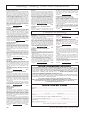
The SIRC command sequence is usually transmitted at least three times and, for
some reason best known to Sony, the data
is sent in reverse order. There is no equivalent to the control toggle bit as used in the
RC5 protocol. Like the RC5 transmission
there is no additional information transmitted to allow for error detection.
The SIRC data consists of either pulses
of 0·6ms or 1·2ms duration, meaning logic
0 and logic 1 respectively. Each pulse is
preceded by a 0·6ms pause. The pulse
length is measured by the falling edge of
the waveform generating an interrupt. The
timer value is incremented every 16
microseconds and is read on every
interrupt.
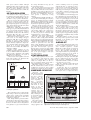
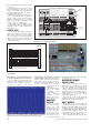
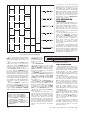
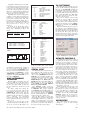
To work out the likely timer values,
divide the expected pulse width by the
timer “tick’’, illustrated in Fig.9 and
Fig.11.
pulse width = start pulse = 2·4ms = 150
timer
16ms
16ms
Fig.9. SIRC timer formula.
2·4ms
=
2·4ms + 0·6ms =
1·2ms + 0·6ms =
0·6ms + 0·6ms =
150 (start)
187 (start)
112 (logic 1)
75 (logic 0)
Fig.10. SIRC TIMERVAL for all pulse
widths.
Table 3. SIRC device code.
Command
1
2
4
6
12
16
17
18
Device
TV receiver
video tape recorder 1
video tape recorder 2
laser disk
surround sound unit
cassette deck/tuner
CD player
equaliser
Table 4. SIRC VCR FUNCTIONS
Command
0-9
9
20
21
22
24
25
26
27
28
29
Function
numerals 0 to 9
10/0
x2 play
power
eject
stop
pause
play
rewind
fast forward
record
SIRC ASSEMBLER
PROGRAM
With the SIRC code running press the
Increase Volume key on the Sony remote
control and one l.e.d. (D1) will come on
the other l.e.d. (D2) will be off. Press the
Decrease Volume key and the l.e.d.s will
invert.
To change which key controls the
l.e.d., select the appropriate value for the
key function and use that value in the
LEDDISPLAY routine. Note that the
remote control may generate different
numbers for the same function so that the
Sony equipment can distinguish
between, for example, Play for the CD
player and Play for the tape recorder. See
Tables 3 to 5.
As there is no error detection or data
verification with either of the IR protocols,
errors can occur if the IR signal is not
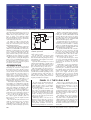
The Windows 95/98 software does not
decode the IR transmission but displays
the value of the CBINARY variable sent
from the PIC. The program also displays,
if available, a text message describing the
key pressed. This text is read from two text
files, called RC5.TXT and SIRC.TXT,
these files must be located in the same
directory as the program.
The text can easily be altered using
Notepad to coincide with the intended
remote control handset. These files store
the relevant text in ascending order. For
example, the first line is text for CBINARY = 0, the second line is for CBINARY
= 1, and so on.
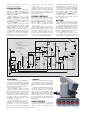
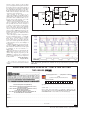
Operation of the PC software is very simple, select the serial communications port
that the PIC circuit is connected to and then
select the required protocol. The Reload key
reloads the text files if they have been
changed while the program is active. The
relevant protocol l.e.d. should flash when
data is received from the PIC circuit.
Table 5. SIRC TV FUNCTIONS
Command
0-9
9
16
17
18
19
20
21
22
23
24
25
26
27
30
31
38
39
47
Function
numerals 0 to 9
10/0
channel +
channel –
volume +
volume –
mute
power
reset
audio mode
contrast +
contrast –
colour +
colour –
brightness +
brightness –
balance left
balance right
power off
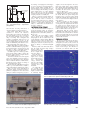
Fig.11. SIRC timing details.
The program uses the timer value to
determine the waveform. For example, if
the value is between 90 and 150 then a
logic 1 is assumed and THISBIT = 1. If
the value is between 50 and 90 then a logic
0 is assumed and THISBIT = 0. The
ADDBINARY routine is called and the
appropriate bit within CBINARY is set to
the value of THISBIT.
PC SOFTWARE
received correctly. Also, strong sunlight
falling on the sensor can generate a signal.
SERIAL PORT
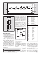
The PIC16x84 microcontroller does not
have a built-in serial port but one can be
implemented in software. Replace the
entire routine LEDDISPLAY with the
TXDATA code in the PIC assembler program. Add the two equates to the top of the
assembler program and the BCF
PORTB,RS232 to the MAIN (SIRC) or
START (RC5) procedure. This enables the
RB3 port pin to be used as an output. In
routine LOOP replace CALL LEDDISPLAY with CALL TXDATA.
The TXDATA routine works by
ANDing each data bit with the relevant bit
in CBINARY. This sets the output bit
(called RS232), then the OP (output) routine is called and takes the pin RB3 high or
low according to the value of bit RS232.
Directly changing RB3 in the TXDATA
routine would cause a timing error.
Once the RB3 output is set, this data
output value has to be held, consequently
several NOP commands are required to
ensure correct timing. There is no handshaking or data transmission from the PC,
therefore the connection from the PIC to
the serial socket has only two wires.
Everyday Practical Electronics, September 2000
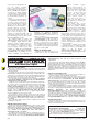
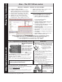
Fig.12. Example PC screen display.
REMOTE CONTROLS
A manufacturer using remote control of
its equipment can allocate any command
number to any key. Remote controls are
not required to be compatible or exchangeable with equipment from another manufacturer, hence the plethora of remote controls and protocols found in most homes.
The author has come across a remote control for a portable TV that uses RC5 coding for some of the keys and another protocol (not SIRC) for the remaining keys.
As neither PIC program decodes the
device address then the result is a wider
choice of remote controls being available.
However, if a suitable remote control handset is not available then replacement remote
controls are readily obtainable with a variety
of functions and key layout. Most of these
handsets are programmable and can replace
many different models; therefore there is an
implied choice of protocol.
Clearly the IR decoding program could
alter a variable value or the status of a
Boolean flag or control a device attached
to one of the PIC ports. A number of different functions could be added as the
assembler code associated with the LEDDISPLAY routine can be increased as
necessary. Numeric input to a PIC program via a remote control handset can
easily be achieved.
RESOURCES
The software discussed in this article is
available as stated on this month’s
Shoptalk page.
$
701