1
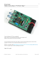
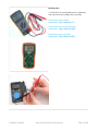
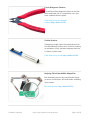
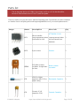
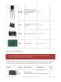
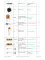
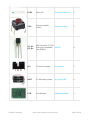
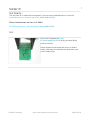
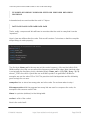
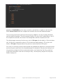
TV-B-Gone Kit
Created by lady ada
Last updated on 2015-01-24 06:45:13 AM EST
Guide Contents
Guide Contents
2
Overview
4
Make every day a "TV-free" day!"
4
See it in use!
4
Specifications
5
Credits
5
F.A.Q.
7
Make it!
9
Get ready to make your kit
9
Ready?
9
Preparation
10
Tools
10
Parts list
15
V1.1 & V1.0 Kit Parts
17
Solder it!
20
Get Ready...
20
Go!
20
Test it!
43
Test 1
43
Test 2
43
Use it!
44
Very easy!
44
Video of recommended usage
44
Design Notes
45
Design Notes
45
Power supply
45
IR LEDs
45
Button
45
Crystal
45
© Adafruit Industries
https://learn.adafruit.com/tv-b-gone-kit
Page 2 of 65
IR-Driver Transistors
46
IR-Driver-Transistors-Driver Transistor
46
Example of a single IR code
47
Code compression in v1.2
54
Download
61
Download files for the kit designs
61
Files for v1.2 PCB (and matching firmware)
61
Files for v1.1 PCB
61
Files for v1.0 PCB
62
Buy Kit
64
Forums
65
© Adafruit Industries
https://learn.adafruit.com/tv-b-gone-kit
Page 3 of 65
Overview
Make every day a "TV-free" day!"
Tired of all those LCD TVs everywhere?
Want a break from advertisements while you're trying to eat?
Want to zap screens from across the street?
The new Universal TV-B-Gone kit is what you need! This ultra-high-power version of the
popular TV-B-Gone is fun to make and even more fun to use.
Built in co-operation with Mitch Altman (the inventor of the TV-B-Gone) (http://adafru.it/c1w)
this kit is a great way to build something truly useful!
See it in use!
© Adafruit Industries
https://learn.adafruit.com/tv-b-gone-kit
Page 4 of 65
Specifications
Power: 2 AA batteries
Output: 2 narrow-beam and 2 wide-beam IR LEDs
Number of TV codes: 230 total codes, 115 for 'North America' and 115 for "Europe"
This covers pretty much every TV of the following brands, including the latest flatscreens and plasma TVs Acer, Admiral, Aiko , Allero n, Anam Natio nal, AOC,
Apex, Baur, Bell&Ho well, Brillian, Bush, Candle, Citizen, Co ntec, Co ny,
Cro wn, Curtis Mathes, Daiwo o , Dimensia, Electro graph, Electro ho me,
Emerso n, Fisher, Fujitsu, Funai, Gateway, GE, Go ldstar, Grundig,
Grunpy, Hisense, Hitachi, Infinity, JBL, JC Penney, JVC, LG, Lo gik, Lo ewe,
LXI, Majestic, Magnavo x, Marantz, Maxent, Memo rex, Mitsubishi, MGA,
Mo ntgo mery Ward, Mo to ro la, MTC, NEC, Neckermann, NetTV, Nikko ,
NTC, Otto Versand, Palladium, Panaso nic, Philco , Philips, Pio neer,
Po rtland, Pro scan, Pro to n, Pulsar, Pye, Quasar, Quelle, Radio Shack,
Realistic, RCA, Samsung, Sampo , Sansui, Sanyo , Sco tt, Sears, SEI,
Sharp, Signature, Simpso n, Sinudyne, So no lo r, So ny, So undesign,
Sylviana, Tatung, Teknika, Tho mpso n, To shiba, Universum, Viewso nic,
Wards, White Westingho use, Zenith
Max distance: more than 100 ft New! v1.2 of the kit is twice as powerful, 150 feet or
more!
Satisfaction: guaranteed!
Credits
This kit was a successful collaboration with Cornfield Electronics (http://adafru.it/c5n)!
© Adafruit Industries
https://learn.adafruit.com/tv-b-gone-kit
Page 5 of 65
© Adafruit Industries
https://learn.adafruit.com/tv-b-gone-kit
Page 6 of 65
F.A.Q.
What is a TV-B-Gone Kit?
TV-B-Gone (http://adafru.it/c1w) is a 'universal' remote control device, it is basically like a
remote control but with only the "Power" button. This is a kit version of that product.
How are the kit and original TV-B-Gone product related?
Mitch Altman (http://adafru.it/c5o) (inventor of the TV-B-Gone) and his company Cornfield
Electronics (http://adafru.it/c5n) worked together with me (Adafruit Industries) to develop
a kit version of the TV-B-Gone. Mitch thinks open source kits are awesome!
Why should I get a kit if I can just buy a TV-B-Gone ready made?
This kit is for learning how to solder and maybe even a little of how remote controls are
designed. The kit version also has 2 AA batteries and 4 high power output IR LEDs to
allow for much longer distances than the keychain product, more than 150 ft! It's also
easier to hack and adapt for other projects. However, the kit has fewer codes (so there
may find a TV once in a while that doesn't respond), is larger and heavier and requires
you to put it together.
We suggest you get one of each!
Does this kit work on all TVs?
The latest revision of the kit (v1.2) has 230 of the most common codes for TV's!
Wecouldn't include every code, but field testing has shown that nearly every TV we
encountered would turn off, even the most recent LCD and Plasma flat screen TVs!
Note that this kit will not work with LED signs, computer monitors (that are not also
televisions) and display signs that don't have a remote-control port.
Does this kit work with European TVs?
IF you have v1.1 or v1.0 kit (older) it is designed for "North American/Asia" only. A large
number of newer European TVs will work with TV-B-Gone kit, but its not as likely. For
example, instead of 90% success, its more like 50%
The v1.2 kit can be configured for either N.A. and EU zone which avoids this problem!
How close do I have to be for the TV-B-Gone kit to work?
The closer the better, but we've found that if you have pretty good aim, you can be 100'
(30m) or farther.
I'm not able to turn off the TV from more than 30 feet away, what's wrong?
First, perform the test to make sure all 4 IR LEDs are firing.
(http://adafru.it/c5p)Second, make sure you have fresh Alkaline batteries installed
Third, try to aim as best as you can at the IR receiver, usually a small dark plastic plate on
the front of the TV
Finally, try many different TVs. Some TVs simply do not respond as well from far away as
© Adafruit Industries
https://learn.adafruit.com/tv-b-gone-kit
Page 7 of 65
others.
The LEDs blink as soon as I put in batteries, is this normal?
Yes! The kit will turn on when you insert batteries or if you press the button.
When I press the button, the LEDs stop blinking, is this normal?
Yes, the button is used to reset the kit, so if its pressed, the kit is off. When you release
it, it turns on and blasts the TV-b-gone codes!
How do I get the TV-B-Gone to turn off?
The TV-B-Gone turns itself off once it is done with all the codes. This takes about 2
minutes! If you press the button, it will just start over so don't do that if you want it to
stop. There is no off switch button, just put the kit in your pocket and it will turn itself off
when it is don.
The LEDs blink for 2 seconds or less, then turn off, whats wrong?
You need to replace your batteries. Get FRESH Alkaline batteries, don't use old batteries
from the back of your desk!
I want more range! How can I make the kit more powerful?
Make sure you have fresh Alkaline batteries. They work better than rechargables
You can swap out the 2 AA battery holder for a 3 AA battery holder. This will give even
better performance! Using C or D cell batteries will give longer run time but won't
increase the power.
Do no t use 9V batteries or more than 3 1.5V alkaline batteries, you can permanently
damage the kit!
Coin cells do not work at all, don't bother using them.
How can I reprogram the TV-B-Gone kit?
Because of the limited number of pins and other elements of the kit, programming the kit
requires a little modification. For the latest version, removing R1 1.0k resistor (or cutting
one side) will allow it to be programmed.
For earlier kits, unfortunately, all four 47 ohm resistors must be removed (or one side
cut).
© Adafruit Industries
https://learn.adafruit.com/tv-b-gone-kit
Page 8 of 65
Make it!
Get ready to make your kit
Ready?
This is a vey easy kit to make, just go through each of these steps to build the kit:
1.
2.
3.
4.
Tools and preparation (http://adafru.it/c5q)
Check the parts list (http://adafru.it/c5r)
Assemble the kit (http://adafru.it/c5s)
Test the assembled kit! (http://adafru.it/c5p)
© Adafruit Industries
https://learn.adafruit.com/tv-b-gone-kit
Page 9 of 65
Preparation
Learn how to solder with tons of tutorials! (http://adafru.it/aTk)
Don't forget to learn how to use your multimeter too! (http://adafru.it/aZZ)
Tools
There are a few tools that are required for assembly. None of these tools are included. If
you don't have them, now would be a good time to borrow or purchase them. They are very
very handy whenever assembling/fixing/modifying electronic devices! I provide links to buy
them, but of course, you should get them whereever is most convenient/inexpensive. Many
of these parts are available in a place like Radio Shack or other (higher quality) DIY
electronics stores.
So ldering iro n
Any entry level 'all-in-one' soldering iron that
you might find at your local hardware store
should work. As with most things in life, you get
what you pay for.
Upgrading to a higher end soldering iron setup,
like the Hakko FX-888 that we stock in our
store (http://adafru.it/180), will make soldering
fun and easy.
Do not use a "ColdHeat" soldering iron! They
are not suitable for delicate electronics work
and can damage the kit (see
here (http://adafru.it/aOo)).
Click here to buy our entry level adjustable
30W 110V soldering iron (http://adafru.it/180).
Click here to upgrade to a Genuine Hakko FX888 adjustable temperature soldering
iron. (http://adafru.it/303)
© Adafruit Industries
https://learn.adafruit.com/tv-b-gone-kit
Page 10 of 65
So lder
You will want rosin core, 60/40 solder. Good
solder is a good thing. Bad solder leads to
bridging and cold solder joints which can be
tough to find.
Click here to buy a spool of leaded solder
(recommended for
beginners) (http://adafru.it/145).
Click here to buy a spool of lead-free
solder (http://adafru.it/734).
© Adafruit Industries
https://learn.adafruit.com/tv-b-gone-kit
Page 11 of 65
Multimeter
You will need a good quality basic multimeter
that can measure voltage and continuity.
Click here to buy a basic
multimeter. (http://adafru.it/71)
Click here to buy a top of the line
multimeter. (http://adafru.it/308)
Click here to buy a pocket
multimeter. (http://adafru.it/850)
© Adafruit Industries
https://learn.adafruit.com/tv-b-gone-kit
Page 12 of 65
Flush Diago nal Cutters
You will need flush diagonal cutters to trim the
wires and leads off of components once you
have soldered them in place.
Click here to buy our favorite
cutters (http://adafru.it/152).
So lder Sucker
Strangely enough, that's the technical term for
this desoldering vacuum tool. Useful in cleaning
up mistakes, every electrical engineer has one
of these on their desk.
Click here to buy a one (http://adafru.it/148).
Helping Third Hand With Magnifier
Not absolutely necessary but will make things
go much much faster, and it will make soldering
much easier.
Pick one up here (http://adafru.it/291).
© Adafruit Industries
https://learn.adafruit.com/tv-b-gone-kit
Page 13 of 65
© Adafruit Industries
https://learn.adafruit.com/tv-b-gone-kit
Page 14 of 65
Parts list
This is the parts list for v1.2 ONLY! If you have a v1.0 or v1.1 kit this list will be
incorrect! See below for the v1.0/v1.1 parts list guide.
Check to make sure your kit comes with the following parts. Sometimes we make mistakes
so double check everything and email [email protected] if you need replacements!
Image
Name
Descriptio n
Mo re info
Qty
ATTINY85V-10-PU
IC1
© Adafruit Industries
Microcontroller
(preprogrammed when (unprogrammed when
purchased in a kit)
not purchased from
Adafruit)
1
IC1'
8-pin socket
Generic
1
XTL1
8.00 MHz ceramic
oscillator. It might also
be blue.
8mhz ceramic
resonator
1
C2
220uF or higher
capacitor with 6.3V or
higher rating
Electrolytic Capacitor
1
C1
Ceramic 0.1uF
capacitor (104)
Ceramic Capacitor
1
https://learn.adafruit.com/tv-b-gone-kit
Page 15 of 65
1/4W 5% 10K resistor
For EU configuration
use!
R3
Generic Resistor
1
R1, R5
1.0Kohm 1/4W 5%
resistor (brown black
red gold)
Generic Resistor
2
LED2,
LED3
Narrow beam IR LED.
These have a blue-ish
tint.
Everlight IR333-A
2
LED1,
LED4
Wide beam IR LED
Everlight
IR333C/H0/L10
2
LED5
3mm LED
3mm green diffused
1
SW1
6mm tact switch
button
6mm tact switch
1
PN2907
1
Brown, Black, Orange,
Gold
PNP transistor, EBC
pinout
Q5
© Adafruit Industries
Such as PN2907 or
2N3806
https://learn.adafruit.com/tv-b-gone-kit
Page 16 of 65
Q1 Q2
Q3 Q4
NPN Transistor (TO-92)
that is pin compatible
PN2222
with 2N3904 EBC
pinout
4
ICSP
6 pin header, 0.1"x0.1"
2x3 header
spacing
1
BATT
2 x AA battery holder
Keystone 2463
1
PCB
Circuit board
Adafruit Industries
1
V1.1 & V1.0 Kit Parts
This is the parts list for v1.0 and v1.1 ONLY! If you have a v1.2 kit this list will be
incorrect, see above for the correct parts list!
Check to make sure your kit comes with the following parts. Sometimes we make mistakes
so double check everything and email [email protected] if you need replacements!
Image
Name
Descriptio n
Distributo r
Qty
ATTINY85V-10-PU
IC1
© Adafruit Industries
Microcontroller
(preprogrammed when (unprogrammed when
https://learn.adafruit.com/tv-b-gone-kit
1
Page 17 of 65
© Adafruit Industries
purchased in a kit)
not purchased from
Adafruit)
IC1'
8-pin socket
Generic
1
XTL1
8.00 MHz ceramic
oscillator. It might also
be blue.
8mhz ceramic
resonator
1
C2
100uF or higher
capacitor with 6.3V or
higher rating
Electrolytic Capacitor
1
C1
Ceramic 0.1uF
capacitor (104)
Ceramic Capacitor
1
R1-R4
47 ohm 1/4W 5%
resistor (yellow violet
black gold)
Generic Resistor
4
R5
1.0Kohm 1/4W 5%
resistor (brown black
red gold)
Generic Resistor
1
LED2,
LED3
Narrow beam IR LED.
These have a blue-ish
tint.
Everlight IR333-A
2
LED1,
LED4
Wide beam IR LED
Everlight
IR333C/H0/L10
2
https://learn.adafruit.com/tv-b-gone-kit
Page 18 of 65
© Adafruit Industries
LED5
3mm LED
3mm green diffused
1
SW1
6mm tact switch
button
6mm tact switch
1
Q1 Q2
Q3 Q4
NPN Transistor (TO-92)
that is pin compatible
PN2222
with 2N3904
4
JP2
10 pin box header
2x5 header
1
BATT
2 x AA battery holder
Keystone 2463
1
PCB
Circuit board
Adafruit Industries
1
https://learn.adafruit.com/tv-b-gone-kit
Page 19 of 65
Solder it!
Get Ready...
The first step is to solder the kit together. If you've never soldered before, check the
Preparation page for tutorials and more (http://adafru.it/c5q).
These instructio ns are fo r v1.2 ONLY
For older instructions, check this page! (http://adafru.it/c5t)
Go!
Check the kit against the parts
list (http://adafru.it/c5r) to verify you have all the
parts necessary.
Put the printed circuit board into a vise or board
holder, heat up your soldering iron and make sure
you're ready to go!
© Adafruit Industries
https://learn.adafruit.com/tv-b-gone-kit
Page 20 of 65
The first part we're going to assemble is the button.
The button is a symmetric part so it can go in two
ways. Line up the metal legs with the holes in the
circuit board and snap it in. The button should sit flat
against the circuit board.
Using your soldering iron, heat up a leg of the button
and the poke solder into it to make a nice solder
joint.
© Adafruit Industries
https://learn.adafruit.com/tv-b-gone-kit
Page 21 of 65
Repeat for all four legs. The solder points should be
clean and shiny. See the tutorials for soldering help if
you can't get it right (http://adafru.it/aTk).
© Adafruit Industries
https://learn.adafruit.com/tv-b-gone-kit
Page 22 of 65
Next is the 1.0 kilo ohm resistor R5. This is the
brown-black-red striped part. This resistor sets the
brightness of the little indicator LED. Resistors are
symmetric, so it can go in either way.
Bend the legs so it looks like a staple and insert it
into the R5 location as shown.
Then bend the legs out a bit so that when you turn
the PCB over the part doesn't fall out.
© Adafruit Industries
https://learn.adafruit.com/tv-b-gone-kit
Page 23 of 65
Solder each leg of the resistor.
© Adafruit Industries
https://learn.adafruit.com/tv-b-gone-kit
Page 24 of 65
Use the diagonal cutters to clip off the resistor legs
so that only the solder points remain.
© Adafruit Industries
https://learn.adafruit.com/tv-b-gone-kit
Page 25 of 65
Now it's time to place the small indicator LED LED5.
LED's are not symmetric and must be placed
correctly in order to work. You'll notice one leg of the
LED is longer than the other. This is the positive leg.
The positive leg goes into the hole with a + next to
it. In the picture shown, its the left hole.
Insert the LED into the correct location, and bend the
leads out to keep it from falling out when you turn
the PCB over.
Turn the PCB over and solder both leads of the LED.
© Adafruit Industries
https://learn.adafruit.com/tv-b-gone-kit
Page 26 of 65
Clip both leads of the LED.
The next part is the ceramic capacitor C1. Ceramic
capacitors are symmetric so it can go in either way.
© Adafruit Industries
https://learn.adafruit.com/tv-b-gone-kit
Page 27 of 65
Solder and clip the ceramic capacitor part.
© Adafruit Industries
https://learn.adafruit.com/tv-b-gone-kit
Page 28 of 65
Next, place 2 components. The ceramic oscillator
and the 8-pin socket. The oscillator has 3 pins and is
symmeteric. The oscillator is the timeclock for the
microcontroller, making sure that it is performing its
functions at the correct speed.
The socket is for protecting the chip and making it
easy to insert and remove.
The socket has a little notch in one end. That notch
should match the one in the picture silkscreened
onto the circuit board. This will help you place the
microcontroller in properly later.
You may need to solder one pin of the socket while
holding it it in with a finger (or tape) as the legs aren't
long enough to be bent while in place.
© Adafruit Industries
https://learn.adafruit.com/tv-b-gone-kit
Page 29 of 65
Solder the rest of the points then clip short the legs
of the oscillator.
Next grab the battery holder and clip the leads short,
to maybe 1.5" (4cm) long.
© Adafruit Industries
https://learn.adafruit.com/tv-b-gone-kit
Page 30 of 65
Strip the ends of the wire off so that there's a short
section without insulation.
Use your soldering iron to 'tin' the wire, melting
solder into it to keep the wire from fraying.
© Adafruit Industries
https://learn.adafruit.com/tv-b-gone-kit
Page 31 of 65
Insert the wires into the PCB so that the red wire
goes to the + hole and the black wire goes to the hole.
Solder the wires, then clip them if they're too long.
© Adafruit Industries
https://learn.adafruit.com/tv-b-gone-kit
Page 32 of 65
Carefully insert the microcontroller into the socket.
Make sure that the little dot (and triangle) are at the
end with the notch in the socket. In this photo, the
dot is on the upper left.
The microcontroller is the device that stores all the
codes and turns the LEDs on and off according to a
program.
Test the kit now by putting two good AA batteries
into the holder. The green indicator light should blink
to show that the microcontroller is functioning
properly. If you don't get a blinking light check the
batteries, make sure the indicator LED is in
correctly,and that the chip is in the right way.
In older kits you would have to press the button to
get the blinking to start.
Once you've verified it's working, remove the
batteries.
THIS VIDEO IS EMBEDDED WITH THE
PICTURE: http: //blip.tv/file/get/LadyadatvBGo neKitTest1692.flv (http: //adafru.it/c5u)
© Adafruit Industries
https://learn.adafruit.com/tv-b-gone-kit
Page 33 of 65
Next place the 1.0K ohm resistors, R1. This is the
base resistor for the PNP transistor.
Solder and clip the resistor.
© Adafruit Industries
https://learn.adafruit.com/tv-b-gone-kit
Page 34 of 65
Next is the 220uF electrolytic capacitor. It is polarized
so make sure it goes in the right way. The long lead
is positive, and goes into the hole marked with a +,
on the right in this photo.
Bend the capacitor so it lies down this will make it
stick out less.
© Adafruit Industries
https://learn.adafruit.com/tv-b-gone-kit
Page 35 of 65
Now place the single 2N2907 PNP transitor Q5.
© Adafruit Industries
https://learn.adafruit.com/tv-b-gone-kit
Page 36 of 65
Next are the four NPN (2N2222) transistors Q1 Q2
Q3 and Q4. These are the devices that turn on and
off the high power IR LEDs. The microcontroller
doesn't have the capability to provide a lot of power
directly to the LEDs so these transistors assist it.
Transistors have three pins. Bend the middle pin
back a little and insert it so that the rounded and
flattened sides match up with the picture
silkscreened onto the circuit board, as shown. The
transistor won't be able to sit flat against the circuit
board, so just make it poke up a few millimeters.
Insert all 4 transistors.
Turn the PCB over and solder in all the transistors.
Then clip the wires.
© Adafruit Industries
https://learn.adafruit.com/tv-b-gone-kit
Page 37 of 65
Next is the IR LEDs. Start with LED1, a clear IR led.
Like the small indicator LED, it has polarity. Make sure
the longer, positive lead is on the right, as shown.
Bend the LED over 90 degrees so it sticks out over
the edge of the circuit board, see below
© Adafruit Industries
https://learn.adafruit.com/tv-b-gone-kit
Page 38 of 65
Bend the LED over 90 degrees so it sticks out over
the edge of the circuit board.
Flip over the PCB and solder it to the bottom.
© Adafruit Industries
https://learn.adafruit.com/tv-b-gone-kit
Page 39 of 65
Now solder it to the top of the circuit board.
Then clip the leads.
© Adafruit Industries
https://learn.adafruit.com/tv-b-gone-kit
Page 40 of 65
You're done soldering! Now you may want to
perform some tests to make sure it's working. Visit
the Testing page for more info. (http://adafru.it/c5p)
If you're in the EU, UK, Australia, place the remaining
10K resistor into R3. This will tell the micrcontroller
to use the EU database.
If you're in Asia or North America do not place R3.
If you're planning to reprogram the chip, solder in the
6-pin ICSP header. The long pins go up.
© Adafruit Industries
https://learn.adafruit.com/tv-b-gone-kit
Page 41 of 65
Place the doublesided foam sticky on the circuit
board. Remove the other side and press the battery
holder on.
Congrats, you're done!
© Adafruit Industries
https://learn.adafruit.com/tv-b-gone-kit
Page 42 of 65
Test it!
Test 1
With batteries in, make sure that the green LED blinks after you press the power button.
Test 2
Digital cameras can detect infra-red light but our eyes can't. Use a digital camera, webcam
or camcorder and look through the digital viewfinder at the IR LEDs, after pressing the
button, the LEDs should flash.
© Adafruit Industries
https://learn.adafruit.com/tv-b-gone-kit
Page 43 of 65
Use it!
Very easy!
1. Simply point the device as best you can so that the Infrared LEDs are aimed at the
television you'd like to turn off.
2. Press the button once. Don't hold the button down! It will just keep resetting itself. The
codes start to transmit once you release the button.
3. The indicator LED will blink for every code it sends. Keep the TV-B-Gone pointed at
your target until it turns off. The 4 infrared LEDs will not blink visibly because human
eyes can't see infrared light.
4. When the TV-B-Gone is finished, the indicator light will blink quickly a few times and
then stop.
If you press and release the button while it's sending out codes, it will reset and start over
from the beginning.
The most popular codes are at the beginning, less common codes are at the end of the list.
Video of recommended usage
© Adafruit Industries
https://learn.adafruit.com/tv-b-gone-kit
Page 44 of 65
Design Notes
Design Notes
Here are some notes on how the TV-B-Gone kit is designed!
Be sure to read the accompanying firmware for details on how the PWM and timers are
initialized!
Power supply
The kit is powered by 2 AA batteries. It's important that the power supply voltage be
between 2.5V and 5V. Higher than that can damage the kit. Lower is too low for it to work. It's
also important that the power supply be able to supply 400-1000mA easily. For AA's this is
not a problem. AAA's may have issues. C or D cells are fine as are many Lithium Ion/Polymer
batteries. Check your batteries if you're not using standard Alkaline AA's.
Better batteries will get you more range. "Lithium" 1.5V are excellent, Alkalines are good,
and then recharagables are OK but not fantastic. Coin cells will not work at all. 9V batteries
will kill the device. See this tutorial on batteries for ideas (http://adafru.it/c5x).
Using 3 batteries will also greatly improve range. 4 gets a little dangerous because 4
Alkalines is 6V which is above the suggested voltage for the chip and may damage it. 4
NiMH cells is a safe voltage for the chip, but tends to burn out the LEDs.
Stick to 2 o r 3 batteries!
IR LEDs
The 4 blaster LEDs are IR LEDs. They are 940nm wavelength emitters which is the most
common IR used for remotes. The blue ones are narrow output (longer range but narrower),
the clear ones are wide output (shorter range but wider throw). Together they should let you
to hit most TVs!
Button
There is one button. Pressing & releasing will start the kit to emit IR codes. The button is
actually hooked up to the microcontroller's reset pin and tells the chip to reset. When the
chip resets it automatically emits all the codes in its library. When it's done it goes into a
very-low-power sleep mode and awaits another button press.
Crystal
© Adafruit Industries
https://learn.adafruit.com/tv-b-gone-kit
Page 45 of 65
The 8.0 MHz resonator isn't technically a crystal but it acts the same. It generates the
8.0MHz timing clock to keep the chip on time and generating precise waveforms. There is an
internal 8mhz resonator on the chip but it's not nearly precise enough and varies with battery
voltage and temperature. Using an external resonator prevents that. The resonator MUST be
8.0MHz as the code is specifially written for that value. If you decide to change the crystal
speed (there's no reason to but people ask) you will have to change the code for the new
value by updating the Makefile and completely recompiling.
IR-Driver Transistors
The IR LEDs have more than 100mA going through them. This is way more than a
microcontroller pin can supply (usually 20 to 40 mA max!) so we use a 'driving' transistor.
These NPN transistors amplify the power of a microcontroller pin and are designed to turn
off currents of over 100mA. When the base pin is pulled high (though the base resistor) the
transistor turns on and the LED turns on too. When the base pin is pulled to ground, the
transistor turns off and no current passes through the LED.
In v1.0 kits 1 pin on the microcontroller controls four transistors each.
In v1.1 kits two pins on the microcontroller each control two transistors each (4 total) - this
increased the base current to give better range.
(Please note that at the DC currents we are pushing through the transistor and the LED, the
beta of the transistor is not 200 but closer to maybe 20-50, Vbe is about a volt, and Vce_sat
grows to a volt or so. Of course it depends on the transistor but just be aware that 'simple'
transistor modeling is not valid anymore.)
IR-Driver-Transistors-Driver Transistor
In v1.2 we decided that we really wanted an extra pin to do region detection. We could go
back to having one micro pin control all four transistors but the range would suffer so instead
we have a PNP transistor that will buffer the weak microcontroller pin and push plenty of
current into the bases of the IR driver transistors.
© Adafruit Industries
https://learn.adafruit.com/tv-b-gone-kit
Page 46 of 65
Now we use one pin, PB0 to drive Q5 the PNP which connects the bases of the driver NPNs
with a path to VCC.
(Note we do not use base resistors because the power supply droop, the NPN's Vce_sat
and the IR LED voltage drop will max out and limit the base current and then the Vce of the
PNP will sit at the 'right' voltage.)
R2 was placed in case we needed 'help' with getting charge off of the base. Its not needed
so ignore it.
Example of a single IR code
For this example we will use the Sony power on/off IR code. It's the first code in the North
American database and the 4th in the EU database. It's very simple and commonly
documented!
© Adafruit Industries
https://learn.adafruit.com/tv-b-gone-kit
Page 47 of 65
Let's pretend we have a Sony remote, we want to extract the code from it. We'll hookup a IR
sensor (like a basic photocell!) and listen in, what we see is the following:
Basically we see pulses or IR signal. the yellow 'blocks' are when the IR LED is transmitting
and when there is only a line, the IR LED is off. (Note that the voltage being at 3VDC is just
because of the way I hooked up the sensor, if I had swapped the pullup for a pulldown it
would be at ground.)
The first 'block' is about 2.5ms long (see the cursors and the measurement on the side)
If you zoom into one of those blocks...
© Adafruit Industries
https://learn.adafruit.com/tv-b-gone-kit
Page 48 of 65
You see that they're not really 'blocks' but actually very fast pulses!
If you zoom in all the way...
© Adafruit Industries
https://learn.adafruit.com/tv-b-gone-kit
Page 49 of 65
You can measure the frequency of the IR pulses. As you can tell by the cursors and the
measurements on the side, the frequency is about 37.04KHz
OK so now we can understand how IR codes are sent. The IR transmitter LED is quickly
pulsed (PWM - pulse width modulated) at a high frequency of 38KHz and then that PWM is
likewise pulsed on and off much slower, at times that are about 1-3 ms long.
Why not have the LED just on and off? Why have PWM 'carrier' pulsing? Many reasons!
One reason is that this lets the LED cool off. IR LEDs can take up to 1 Amp (1000 milliamps!)
of current. Most LEDs only take 20mA or so. This means IR LEDs are designed for highpower blasting BUT they can only take it for a few microseconds. By PWM'ing it, you let the
LED cool off half the time.
Another reason is that the TV will only listen to certain frequencies of PWM. So a Sony
remote at 37KHz won't be able to work with a JVC DVD player that only wants say 50KHz.
Finally, the most important reason is that by pulsing a carrier wave, you reduce the affects of
ambient lighting. The TV only looks for changes in light levels that clock in around 37KHz. Just
like it's easier for us to tell differences between audio tones than to pin down the precsise
© Adafruit Industries
https://learn.adafruit.com/tv-b-gone-kit
Page 50 of 65
pitch of a tone (well, for most people at least)
OK so now we know the carrier frequency. Its 37KHz. Next lets find the pulse widths!
Looking back at the first scope picture:
The first pulse is 2.5ms. We can use the cursors to measure the remaining pulses. I'll spare
you the 12 images and let you know that the pulses are:
PWM ON
OFF
2.4 ms
0.6 ms
1.2 ms
0.6 ms
0.6 ms
0.6 ms
1.2 ms
0.6 ms
© Adafruit Industries
https://learn.adafruit.com/tv-b-gone-kit
Page 51 of 65
0.6 ms
0.6 ms
1.2 ms
0.6 ms
0.6 ms
0.6 ms
0.6 ms
0.6 ms
1.2 ms
0.6 ms
0.6 ms
0.6 ms
0.6 ms
0.6 ms
0.6 ms
0.6 ms
0.6 ms
270 ms
In reality the code is emitted twice:
PWM ON
OFF
2.4 ms
0.6 ms
1.2 ms
0.6 ms
0.6 ms
0.6 ms
1.2 ms
0.6 ms
0.6 ms
0.6 ms
1.2 ms
0.6 ms
0.6 ms
0.6 ms
0.6 ms
0.6 ms
1.2 ms
0.6 ms
0.6 ms
0.6 ms
0.6 ms
0.6 ms
© Adafruit Industries
https://learn.adafruit.com/tv-b-gone-kit
Page 52 of 65
0.6 ms
0.6 ms
0.6 ms
270 ms
2.4 ms
0.6 ms
1.2 ms
0.6 ms
0.6 ms
0.6 ms
1.2 ms
0.6 ms
0.6 ms
0.6 ms
1.2 ms
0.6 ms
0.6 ms
0.6 ms
0.6 ms
0.6 ms
1.2 ms
0.6 ms
0.6 ms
0.6 ms
0.6 ms
0.6 ms
0.6 ms
0.6 ms
0.6 ms
-
In previous versions (v1.0 and v1.1) we didn't do any compression. Instead we made the
code literally spit out each pulse:
// Code 000 -- Sony, Baur, Neckermann, Otto Versand, Palladium, Quelle, SEI, Sinudyne, Sonolor, Universu
const struct powercode sonyCode PROGMEM = {
freq_to_timerval(38400), // 38.4 KHz
{{240, 60},
{120, 60},
{60 , 60},
{120, 60},
{60 , 60},
{120, 60},
{60 , 60},
{60 , 60},
{120, 60},
© Adafruit Industries
https://learn.adafruit.com/tv-b-gone-kit
Page 53 of 65
{60 , 60},
{60 , 60},
{60 , 60},
{60 , 2700},
{240, 60},
{120, 60},
{60 , 60},
{120, 60},
{60 , 60},
{120, 60},
{60 , 60},
{60 , 60},
{120, 60},
{60 , 60},
{60 , 60},
{60 , 60},
{60 , 0}// end of code
}
};
You can see that the first entry is a little function that converts the 38.4 KHz (38400 since we
can't use floating point here) into a 'timer value' We use the built-in 8-bit PWM module in the
chip, so we can set the frequency with an 8 bit value. Note that that value is not actually the
frequency but is calculated thusly: timer_val = ((F_CPU / freq - 1)/ 2) where F_CPU is
the clock crystal. We use an 8 MHz crystal so to generate 3.84 KHz for example, we use the
value 103 or 104. The precision isn't that important and it's definately good enough for our
uses.
Then comes a long list of all the codes (I cleaned it up a little to match the 'ideal' code
readings).
The timer value takes up 1 byte. Each number in the code table is 16 bits long so it can hold
numbers larger than 255. That means each code pair line takes up 4 bytes. So the total
memory storage needed is 1 + 26 * 4 = 105 bytes
Code compression in v1.2
While the above is more readable, it's very 'bulky' and hard to fit more than 40 codes. That
sucks! We want MORE codes. So we will compress them. (This code is similar to the Damian
Good/Caitsith compression scheme but not identical. However we are indebted to him for
the great work!) Remember that the code looked like this:
PWM ON
OFF
2.4 ms
0.6 ms
© Adafruit Industries
https://learn.adafruit.com/tv-b-gone-kit
Page 54 of 65
1.2 ms
0.6 ms
0.6 ms
0.6 ms
1.2 ms
0.6 ms
0.6 ms
0.6 ms
1.2 ms
0.6 ms
0.6 ms
0.6 ms
0.6 ms
0.6 ms
1.2 ms
0.6 ms
0.6 ms
0.6 ms
0.6 ms
0.6 ms
0.6 ms
0.6 ms
0.6 ms
270 ms
Since you can see that the pairs of on/off codes repeat (not coincedentally!) we can
squeeze the code down by creating a table of the "unique" pairs. I've ordered them so the
first column is sorted first and then by the second column:
INDEX #
PWM ON
OFF
0
0.6 ms
0.6 ms
1
0.6 ms
270 ms
2
1.2 ms
0.6 ms
3
2.4 ms
0.6 ms
Then our code would look like this:
CODE PAIR INDEX
© Adafruit Industries
https://learn.adafruit.com/tv-b-gone-kit
Page 55 of 65
#3
#2
#0
#2
#0
#2
#0
#0
#2
#0
#0
#0
#1
Where to decode, we look up the on/off code pair in the Timing Table!
We can store the timing table in memory thusly:
const uint16_t code_na000Times[] PROGMEM = {
60, 60,
60, 2700,
120, 60,
240, 60,
};
The co nst keyword indicates that these are 'constants' - not variable data.
The uint16_t keyword indicates that the data is 16-bits long. We need 16 bits because
some of the lengths are longer than 255 (which is the max size one can store in 8-bit data).
© Adafruit Industries
https://learn.adafruit.com/tv-b-gone-kit
Page 56 of 65
Then comes the name, this is the co de_na000Times timing table, which goes with code
na000 (sony)
Next is [] which indicates it's an array of values.
The PROGMEM tells the compiler to store it in ROM. This is important because there is only
512 bytes of RAM but 8192 bytes of ROM (flash). By default the compiler thinks we want to
store stuff in RAM because we can then change it easily. ROM cannot be modified by the
chip itself easily.
Finally, we have the table. We can't use 'floating points' so instead of storing "0.6 ms" we
store "60" (multiplying everything by 100) This gives us the precision we want. When it's
time to actually use the numbers we just take into account that they're 100 times too large.
This code table takes 8 (entries) * 2 (bytes each) = 16 bytes
Now we must store the code itself, seperately. (We don't stick the two together because
multiple codes use the same timing tables so we save memory by keeping them seperate.)
Let's convert the code index list into binary. Because we only have 4 different codes, we
only need 2 bits to describe each code pair. If we had 5 different codes, we'd need 3 bits
which can store up to 8 different values. Once we hit 9 different code pairs, we need 4 bits,
etc...
Now one thing we skipped before is that the code is actually transmitted twice so we need
to double up the table!
CODE PAIR INDEX
In Binary
#3
11
#2
10
#0
00
#2
10
#0
00
#2
10
#0
00
#0
00
#2
10
#0
00
© Adafruit Industries
https://learn.adafruit.com/tv-b-gone-kit
Page 57 of 65
#0
00
#0
00
#1
01
#3
11
#2
10
#0
00
#2
10
#0
00
#2
10
#0
00
#0
00
#2
10
#0
00
#0
00
#0
00
#1
01
Great! We have our full code now. So our code can now be turned into a chunk of data, we
append each code pair index to each other to create this 'string' of bits:
1110001000100000100000000111100010001000001000000001
Which we divide into 8 bit groups:
11100010 00100000 10000000 01111000 10001000 00100000
0001
© Adafruit Industries
https://learn.adafruit.com/tv-b-gone-kit
Page 58 of 65
Then we 'pad' out the final chunk so it's a full 8 bits long:
11100010 00100000 10000000 01111000 10001000 00100000
00010000
In hexadecimal, we can describe the code in 7 bytes:
0xE2 0x20 0x80 0x78 0x88 0x20 0x10
That's -really- compressed. We will have to now describe the code in a way that it can be
'unpacked'
Here is how we will describe the code. First we will create a C structure so that the compiler
will put things in order properly:
// The structure of compressed code entries
struct IrCode {
uint8_t timer_val;
uint8_t numpairs;
uint8_t bitcompression;
uint16_t const *times;
uint8_t codes[];
};
The first byte timer_val is the way we set the carrier frequency. We use the built-in 8-bit
PWM module in the chip, so we can set the frequency with an 8 bit value. Note that that value
is not actually the frequency but is calculated thusly: timer_val = ((F_CPU / freq - 1)/ 2)
where F_CPU is the clock crystal. We use an 8 MHz crystal so to generate 3.84 KHz for
example, we use the value 103 or 104. The precision isn't that important and it's definately
good enough for our uses.
numpairs lets us store how many pairs are in the code. So we know when to stop!
bitco mpressio n tells the program how many bits we used to compress the code, for
example in this case we used 2 bits
times is a pointer (address) to the timing table
co des is a list of the codes!
Next is the code itself:
© Adafruit Industries
https://learn.adafruit.com/tv-b-gone-kit
Page 59 of 65
const struct IrCode code_na000Code PROGMEM = {
freq_to_timerval(38400),
26,
// # of pairs
2,
// # of bits per index
code_na000Times,
{
0xE2,
0x20,
0x80,
0x78,
0x88,
0x20,
0x10,
}
};
co nst and PROGMEM are the same as before, just tells the compiler to stick this into
ROM. struct IrCo de tells the compiler this must be in the form we indicated earlier.
Then we have the function that turns the frequency (38400 is our way of writing 38.4 KHz)
into the right 8 bit number. Then the number of pairs (13 in the code, emitted twice!), the 2bit compression method, the name of the timing table, and the compressed code.
The final storage necessary for the sony code is 16 bytes (for the table) + 1 (for the timer
val) + 1 (for the compression notice) + 2 (for the timer table pointer) + 7 (for the code
itself) = 27 bytes Compare that to the previous version that took 105 bytes!
Of course, to do this by hand is awful. Instead, we grabbed the data from a 'univeral remote'
and used a perl script (check the download page) to automate it. Because the timing is not
very precise coming out of these universal remotes, we 'cleaned up' the Sony code but
you'll notice that other codes are not nearly as tidy - the frequency may be off, the pulse
widths varying, etc.
© Adafruit Industries
https://learn.adafruit.com/tv-b-gone-kit
Page 60 of 65
Download
Download files for the kit designs
Files for v1.2 PCB (and matching firmware)
Here are the hardware and firmware files for v1.2, distributed under Creative Commons 2.5
Attribution, Share-Alike:
Schematic and Layout files in Eagle format on github (http://adafru.it/c5y) (to download
click Download in top right)
Schematic in PNG (http://adafru.it/c5z)
Firmware (http://adafru.it/cmV) for AVR-GCC
Caitsith modded the v1.2 firmware to support 'looping' if its set to US or EU only, check it
out (http://adafru.it/cmW)
Files for v1.1 PCB
Here are the hardware and firmware files for v1.1 PCB, distributed under Creative Commons
2.5 Attribution, Share-Alike:
Schematic (http://adafru.it/cmX) and Layout (http://adafru.it/cmY) files in Eagle format
Firmware (http://adafru.it/cmZ) for AVR-GCC
Newer firmware with fix for 'always on' bug (?) (http://adafru.it/cn0)
© Adafruit Industries
https://learn.adafruit.com/tv-b-gone-kit
Page 61 of 65
Files for v1.0 PCB
Here are the hardware and firmware files for v1.0 PCB, distributed under Creative Commons
2.5 Attribution, Share-Alike:
Schematic (http://adafru.it/cne) and Layout (http://adafru.it/cnf) files in Eagle format
Firmware (http://adafru.it/cng) for AVR-GCC
© Adafruit Industries
https://learn.adafruit.com/tv-b-gone-kit
Page 62 of 65
© Adafruit Industries
https://learn.adafruit.com/tv-b-gone-kit
Page 63 of 65
Buy Kit
Buy Kit (http://adafru.it/c5J)
© Adafruit Industries
https://learn.adafruit.com/tv-b-gone-kit
Page 64 of 65
Forums
Forums (http://adafru.it/forums)
© Adafruit Industries
Last Updated: 2015-01-24 06:45:17 AM EST
Page 65 of 65