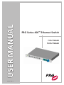
1
USER MANUAL
0 2 . 9 80 1 . 0 00 1 A
02.9801.0001 A
PRG Series 400™ Ethernet Switch
7-Port Model
10-Port Model
-1
AutoPar™, PRG Series 400™, Mbox Extreme™, Virtuoso®, Virtuoso® DX, Virtuoso® DX2, and Visionary™ 3D
are trademarks of Production Resource Group, LLC, registered in the U.S. and other countries.
Neutrik®, EtherCon®, and PowerCon® are registered trademarks of Neutrik AG.
All other brand or product names which may be mentioned in this manual are trademarks or registered trademarks of their respective companies.
This manual is for informational use only and is subject to change without notice. Please check www.prg.com for latest version.
PRG assumes no responsibility or liability for any claims resulting from errors or inaccuracies that may appear in this manual.
PRG Series 400™ Ethernet Switch User Manual
Version as of: March 28, 2007 | PRG part number: 02.9801.0001 A
Production Resource Group
Dallas Office
8617 Ambassador Row, Suite 120
Dallas, Texas 75247
www.prg.com
PRG Series 400™ Ethernet Switch User Manual
©2006-2007 Production Resource Group, LLC. All Rights Reserved.
INTRODUCTION : ABOUT THIS MANUAL
Introduction
About This Manual
This manual provides necessary information regarding product safety, installation, and operation for
the following PRG equipment:
•
PRG Series 400™ 10-Port Ethernet Switch (20.9801.0200)
•
PRG Series 400™ 7-Port Ethernet Switch (20.9801.0200.07)
Familiarizing yourself with this information will help you get the most out of your PRG product.
WARNING: It is important to read ALL accompanying safety and installation instructions to avoid
damage to the product and potential injury to yourself or others.
Additional Documentation
For more information on related equipment, refer to the following PRG manuals:
•
PRG Series 400™ Power and Data Distribution System User Manual (02.9680.0001)
•
PRG Series 400™ Power and Data Distribution System Service Manual (02.9680.0010)
•
Virtuoso® Node User Manual (02.9669.0001)
•
Virtuoso® Node Plus User Manual (02.9801.0301)
For more information regarding DMX512 systems, refer to the DMX512/1990 & AMX 192 Standards
publication available from United States Institute for Theatre Technology, Inc. (USITT).
USITT
6443 Ridings Road
Syracuse, NY 13206-1111 USA
1-800-93USITT
www.usitt.org
0 2. 9 8 0 1. 0 0 01 A
1
PRG SERIES 400™ ETHERNET SWITCH USER MANUAL
Customer Service
Our comprehensive technical services department ensures you get the full benefit of being a PRG
customer. Whether your needs are simple or complex, our full-time staff of experienced professionals
are on-hand to provide support. For assistance, contact your nearest PRG office:
PRG Dallas (International Service)
8617 Ambassador Row, Suite 120
Dallas, Texas 75247
Ph: 1.214.630.1963
Fx: 1.214.630.5867
Service Fx: 214.638.2125
Service Email: [email protected]
PRG Las Vegas
6050 S. Valley Vw Blvd.
Las Vegas, Nevada 89118
Ph: 1.702.942.4774
Fx: 1.702.942.4775
PRG Los Angeles
9111 Sunland Blvd.
Sun Valley, California 91352
Ph: 1.818.252.2600
Fx: 1.818.252.2620
PRG Nashville
8351 Eastgate Blvd.
Mount Juliet, Tennessee 37122
Ph: 1.615.834.3190
Fx: 1.615.834.3192
PRG New York
7777 West Side Avenue
North Bergen, New Jersey 07047
Ph: 1.201.758.4000
Fx: 1.201.758.4312
PRG Orlando
1902 Cypress Lake Dr.
Orlando, Florida 32837
Phone: 1.407.855.8060
Fax: 1.407.855.8059
PRG Canada
2480 Tedlo Street
Mississauga, Ontario L5A 3V3 Canada
Ph: 905.270.9050
Fx: 905.270.2590
PRG Asia
Asagami Fukagawa Logistics Center B-4F
2-2-1 Shiohama, Koto-ku, Tokyo, Japan 135-0043
Ph: 81.3.5439.4091
Fx: 81.3.5439.4092
PRG Europe
20-22 Fairway Drive
Greenford, Middlesex, UB6 8PW
Ph: +44.208.575.6666
Fx: +44.208.575.0424
For additional resources and documentation, please visit our website at: www.prg.com
2
0 2 . 98 0 1 . 00 0 1 A
OVERVIEW : 10-PORT ETHERNET SWITCH
Overview
10-Port Ethernet Switch
The PRG Series 400™ 10-Port Ethernet Switch provides a powerful and convenient interface between
Virtuoso® or DMX512 control consoles and their control equipment. The 10-Port Ethernet Switch
offers two types of connections: isolated copper Ethernet ports and fiber optic ports. The fiber optic
ports provide the ability to send fast and reliable information up to 2 kilometers away without the need
for repeaters using Virtuoso Fiber Optic Cable. The copper Ethernet connections offer the ability to
combine standard copper connections with fiber optic transmissions. Note: Copper connections are
limited to a maximum distance of 300 feet.
The 10-Port Ethernet Switch automatically determines the speed of each network connection based on
the equipment connected to the switch and supports multiple connections with transmission and
reception occurring simultaneously.
Features:
•
Seven isolated copper Ethernet ports for input of 10Base-T and 100Base-TX standard signal
(Neutrik® EtherCon® connectors).
•
Three fiber optic Ethernet ports for transmission of 100Base-FX standard signal. Two ports allow
use of the Virtuoso Fiber Optic Cable input connector and one port allows use of the Virtuoso®
Fiber Optic Cable output connector.
•
Automatic detection and configuration of input signal speed.
•
Link, Transmission, and Reception status LEDs for all ports.
•
Neutrik® PowerCon® connector for input AC supply.
•
DC power status LED.
•
Standard 1U 19" rack mount chassis.
Included Items
The following illustration shows all items included with this model:
PRG Series 400™ 10-Port
Ethernet Switch (20.9801.0200)
AC Line Cord 208V
PowerCon® Cable Assembly
(25.9801.0214)
Figure 1: 10-Port Ethernet Switch Included Items
0 2. 9 8 0 1. 0 0 01 A
3
PRG SERIES 400™ ETHERNET SWITCH USER MANUAL
Controls and Indicators
The Series 400™ 10-Port Ethernet Switch contains the following connections and LED indicators.
Fiber Optic Input ports for fiber optic
cables with input
Fiber Optic Output connectors.
port for a fiber optic
cable with an output
connector.
DC Power Indicator indicates AC power is applied.
10/100 Base T Connections input/output ports for standard signals.
Ethernet LEDs indicates valid Ethernet
link, transmit and receive
for each connection when lit.
Fiber Data LEDs indicates valid Fiber
link, transmit and receive
for each connection when lit.
Figure 2: 10-Port Ethernet Switch Front Panel
Neutrik Connector Allows connection of AC Line Cord 208V PowerCon Cable (supplied).
Figure 3: 10-Port Ethernet Switch Rear Panel
4
0 2 . 98 0 1 . 00 0 1 A
OVERVIEW : 7-PORT ETHERNET SWITCH
7-Port Ethernet Switch
The PRG Series 400™ 7-Port Ethernet Switch provides a powerful and convenient interface between
Virtuoso® or DMX512 control consoles and their control equipment. The 7-Port Ethernet Switch
provides seven isolated copper Ethernet ports. Note: Copper connections are limited to a maximum
distance of 300 feet.
The 7-Port Ethernet Switch automatically determines the speed of each network connection based on
the equipment connected to the switch and supports multiple connections with transmission and
reception occurring simultaneously.
Features:
•
Seven isolated copper Ethernet ports for input of 10Base-T and 100Base-TX standard signal
(Neutrik® EtherCon® connectors).
•
Automatic detection and configuration of input signal speed.
•
Link, Transmission, and Reception status LEDs for all ports.
•
Neutrik® PowerCon® connector for input AC supply.
•
DC power status LED.
•
Standard 1U 19" rack mount chassis.
Included Items
The following illustration shows all items included with this model:
PRG Series 400™ 7-Port
Ethernet Switch (20.9801.0200.07)
AC Line Cord 208V
PowerCon® Cable Assembly
(25.9801.0214)
Figure 4: 7-Port Ethernet Switch Included Items
0 2. 9 8 0 1. 0 0 01 A
5
PRG SERIES 400™ ETHERNET SWITCH USER MANUAL
Controls and Indicators
The Series 400™ 7-Port Ethernet Switch contains the following connections and LED indicators.
DC Power Indicator indicates AC power is applied.
10/100 Base T Connections input/output ports for standard signals.
Ethernet LEDs indicates valid Ethernet
link, transmit and receive
for each connection when lit.
Figure 5: 7-Port Ethernet Switch Front Panel
Neutrik Connector Allows connection of AC Line Cord 208V PowerCon Cable (supplied).
Figure 6: 7-Port Ethernet Switch Rear Panel
6
0 2 . 98 0 1 . 00 0 1 A
INSTALLATION : INSTALLING ETHERNET SWITCH
Installation
Installing Ethernet Switch
A Series 400™ Ethernet Switch can be used independently or installed directly in a Series 400 rack
chassis, using any blank space above the LED Meter Module.
To install in Series 400 rack:
Step
1. Install Ethernet Switch as required in top portion of rack chassis (Figure 7).
Step
2. At Ethernet Switch rear panel, connect AC Line Cord 208V PowerCon® Cable (supplied) to
Neutrik® connector.
Step
3. After power is applied, verify that ON indicator is lit.
Step
4. At front panel, connect data cables as required. Refer to “Connecting Ethernet Switch to
System” on page 8.
SERIES 400 RACK CHASSIS
3U of rack space for
adding additional signal
processing devices.
LED Meter Module
EXAMPLE CONFIGURATION
S400 Rack Components May Vary
Figure 7: Series 400 Rack
0 2. 9 8 0 1. 0 0 01 A
7
PRG SERIES 400™ ETHERNET SWITCH USER MANUAL
Connecting Ethernet Switch to System
The Series 400™ 10-Port Ethernet Switch connects Ethernet devices using both CAT5e copper wire
and armored fiber optic cable. Copper wire communication ports conform to 10/100Base-Tx standards
and the fiber ports conform to 10/100Base-Fx standards. The Series 400™ 7-Port Ethernet Switch
connects Ethernet devices using only CAT5e copper wire.
AC Input
Virtuoso Nodes
or
Any Ethernet Device
(up to 7)
Fiber Optic
Fiber Optic
10/100Base-T
10/100Base-T
10/100Base-T
10/100Base-T
10/100Base-T
10/100Base-T
10/100Base-T
SERIES 400 ETHERNET SWITCH
Fiber Optic Out to Additional Switches
Input from
a Virtuoso Console
or another switch
Input from
a Virtuoso Console
or another switch
10-Port Model Only
Figure 8: Device Connection Diagram
The following example system diagrams illustrate an Ethernet Switch being used with a Series 400
Power and Data Distribution Rack.
FIBER OPTIC CABLE
FIBER OPTIC CABLE
TO OTHER
SWITCHES
PRG S-400 10-PORT
ETHERNET SWITCH
TO OTHER
DEVICES
VIRTUOSO NODE
A
B
DMX UNIVERSE
CABLES
VIRTOUSO CONSOLE A
A
A
B
B
CAT5e CABLES
A
B
VIRTOUSO CONSOLE B
SERIES 400 RACK
* Fiber optic connections available only with the 10-Port Ethernet Switch model.
Figure 9: Sample System Connection Diagram 1
8
0 2 . 98 0 1 . 00 0 1 A
INSTALLATION : CONNECTING ETHERNET SWITCH TO SYSTEM
FIBER OPTIC CABLE
FROM REMOTE RACKS
FIBER OPTIC CABLE
TO REMOTE RACKS
PRG S-400 10-PORT
ETHERNET SWITCH
CAT5e CABLE TO
LOCAL RACKS
A
B
A
A
B
B
A
B
A
B
SERIES 400 RACK
* Fiber optic connections available only with the 10-Port Ethernet Switch model.
Figure 10: Sample System Connection Diagram 2
0 2. 9 8 0 1. 0 0 01 A
9
PRG SERIES 400™ ETHERNET SWITCH USER MANUAL
Specifications
Technical Specifications
POWER REQUIREMENT: 90 to 264 VAC, 47 to 63 Hz
Draws less than 60 watts continuously.
COOLING:
Convection.
OPERATING TEMP:
-20°C to 50°C (-4°F to 122°F)
COPPER PORTS:
Seven isolated copper ports that can accept Ethernet signals using either 10Base-T
or 100Base-TX standards. Automatic detection and configuration of input signal
speed.
FIBER OPTIC PORTS:
(10-Port model only) Three fiber optic ports that can accept 100Base-FX Ethernet
signal. The speed and direction of these ports are fixed. The ports use 62.5/125um
multi-mode fiber media at 1300nm wavelength and operate up to a 2KM distance.
INDICATORS:
Green LED power indicator to show that DC power has been applied.
Status LEDs for each port indicating Link, TX Data, and RX Data.
HOUSING:
Standard 1U 19" rack mount chassis.
WEIGHT:
4.5 lbs (2.04 kg)
COMPLIANCE:
United States: ANSI/UL 60950-1-UL Standard for Safety for Information
Technology Equipment Safety
Canada: CAN/CSA C22.2 No. 60950-1 Information Technology Equipment Safety
Europe: CE Mark
12"
(305 mm)
1.72"
(44 mm)
19"
(483 mm)
11"
(279 mm)
10-Port Model Shown
All models have the same dimensions
10
0 2 . 98 0 1 . 00 0 1 A