1
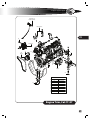
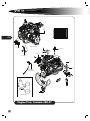
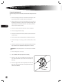
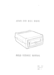
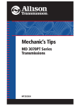
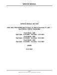
Power / Drivetrain
Overview
The Blue Bird Vision’s engine/transmission package is either a Caterpillar C7 or Cummins ISB in-line six cylinder diesel engine mated to an Allison PTS 2200, PTS 2500, or
PTS 3000 Series™ five-speed automatic transmission. Both engine and transmission
have electronic control modules. For detailed instruction on engine maintenance
and repair, please consult the appropriate Caterpillar or Cummins publication. Check
with your Blue Bird Dealer or the nearest Caterpillar or Cummins dealer to ensure you
are working with the proper publication.
Engine/Transmission Removal
1. Drain the fluids from the engine, transmission and hydraulic system into suitable containers for disposal in accordance with local, state and federal regulations.
229
2. Remove the hood.
3. Remove the front bumper.
4. Remove the breather and the breather intake pipe. Ensure the openings into
the turbo and air pipes are covered to prevent introduction of debris.
[Warning] Always remove the Negative (-) battery cable from the battery
first, and connect it last, to avoid arcing.
5. Remove the Negative () battery cable from the battery.
6. Remove the Positive (+) battery cable from the battery.
7. Remove the Negative (-) cable from the alternator.
8. Remove the ground cable holders from the breather bracket and secure the
cable out of the way.
9. Tag and remove the alternator power (+) cable from the lower megafuse
holder.
10. Tag and remove the power (+) cable from the megafuse to the Power Distribution Unit (PDU) at the megafuse.
11. Tag and remove the power cable (+) to the engine block heater at the megafuse.
12. Remove the cooling hoses and pipes. See the Cooling System chapter of this
manual for complete details.
L
1
service manual
13. Remove the cooling pack. See the Cooling System chapter of this manual for
complete details of the transmission cooler hoses.
14. Remove the exhaust system from the turbo. Refer to the Intake & Exhaust
chapter of this manual for more information.
15. Tag, remove and protect the fuel supply and return lines. Protect the lines
and the engine from contamination by debris or dirt, as each fitting is removed.
230
16. Remove the power steering lines. Refer to the Steering chapter of this
manual for complete details.
17. If so equipped, remove the air compressor lines.
18. Remove the transmission wiring. See also the Transmission section of this
chapter.
19. Tag and remove all wiring from the Engine Control Unit (ECU). Remove the
horn wiring.
20. Tag and remove all wiring from the engine, all senders, etc.
21. Remove the breathermounting bracket.
22. If the unit is equipped with cooling pack shutters, remove the control valve
from the second (deep-U) crossmember.
23. Remove the driveline yoke. Refer to the Driveline Section of this chapter for
details.
24. Remove the transmission shifter cable. See the Transmission Section of this
chapter for more information.
25. Support the engine and transmission assembly with a suitable lifting device.
26. Remove the rear motor mount bolts.
27. Remove the front engine mounts.
28. Carefully lift the engine/transmission assembly and move it toward the front
to remove it from the chassis.
L
power
/
drivetrain
Engine Reinstallation
Installation of the engine/transmission assembly is accomplished in the reverse
order of the removal instructions above.
1. Carefully position the engine and transmission assembly, and lower into
place on the motor mounts. Hold the engine off the mounts far enough to
insert the Isolator and the flat washer into the joint at each side.
2. Ensure the front motor mount bolts align with the holes in the deep–U crossmember.
231
3. Install 2 new bolts in the rear motor mounts. Use new hardware and new
isolators. Torque locknuts to 142–154 ft lb (192.53–208.80 Nm).
4. Install new hardware and isolators in the front motor mounts. Install bolts
with the hexhead up. Torque locknuts to 142–154 ft lb (192.53–208.80 Nm).
5. Install the transmission yoke. Use new capscrews and straps. Torque to 45–60
ft lb (61.01–81.35 Nm).
6. Install the transmission shifter cable. See the Transmission Section for details.
7. Prior to installing the cooling pack onto the frame rails, check the torque
value on the lock nuts. They should inspect to 29–33 ft lb (39.32–44.74 Nm)
in 4 places.
8. Install the cooling pack onto the frame rails. Carefully center the assembly
between the rails. Torque the mounting lock nuts to 29–33 ft lb (39.32–44.74
Nm) in 4 places.
9. Install the diagonal braces. Torque bolts to 70–80 ft lb (94.91–108.47 Nm) in
2 places. Torque locknuts to 70–80 ft lb (94.91–108.47 Nm) in 2 places.
10. Install all hoses and piping. Torque constant torque clamps to cage the
springs. Torque wormgear type clamps to 40 ft lb ± 4% (54.23 ± 4% Nm).
11. Ensure the top radiator hose is installed in such a manner to maintain at least
¼” clearance from the fan shroud.
12. Ensure the protective loom is replaced on any hoses which had it originally
installed.
L
1
service manual
13. Install the breather mounting bracket. Using new split-ring lock washers,
torque capscrews to 33–58 ft lb (44.74–78.64 Nm) in 3 places.
14. Install the transmission cooler hoses to the proper transmission port. The “To
Cooler Port” is on the left (driver’s) side of the transmission and goes to the
left side of the cooling pack. Refer to the Transmission Section of this chapter
for the complete installation instructions.
232
15. Install the exhaust pipe onto the turbo. Refer to the Intake & Exhaust chapter
of this manual for more information.
16. Complete the installation of the exhaust system.
17. Install the megafuse holders on the backside of the breathermounting
bracket. Tighten the four Philips head screws securely. Loosely install a 125
amp Megafuse at the top holder and install a 200 amp Megafuse at the lower
fuse holder.
18. Install alternator ground cable to the Power Distribution Unit (PDU).
Torque the locknut at the alternator Negative (-) terminal to 50 in lb ± 4%
(5.65 Nm ± 4%).
19. Install 120 lb cable ties to secure the ground cable. Install the Positive (+)
alternator cable. Torque the nut at the alternator end to 100 in lb ± 4%
(11.30 Nm ± 4%).
20. Install the PDU power cable on the rearward post of the lower Megafuse
holder; install the copper bus bar between the rearward posts of the Megafuse holders. Torque locknuts to 8 ft lb ± 4% (10.85 Nm ± 4%).
21. Install the intake heater cable power cable at the top Megafuse holder;
torque the locknut to 8 ft lb ± 4% (10.85 Nm ± 4%).
22. Install the engine end of the intake heater power cable.
23. Install the exciter wire on the alternator. Torque to 25 in lb ± 4%
(2.82 Nm ± 4%). Install wire tie to secure exciter wire.
24. Install engine wire harness (Caterpillar harness) to the Engine Control Unit
(ECU). The ECU is located on the firewall.
25. Install the Blue Bird body harness to the ECU.
26. Position the PDU/starter ground cable on the Negative (-) post of the starter.
L
power
/
drivetrain
27. Position the engine/starter ground cable on the Negative (-) post of the
starter.
28. Position the starter ground cable from the ECU on the Negative (-) post of the
starter. Torque the locknut to 12 ft lb ± 4% (16.27 Nm ± 4%).
29. Install the PDU/starter power cable on the Positive (+) terminal of the solenoid. Torque the locknut to 12 ft lb ± 4% (16.27 Nm ± 4%).
30. Install the solenoid power cable from the ECU connector to the solenoid
terminal. Torque the locknut to 25 in lb ± 4% (2.82 Nm ± 4%).
233
31. If the power wire for the windshield washer motor was removed, install it.
32. If the unit is equipped with shutters, install the control valve on the inside left
of the second crossmember (deep-U).
33. Position the breather (air cleaner) and install bolts in two places to secure the
breather to the breathermounting bracket. Torque new locknuts to 29–33 ft
lb (39.32–44.74 Nm).
34. Install the elbow between the breather and the turbo intake. Torque the
clamps to 6.5–7.5 ft lb (8.81–10.17 Nm).
35. Install the air restriction indicator.
36. Install the intake duct. Torque the clamp to 6.5–7.5 ft lb (8.81–10.17 Nm).
37. If the baffles have been removed from the cooling pack, install them.
38. Install the protective screen onto the baffle at the right hand side of the cooling pack.
39. Position the intake duct and install bolts and new locknuts in 4 places.
Torque to 5–6 ft lb (6.78–8.13 Nm).
40. Install a new breather filter cartridge and secure the cover to prevent debris
entering the turbo intake.
41. If necessary, install drive belt. See Belt Routing detail.
[Caution] Ensure that no debris or dirt contaminates either the fuel lines or
the engine during this procedure.
L
1
service manual
42. Install the fuel supply line. Ensure at least 20 inches of protective loom is
installed. Tighten the fitting finger tight, and then tighten 11/2 flats further.
Use an open end wrench of the proper size. Do not use an adjustable wrench
or pliers to tighten.
43. Install the fuel return line. Ensure at least 20 inches of protective loom is
installed. Tighten the fitting finger tight, and then tighten 11/2 flats further.
234
44. Install the steering pressure line assembly. Tighten fitting to finger tight.
Then, using an open end or tubing wrench, tighten 1½ flats past finger tight.
For complete information concerning the steering system, see the Steering
chapter of this manual.
45. Install the supply line to the hydraulic pump. Tighten the fitting 1½ flats past
finger tight.
46. If the unit is equipped with air brakes, replace the air compressor lines in accordance with the appropriate Caterpillar publication.
47. Tighten the hardware on the gas assist spring to secure them to the frame
and the hood. Torque at 4 places to 16–18 ft lb (21.69–24.40 Nm).
48. Connect the wiring harness for the lights and horn.
49. Fill the engine, transmission and hydraulic system with the necessary fluids
in accordance with the instructions in the Cooling, Transmission and Steering
Sections of this service manual. Also, refer to the appropriate OEM publications for critical information.
50 Connect the Negative battery cable, and then connect the Positive (+) battery cable to prevent arcing and possible explosion.
[Caution] Always refer to the appropriate OEM publication for instruction
on their products. See the Caterpillar Operation and Maintenance Manual for
fluid specifications and quantity of the engine. Consult the Allison publication
for critical information concerning the transmission.
L
power
/
drivetrain
Engine Block
Heater Element
Heater Valves
235
36
Alternator
19
31
Fan
Clutch
28
Starter
25
TORQUE SPECIFICATIONS
ITEM
22
TORQUE
28
56-58 LB-FT
22
142-154 LB-FT
25
112-132 LB-FT
19
18-22 LB-FT
31
120-133 LB-FT
36
33-35 LB-FT
BOSCH ALT. NUT
55-59 LB-FT
L/N ALT. NUT
70-80 LB-FT
Engine Trim, Cat C7-07
L
1
service manual
Fan
Clutch
236
TORQUE SPECIFICATIONS
ITEM
TORQUE
21
130-140 FT-LB
27
112-132 FT-LB
25
57 FT-LB
26
57 FT-LB
31
56-58 FT-LB
38
38-42 FT-LB
LEECE NEVILLE ALT. NUT 70-80 FT-LB
BOSCH ALT. NUT
55-59 FT-LB
ALT. BOLTS
33-35 FT-LB
38
Right Side View
25
Starter
Heater Valve
26
Alternator
Heater Valve
27
25
Engine Block
Heater Element
31
alternator
idler
fan
water pump
idler
tensioner
crankshaft
21
Belt Routing
Engine Trim, Cummins ISB-07
L
power
/
drivetrain
Transmission
The Allison 2000 Series™ transmission is fully automatic, torque converter driven,
and electronically controlled. The transmission offers 5 forward speeds and 1 reverse
gear. All the clutches in the transmission are hydraulically actuated and spring released, and feature automatic compensation for wear. The gearing is of the helical
type, arranged in planetary sets. Electronic control signals provide automatic gear
selection in each drive range and automatic engagement of the torque converter
(lockup) clutch.
The transmission has 4 major control systems, connected by the Blue Bird wiring harness: The Transmission Control Module (TCM), engine throttle position sensor
(accelerator), 3 separate speed sensors and a control valve module which contains
solenoid valves and a pressure switch module. The accelerator, speed sensors, and
pressure switch module transmit information to the TCM. The TCM processes this information and then sends signals to actuate specific solenoids on the control valve
module in the transmission. These solenoids control both oncoming and offgoing
clutch pressures to provide closed loop shift control. This is accomplished by matching RPM during a shift to a previously established profile that is programmed into
the TCM.
The 2000 Series™ electronic control system has an “adaptive shifting” feature
which helps optimize shift quality. The feature monitors critical characteristics of
clutch engagement and makes continuous adjustments to improve the next shifting
sequence. The transmission shift calibration is based on several different types of
shifts, (full throttle, partial throttle, closed throttle, upshifts, downshifts, etc.). Each
shift is associated with specific speed and throttle positions. To optimize each type of
shift for normal driving, the shift controls need to experience operation and shifting
in a wide variety of conditions. A “drive in” period under varying driving conditions is
required for the Adaptive Controls to begin to optimize shifting under all conditions.
It may take as many as 5 shifts of each type to establish the automatic optimization
sequence.
237
Torque Converter
The torque converter has 3 main elements: a pump, the turbine, and the stator. The
pump is the input component; it is driven directly by the engine. The turbine provides the output of the transmission; the pump hydraulically drives it. The stator
multiplies the torque. When the pump is turning faster than the turbine, the torque
converter is multiplying the torque. As the turbine reaches the speed of the pump,
the stator starts to rotate and torque multiplication stops. The torque converter then
acts as a fluid coupling device.
Series 2000™ torque converters have a torque converter clutch (a lockup clutch).
When this lockup clutch is engaged, it causes the pump and turbine to be “locked”
together so they rotate in unison, at engine speed. This provides direct drive through
the transmission. This type of operation maximizes engine braking and fuel economy. The lockup clutch is regulated by the shift controls and operates automatically.
The lockup clutch releases at lower speeds or when the TCM senses conditions requiring it to be released. The torque converter clutch features a damping mechanism, which reduces the transmittal of engine induced torsion vibration through the
transmission.
L
1
service manual
Planetary Gears and Clutches
A series of 3 helical planetary gear sets and shafts provide the mechanical gear ratios
and direction of travel necessary for the bus. These planetary gear sets are controlled
by 5 multiple clutches that work in pairs to produce 5 forward speeds and 1 reverse
gear. The clutches are controlled hydraulically in response to electronic signals from
the TCM to the individual solenoids.
238
Cooler
Excessive heat in the transmission is dissipated by circulating the transmission fluid
through a section of the radiator. The transmission cooler lines connect directly to
the bottom of the radiator.
Filters
An outboard filter is located near the front of the transmission on the driver’s side (Blue Bird part number 0033381).
This spin-off canister type filter must be replaced after the
first 5,000 miles (8000 km) and thereafter, at 50,000 miles
(80000 km) or 24 months intervals, whichever is the first
to occur. Use only Transynd™ synthetic transmission fluid
or TES 295 equivalent.
The internal filter needs to be changed only during
transmission overhaul.
Transmission Maintenance
Daily
• Check that the engine will not start with the shifter lever in any position other
than “N” neutral.
• Before the trip; check the transmission fluid level. See the “cold fluid level
check” below for instructions.
• Check the transmission fluid level at the end of the trip to accomplish the “hot
level check”, below.
• Notice if there is a burned odor to the transmission fluid.
• Notice if the transmission shifts rough or fails to shift.
5,000 miles (8000 km) or 6 months
• Clean and inspect the linkage; look for missing cotter pins, locknuts, etc.
• Carefully inspect the transmission and all hoses; look for signs of leaks, wear
and abrasion.
• Check for worn or frayed electrical connectors or wires.
• Check the throttle wiring for loose or frayed wires or connectors.
• Check the breather (vent) screen at the top rear of the transmission. See Transmission Removal illustration.
L
power
/
drivetrain
• Obtain fluid analysis for maximum efficiency. Refer to the Technician’s Guide
for Automatic Transmission Fluid, publication number SA2055, for more details.
Fluid Oxidation Measurement Limits
Viscosity
± 20% change from new fluid
Carbonyl Absorbance
+ 0.3 A*/0.1mm change from new fluid
Total Acid Number
+ 0.3 change from new fluid
Solids
2% by volume maximum
*A=Absorbance Units
100,000 miles (160,000 km) or 48 months
• Ascertain the oil vent (breather) is clean and free of dirt. Do not spray the vent
with steam or cleaning solvents.
• Change both the filter and the transmission fluid. Use only Transynd™ synthetic transmission fluid, or TES295 equivalent. Use Blue Bird spin-on filter
cartridge number BB 0033381. Observe all applicable, environmental, health
and safety regulations. See the Introduction section of this service manual.
Drain the fluid while the transmission is at normal operating temperature;
160°–200° F (71°–93° C). Use caution to avoid serious burns. Hot oil flows
more quickly and drains more completely.
1.
Remove the drain plug from the oil pan and allow the fluid to drain
into a suitable container.
2.
Examine the fluid to determine if there are metal fragments in it.
3.
Remove the canister filter.
4.
Remove the magnet from the top of the filter or the filter attachment
tube.
5.
Clean any metal debris from the magnet; anything larger than dust
sized particles is cause for serious concern.
6.
Install the magnet onto the filter attachment tube.
7.
Lubricate the gasket of the new filter with new transmission fluid.
8.
Install the spin on filter, by hand, until the gasket touches the converter housing.
9.
Tighten the filter ONE FULL TURN, ONLY AFTER THE GASKET MAKES
CONTACT WITH THE CONVERTER.
10.
Install the drain plug and sealing washer. Torque the drain plug to
22–30 ft lb (30–40 Nm).
239
L
1
240
service manual
11.
Refill the transmission. The capacity is approximately 7.4 quarts (7 L).
The transmission refill capacity is substantially less than the initial fill
because a large amount of fluid remains in the transmission cavities
after draining.
12.
After filling the transmission to the cold check level on the dip stick,
start the engine and allow it to idle for about a minute.
13.
With the service brakes applied, shift to “R” for a few seconds, back to
“N” for a few seconds, to “D” for a few seconds and then back to “N”.
14.
Allow the engine to idle at about 500–800 RPM and slowly release the
service brakes.
15.
With the engine running, remove the dipstick and wipe it clean.
16.
Insert the dipstick into the tube and remove it. Check the fluid level
indicated on the dipstick. Repeat at least twice for accuracy.
17.
If the fluid level is still within the cold check band, the transmission
may be operated until the fluid is up to operating temperature.
18.
If the fluid level is not within the cold check band, you must drain or
add fluid until it is before operating long enough to reach normal temperature.
19.
Perform the hot check at the first opportunity after the transmission
has been operated for about an hour and reached the normal operating temperature of 160°–200° F (71°–93° C).
For more technical information, consult the appropriate Allison publication or visit
the Allison web site: www.allisontransmission.com.
title
publication
Service Manual
SM3191EN
Parts Catalog
PC3062EN
Parts Catalog CD
CD3062EN
Electronic Troubleshoot
TS3192EN
Operation Principals
PO3065EN
Mechanics Tips
MT3190EN
The above publications are available from:
SGI, Inc.
Attn: Allison Literature Fulfillment
8350 Allison Avenue
Indianapolis, IN 46268
Toll Free: 888.666.5799
International: 317.471.4995
L
power
/
drivetrain
241
Transmission
L
1
service manual
Transmission Removal
Observe all safety precautions and warnings in the Introduction chapter of this manual.
1. Remove the drain plug at the bottom of the transmission fluid pan to drain
the transmission fluid into a suitable container for lawful disposal.
242
2. Drain the transmission cooler hoses and the transmission cooler section of
the radiator by removing the cooler hoses at the transmission fittings. If the
adapter fittings are removed from the bottom of the radiator, mark the orientation of each to facilitate assembly.
3. Remove the electronic leads from temperature sender, if so equipped.
4. Remove the top dipstick bracket clamp.
5. Remove the shift cable trunnion from the shift lever at the transmission. Discard the cotter pin.
6. Remove the shifter cable mounting bracket. Discard split ring lock washers.
7. Remove cable clamps as necessary to position the shifter cable out of the
way.
8. Remove the capscrew (31) at the bottom dipstick bracket. Discard the split
ring lock washer. Store the dipstick tube and dipstick in a safe location.
[Caution] Ensure all openings and hoses are sealed to prevent contamination.
9. Remove all wiring harness connections.
10. Secure the driveline with nylon straps before continuing.
11. Remove the yoke straps at the driveline. Discard capscrews and
straps. Refer to the Driveline section of this service manual for more
information.
12. If the unit is equipped with a mechanical park brake, refer to the Park
Brake section of this Service Manual, for removal, adjustment and installation of the Park Brake.
L
power
/
drivetrain
[Warning] The transmission must be supported before proceeding.
13. Remove the access plate on the bottom of the flywheel housing.
14. Remove the 6 capscrews (23) from the flexplate. Index the
engine to access all the capscrews.
15. Remove capscrews (24) from 12 places around the torque
converter bell housing. Discard the splitring lock washers.
16. Carefully pull the transmission away from the engine and lower to remove.
243
Flywheel Access Plate
For information regarding the repair of the Allison 2000 Series™, please refer to the
appropriate Allison publication and your Blue Bird Distributor.
Transmission Reinstallation
1. With the repaired transmission on an appropriate cradle, roll it carefully into
position. Lubricate the nose of the torque converter (where it pilots into the
crankshaft hub adaptor) with NLGI Grade 2 grease.
2. Install the flexplate to the adapter ring with 6 capscrews (23). Torque as you
go to 38–45 ft lb (51.52–61.01 Nm).
3. Install access plate and shift cable clamps. Torque the capscrews to 20 ft lb
(27.12 Nm).
4. Install 12 capscrews (24); use new split ring lock washers. Torque as you go to
36–43 ft lb (48.81–58.30 Nm).
5. Position the driveline journals in the yoke. Using new straps and hardware,
torque to 45–60 ft lb (61.01–81.35 Nm).
6. Connect all electrical harnesses.
7. If equipped with a mechanical Park Brake, connect and adjust it according to
instructions in the Hydraulic Brakes chapter of this manual.
8. If the NSBU has not been removed, skip to step 9. Otherwise:
8.1 Position the NSBU over the shift selector shaft of the transmission. Ensure the shift selector shaft is in the neutral position.
L
1
244
service manual
8.2 Install 2 mounting capscrews. Torque the forward capscrew first, then
the rearward to 18–21 ft lb (24.40–28.47 Nm).
8.3 Position the shift lever on the shift selector shaft of the transmission
and install the hexnut (104). While holding the lever stationary, torque
to 15–20 ft lb (20.34–27.12 Nm). Do not allow the shift selector shaft
to turn.
9. Position the shift cable trunnion in the top hole of the shift lever at the transmission. Secure it with a new cotter pin. Bend each leg of the cotter pin at
least 45° to secure it.
10. Install the shift cable mounting bracket with 2 capscrews, using new split
ring lock washers. Torque to 75 ft lb (101.69 Nm).
11. Position the dipstick tube in the transmission.
12. Install the bottom dipstick tube bracket with capscrew (31); use a new split
ring lock washer. Torque to 18–21 ft lb (24.40–28.47 Nm).
13. Install the top dipstick tube bracket clamp. Torque the bolt to 20 ft lb (27.12
Nm).
14. Install the dipstick.
15. Connect all wiring harnesses.
16 If the cooler hose adapter fittings have been removed, replace them as follows; if not, skip to step 17.
16.1. Ensure both the threads of the fittings and the radiator are clean.
16.2. Start the adapters into the appropriate location on the radiator, at
least 1 full thread.
16.3. Apply Loctite 557™ pipe sealant with Teflon™ to the exposed threads
of the fitting. Follow the directions and warnings on the package.
16.4. Tighten the adapters to finger tight; then using an open end wrench,
tighten 11/2 turns. Ensure the fittings are oriented as marked at removal.
17. Install the transmission cooler hoses. Torque the fittings at both ends of both
hoses to 75–77 ft lb (101.69–104.34 Nm). Do not use an adjustable wrench
or pliers to tighten the fittings.
L
power
/
drivetrain
18. Ensure the drain plug and its sealing washer are in place in the transmission
and tightened to 22–30 ft lb (30–40 Nm).
19. Install a new main (canister) filter. Ensure the magnet is installed on the top
of the new filter. Lubricate the new canister with a small amount of new
transmission fluid, and spin on until the canister just touches the converter.
Then tighten the filter ONE FULL TURN ONLY.
20. Install no more than 3.5 US gallons (12 L) for a new or rebuilt transmission.
Check repeatedly with the dipstick to ascertain the level is within the “cold
check” band.
245
21. Add or drain fluid to achieve the fluid level within this range before starting
the engine.
22. Proceed with the checking, filling and draining operation as described in the
instructions for the 100,000 mile/160,000 km/48 month maintenance procedure.
23. Check the system for leaks after the cold level check, and after the transmission fluid has stabilized at operating temperature.
Shifter Removal
To remove the shifter lever from the driver’s area:
1. Remove 4 screws from the corners of the dash, housing the shifter cover.
2. Remove the cotter pin from the top shifter inner cable trunnion.
3. Pull the trunnion free of the shift selector. Mark the hole in the shifter plate
from which the trunnion was removed to facilitate assembly.
4. Remove the clamping bolt and nut assembly from the outer cable clamp.
5. Remove the 4 retaining bolts (two each side) from the shift selector mounting bracket and pull the shifter straight out.
Inner Cable Trunion
Retaining Bolts (2 per side)
Outer Cable Clamp
L
1
service manual
Shifter Reinstallation
Installation of the shifter is, essentially, the reverse order of the removal.
1. Position the shifter in the shifter mounting bracket. Install 4 mounting bolts.
The threads must not protrude into the shifter assembly more than .38 inches (9.652 mm). Torque the retaining bolts to 6–9 ft lb (8.13–12.20 Nm).
246
2. Loosely route the shifter cable through the outer cable clamp and position
the top trunnion in the previously marked hole of the shift selector. Install a
new cotter pin; bend each leg at least 45° to hold it in position.
3. Ensure that both the shift selector lever and the transmission are in the “N”
(neutral) position.
4. Torque the outer cable clamp bolt assembly to 6–9 ft lb (8.13–
12.020 Nm).
5. Ensure the shift selector operates properly.
6. Position the plastic dash cover onto the metal mounting bracket
and secure with 4 screws.
Flywheel Access Plate
Shifter Cable Clamps
Shift Cable Removal
1. Remove the shift cable in accordance with Shifter Removal steps 1
through 5 above.
2. Using a utility knife, carefully remove the silicon sealant where the shift cable
passes through the grommet in the firewall behind the dash.
Shift Cable
3. Remove cable clamps as necessary.
4. Remove the lower shift cable clamp.
5. Remove the cotter pin from the bottom shift cable
trunnion and pull it free of the transmission shift selector lever.
Shift Cable Reinstallation
To reinstall a shift cable, reverse the removal procedure
above.
L
Right Rear Side of Engine
Lower Cable Clamp
power
Shift Cable Adjustment
Improper adjustment of the shift cable can result in serious
damage to the transmission. When the Driver’s shift control lever is squarely in Neutral, the properly adjusted shift
cable does not push the transmission’s shift arm against
either side of its travel. Rather, the shift arm is positioned
in its centered detent position, and the pressure between
it and the cable end is relaxed.
/
drivetrain
Shift Cable
1. With the Driver’s shift control lever in Neutral, manually wiggle the transmission’s shift arm slightly to
ensure it is not under pressure from the cable. If the
cable is pressing the shift arm toward either side of
its travel, adjust it as follows:
2. Remove the cotter pin from the trunnion pin which
connects the cable end to the transmission’s shift arm. Then remove the trunnion pin. This frees the shift arm to return to its relaxed center detent position.
247
Trunnion Pin
Transmission Shift Arm
Cotter Pin
3. Turn the trunnion pin on the threads of the cable end so that it aligns with
relaxed shift arm. Then reattach the trunnion to the shift arm and secure it
with a new cotter pin.
4. Recheck the shifting by operating the Driver’s shift control lever.
L
1
service manual
Drive Line
The purpose of the driveline is to transmit torque from the engine to the
drive wheels of the vehicle.
[Warning] Before continuing with these instructions, please refer to
the safety instructions in the Introduction Section of this Service Manual.
Removal
To remove the driveline from the transmission:
248
1. Mark the driveline section to be removed, to show the installation
orientation. The driveline must be replaced correctly to avoid out-ofphase problems.
2. Carefully support any driveline components that will be left without
the normal operational support members (hanger bearings).
3. Remove and discard the capscrews and straps at the universal joints
necessary to remove the desired driveline section.
Reinstallation
1. Carefully position the driveline components while observing the previously marked phase indications.
2. Install new straps and hardware at the universal joints. Torque the
capscrews to 45–50 ft lb (61.01–67.79 Nm).
3. Lube all grease fittings with NLGI number 2 EP lubricant.
4. Ensure all driveline guards are securely in place before starting the
engine.
5. Never work under a bus with the engine running.
For more specific details on the Spicer Driveline components, see the Spicer Life publication (3264 SPL).
L