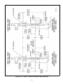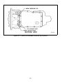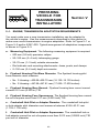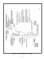
1
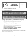
MECHANIC’S TIPS 1000/2000 PRODUCT FAMILIES ALLISON 4th GENERATION CONTROLS MT4007EN Mechanic’s Tips 2008 DECEMBER MT4007EN Allison Transmission Allison 4th Generation Controls 1000 and 2000 Product Families Printed in USA Copyright © 2009 Allison Transmission, Inc. NOTES 2 TABLE OF CONTENTS SECTION I 11 INTRODUCTION INTRODUCTION . . . . . . . . . . . . . . . . . . . . . . . . . . . . . . . . . . . . . .7 SECTION II PREVENTIVE MAINTENANCE 21 PERIODIC INSPECTION AND CARE . . . . . . . . . . . . . . . . . . . . . . . . . 13 22 PROGNOSTICS . . . . . . . . . . . . . . . . . . . . . . . . . . . . . . . . . . . . . 14 23 IMPORTANCE OF PROPER TRANSMISSION FLUID LEVEL . . . . . . . . . . . . 17 24 TRANSMISSION FLUID CHECK . . . . . . . . . . . . . . . . . . . . . . . . . . . . 17 25 KEEPING FLUID CLEAN . . . . . . . . . . . . . . . . . . . . . . . . . . . . . . . . 25 26 FLUID RECOMMENDATIONS . . . . . . . . . . . . . . . . . . . . . . . . . . . . . 25 27 TRANSMISSION FLUID AND FILTER CHANGE INTERVALS . . . . . . . . . . . . 27 28 TRANSMISSION FLUID CONTAMINATION . . . . . . . . . . . . . . . . . . . . . . 30 29 TRANSMISSION FLUID AND FILTER CHANGE PROCEDURE . . . . . . . . . . . 31 210 BREATHER . . . . . . . . . . . . . . . . . . . . . . . . . . . . . . . . . . . . . . . . 33 SECTION III REMOVING TRANSMISSION 31 DRAINING TRANSMISSION . . . . . . . . . . . . . . . . . . . . . . . . . . . . . . 34 32 DISCONNECTING CONTROLS . . . . . . . . . . . . . . . . . . . . . . . . . . . . 34 33 UNCOUPLING FROM DRIVELINE, ENGINE, AND VEHICLE . . . . . . . . . . . . 35 34 REMOVING THE TRANSMISSION . . . . . . . . . . . . . . . . . . . . . . . . . . . 35 35 REMOVING THE FLEXPLATE ADAPTER . . . . . . . . . . . . . . . . . . . . . . . 36 36 REMOVING OUTPUT FLANGE OR YOKE . . . . . . . . . . . . . . . . . . . . . . 36 SECTION IV TRANSMISSION PREPARATION 41 CHECKING INPUT COMPONENTS . . . . . . . . . . . . . . . . . . . . . . . . . . 37 42 INSTALLING OUTPUT FLANGE OR YOKE . . . . . . . . . . . . . . . . . . . . . . 37 43 INSTALLING PTO . . . . . . . . . . . . . . . . . . . . . . . . . . . . . . . . . . . . 38 44 INSTALLING FILL TUBE AND SEAL . . . . . . . . . . . . . . . . . . . . . . . . . . 42 45 CHECKING PLUGS AND OPENINGS . . . . . . . . . . . . . . . . . . . . . . . . . 44 SECTION V PREPARING VEHICLE FOR TRANSMISSION INSTALLATION 51 ENGINE, TRANSMISSION ADAPTATION REQUIREMENTS . . . . . . . . . . . . 46 3 52 CHECKING FLEXPLATE DRIVE ASSEMBLY . . . . . . . . . . . . . . . . . . . . . 50 53 CHASSIS AND DRIVELINE INSPECTION . . . . . . . . . . . . . . . . . . . . . . . 50 54 COOLER, FILTER, AND LINES . . . . . . . . . . . . . . . . . . . . . . . . . . . . . 51 55 CHECKING CONTROLS . . . . . . . . . . . . . . . . . . . . . . . . . . . . . . . . 52 SECTION VI INSTALLING TRANSMISSION INTO VEHICLE 61 HANDLING . . . . . . . . . . . . . . . . . . . . . . . . . . . . . . . . . . . . . . . . 56 62 MOUNTING TO ENGINE . . . . . . . . . . . . . . . . . . . . . . . . . . . . . . . . 56 63 INSTALLING TRANSMISSION MOUNTING COMPONENTS . . . . . . . . . . . . 58 64 COUPLING TO DRIVELINE . . . . . . . . . . . . . . . . . . . . . . . . . . . . . . . 58 65 CONNECTING POWER TAKEOFF CONTROLS . . . . . . . . . . . . . . . . . . . 59 66 CONNECTING PARKING BRAKE CONTROL . . . . . . . . . . . . . . . . . . . . . 59 67 CONNECTING COOLER . . . . . . . . . . . . . . . . . . . . . . . . . . . . . . . . 59 68 CONNECTING CONTROLS. . . . . . . . . . . . . . . . . . . . . . . . . . . . . . . 60 69 FILLING HYDRAULIC SYSTEM . . . . . . . . . . . . . . . . . . . . . . . . . . . . 61 610 INSTALLATION CHECKLIST . . . . . . . . . . . . . . . . . . . . . . . . . . . . . . 61 611 ROAD TEST AND VEHICLE OPERATION CHECKLIST . . . . . . . . . . . . . . . 63 SECTION VII CUSTOMER SERVICE 71 OWNER ASSISTANCE . . . . . . . . . . . . . . . . . . . . . . . . . . . . . . . . . 66 72 SERVICE LITERATURE . . . . . . . . . . . . . . . . . . . . . . . . . . . . . . . . . 66 4 TRADEMARK USAGE The following trademarks are the property of the companies indicated: • Allison DOCTM is a trademark of General Motors Corporation. • DEXRON® is a registered trademark of General Motors Corporation. • TranSyndTM is a trademark of Castrol Ltd. 5 WARNINGS, CAUTIONS, NOTES IT IS YOUR RESPONSIBILITY to be completely familiar with the warnings and cautions in this handbook. It is, however, important to understand that these warnings and cautions are not exhaustive. Allison Transmission could not possibly know, evaluate, and advise the service trade of all conceivable ways in which service might be done or of the possible hazardous consequences of each way. The vehicle manufacturer is responsible for providing information related to the operation of vehicle systems (including appropriate warnings, cautions, and notes). Consequently, Allison Transmission has not undertaken any such broad evaluation. Accordingly, ANYONE WHO USES A SERVICE PROCEDURE OR TOOL WHICH IS NOT RECOMMENDED BY ALLISON TRANSMISSION OR THE VEHICLE MANUFACTURER MUST first be thoroughly satisfied that neither personal safety nor equipment safety will be jeopardized by the service methods selected. Proper service and repair is important to the safe, reliable operation of the equipment. The service procedures recommended by Allison Transmission (or the vehicle manufacturer) and described in this handbook are effective methods for performing service operations. Some of these service operations require the use of tools specially designed for the purpose. The special tools should be used when and as recommended. Three types of headings are used in this manual to attract your attention. These warnings and cautions advise of specific methods or actions that can result in personal injury, damage to the equipment, or cause the equipment to become unsafe. WARNING: A warning is used when an operating procedure, practice, etc., if not correctly followed, could result in personal injury or loss of life. CAUTION: A caution is used when an operating procedure, practice, etc., if not strictly observed, could result in damage to or destruction of equipment. NOTE: A note is used when an operating procedure, practice, etc., is essential to highlight. 6 INTRODUCTION Section I 1–1. INTRODUCTION This manual is a mechanic’s reference for maintaining, removing, or installing Allison 4th Generation Controls, 1000 and 2000 Product Families transmission in a manner that assures satisfactory operation and long service life. All features of the transmission and the vehicle involved in installation procedures are discussed. The information presented will help the mechanic maintain, remove, or install the transmission in a manner that assures satisfactory operation and long service life. For additional detailed information, refer to the Service Manual (SM4006EN) and Troubleshooting Manual (TS3977EN). Unless specifically indicated otherwise, this handbook refers to all Allison 4th Generation Controls 1000 and 2000 Product Families transmissions. The differences between the various transmissions are explained as required. 7 Figure 1–1. 1000 and 2000 Product Families—Cross Section (With Park Pawl) 8 Figure 1–2. 2000 Product Family—Cross Section 9 Figure 1–3. 2000 Product Family—Cross Section (with Park Pawl) 10 Figure 1–4. 1000 and 2000 Product Families—LeftFront View 11 Figure 1–5. 1000 and 2000 Product Families—RightRear View 12 PREVENTIVE MAINTENANCE Section II 2–1. PERIODIC INSPECTION AND CARE a. Transmission Inspection. CAUTION: When cleaning the transmission, do not spray steam, water, or cleaning solution directly at the electrical connectors. Spraying steam, water, or cleaning solution at the electrical connectors can cause codes and cross talk. CAUTION: When cleaning the transmission, do not spray steam, water, or cleaning solution directly at the breather. Spraying steam, water, or cleaning solution at the breather can force water or cleaning solution into the transmission and contaminate the transmission fluid. Clean and inspect the exterior of the transmission at regular intervals. Severity of service and operating conditions determine the frequency of these inspections. Inspect the transmission for: • Loose bolts—transmission and mounting components. • Fluid leaks—repair immediately. • Loose, dirty, or improperly adjusted throttle sensor • Damaged or loose hoses. • Worn, frayed, or improperly routed electrical harnesses. • Worn or frayed electrical connectors. • Worn or outofphase driveline Ujoints and slip fittings. • Clogged or dirty breather (vent assembly). b. Vehicle Inspection. Check the vehicle cooling system occasionally for evidence of transmission fluid. Transmission fluid in the vehicle cooling system indicates a faulty oil cooler. 13 c. Welding. CAUTION: When welding on the vehicle: • DO NOT WELD on the vehicle without disconnecting from the TCM all control system wiring harness connectors. • DO NOT WELD on the vehicle without disconnecting TCM battery power and ground leads. • DO NOT WELD on any control components. • DO NOT CONNECT welding cables to any control components. A label describing onvehicle welding precautions ST2067EN is available from your authorized Allison service dealer and should be installed in a conspicuous place. A vehicle used in a vocation that requires frequent modifications or repairs involving welding must have an onvehicle welding label. 2–2. PROGNOSTICS a. 1000 and 2000 Product Families Service Prognostics. Service prognostics will be available beginning with MY09 vehicles and is only offered as a package at the option of the OEM (refer to the caution for vehicles not equipped for Prognostics). The Service Prognostics package requires the use of Allisonapproved TES 295 fluids and P/N 29539579 Control Main filter. Prognostics are used to predict the need for transmission maintenance. Transmission operating parameters monitored by the prognostics feature are: 1. Oil Life Monitor 2. Filter Life Monitor 3. Transmission Health Monitor NOTE: To determine if your vehicle has Prognostics enabled, observe operation of the OEMinstalled service indicator light. This light will illuminate for five seconds during start up in all equipped vehicles. When prognostics are enabled, the service indicator light will illuminate again for three seconds after the initial five second bulb check. If you are still unable to determine whether your vehicle has Prognostics enabled, consult with your OEM service department or an authorized Allison distributor or dealer. When a specified service threshold is detected for one of these parameters, the TRANS SERVICE indicator is illuminated to alert the operator to the need for action. Failure to attend to the service condition and reset the 14 TRANS SERVICE indicator within a defined operating period will result in the illumination of the CHECK TRANS light (in addition to the TRANS SERVICE light), indicating the increased probability that the service condition may/will develop into a more serious condition. The process for resetting the TRANS SERVICE indicator varies for each feature and is described in each of the following sections. The Allison DOCTM For PC–Service Tool may be used to review the current status of any of these features and a history of indicator resets. CAUTION: Transmission Prognostics features may be turned ON or OFF by a special transmission calibration and REQUIRES the use of Allisonapproved TES 295 fluids. If any other fluids or filters are used, prognostic features must be turned OFF. Prognostics information will not be accurate with any the use of any other transmission fluids and could result in improper maintenance activities resulting in transmission damage. If Prognostics is not programmed or is turned OFF, refer to the miles/hours/months fluid and filter change interval charts in the section of this book, or visit www.allisontransmission.com for a list of Allisonapproved TES 295 fluids, or read Service Tips 1099H for details. b. Oil Life Monitor. The TRANS SERVICE indicator will be illuminated, denoting a required change of the transmission fluid, when the remaining fluid life reaches approximately 2 percent (the parameter begins at 100 percent moving downward towards the lowest threshold). The TRANS SERVICE indicator will be lit steadily upon each initialization of the TCM, and will remain on steady for approximately two minutes after the initial selection of a drive range, until service is performed and the indicator is reset. The TRANS SERVICE indicator can be reset with the Allison DOCTM For PC–Service Tool. It may also be reset by selecting NDNDNRN on the shift selector, pausing briefly (less than 3 seconds) between each selector movement, with the ignition on and the engine not running. More details are provided in applicable Allison service literature for your specific transmission model. Failure to perform maintenance and reset the TRANS SERVICE indicator within the next 100 hours of transmission operation will result in the illumination of the TRANS SERVICE light (in addition to the TRANS SERVICE light). Any time this light is illuminated, the TCM will register a diagnostic code, which will require the use of Allison DOCTM For PC–Service Tool to clear the code. 15 In addition to viewing diagnostic codes, the Allison DOCTM For PC–Service Tool may also be used to display the amount of transmission operation from the initial service indication until the service reset. c. Filter Life Monitor. The TRANS SERVICE indicator will flash beginning with the first TCM initialization after reaching the time and mileage parameters, indicating that the filter has reached the end of its designed life. The indicator will continue to flash for two minutes after D (Drive) has been selected. Thereafter, the indicator will illuminate and flash upon each TCM initialization, continuing to flash for two minutes after the selection of D (Drive) each time, until service is performed and the indicator is reset. The TRANS SERVICE indicator can be reset with the Allison DOCTM For PC–Service Tool. It may also be reset by selecting NRNRNDN on the shift selector, pausing briefly (less than 3 seconds) between each selector movement, with the ignition on and the engine not running. More details are provided in applicable Allison service literature for your specific transmission model. Failure to perform maintenance and reset the TRANS SERVICE indicator after an additional 100 hours of transmission operation will result in the illumination of the CHECK TRANS light (in addition to the TRANS SERVICE light). Any time this light is illuminated, the TCM will register a diagnostic code, which will require the use of Allison DOCTM For PC–Service Tool to clear the code. In addition to viewing diagnostic codes, the Allison DOCTM For PC–Service Tool may also be used to display the amount of transmission operation from the initial service indication until the service reset. d. Transmission Health Monitor. The TRANS SERVICE indicator will be illuminated, indicating the need for clutch maintenance, when the remaining clutch life reaches approximately 10 percent, or if the running clearance exceeds a maximum value which may indicate a nonwearrelated issue. The indicator will be lit steadily upon initialization of the TCM, and will remain on steady at all times, continuing to operate in this manner until service is performed and the indicator is reset. If reset does not occur within 100 hours, the CHECK TRANS light will be illuminated (in addition to the TRANS SERVICE light) and the TCM will register a diagnostic code. The indicator will reset automatically upon elimination of the clutch clearance condition which initiated it. The indicator can also be reset using the Allison DOCTM For PC–Service Tool if necessary. The Allison DOCTM For PC–Service Tool may be used to display the amount of transmission operation from the initial service indication until the service reset. 16 2–3. IMPORTANCE OF PROPER TRANSMISSION FLUID LEVEL Transmission fluid cools, lubricates, and transmits hydraulic power. Always maintain proper fluid level. If fluid level is too low, the torque converter and clutches do not receive an adequate supply of fluid and the transmission overheats. If the level is too high, the fluid aerates—causing the transmission to shift erratically and overheat. Fluid may be expelled through the breather or dipstick tube when the fluid level is too high. 2–4. TRANSMISSION FLUID CHECK WARNING: For vehicles containing 1000 and 2000 Product Families transmissions with park pawl, each time you park the vehicle or leave the operator’s station with the engine running, do the following: 1. Bring the vehicle to a complete stop using the service brake. 2. Make sure that the engine is at low idle rpm. 3. Put the transmission in P (Park). 4. Engage the P (Park) range by slowly releasing the service brake. 5. Apply the emergency brake and/or parking brake, if present, and make sure it is properly engaged. 6. If the operator’s station will be unoccupied with the engine running, chock the wheels and take any other steps necessary to keep the vehicle from moving. If this procedure is not followed, the vehicle can move suddenly and you or others could be injured. 17 WARNING: For vehicles containing 2000 Product Family transmissions with autoapply parking brakes, each time you park the vehicle or leave the operator’s station with the engine running, do the following: 1. Bring the vehicle to a complete stop using the service brake. 2. Make sure that the engine is at low idle rpm. 3. Put the transmission in PB (AutoApply Parking Brake), and make sure that the parking brake is properly engaged. 4. Engage the P (Park) range by slowly releasing the service brake. 5. Apply the emergency brake, if present, and make sure it is properly engaged. 6. If the operator’s station will be unoccupied with the engine running, chock the wheels and take any other steps necessary to keep the vehicle from moving. If this procedure is not followed, the vehicle can move suddenly and you or others could be injured. WARNING: For vehicles containing 2000 Product Family transmissions without autoapply parking brakes, each time you park the vehicle or leave the operator’s station with the engine running, do the following: 1. Bring the vehicle to a complete stop using the service brake. 2. Make sure that the engine is at low idle rpm. 3. Put the transmission in N (Neutral). 4. Apply the emergency brake and/or parking brake, and make sure it is properly engaged. 5. If the operator’s station will be unoccupied with the engine running, chock the wheels and take any other steps necessary to keep the vehicle from moving. If this procedure is not followed, the vehicle can move suddenly and you or others could be injured. 18 NOTE: For accurate fluid level checks, be sure that the fill tube and dipstick meet Allison Transmission specifications. Requirements for the short and medium fill tube and dipstick are shown in Figure 2–1; the long fill tube and dipstick are shown in Figure 2–2. When checking a short or medium dipstick calibration: 1. Remove the oil pan. 2. Take measurements from the oil pan splitline. When checking a long dipstick calibration: 1. Be sure the dipstick contacts the oil pan surface as shown in Figure 2–2. 2. Take measurements from the end of the dipstick. 19 Figure 2–1. Short and Medium Fill Tube and Dipstick Requirements 20 Figure 2–2. Long Fill Tube and Dipstick Requirements 21 a. Manual Fluid Check Procedure. Clean all dirt from around the top of the fluid fill tube before removing the dipstick. Do not allow dirt or foreign matter to enter the transmission. Dirt or foreign matter in the hydraulic system may cause undue wear of transmission parts, make valves stick, and clog passages. Check the fluid level using the following procedure and report any abnormal fluid levels to your service management. b. Cold Check Procedure. The purpose of the cold check is to determine if the transmission has enough fluid to be operated safely until a hot check can be made. CAUTION: The fluid level rises as fluid temperature increases. DO NOT fill above the “COLD CHECK” band if the transmission fluid is below normal operating temperatures. 1. Park vehicle as follows: a. For vehicles containing 1000 and 2000 Product Families transmissions with park pawl: (1) Bring the vehicle to a complete stop on a level surface using the service brake. (2) Make sure that the engine is at low idle rpm. (3) Put the transmission in P (Park). (4) If a parking brake is present, apply the parking brake. Make sure that the parking brake is properly engaged. (5) Engage the P (Park) range by slowly releasing the service brake. (6) Apply the emergency brake, if present, and make sure it is properly engaged. (7) Chock the wheels and take any other steps necessary to keep the vehicle from moving. b. For vehicles containing 2000 Product Family transmissions with autoapply parking brakes: (1) Bring the vehicle to a complete stop on a level surface using the service brake. (2) Make sure that the engine is at low idle rpm. (3) Put the transmission in PB (AutoApply Parking Brake). Make sure that the parking brake is properly engaged. (4) Apply the emergency brake, if present, and make sure it is properly engaged. 22 (5) Chock the wheels and take any other steps necessary to keep the vehicle from moving. c. For vehicles containing 2000 Product Family transmissions without autoapply parking brakes: (1) Bring the vehicle to a complete stop on a level surface using the service brake. (2) Make sure that the engine is at low idle rpm. (3) Put the transmission in N (Neutral). (4) Apply the emergency brake and/or parking brake and make sure they are properly engaged. (5) Chock the wheels and take any other steps necessary to keep the vehicle from moving. 2. Run the engine for at least one minute. Apply the service brakes and shift to D (Drive), then to N (Neutral), and then shift to R (Reverse) to fill the hydraulic system. Finally, shift to P (Park) or PB (AutoApply Parking Brake), if available, or N (Neutral) and allow the engine to idle 500–800 rpm. Slowly release the service brakes. 3. With the engine running, remove the dipstick from the tube and wipe the dipstick clean. 4. Insert the dipstick into the tube and remove. Check the fluid level reading. Repeat the check procedure to verify the reading. 5. If the fluid level is within the “COLD CHECK” band, the transmission may be operated until the fluid is hot enough to perform a “HOT RUN” check. If the fluid level is not within the “COLD CHECK” band, add or drain as necessary to bring it to the middle of the “COLD CHECK” band. 6. Perform a hot check at the first opportunity after the normal operating sump temperature of 71°C–93°C (160°F–200°F) is reached. c. Hot Check Procedure. CAUTION: The fluid must be hot to allow an accurate check. The fluid level rises as temperature increases. 1. Operate the transmission in D (Drive) until normal operating temperatures are reached: • Sump temperature 71°C–93°C (160°F–200°F) • Converterout temperature 82°C–104°C (180°F–220°F) • If the transmission temperature gauge is not present, check fluid level when the engine water temperature gauge has stabilized 23 and the transmission has been operated under load for at least one hour. 2. Park vehicle as follows: a. For vehicles containing 1000 and 2000 Product Family transmissions with park pawl: (1) Bring the vehicle to a complete stop on a level surface using the service brake. (2) Make sure that the engine is at low idle rpm. (3) Put the transmission in P (Park). (4) If a parking brake is present, apply the parking brake. Make sure that the parking brake is properly engaged (5) Engage the P (Park) range by slowly releasing the service brake. (6) Apply the emergency brake, if present, and make sure it is properly engaged. (7) Chock the wheels and take any other steps necessary to keep the vehicle from moving. b. For vehicles containing 2000 Product Family transmissions with autoapply parking brakes: (1) Bring the vehicle to a complete stop on a level surface using the service brake. (2) Make sure that the engine is at low idle rpm. (3) Put the transmission in PB (AutoApply Parking Brake). Make sure that the parking brake is properly engaged. (4) Apply the emergency brake, if present, and make sure it is properly engaged. (5) Chock the wheels and take any other steps necessary to keep the vehicle from moving. c. For vehicles containing 2000 Product Family transmissions without autoapply parking brakes: (1) Bring the vehicle to a complete stop on a level surface using the service brake. (2) Make sure that the engine is at low idle rpm. (3) Put the transmission in N (Neutral). (4) Apply the emergency brake and/or parking brake and make sure they are properly engaged. 24 (5) Chock the wheels and take any other steps necessary to keep the vehicle from moving. 3. With the engine running, remove the dipstick from the tube and wipe clean. 4. Insert the dipstick into the tube until it stops. Then remove it. Check fluid level reading. Repeat the check procedure to verify the reading. NOTE: Safe operating level is within the “HOT RUN” band on the dipstick Figure 2–1 and Figure 2–2. The width of the “HOT RUN” band represents approximately 1.0 liter (1.06 quart) of fluid at normal operating sump temperature. 5. If the fluid level is not within the “HOT RUN” band, add or drain as necessary to bring the fluid level to within the “HOT RUN” band. d. Consistency of Readings. Always check the fluid level at least twice, with the engine running. Consistency (repeatable readings) is important to maintaining accuracy of the readings. If inconsistent readings persist, check the transmission breather to be sure it is clean and unclogged. If readings are still inconsistent, contact your nearest Allison distributor or dealer. 2–5. KEEPING FLUID CLEAN Prevent foreign material from entering the transmission by using clean containers, fillers, etc. Lay the dipstick in a clean place while filling the transmission. CAUTION: Containers or fillers that have been used for antifreeze solution or engine coolant must NEVER be used for transmission fluid. Antifreeze and coolant solutions contain ethylene glycol which, if put into the transmission, can cause the clutch plates to fail. 2–6. FLUID RECOMMENDATIONS CAUTION: DEXRON®VI is restricted to 1000/2000 transmissions beginning with serial number 6310670488. Hydraulic fluids (oils) used in the transmission are important influences on transmission performance, reliability, and durability. Only fluids meeting TES 295, TES 389, DEXRON®III, or DEXRON®VI fluid specifications are acceptable for use in 1000 and 2000 Product Families transmissions. TranSyndTM is a full synthetic transmission fluid developed by Allison 25 Transmission and Castrol Ltd. and is fully qualified to the GM DEXRON®VI specifications NOTE: Allison Prognostics must only be used with Allisonapproved TES 295 fluids. To make sure the fluid is qualified for use in Allison transmissions, check for a TES 389 or TES 295 fluid license or approval numbers on the container, or consult the lubricant manufacturer. Consult your Allison Transmission dealer or distributor before using other fluid types. CAUTION: Disregarding minimum fluid temperature limits can result in transmission malfunction or reduced transmission life. When choosing the optimum viscosity grade of fluid, duty cycle, preheat capabilities, and/or geographical location must be taken into consideration.Table 2–1 lists the minimum fluid temperatures at which the transmission may be safely operated without preheating the fluid. Preheat with auxiliary heating equipment or by running the equipment or vehicle with the transmission in P (Park) or PB (AutoApply Parking Brake), if available, or N (Neutral) for a minimum of 20 minutes before attempting range operation. Table 2–1. Transmission Fluid Operating Temperature Requirements Ambient Temperature Below Which Preheat is Required Viscosity Grade DEXRON®VI or Celsius Fahrenheit –25 –13 –35 –31 TES389 TranSyndTM or TES295 Ref. SIL 10TR99 NOTE: Transmission ranges available and torque converter clutch operations are limited when the transmission fluid temperature is below –25°C (–13°F). 26 2–7. TRANSMISSION FLUID AND FILTER CHANGE INTERVALS CAUTION: Transmission fluid and filter change frequency is determined by the severity of transmission service. More frequent changes may be necessary than recommended in the general guidelines when operating conditions create high levels of contamination or overheating. a. Frequency. New vehicles delivered from the OEM with a mixture of Allisonapproved TES 295 fluid and nonapproved fluid, or TES 389 Allisonapproved fluid must follow fluid/filter change recommendations outlined in Table 2–2. If the customer fills the transmission with Allisonapproved TES 295 fluid or TES 295 equivalent, the change recommendations of Table 2–2 must be followed. Upon the next oil change, if the customer reinstalls Allisonapproved TES 295 fluid, the fluid/filter change recommendations outlined in Table 2–3 may be used. The recommendations in Table 2–3 are based upon Allison fluid change procedures and the transmission containing 100 percent of Allisonapproved TES 295 fluid. For transmissions that contain a mixture of Allisonapproved TES 295 fluid and nonapproved fluids, refer to Table 2–2. NOTE: Fluid Exchanging Machines are not recommended or recognized due to variation and inconsistencies that may not guarantee removal of 100 percent of the used fluid. Table 2–2 through Table 2–3, Recommended Fluid/Filter Change Intervals, is a general guide for fluid and filter change intervals. Allison Transmission requires an initial filter change for the SpinOn Control Main Filter during the first 5000 miles (8000 km) or 200 hours, whichever comes first. Refer to the Recommended Fluid and Filter Change Intervals schedules for recommendations. The transmission sump filter is permanent and does not require replacement except at overhaul. Severe Vocations include armored car, automobile transporter, beverage delivery, food distribution, general freight, line haul, livestock hauler, moving/storage, oneway rental truck, recycling, shorthaul/LTL, and pickup and delivery. Highway Series models are also acceptable for poultrybus applications when truck chassis are utilized. General Vocations include all other vocations. Local conditions, severity of operation or duty cycle may 27 require more or less frequent fluid change intervals that differ from the published recommended fluid change intervals of Allison Transmission. The following tables are given only as a general guide for fluid and filter change intervals. Table 2–2. Schedule 1. Recommended Fluid and Filter Change Intervals (AllisonApproved NonTES 295 Fluids) Filters Vocation Fluid* Control Main** General 50,000 miles (80 000 km) 24 months 2000 hours 50,000 miles (80 000 km) 24 months 2000 hours Severe 12,000 miles (20 000 km) 6 months 500 hours 12,000 miles (20 000 km) 6 months 500 hours *Allisonapproved Internal Lube/Auxiliary Overhaul 50,000 miles (80 000 km) 24 months 2000 hours Overhaul 12,000 miles (20 000 km) 6 months 500 hours nonTES 295 fluid is defined as the quantity of oil remaining in the transmission after a standard fluid change combined with the quantity of Allisonapproved TES 295 fluid that is required to fill the transmission to the proper level. A mixture of Allisonapproved TES 295 fluid vs. nonTES 295 fluids other than as defined in this paragraph does not meet the requirements that permit the eligibility for the recommendations given in Schedule 2. **Control Main Spinon Filters Only—Initial 10,000 miles (16 000 km) or first engine oil change, whichever comes first. 28 Table 2–3. Schedule 2. Recommended Fluid and Filter Change Intervals (100 Percent Concentration of AllisonApproved TES 295 Fluids) Filters Control Main* Vocation Fluid General 150,000 miles (240 000 km) 48 months 4000 hours 50,000 miles (80 000 km) 24 months 2000 hours Severe 75,000 miles (120 000 km) 36 months 3000 hours 50,000 miles (80 000 km) 24 months 2000 hours Internal Lube/Auxiliary Overhaul 50,000 miles (80 000 km) 24 months 2000 hours Overhaul 50,000 miles (80 000 km) 24 months 2000 hours *Control Main Spinon Filter Only—Initial 10,000 miles (16 000 km), or 400 hours, whichever comes first. Table 2–4. Schedule 3. Recommended Fluid and Filter Change Intervals (Allison Prognostics “ON” Beginning in MY09) Filters Vocation Fluid* Control Main** General or Severe Change fluid when indicated by controller or 48 months, whichever comes first. Change filter when indicated by controller or 48 months, whichever comes first. Internal Lube/Auxiliary Change filter when indicated by controller Overhaul or 48 months, whichever comes first. *Allison Prognostics must only be used with Allisonapproved TES 295 fluid. Prognostics must only be used with Allison P/N 29539579 control main spinon filter. Control Main Spinon Filters Only—Initial 10,000 miles (16 000 km) or 400 hours, whichever comes first. **Allison b. Abnormal Conditions. Transmissions used in high duty cycle applications should use fluid analysis to be certain that a proper fluid change interval is established. Transmission fluid must be changed whenever there is evidence of dirt or a high temperature condition. A high temperature condition is indicated by the transmission fluid being discolored or having a strong odor, or by fluid analysis. Local conditions, severity of operation, or duty cycle may require more or less frequent fluid or filter change intervals. 29 c. Fluid Analysis. Transmission protection and fluid change intervals can be optimized by monitoring fluid oxidation according to the tests and limits shown in Table 2–5. Consult your local telephone directory for fluid analysis firms. To make sure of consistent and accurate fluid analysis, use only one fluid analysis firm. Refer to GN2055EN, Technician’s Guide for Automatic Transmission Fluid for additional information. Table 2–5. Fluid Analysis Measurement Limits Test Limit Viscosity ±25 percent change from new fluid Total Acid Number +3.0* change from new fluid (Ref. SIL 17TR96) *mg of potassium hydroxide (KOH) to neutralize a gram of fluid 2–8. TRANSMISSION FLUID CONTAMINATION a. Fluid Examination. At each fluid change, examine the drained fluid for evidence of dirt or water. A normal amount of condensation (not to exceed 0.2 percent) will appear in the fluid during operation. b. Water. Obvious water contamination of the transmission fluid or transmission fluid in the cooler (heat exchanger) water indicates a leak between the water and fluid areas of the cooler. Inspect and pressure test the cooler to confirm the leak. Replace leaking coolers. NOTE: Cooler water can also be contaminated by engine oil; be sure to locate the correct source of cooler water contamination. c. Engine Coolant. CAUTION: Engine coolant in the transmission hydraulic system requires immediate action to prevent malfunction and possible serious transmission damage. Completely disassemble, inspect, and clean the transmission. Remove all traces of the coolant and varnish deposits resulting from engine coolant contamination (ethylene glycol). 30 d. Metal. Metal particles in the fluid (except for the minute particles normally trapped in the oil filter) indicate internal transmission damage. If these particles are found in the sump, the transmission must be disassembled and closely inspected to find their source. Metal contamination requires complete transmission disassembly. Clean all internal and external hydraulic circuits, cooler, and all other areas where the particles could lodge. CAUTION: After flushing the cooler, be sure to check the external cooler circuit restriction. If circuit pressure drop is above specification, the cooler has excessive trapped particles and must be replaced. NOTE: When equipment to flush the oil cooler is not available, install a filter in the cooler line between the oil cooler and the transmission “from cooler” port. The cooler circuit pressure drop specifications must still be met (see AS64071 or AS64072 in the Allison Sales Tech Data book SA3018EN. Frequent initial changes of this filter element may be required as debris is flushed out of the oil cooler circuit. Closely monitoring change in cooler circuit pressure drop will indicate when a filter change is needed. 2–9. TRANSMISSION FLUID AND FILTER CHANGE PROCEDURE a. Drain Fluid. 1. Drain the fluid when the transmission is at normal operating sump temperature: 71°C to 93°C (160°F to 200°F) . Hot fluid flows quicker and drains more completely. 2. Remove the drain plug from the oil pan and allow the fluid to drain into a suitable container. 3. Examine the fluid as described in 2–8. TRANSMISSION FLUID CONTAMINATION. b. Replace ControlMain Filter. Refer to Figure 2–3 during the following procedure. 1. Remove the controlmain filter by rotating it in the counterclockwise direction. Use a standard straptype filter wrench. 2. Remove the magnet from the filter attachment tube or from the top of the filter element. 3. Clean any metal debris from the magnet. Report any metal pieces larger than dust to your service management. 4. Reinstall the magnet onto the filter attachment tube. 31 5. Lubricate the gasket on the controlmain filter with transmission fluid. 6. Install, by hand, the controlmain filter until the gasket on the controlmain filter touches the converter housing or cooler manifold. CAUTION: Turning the controlmain filter more than ONE FULL TURN after gasket contact will damage the filter. 7. Turn the filter ONE FULL TURN ONLY after gasket contact. 8. Reinstall the drain plug and sealing washer. Tighten the drain plug to 30–40 N∙m (22–30 lb ft) . Figure 2–3. Replacing ControlMain Filter 32 c. Refill Transmission. Refer to Table 2–6 for fluid refill quantities. The amount of refill fluid is less than the amount used for the initial fill. Fluid remains in the external circuits and transmission cavities after draining the transmission. After refill, check the fluid level using the procedure described in 2–4. TRANSMISSION FLUID CHECK. NOTE: Quantities listed are approximations and do not include external lines and cooler hose. Table 2–6. Transmission Fluid Capacity Sump Initial Fill Refill Liters Quarts Liters Quarts Standard 14 14.8 10 10.6 Shallow 12 12.7 7 17 2–10. BREATHER a. Location and Purpose. The breather is located on top of transmission converter housing. The breather prevents air pressure buildup within the transmission and its passage must be kept clean and open. b. Maintenance. The amount of dust and dirt encountered will determine the frequency of breather cleaning. Use care when cleaning the transmission. CAUTION: When cleaning the transmission, do not spray steam, water, or cleaning solution directly at the electrical connectors. Spraying steam, water, or cleaning solution at the electrical connectors can cause codes and cross talk. CAUTION: When cleaning the transmission, do not spray steam, water, or cleaning solution directly at the breather. Spraying steam, water, or cleaning solution at the breather can force water or cleaning solution into the transmission and contaminate the transmission fluid. NOTE: Fluid loss out of the breather in cold ambient conditions during engine start may be remedied by venting the fill tube (refer to SIL 61k2k06). 33 REMOVING TRANSMISSION Section III 3–1. DRAINING TRANSMISSION Drain the transmission fluid before removing the transmission from the vehicle. 1. Remove the drain plug from the oil pan. Examine the drained fluid for evidence of contamination (2–8. TRANSMISSION FLUID CONTAMINATION). Reinstall the drain plug. 2. Remove the transmission fill tube if it interferes with transmission removal. Plug the fill tube hole in the main housing to keep dirt from entering the transmission. NOTE: A significant amount of fluid may drain from the hydraulic lines when they are disconnected from the transmission. 3. Disconnect all hydraulic lines from the transmission. Remove the lines from the vehicle if they interfere with transmission removal. Plug all openings to keep dirt from entering the hydraulic system. 3–2. DISCONNECTING CONTROLS 1. Disconnect the external wiring harness at the feedthrough harness connector. Loosen the bolt that retains the 24way feedthrough connector to the transmission. Refer to Figure 1–4 or Figure 1–5. Prevent dirt or moisture from entering a disconnected connector. Position the wiring harness so it does not interfere with transmission removal. 2. Disconnect linkage from the customerfurnished transmission shift lever. Position the disconnected linkage so it does not interfere with transmission removal. Leave the shift lever on the transmission. 3. If PTO(s) is (are) used, disconnect the PTO(s) wiring harness(es). 4. If parking brake is present, disconnect linkage. 34 3–3. UNCOUPLING FROM DRIVELINE, ENGINE, AND VEHICLE WARNING: Chock wheels to prevent vehicle from moving when driveline is disconnected. This is not necessary if vehicle is on a lift or jackstands. 1. Disconnect the vehicle drive shaft from the transmission output flange or yoke. Position the disconnected shaft to avoid interference when removing the transmission. 2. If PTO equipped, disconnect PTO connections such as: a. PTO hydraulic hoses b. PTOpowered equipment drive shaft 3. If transmission mountings support the rear of the engine, place a jack or other support under the engine. 4. Securely support the transmission with a hoist, jack, or other suitable removal equipment. NOTE: It may be necessary to remove an engine flywheel housing access cover to remove flexplate or flexplate adapter bolts. This is the engine to transmission connection. 5. Remove all bolts, nuts, washers, spacers, and supports that attach the transmission to the vehicle and the engine. 3–4. REMOVING THE TRANSMISSION CAUTION: Do not pull the transmission away from the torque converter assembly. The torque converter drive cover must be entirely free of any restraint by the flexplate drive or crankshaft pilot when the transmission separates from the engine. WARNING: Be sure the torque converter is moving rearward with the transmission as it is removed. Do not allow the torque converter to become disengaged from the oil pump or to fall completely out of the transmission causing damage and/or personal injury. 1. Move the transmission away from the engine, approximately 34.6 mm (1.36 inch) for a number 2 flywheel housing or 44.2 mm (1.74 inch) for a number 3 flywheel housing, until it is completely clear of the engine. If used, remove the adapter ring and/or gasket. 35 2. Raise or lower the transmission as necessary to remove it from the vehicle. 3–5. REMOVING THE FLEXPLATE ADAPTER 1. Remove the flexplate adapter, if present, from the front of the torque converter. This part will be needed for transfer if a replacement transmission is being installed. WARNING: Handle the transmission carefully whenever the torque converter retaining bracket is not present. NEVER tilt the converter end down or the torque converter can slide forward, disengaging the oil pump, or can fall completely out of the transmission causing damage and/or personal injury. 2. Attach a torque converter retaining bracket at the earliest opportunity. The bracket keeps the torque converter from sliding out of engagement with the oil pump or from falling off completely and being damaged or causing personal injury. 3–6. REMOVING OUTPUT FLANGE OR YOKE If replacing the transmission, you may need to transfer the output flange or yoke to the replacement transmission. The output flange or yoke is retained by one 1/220 x 23/4 inch flangedhead bolt. 36 TRANSMISSION PREPARATION Section IV 4–1. CHECKING INPUT COMPONENTS a. Bolt Holes. Check all bolt holes on the front of the transmission and rear of the engine that are used in connecting the transmission to the engine. The threads must be undamaged and the holes free of chips or foreign material. b. Pilot Boss. Check the pilot boss (at the center of the flywheel) for damage or raised metal that prevents free entry into the crankshaft hub (or adapter). c. Starter Ring Gear. Check the starter ring gear for excessive wear or damage. d. Transmission Mounting Flange. Check the transmission mounting flange for raised metal, dirt, or if used, pieces of gasket material. e. TransmissiontoEngine Mounting. Inspect the transmissiontoengine mounting flange for raised metal, burrs, or pieces of gasket material (if used). Remove any of these defects. Inspect the threaded holes for damaged threads. 4–2. INSTALLING OUTPUT FLANGE OR YOKE a. Output Oil Seal. Check the output oil seal for leaks or damage. Refer to GN4008EN, InChassis Maintenance, for replacement instructions. If not replacing the oil seal, lubricate it with hightemperature grease or transmission fluid. CAUTION: DO NOT attempt to polish the oil seal contact surface on the flange or yoke. Scratches or machinetype lead can cause the seal to leak. b. Check Flange or Yoke. Check each flange or yoke for damage or wear. The oil seal contact surface must be smooth and regular to prevent oil leaking past the seal. Rotate the flange after installation to check for binding. 37 c. Install Output Flange or Yoke. CAUTION: Be sure that the flange, output shaft and retaining hardware are clean. Care must be exercised to avoid transmission output seal or journal damage. Check to verify that the seal is free of tears and cuts. Nicks and scratches must not exist on the leadin chamfer or seal journal section of the output flange or yoke. 1. Lubricate the splines of the output shaft and the oil seal assembly with transmission fluid or oilsoluble grease. CAUTION: Do not use a hammer or other similar tool to force the flange/yoke onto the shaft. Forcing the flange/yoke onto the shaft may result in transmission damage. 2. Start the yoke/flange assembly onto the output shaft, ensuring that the splines are properly engaged and slide freely. Push the yoke/flange assembly into the rear cover module. 3. Install a new output shaft sealing washer and the output shaft bolt. CAUTION: Use of an impact wrench requires the retention of the yoke/flange to prevent internal transmission damage. 4. Tighten the output shaft bolt to 108–136 N∙m (80–100 lb ft). 5. Rotate the yoke/flange assembly by hand to check for binding, interference, and runout. 4–3. INSTALLING PTO Access to the PTO mounting pads and the space available to maneuver the transmission determine whether the PTO should be installed before or after the transmission is installed. CAUTION: DO NOT use cork or other soft gaskets to install the PTO. Use only the shims/gaskets listed in the Sales Tech Data Book on the Allison Extranet. NOTE: DO NOT use sealing compounds—they are usually incompatible with automatic transmission fluid. 38 a. Install Guide Pins. Guide pins are included in the PTO manufacturers installation kit. Determine the required position of the guide pins in relation to the mounted position of the PTO. Install two headless guide pins into the main housing PTO pad. Tighten the pins. b. Install Gasket. Install the special gasket over the guide pins—ribbed surface away from the transmission. c. Mount the PTO. CAUTION: M10 bolts must be used to attach the PTO to the transmission. Inch series threads (0.37516 UNC) will damage the transmission main housing. Mount the PTO on the guide pins or studs provided in the PTO kit. Mesh the PTOdriven gear with the transmission PTO drive gear. Retain the PTO by installing a bolt in the top bolt hole. Install the remaining bolts and nuts, if used. When nuts are not used, two bolts replace the guide pins. Tighten all bolts to 57–68 N∙m (42–50 lb ft). Tighten nuts to manufacturers specifications. Be sure that the PTO backlash meets manufacturers requirements. d. Connect PTO Lube, if required. Some PTOs require pressure lubrication. When needed, tap into the cooler return fitting or line at the transmission converter housing (refer to Figure 4–1). NOTE: It is not acceptable to use the transmission main pressure for PTO lubrication. There is only one acceptable use of transmission main pressure for accessories—that being to control engagement of the PTO clutch. This practice is permitted for this function only because there is no flow (the fluid is deadheaded). An orifice of 0.81 mm (0.032 inch) must be present in the line to control the amount of fluid diverted from the transmission. Some PTO assemblies contain internal restrictions equivalent to the required orifice (check with the PTO manufacturer for lubrication needs and the orifice installation). This connection can be made later if the lube line will interfere with transmission installation. Refer to Figure 4–2 which shows this connection schematically. 39 Figure 4–1. Cooler Port and Main Pressure Tap Location 40 Figure 4–2. PTO Lube Plumbing Schematic 41 Figure 4–3. PTO Clutch Pressure Plumbing Schematic e. Connect PTO Clutch Feed, if required. Some PTOs are clutchapplied. Use transmission main pressure from the main pressure tap for applying the PTO clutch. Refer to Figure 4–1 for the location of the main pressure tap and Figure 4–3 for a typical plumbing schematic when this feature is needed. This connection can be made later if the clutch apply line will interfere with transmission installation. 4–4. INSTALLING FILL TUBE AND SEAL a. Location. The fill tube may be mounted on either the right or left side. The unused fill tube provision must have a plug to fill the tube opening. 42 CAUTION: Install the fill tube bracket with the correct length M8 selftapping screw which is 24.0 mm (0.95 inch). A screw that is too long may cause cracks and leaks in the main housing. Refer to AS64065 in the Allison Sales Tech Data Book on the Allison Extranet for the correct screw specifications. b. Installation. If the fill tube will interfere with the installation of the transmission, delay this step until after the transmission is in the vehicle. Install the fill tube seal into the main housing. Insert the fill tube through the seal until the shoulder at the bottom of the fill tube contacts the seal. Align the tube bracket with its bolt location. Install the fill tube bolt and tighten until it is firmly seated against the bracket. 43 Figure 4–4. 4–5. CHECKING PLUGS AND OPENINGS Carefully check all sides and the bottom of the transmission for loose or missing plugs. a. Pressure Plugs. Check that .4375–20 UNF2A pressure plugs are tightened to 10–13 N∙m (7–10 lb ft). b. Fluid Drain Plug. Check that the drain plug is tightened to 30–40 N∙m (22–30 lb ft) . c. Tachograph Plug. If present, tighten to 60–67 N∙m (44–49 lb ft). 44 d. Cleanliness. Check the openings into which the cooler lines connect for deformities or obstructions. Check the transmission electrical connectors for cleanliness. Clean electrical connectors with LPS cleaner only (refer to Service Information Letter 17TR94). 45 PREPARING VEHICLE FOR TRANSMISSION INSTALLATION Section V 5–1. ENGINE, TRANSMISSION ADAPTATION REQUIREMENTS You must make sure a new transmission installation can be adapted to the vehicle’s engine. Use the measurements described in this section to make sure correct transmissiontoengine adaptation. Refer to Figure 5–1 or Figure 5–2 and/or AS67–020. Typical arrangement of adaptation components is shown in Figure 5–3. a. Measuring Equipment. The following measuring equipment is required: • 600 mm (24 inch) precision caliper • 50–100 mm (2–4 inch) telescoping gauge • 25–76 mm (1–3 inch) outside micrometer • Dial indicator and mounting attachments—base, posts, and clamps • 0–150 mm (0–6 inch) depth micrometer b. Flywheel Housing Pilot Bore Diameter. The flywheel housing pilot bore diameter must measure: • No. 3 Housing—409.58–409.70 mm (16.125–16.130 inches) • No. 2 Housing—447.68–447.81 mm (17.625–17.630 inches) c. Flywheel Housing Bore Runout. Flywheel housing bore runout cannot exceed 0.51 mm (0.020 in) TIR. d. Flywheel Housing Face Squareness. The flywheel housing face cannot be outofsquare more than 0.51 mm (0.020 inch) TIR. e. Crankshaft Hub Pilot or Adapter Diameter. The crankshaft hub pilot or hub adapter pilot diameter must measure between 43.26–43.31 mm (1.703–1.705 inch). f. Crankshaft Hub Pilot or Adapter Squareness. The crankshaft hub or hub adapter cannot be outofsquare more than 0.013 mm (0.0005 inch) TIR per inch of diameter. 46 Figure 5–1. Engine Adaptation (No. 3 Housing) 47 Figure 5–2. Engine Adaptation (No. 2 Housing) 48 Figure 5–3. Typical Arrangement of Adaptation Components 49 g. Crankshaft Hub Pilot or Adapter Concentricity. The crankshaft hub pilot or the hub adapter pilot concentricity cannot exceed 0.25 mm (0.010 inch) TIR. h. Flexplate Bolt Hole Flatness. Flexplate flatness must be 0.76 mm (0.030 inch) TIR, or less, when measured at 292 mm (11.5 inch) diameter. i. Torque Converter Axial Location. This is controlled by the engine physical adaptation. Using a depth gauge, measure from the face of the engine flywheel housing to the face at the 292.1 mm (11.50 inches) diameter. The torque converter axial location should measure: • No. 3 Housing—40.15–44.21 mm (1.581–1.741 inches) • No. 2 Housing—30.50–34.56 mm (1.201–1.361 inches) 5–2. CHECKING FLEXPLATE DRIVE ASSEMBLY a. Flexplate Inspection. Check the flexplate for cracks, distortion, or elongated bolt holes. Replace a worn or damaged flexplate. b. Engine Crankshaft End Play. Make sure engine crankshaft end play is within the engine manufacturer’s specifications. NOTE: When assembling the flexplate to the crankshaft hub or hub adapter, make sure the outer flexplate bolt holes are aligned. NOTE: When assembling the flexplate to the crankshaft hub or hub adapter, make sure the outer flexplate bolt holes are aligned. c. Flexplate Assembly Installation. Install the flexplate onto the engine crankshaft hub using the bolts and torque values specified for that engine. Refer to Figure 5–1, Figure 5–2, or Figure 5–3 for the proper position of an installed flexplate. 5–3. CHASSIS AND DRIVELINE INSPECTION Inspect the chassis and driveline components for the following conditions, and correct them as appropriate. • Transmission mounts—broken or wornout • Bolts and other hardware—damaged, missing, or incorrect • Isolators (rubber mounts)—damaged or missing 50 • Driveline angles—runout, or balance which does not conform to the manufacturer’s recommendations • Driveline yoke slip joints: – freedom of movement – damaged or wornout – correctly lubricated – correctly indexed • Driveline midship or hanger bearings—damaged or misaligned • Universal joints: – freedom of movement – damaged or wornout – correctly lubricated – correctly indexed • Vehicle differential backlash—manufacturer’s specification • Universal joint coupling—alignment and differential damage • Crossframe members and rear support members—condition and location • PTOdriven equipment shafts and couplings—damaged or misaligned • Auxiliary transmission: – shaft alignment – alignment of yoke or flange – backlash – fluid leaks 5–4. COOLER, FILTER, AND LINES a. Inspection. Perform the following and correct any faulty conditions: • Transmission fluid cooler and related coolant lines: – Check for contamination—clean and flush as necessary – Inspect for deterioration – Inspect for faulty connectors or kinks – Clean and flush transmission fluid cooler, both coolant and oil sides using J 46550A Transmission Cooler Kwik Cart. Pressure check both sides using a 276 kPa (40 psi) air supply. • Hydraulic lines: 51 – Check for contamination—clean and flush as necessary – Inspect for deterioration – Inspect for faulty connectors or kinks b. After Overhaul. A complete cleanup of the transmission system after an overhaul cannot be assumed. Repeated cleaning and flushing may not remove all debris from the transmission fluid cooler system. Refer to GN4008EN, InChassis Maintenance, for cooler flushing procedure. NOTE: When equipment to flush the oil cooler is not available, install a filter in the cooler line between the oil cooler and the transmission “from cooler” port. The cooler circuit pressure drop specifications must still be met. For 1000 Product Family transmissions, pressure drop must not exceed 241 kPa @ 22.7 liters/min flow (35 psi @ 6.0 gal/min). For 2000 Product Family transmissions, pressure drop must not exceed 159 kPa @ 30.3 liters/min flow (23 psi @ 8.0 gal/min). Frequent initial changes of this filter element may be required as debris is flushed out of the oil cooler circuit. Closely monitoring change in cooler circuit pressure drop will indicate when a filter change is needed. 5–5. CHECKING CONTROLS a. Inspection. Inspect the following and correct any faulty conditions: • Shift selector: – improper operation – poor electrical connections – improper harness routing • Cab and chassis wiring harness: – poor electrical connections – frayed insulation – wiring damage • Throttle sensor components, if present: – freedom of movement – improper routing – bellows damage – improper or loose cable mounting 52 • PTO controls, if present: – damage – wear – improper operation – lubrication – electrical harness connections and wiring damage • Temperature gauge: – capillary tube damage (if used) – sensor damage • Fluid pressure gauge tubing: – damage – kinks – improper routing b. Throttle Position Sensor (TPS) Adjustment—Using Diagnostic Tool. When properly installed by the equipment manufacturer, the TPS, if used, should not require adjustment. If TPS adjustment is necessary, confirm that it has been installed to Allison Transmission specification (refer to Figure 5–4). The TPS is selfcalibrating and therefore has no optimum closed throttle or full throttle value. Be sure there is no misalignment or obstruction to smooth movement through the full stroke of the TPS. The Allison DOCTM For PC–Service Tool, Windowsbased interface/software diagnostic tool can be used to verify the TPS adjustment (0 percent at closed throttle and 100 percent at full throttle). See the users manual that comes with the diagnostic tool for details. Also, be sure to check for diagnostic codes (DTCs) associated with TPS function. 53 Figure 5–4. HitchPin Throttle Position Sensor Installation Diagram 54 c. HitchPin Throttle Position Sensor Installation. 1. Install the throttle sensor body as follows: a. Clamp cable end using clamp and shims (Figure 5–4). b. Secure the sensor body using the mounting holes provided. c. Install a heat shield if any part of the throttle sensor is near the exhaust manifold, turbochargers, or any other heat source. 2. Adjust the throttle sensor as follows: a. The engine fuel lever must be at the closed throttle position. b. Install the hitch pin cable end of the sensor to the engine fuel lever with brackets so that at the idle position the cable end is 11–17 mm (0.44–0.67 inch) from its fully retracted position, and at wide open throttle the cable end is pulled an additional 15–22.9 mm (0.60–0.90 inch) from the idle position. c. Recheck the stroke distance of the throttle sensor, from closed to wide open after installation is completed. Check the stroke distance of the throttle sensor, from closed to wide open. Stroke distance must be from 15–22.9 mm (0.60–0.90 inch) . d. Recheck for zero clearance at the fuel lever. Make sure that the 15.2–22.9 mm (0.60–0.90 inch) dimension has not changed. e. Design throttle sensor linkage brackets and levers to nominal dimensions so that the system stays within tolerance bands throughout its operating life. 55 INSTALLING TRANSMISSION INTO VEHICLE Section VI 6–1. HANDLING a. Preventing Damage. Handle the transmission carefully to prevent damage to components in the installation path. b. Control of Transmission Movements. Use a hoist or transmission jack that allows precise control of transmission movements during installation. 6–2. MOUNTING TO ENGINE WARNING: The torque converter must be held to the torque converter housing by a retaining device such as shipping brackets. Without the retaining device, the torque converter may slide forward, disengaging the oil pump, or may fall completely out of the transmission causing personal injury and/or property damage. WARNING: The 1000 and 2000 Product Families transmission dry weights are approximately 150 kg (330 lb). To help avoid personal injury and/or property damage: • Use caution when installing, removing, or moving the transmission. • Get help when lifting the transmission. Assistance from a hoist or another person may be required. • Make sure that the lifting equipment can properly support the transmission. Use the following procedure to mount the transmission to the engine: 1. Inspect the flexplate adapter, if used, for cracks or other damage and replace it when these conditions are found. 2. Remove the torque converter retaining bracket just before the transmission is ready to be installed in the vehicle. 56 3. Attach the flexplate adapter to the front of the torque converter or to the flexplate using six new adhesivecoated M10 x 1.5 x 15 bolts. Tighten each bolt to 57–68 N∙m (42–50 lb ft) . 4. Align one of the flexplate’s bolt holes with the access opening in the engine flywheel housing. 5. Lubricate the center pilot boss with molybdenum disulfide grease (Molycote G, or equivalent). 6. Install an M10 x 1.5 headless guide bolt into one of the flexplate bolt holes in the flexplate adapter or torque converter mounting lug (refer to Figure 6–1). Align the guide bolt with the flexplate hole at the access opening. Figure 6–1. Pilot Tool for TransmissionToEngine Alignment 7. Push the transmission toward the engine while guiding the pilot boss on the torque converter into the flexplate hub adapter or flywheel, and the guide bolt into the hole on the flexplate (a headless guide bolt in the engine flywheel housing may also aid in the transmission installation). 8. Seat the transmission squarely against the engine flywheel housing—no force is required. If interference is encountered, move the transmission away from the engine and investigate the cause. 9. Align the bolts holes in the converter housing with those in the engine flywheel housing. 57 10. Install all transmissiontoengine bolts and washers finger tight (a minimum of 10 bolts is required and must include the top two). CAUTION: The entire converter housing circumference must be flush against the engine flywheel housing before tightening any bolts. DO NOT use the bolts to seat the housing. 11. Tighten four bolts at equallyspaced intervals around the converter housing bolt circle. Use the torque specified by the engine or vehicle manufacturer. 12. Remove the flexplate guide bolt through the engine flywheel housing access opening. Replace it with a selflocking bolt. Tighten the bolt finger tight. NOTE: DO NOT tighten any flexplatetoflexplate adapter bolts until all of the bolts have been installed and tightened finger tight. 13. Rotate the engine crankshaft to install the remaining new adhesivecoated bolts into the flexplate adapter. After all bolts have been installed finger tight, tighten the bolts to 57–68 N∙m (42–50 lb ft) . 14. Install the flywheel housing access cover, if used. 6–3. INSTALLING TRANSMISSION MOUNTING COMPONENTS CAUTION: Use the type and grade of mounting bolts recommended by the vehicle manufacturer. 1. Install all bolts, washers, spacer, isolators, or supports required to support the transmission in the vehicle frame. 2. Tighten the bolts to the torque values recommended by the vehicle manufacturer. 6–4. COUPLING TO DRIVELINE 1. Couple the driveline companion flange or universal joint yoke to the flange or yoke on the transmission. Use the bolts and torque values recommended by the vehicle manufacturer. 2. Check the universal joint angularity of all Ujoints in the driveline. Determine if they are within specification. 58 6–5. CONNECTING POWER TAKEOFF CONTROLS If not already mounted, mount the PTO(s) onto the transmission (refer to 4–3. INSTALLING PTO). CAUTION: PTO units using transmission main pressure to engage the PTO gear must have a positive main pressure shutoff at the solenoid valve when the PTO is not engaged. Failure to provide this feature may cause inadvertent clutch apply and PTO damage. 1. Check the PTO harness routing for kinks and sharp bends. Avoid routing the cable close to exhaust pipes or manifold. The PTO harness must not rub or interfere with adjacent parts. 2. Connect controls to the PTO. 3. Check for proper PTO control operation. 4. Couple the PTO output to its driven equipment. Check couplings or universal joints for correct assembly and alignment. If the driven component is not a direct mount arrangement, check the PTO drivelines for angularity, phasing, and offsets. 6–6. CONNECTING PARKING BRAKE CONTROL 1. Connect and properly adjust the parking brake. 2. If present, adjust the brake shoetodrum clearance as specified by the manufacturer. 6–7. CONNECTING COOLER Figure 6–2 shows typical cooler port locations on the transmission. Consult AS64071 in Allison Sales Tech Data Book on the Allison Extranet for cooler fitting torque values. 59 Figure 6–2. Cooler Port Location 1. The transmission has a sump fluid thermistor on the pressure switch manifold. Actual temperature readings may be viewed using the PCbased diagnostic tool. Consult the users manual furnished with the Allison DOCTM For PC–Service Tool. 2. A temperature gauge may be installed in the “To Cooler” line. If equipped for them, install a temperature probe, capillary tube and bulb or a thermocouple. a. If equipped with a capillary tube and bulb: (1) Tighten the adapter tight enough to prevent leakage. (2) Install the bulb into the adapter and tighten the nut. (3) Check the capillary tube for interference with other parts that might chafe or damage the tube. Long tubes may require support clips or brackets. b. If equipped with a thermocouple: (1) Install the thermocouple and connect the leads. 6–8. CONNECTING CONTROLS 1. Remove any protective covering from the wiring harness connectors. Connect the external wiring harness to the main electrical connector and the engine, turbine, and output speed sensors (Figure 1–4 and Figure 1–5). Keep dirt and debris out of the connector. 60 2. If PTO(s) is (are) used, connect the PTO(s) wiring harness(es). The PTO connector is NOT part of the Allison Transmission external wiring harness. 3. Connect linkage to the transmission shift lever. For information on adjusting the shift linkage, refer to the SHIFT SELECTOR CABLE LINKAGE section of the InChassis Maintenance guide GN4008EN. 4. If used, connect wire(s) to electric tachograph. 5. Make sure that the speed sensors, the PTO connector, and all other connectors are securely seated and latched. A connector can be heard or felt when it latches, but confirm the latching by pulling on the connector—NOT THE WIRES. 6. If parking brake is present, connect linkage. 6–9. FILLING HYDRAULIC SYSTEM 1. Check that all unused hydraulic openings are plugged. 2. Fill the transmission with the required amount of Allisonapproved fluid (refer to 2–9. TRANSMISSION FLUID AND FILTER CHANGE PROCEDURE, 2–6. FLUID RECOMMENDATIONS). 3. Run the engine for about one minute and check the fluid level (refer to 2–4. TRANSMISSION FLUID CHECK). 6–10. INSTALLATION CHECKLIST Use this list after transmission installation. As items are checked, mark them off this list. • Torque Values: – All oil pan bolts—24–29 N∙m (18–21 lb ft) – Main pressure tap—10–13 N∙m (7–10 lb ft) – Cooler fittings—0.750–16 (inch series), 30–36 N∙m (22–27 lb ft); 1.0625–12 (inch series), 56–69 N∙m (41–51 lb ft) – Cooler manifold bolts—24–29 N∙m (18–21 lb ft) – Flexplate adaptertoconverter cover bolts—57–68 N∙m (42–50 lb ft) – Flexplatetocrankshaft hub bolts—consult engine manufacturer specifications – Flexplatetoflexplate adapter bolts—57–68 N∙m (42–50 lb ft) – Fluid drain plug—30–40 N∙m (22–30 lb ft) – Fluid fill tube bracket bolt—firmly seated against bracket 61 – Speed sensor bolts—10–13 N∙m (7–10 lb ft) – Output flange bolt—108–136 N∙m (80–100 lb ft) – PTO cover bolts—40–45 N∙m (29–33 lb ft) – PTO mounting bolts—57–68 N∙m (42–50 lb ft) – Selector lever nut (customersupplied)—20–27 N∙m (15–20 lb ft) – PTO pressure hose fitting to transmission—10–13 N∙m (7–10 lb ft) – Rear cover bolts—51–61 N∙m (38–45 lb ft) – TPS to engine bracket (M6 bolts)—10–13 N∙m (7–10 lb ft) (0.250–20 bolts)—12–15 N∙m (9–11 lb ft) • Cooler Fluid Lines and Air Hose for: – No leaks – Connection tightness – Correct routing • Throttle Sensor for: – Proper adjustment – Correct routing of cable and harness • Driveline for: – Proper indexing of universal joints – Proper drive shaft angles – Driveline backlash – Lubricated universals and slipjoints • Hydraulic System for: – Recommended fluid (refer to 2–6. FLUID RECOMMENDATIONS and 2–7. TRANSMISSION FLUID AND FILTER CHANGE INTERVALS – Correct fluid level in transmission – Dipstick correctly calibrated (Figure 2–1 and Figure 2–2) – Fill tube tight – Fill tube cap tight – Breather clean and free of restrictions – No fluid leaks during operation • Instruments and Electrical Equipment for: – Proper wiring and electrical connections 62 – Instruments, gauges, and lights work correctly – Shift selector display is on and CHECK TRANS light is off – Fluid temperature gauge • Power Takeoff, if installed, for: – Controls connected and operative – Correctly coupled to driven equipment – Lubrication line correctly installed and routed, if used – Clutch apply line correctly installed and routed, if used 6–11. ROAD TEST AND VEHICLE OPERATION CHECKLIST a. Driveability. NOTE: Refer to the latest edition of the applicable Operator’s Manual (refer to 7–2. SERVICE LITERATURE ). Driveaway checks are performed to verify proper transmission and support equipment installation and operation. The following steps outline driveaway check procedures: 1. Check fluid—fill the transmission with the appropriate fluid. 2. Start the vehicle—check for proper system response during startup. a. Turn on the vehicle’s master/ignition switch. b. The CHECK TRANS (Check Transmission) light should come on. c. Start the engine d. The CHECK TRANS (Check Transmission) light should go off. 3. Clear Trouble Codes—during installation, it is common for “false” codes to be stored in the electronic control’s TCM. These codes must be cleared prior to road testing the vehicle. Refer to the Allison DOCTM For PC–Service Tool User’s Guide, GN3433EN, for details. 4. Road Test the Vehicle—allow the electronic control time to “converge” shifts. 5. Check for Proper Operation—check all components for proper mounting and operation, and check for transmission fluid leaks at gasket surfaces, lines, and hoses. 6. Recheck for Trouble Code—use the Allison DOCTM for PC–Service Tool, or shift selector to determine if codes were set during the road 63 test. Refer to the Allison DOCTM For PC–Service Tool User’s Guide, GN3433EN, for details. 7. Troubleshoot—if codes exist after the road test, problems must be found and corrected (refer to TS3977EN, 1000 and 2000 Product Families Troubleshooting Manual). b. Service and Maintenance. Following an initial unitexchange program, refer to the 1000 and 2000 Product Families Service Manual, SM3191EN for detailed transmission service and maintenance instructions. c. Road Test Checklist. Complete the following checklist. • Instruments: – CHECK TRANS (Check Transmission) light – Speedometer – Transmission fluid pressure gauge, if used – Temperature gauge, if used – Reverse warning system, if used • Transmission Fluid: – Fluid level meets specifications—cold, neutral, level – No leaks – Warm up and check fluid level—hot, neutral, level • NoLoad Governed Engine Speed: – Noload governed speed of engine – Adjust governor as necessary—refer to the manufacturer’s specifications for the enginetransmission being tested. • PTO—if installed: – PTO operation—refer to the latest edition of the applicable Operator’s Manual (refer to 7–2. SERVICE LITERATURE) • Shift Sequence: – Transmission upshifts and downshifts smoothly through all ranges • Other Checks: – Stall test (must only be performed by qualified service technician) – Shift quality 64 • Comments: 65 CUSTOMER SERVICE Section VII 7–1. OWNER ASSISTANCE There are distributors and dealers around the world ready to stand behind every Allison Transmission product. Any situation that arises in connection with the sale, operation, or service of your transmission will be handled by the distributor or dealer in your area. Refer to the Worldwide Sales and Service Directory SA2229EN for a current listing of Allison Transmission authorized distributors and service dealers. 7–2. SERVICE LITERATURE Refer to Table 7–1 for available service literature. This service literature provides fully illustrated instructions for operation, maintenance, service, overhaul, and parts support for your transmission. To be sure that you get maximum performance and service life from your unit, you may order publications from: SGI Inc. Attn: Allison Literature Fulfillment Desk 8350 Allison Avenue Indianapolis, IN 46268 TOLL FREE: 888–666–5799 INTERNATIONAL: 317–471–4995 Table 7–1. Available Service Literature Allison DOCTM For PC–Service Tool User Guide GN3433EN Automatic Transmission Fluid Technician’s Guide GN2055EN *Mechanic’s MT4007EN Tips Bus Series Operator’s Manual* OM3756EN Emergency Vehicle Series Operator’s Manual* OM3761EN Manual* OM3757EN Motorhome Series Owner’s Manual* OM3364EN Highway Series Operator’s 66 Table 7–1. Available Service Literature (cont’d) Pupil/Transport Series Operator’s Manual* OM3758EN Rugged Duty Series Operator’s Manual* OM3759EN Parts Catalog* PC3062EN Parts Catalog CDROM CD3062EN Principles of Operation PO4009EN Service Manual SM4006EN Transmission InChassis Maintenance GN4008EN Troubleshooting Manual TS3977EN Worldwide Sales and Service Directory* SA2229EN *Also available on the internet at www.allisontransmission.com 67 NOTES 68 MT4007EN 200901 Printed in USA 200901