1
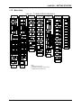
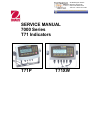
99 Washington Street
Melrose, MA 02176
Phone 781-665-1400
Toll Free 1-800-517-8431
Visit us at www.TestEquipmentDepot.com
SERVICE MANUAL
7000 Series
T71 Indicators
T71P
T71XW
SERVICE MANUAL
7000 Series T71 Indicators:
T71P & T71XW
The information contained in this manual is believed to be accurate at the time of publication, but Ohaus
Corporation assumes no liability arising from the use or misuse of this material. Reproduction of this
material is strictly prohibited.
Material in this manual is subject to change.
© Copyright 2008 Ohaus Corporation, all rights reserved.
TM Registered trademark of Ohaus Corporation.
TABLE OF CONTENTS
CHAPTER 1 GETTING STARTED
Page No.
1.1
1.2
1.3
Introduction ................................................................................................................1-1
Service Facilities........................................................................................................1-1
Tools and Test Equipment Required .........................................................................1-2
1.3.1 Special Tools and Test Equipment List ..............................................................1-2
1.3.2 Standard Tools and Test Equipment List ...........................................................1-2
1.4 T71P and T71XW: Top and Bottom Housing ............................................................1-2
1.5 Specifications.............................................................................................................1-4
1.6 Hardware Setup or Disassembly ...............................................................................1-5
1.6.1 Connecting the Scale Base’s Load Cell .............................................................1-5
1.6.2 Jumper Connections ..........................................................................................1-6
1.6.3 RS232 Interface .................................................................................................1-6
1.7 Operation ...................................................................................................................1-7
1.7.1 Power Supply .....................................................................................................1-7
1.7.2 Overview of the Controls ....................................................................................1-7
1.7.3 Overview of the Display Indicators .....................................................................1-7
1.7.4 Overview of the Control Functions .....................................................................1-8
1.7.5 Menu Setup ........................................................................................................1-9
1.7.6 Language Menu Setup .....................................................................................1-12
1.8 Calibration................................................................................................................1-13
1.8.1 Zero Calibration................................................................................................1-13
1.8.2 Span Calibration...............................................................................................1-14
1.8.3 3-point Linearity Calibration..............................................................................1-15
1.8.4 5-point Linearity Calibration..............................................................................1-16
1.8.5 Calibration Test ................................................................................................1-17
1.8.6 Geographical Adjustment Factor ......................................................................1-17
1.9 RS232 Interface Connection....................................................................................1-18
1.9.1 Setting Communications Parameters ...............................................................1-18
1.9.2 Interface Commands ........................................................................................1-19
1.9.3 Output Format ..................................................................................................1-20
1.10 Legal For Trade (LFT) .............................................................................................1-21
CHAPTER 2 TROUBLESHOOTING
2.1
2.2
2.3
Introduction ................................................................................................................2-1
Visual Inspection........................................................................................................2-1
Diagnostic Guide .......................................................................................................2-2
2.2.1 Diagnosis............................................................................................................2-2
CHAPTER 3 MAINTENANCE PROCEDURES
3.1
Preventive Maintenance ............................................................................................3-1
3.1.1 Preventive Maintenance Checklist .....................................................................3-1
3.2 Replacement of Major Components ..........................................................................3-1
3.2.1 Main Printed Circuit Board (PCB) Replacement.................................................3-2
3.2.1 Display Printed Circuit Board (PCB) Replacement.............................................3-3
3.2.3 Membrane Switch Replacement.........................................................................3-4
CHAPTER 4 TESTING
4.1.
4.2
4.3
Testing .......................................................................................................................4-1
Power Test.................................................................................................................4-1
Performance Tests Using a Scale Base ....................................................................4-1
TABLE OF CONTENTS
CHAPTER 4 TESTING (continued)
Page No.
4.3.1 Increasing/Decreasing Load Test.......................................................................4-2
4.3.2 Overload/Underload Test ...................................................................................4-2
4.4 Performance Tests Using a Load Cell Simulator.......................................................4-3
4.5 Calibration Retention Test .........................................................................................4-3
4.6 RS232 Interface Test................................................................................................. 4.3
4.7 Print Test ...................................................................................................................4-3
CHAPTER 5 PARTS LISTS & DIAGRAMS
5-1
5-2
7000 Series T71P Indicator: Housing & Internal Parts ..............................................5-2
7000 Series T71XW Indicator: Housing & Internal Parts...........................................5-4
APPENDIX A SETUP & CALIBRATION VALUES
Appendix A. Geographical Adjustment Values .................................................................. A-1
LIST OF TABLES
TABLE NO.
1-1
1-2
1-3
1-4
1-5
1-6
2-1
4-1
5-1
5-2
A-1
TITLE
Page No.
Specifications ........................................................................................................1-3
Functions of Display Controls................................................................................1-7
Functions of Display Keypad.................................................................................1-8
T71 Menu Structure ..............................................................................................1-9
Interface Command Table...................................................................................1-18
Default Serial Output Format...............................................................................1-19
Diagnostic Guide ...................................................................................................2-3
Increasing/Decreasing Load Test..........................................................................4-2
T71P Indicator: Housing & Internal Parts ..............................................................5-3
T71XW Indicator: Housing & Internal Parts...........................................................5-5
Geographical Adjustment Values ......................................................................... A-1
LIST OF ILLUSTRATIONS
FIGURE NO.
1-1
1-2
1-3
1-4
1-5
1-6
1-7
1-8
1-9
1-10
1-11
1-12
1-13
1-14
1-15
2-1
5-1
5-1
TITLE
Top and Bottom Housing, and Rear Panel, T71P .................................................1-2
Top and Bottom Housing, and Rear Panel, T71XW..............................................1-3
Printed Circuit Board (PCB), T71 Indicator ...........................................................1-5
Load Cell Terminal Blocks J4 (Scale 1) and J7 (Scale 2) .....................................1-5
Load Cell wiring.....................................................................................................1-6
Open/shorted jumpers...........................................................................................1-6
RS232 Pins ...........................................................................................................1-6
Battery charge symbol...........................................................................................1-7
T71 Display ...........................................................................................................1-7
T71 Display Indicator.............................................................................................1-7
Changing the menu language .............................................................................1-12
T71P Wire Seal ...................................................................................................1-16
T71P Paper Seal .................................................................................................1-16
T71XW Wire Seal................................................................................................1-16
T71XW Paper Seal..............................................................................................1-16
Visual Checking Procedures .................................................................................2-1
Series 7000 T71P Indicator: Housing & Internal Parts..........................................5-2
Series 7000 T71XW Indicator: Housing & Internal Parts ......................................5-4
CHAPTER 1 GETTING STARTED
1.1
INTRODUCTION
This service manual contains the information needed to perform routine maintenance and
service on the Ohaus T71 Indicators. The contents of this manual are contained in five
chapters:
Chapter 1 Getting Started – Contains information regarding service facilities, tools and test
equipment, specifications, hardware setup or disassembly, operating the Indicator, scale setup
and calibration, and configuring the Indicator’s communication and Legal-for-Trade menus.
Chapter 2 Troubleshooting – Contains a diagnosis/diagnostics chart and error code table.
Chapter 3 Maintenance Procedures – Contains preventive maintenance procedures and
disassembly, repair and replacement procedures.
Chapter 4 Testing – Contains an operational test, segment display test, performance tests and
adjustments.
Chapter 5 Drawings and Parts Lists – Contains exploded views of T71 Indicators, identifying
all serviceable components.
Before servicing the indicator, you should be familiar with the Instruction Manual which is
packed with every indicator.
1.2
SERVICE FACILITIES
To service an indicator, the service area should meet the following requirements:
•
Must be protected from electrostatic discharge.
•
Should be temperature controlled and meet the indicator specifications for temperature
environmental requirements. See specifications for temperature range.
•
Must be free of vibrations such as fork lift trucks close by, large motors, etc.
•
Must be free of air currents or drafts from air conditioning/heating ducts, openwindows,
people walking by, fans, etc.
•
Area must be clean and air must not contain excessive dust particles.
•
Work surface must be stable and level.
•
Work surface must not be exposed to direct sunlight or radiating heat sources.
CHAPTER 1 GETTING STARTED
1.3
TOOLS AND TEST EQUIPMENT REQUIRED
In order to properly service the Indicator, certain special tools and test items are required in
addition to standard electronic tool kits. These items are listed as follows:
1.3.1 Special Tools and Test Equipment List
1. Ohaus Scale Base.
2. Load Cell Simulator optional.
3. Computer with RS232 Interface.
4. RS232 Interface cable.
5. Data Printer for use with RS232 communications.
6. ESD work station or mat.
1.3.2 Standard Tools and Test Equipment List
1. Standard Electronics Tool Kit
2. Digital Voltmeter (DVM), with clip-on probes. Input impedance of at least 10 megohms in
the 1 Volt dc position.
3. Soldering Iron, solder and flux remover.
1.4
Top and Bottom Housing
Adjusting
Knobs
Mounting
Bracket
Security screw
4 screws
Battery
Compartment
Power
Receptacle
Hole plug
for option
Scale 1 Load Cell
Cable Gland
RS232
Connector
Load Cell Connector for Scale 1
Scale 2 Load Cell Cable Gland
Figure 1-1. Top and Bottom Housing, and Rear Panel, T71P.
CHAPTER 1 GETTING STARTED
1.4
Top and Bottom Housing
Adjusting
Knobs
Mounting
Bracket
4 hex-head
bolts
Relay Option Cable
RS232,
Scale 2
RS485/422
Scale 1
Load Cell
Cables
RS232 Cable
Security screw
Power Cord
Figure 1-2. Top and Bottom Housing, and Rear Panel, T71XW.
CHAPTER 1 GETTING STARTED
1.5
SPECIFICATIONS
TABLE 1-1. SPECIFICATIONS
Model
T71P
T71XW
Maximum Displayed
Resolution
1:50,000
Maximum Approved Resolution
1:10,000
Maximum Counting Resolution
1:500,000
Weighing Units
Kg, lb, g, oz, lb:oz, tonnes, custom
Static Weighing, Dynamic Weighing, Parts Counting,
Checkweighing, Percent Weighing, Vehicle Weighing
Functions
Display
25 mm / 1 in High, 2-line LCD
Over/Accept/Under Indicators
Red, Green, Yellow LED
Backlight
White LED
Ingress Protection
---
IP66
Load Cell Excitation Voltage
5V DC
Load Cell Drive
Up to 8 x 350 ohm load cells
Load Cell Input Sensitivity
Up to 3mV/V
Stabilization Time
Within 2 seconds
Auto-Zero Tracking
Off, 0.5, 1 or 3 divisions
Zeroing Range
2% or 100% of capacity
Span Calibration
1 kg or 1 lb to 100% capacity
RS232, External Input; optional Com2*
Interfaces
Overall Dimensions
(W x D x H) (in/mm)
Net Weight (lb/kg)
Shipping Weight (lb/kg)
Operating Temperature Range
10.2 x 2.7 x 6.6 /
260 x 71 x 168
10.3 x 3.0 x 5.8 /
262 x 76 x 149
3.3 / 1.5
7.7 / 3.5
5 / 2.3
9.5 / 4.3
–10°C to 40°C / /14°F to 104°F
Main Power
100-240 VAC / 50-60 Hz, Internal Universal Power Supply
Battery Power
6 C-type (LR14) Batteries
Rechargeable battery pack
(option)
*Can be either RS232 or RS422/485.
Rechargeable battery pack
(option)
CHAPTER 1 GETTING STARTED
1.6
HARDWARE SETUP OR DISASSEMBLY
Both the T71P and T71XW connect to a scale base through a Load Cell Cable that connects to
the Indicator’s Main Printed Circuit Board (PCB).
CAUTION:
ELECTRICAL SHOCK HAZARD. REMOVE ALL POWER CONNECTIONS TO THE
INDICATOR BEFORE SERVICING OR MAKING INTERNAL CONNECTIONS.
The process of opening the Housing varies slightly for each model:
T71P:
1. Remove the four Phillips head screws
from the rear housing.
T71XW:
1. Remove the four hex head screws from
the rear housing.
2. Open the housing; disconnect the
ribbon cable from the top of the PCB.
2. Open the housing by carefully pulling
the top of the front housing forward.
Figure 1-2 shows T71’s Main PCB, with connectors, jumpers, terminals and switches indicated.
Power Supply
connector
Real Time
Clock Battery
Scale 1 Load Cell
Terminal Block J4
Scale 1 Sense
Jumper W2
Scale 2 Sense
Jumper W3
Scale 2 Load
Cell Terminal
Block J7
COM2 Connector
J8 (Optional:
RS232 or
RS422/485)
Scale 2 Sense
Jumper W4
Battery
connector
(T71P only)
Rechargeable
Battery
Connection J3
(T71P opposite side)
Security Switch
SW1
Scale 1 Sense
Jumper W1
Alibi Option
PCB Connection
Scale 1 Load Cell
Connector J14
(T71P only)
External Input
Terminal Block J9
RS232 Terminal J7
(T71XW only)
RS232 Connector
(T71P only)
Figure 1-3. Printed Circuit Board (PCB), T71 Indicator.
1.6.1
Connecting the Scale Base’s Load Cell
The T71P has a circular connector jack on its Bottom Housing. The white plastic six-wire plug
connects to the Scale 1 Load Cell Connector J14. (See Figure 1-3.)
Attach a base without a circular connector to one of the Load Cell Terminal Blocks on the Main
PCB. Pass the load cell cable through a Cable Gland (see Figure 1-1) and attach it to Terminal
Block J4 or Terminal Block J7. (See Figure 1-4.) Tighten the Cable Gland to secure the cable
and maintain a tight seal. Jumper connections must be shorted or opened as follows:
Figure 1-4. Load Cell Terminal Blocks J4 (Scale 1) and J7 (Scale 2).
CHAPTER 1 GETTING STARTED
1.6.2
Jumper Connections
When a 4-wire load cell is attached to terminal block J4, jumpers W1 and W2 must be shorted.
When a 6-wire load cell is attached to terminal block J4, jumpers W1 and W2 must be open.
When a 4-wire load cell is attached to terminal block J7, jumpers W3 and W4 must be shorted.
When a 6-wire load cell is attached to terminal block J7, jumpers W3 and W4 must be removed.
+EXC
+SIG -SIG -EXC
+SENS GND -SENS
Figure 1-5. Load Cell wiring.
1.6.3
Pin
1
2
3
4
5
6
7
Connection
+Excitation
+Sense
+Signal
GND
–Signal
–Sense
–Excitation
Figure 1-6. Open/shorted jumpers.
RS232 Interface
The T71P has a built-in RS232 Interface: a standard 9-pin D-style female connector on the back
of the T71P Housing. In addition, each model (T71P and T71XW), has an optional COM2
connector, which can be either RS232 or RS422/485. The optional interface is available
separately, with its own instructional manual for installation and configuration.
The RS232 pin configuration for the T71P is illustrated in Figure 1-7, below.
4
5
9
2
3
8
7
1
6
Figure 1-7. RS232 Pins.
Pin
1
2
3
4
5
6
7
8
9
Connection
N/C
TXD
RXD
N/C
GND
N/C
CTS
RTS
N/C
For software setup of the RS232 Interface, through the Indicator’s menu, see Section 1.9.
All other aspects of hardware configuration and setup are described in the Instruction Manual.
CHAPTER 1 GETTING STARTED
1.7
OPERATION
This section contains information on the basic operation of the Indicator. An exploded view
drawing is included in Chapter 5 which identifies all components of the indicator. The
descriptions in this manual refer to the names of the components identified in the exploded view
drawing with the numbered callout.
1.7.1
Power Supply
Both models have an Internal Universal Power Supply, 100-240 VAC / 50-60 Hz. For the
T71XW, connect the power cord to a properly grounded electrical outlet. For the T71P, connect
the AC power cord to the power receptacle on the rear of the Bottom Housing, then connect the
AC plug to an electrical outlet.
The T71P indicator can also be operated on six alkaline
batteries (not supplied) when AC power is not available.
It will automatically switch to battery operation if there is power
failure or the power cord is removed. The indicator can
operate for up to 80 hours on battery power.
0 % - 5 % charged
5 % - 25 % charged
26 % - 50 % charged
51 % - 75 % charged
During battery operation, the battery charge symbol indicates
the battery status. The indicator will automatically turn-off
when the batteries are fully discharged.
1.7.2
OVERVIEW OF THE CONTROLS
76 % - 100 % charged
Figure 1-8. Battery charge
symbol.
Capacity label
window
Under, Accept &
Over LEDs
Keypad
7-segment, 6-digit
LED display
Control Buttons
Figure 1-9. T71 Display.
1.7.3
OVERVIEW OF THE DISPLAY INDICATORS
Scale symbol
Net symbol
Range symbol
Center of Zero
indicator
Kilogram, Gram,
Percent, Pound, Ounce,
Pound:Ounce, Tonne,
Pieces symbols
Negative symbol
Stable weight
indicator
Preset Tare, Tare,
Brutto, Gross,
Memory symbols
14-segment
display
Figure 1-10. T71 Display Indicator.
Dynamic
symbol
Battery charge
symbol
CHAPTER 1 GETTING STARTED
1.7.4
OVERVIEW OF THE CONTROL FUNCTIONS
TABLE 1-2. FUNCTIONS OF DISPLAY CONTROLS
Button
Primary
Function
(Short
Press)
ON/ZERO
Turns the
Indicator on
If Indicator is
on, sets zero.
Secondary
Function
(Long
Press)
Off
Turns the
Indicator off.
PRINT
FUNCTION
Sends the
Initiates an
current value to application mode.
the COM port if
Temporarily
AUTOPRINT is
displays the
set to Off.
active mode’s
reference data.
TARE
Performs a tare
operation.
LIBRARY
Display the library
data.
Mode
Allows changing
the application
mode.
Press and hold
allows scrolling
through modes.
Menu
Enter the User
menu.
Edit
Enable editing
the current library
record.
Menu
Function
(Short
Press)
No
Back
Yes
Accepts the
Advances to the
Moves back
current menu or next menu or to previous menu
setting.
menu item.
item.
Rejects the
Decrements the
current setting
value.
on the display
and advances to
the next
available
setting.
Increments the
value.
Exit
Exits the User
menu.
Aborts a
calibration in
progress.
Library
Function
(Short
Press)
No
Back
Yes
Accepts the
Advances to the
Moves back
current setting.
next library or to previous library
setting.
or setting.
Increments the Decrements the
displayed value. displayed value.
Exit
Exits the library.
Units
Changes the
weighing unit.
CHAPTER 1 GETTING STARTED
1.7.4
OVERVIEW OF THE CONTROL FUNCTIONS
TABLE 1-3. FUNCTIONS OF DISPLAY KEYPAD
Button
Primary
Function
(Short
Press)
1
2ABC through 9WXYZ
Enter 1 on Enter alphanumeric values on the
the display. display using the multi-tap text entry
method.
Secondary
1s2
Function Change
(Long
display
Press)
between
Scale 1 and
Scale 2.
1.7.5
._0
Enter
Enter 0 on
decimal
the display.
point,
space or
dash on the
display.
Info
Show the
Accumulation
statistics on
the display.
CLR
Clear the
last
character
from the
display
+/Change the
polarity of
the
displayed
value.
Menu Setup
To enter the Menu Mode, press and hold the TARE/Menu button until MENU appears on the
display. The first upper level menu appears on the display.
Use Yes, No, Back, and Exit to navigate in Menu Mode:
– Yes Allows entry into the displayed menu.
Accepts the displayed setting and advances to the next menu item.
– No Skips by the displayed menu.
Rejects the displayed setting or menu item and advances to the next available item.
– Back Moves backwards through the upper and middle level menus.
Backs out of a list of selectable items to the previous middle level menu.
– Exit Exits from menu directly to the active weighing mode.
CHAPTER 1 GETTING STARTED
1.7.5
Menu Setup
Table 1-4. T71 MENU STRUCTURE (Part 1).
CAL
SETUP
ZERO1
RESET
READOUT
YES
(1)
RESET
NO
ON
DUAL
SCALE
OFF
STABLE
RANGE
(2)
0.5d
1d
…
5d
AVG
LEVEL
LOW
MED
HIGH
UNIT
YES
YES
RESET
NO
ZERO2
MODE
RESET
NO
KILOGRAMS
(2)
ON
WEIGH
SPAN1
(2)
DUAL
..
.
.1cap
RANGE2
SINGLE
(2)(3)
DUAL
AZT
(2)
POUNDS
(2)
COUNT
GRAMS
(2)
APW
OPTIMIZE
OFF
0.5d
1d
3d
BACK
LIGHT
SELECT CAP
AND UNIT
CAPACITY2
(2)(3)
(1)
AUTO
SELECT CAP
AND UNIT
SHUT
OFF
GRAD1 (2)
LINEARITY2
SELECT GRAD
(1)(3)
ON
OUNCES
(2)
ON
AUTO
CHECK
WEIGH
ON
MANUAL
SEMI
AUTO
OFF
OFF
SET 1
SET 2
SET 5
LEVEL
(SECONDS)
CUSTOM
(2)
0
...
60
N
OFF
CAL TEST2
(3)
N
END
CAL
ON
00
...
12
…
31
POWER
ON
UNIT
(2)
ZERO
RANGE
(2)
2%
100%
AUTO
TARE
(2)
Y
N
END
MODE
Y
N
Y
OFF
ON
ACCEPT
ACCUMULATE
(2)
RETAIN
ZERO
(2)
OFF
ON
Notes:
(1) Hidden when LFT is ON.
(2) Locked at current setting when LFT is ON.
(3) Hidden when Dual Scale is OFF.
OFF
ON
OFF
LFT
ON
BEEPER
VOLUME
OFF
LO
HI
OFF
BEEPER ACCEPT
SIGNAL UNDER
OVER
UND-OVR
KEY
BEEP
ON
OFF
ON
LIBRARY
OFF
ON
ALIBI
OFF
N
END
READOUT
END
SETUP
Y
SET
.....
type
TYPE
12
24
set
SET
.....
set
OFF
ON
TIME
OFF
ON
OFF
ON
USER
ID
SET
PROJ
ID
SET
SCALE
ID
SET
OFF
ON
OFF
ON
OFF
SET FACTOR,
EXP & LSD
ON
VEHICLE
AUTO
kg
g
lb
oz
lb:oz
t
c
MDY
DMY
YMD
OFF
TONNES
(2)
5 SEC
...
30
SEC
SELECT GRAD
CAL TEST1
POUNDS:
OUNCES
(2)
OFF
ON
OFF
GROSS
Gross
INDICATOR Brutto
GRAD2 (2)(3)
TYPE
type
OFF
OFF
(2)
LINEARITY1
(1)
OFF
PERCENT
CAPACITY1
..
.
.1cap
GEO
NO
ON
OFF
full cap
(1)(3)
YES
RESET
NO
DATE
ON
full cap
(1)
SPAN2
SINGLE
YES
OFF
(1)(3)
RANGE1
GMP
END
UNIT
Y
N
END
GMP
Y
CHAPTER 1 GETTING STARTED
1.7.5
Menu Setup
Table 1-4. T71 MENU STRUCTURE (Part 2).
PRINT-1
YES
OFF
NO
STABLE
ONLY (2)
ON
RESET
OFF
On Stable
1S..
1M..
.
.
1H
Interval
Continuous
Accept
PARITY
Off/On
Net
Off/On
Header
Off/On
Off/On
Project ID
Off/On
Scale ID
Off/On
Difference
Date&Time
Content
Gross
Tare
Off/On
Header
Off/On
User ID
Off/On
Project ID
Off/On
Scale ID
Off/On
Off/On
Difference
Off/On
Off/On
Date&Time
Off/On
Info
Off/On
Info
Off/On
App Mode
Off/On
App Mode
Off/On
Name
Off/On
Name
Off/On
Format
Multiple
Single
Feed
Line Feed
4 Line Feed
Form Feed
Format
Multiple
Single
Feed
Line Feed
4 Line Feed
Form Feed
NO
7EVEN
7ODD
7NoP
8NoP
PARITY
Off
Tare
Zero
Print
Funct
Start-Stop
Tare-S-S
EXT
INPUT
1
STOP
2
NONE
XONXOFF
HARDWARE
ADDRESS
PRINT
ALT
COMMAND TARE
ZERO
LOCK
ALL
END
PRNT-2
ON
OFF
OFF
ON
ON
OFF
SETUP
ZERO
ON
OFF
OFF
OFF
ON
PRINT
ON
ON
OFF
1
OFF
MODE
Type
Relay Sequence
Output Contact
2
UNIT
ON
ON
OFF
OFF
FUNCTION
UNIT
OFF
01
…
99
ON
ON
Stable
OFF
ON
OFF
MODE
OFF
ON
NONE
XONXOFF
ON
Simultaneous
b-b-M
OFF
TARE
ON
OFF
M-b-b
OFF
ON
PRINT
ALT
TARE
COMMAND
ZERO
END COM1
ON
OFF
Hold
COM1
ON
N
ENTER “OFF” OR
ALPHANUMERIC
ENTRY
Y
MENU
Normal
Type
OFF
Open
COM2
ON
Closed
OFF
GMP
END COM2
Y
ON
END I/O
N
Y
OFF
I/O
ON
N
Y
OFF
OFF
READOUT
YES
N
NO
PRINT-2
ENTER “OFF” OR
ALPHANUMERIC
ENTRY
N
YES
ON
7EVEN
7ODD
7NoP
8NoP
LIST
Y
RESET
NO
CALIBRATE
300
….
9600
….
19200
NO
YES
END
PRNT-1
BAUD
N
Layout
Content
Off/On
Off/On
LIST
N
Off/On/Num
Result
Net
User ID
YES
NO
Stable
Load&Zero
Gross
Off/On
RESET
YES
PRINT-1
Off/On/Num
Tare
300
….
9600
….
19200
Load
HandSh
Load&Zero
Result
Layout
On
Stable
On
Stable
STOP
Load
NO
Input
Beep
1S..
1M..
.
.
1H
INTER
RESET
Contact
INTER
NO
YES
OFF
ON
OFF
On Stable
AUTO
PRINT
Interval
Continuous
Accept
RESET
LOCK KEY
LOCK MENU
OFF
BAUD
AUTO
PRINT
YES
Sequence
STABLE
ONLY (2)
I/O
YES
RESET
NO
COM2
HandSh
RESET
COM1
PRINT-2
Notes:
(1) Hidden when LFT is ON.
(2) Locked at current setting when LFT is ON.
(3) Hidden when Dual Scale is OFF.
END
LOCK MENU
Y
END
LOCK KEY
Y
CHAPTER 1 GETTING STARTED
1.7.6
Language Menu Setup
The T71 menus are available in English, Spanish, German, French and Italian. To change the
menu language, press and hold TARE/Menu until MENU appears. When the button is
released, the Legal For Trade status is displayed, followed by the first menu.
To navigate the menus, press No to move to the next menu or Back to move to the previous
one. Press Yes to enter the displayed menu. Press Exit to immediately leave a menu and
return to weighing mode.
The map below shows the steps to enter the Language menu and choose Español.
0.000
kg
Menu
mMENU
CALIBRATION
No
No
mMENU
SETUP
mMENU
mMENU
READOUT
MODE
Yes
CAL
ZERO
SEtUP
DUAL SCALE
rEAd
rEAd
STABLE RANGE
LANGUAGE
Yes
No
LANG
ENGLISH
LANG
ESPANOL
Exit
0.000
Figure 1-11. Changing the menu language.
kg
CHAPTER 1 GETTING STARTED
1.8
CALIBRATION
Four calibration processes are available: Zero, Span, 3-point Linearity and 5-point Linearity
Calibration. In addition, a Calibration Test and Geographical Adjustment Factor setting are
accessible from the CAL menu.
Preliminary Steps:
1. Be sure appropriate calibration masses are available before beginning calibration.
2. Be sure the scale base is level and stable during the entire calibration process.
3. If LFT is set to On, calibration is unavailable.
To set LFT to OFF, see Section 1.10, page 1-19.
Note: To use the LFT mode again after turning it off, it is necessary to have the
Indicator locked and sealed by local Weights and Measures authorities.
4. If the Calibration Menu is locked in the Menu Lock submenu, turn it back on:
– Press and hold TARE/Menu until MENU LFT OFF appears briefly, followed by MENU
CALIBRATION. Press No until MENU MENU LOCK appears. Press Yes.
– L.MENU RESET appears. Press No. L.MENU LOCK CAL appears. Press Yes.
– L.CAL OFF flashes. Press Yes. Then Press Exit to return to weighing mode.
– Open the Indicator and put the Security Switch on the Main PCB in the OFF position.
5. Allow the Indicator to warm up for approximately five minutes after stabilizing to room
temperature.
6. To abort calibration, press the Exit button anytime during the calibration process.
1.8.1
Zero Calibration
Zero calibration uses one calibration point. The zero calibration point is established with no
weight on the scale. Use this calibration method to adjust for a different pre-load without
affecting the span or linearity calibration.
Press and hold TARE/Menu until LFT OFF flashes and CALIBRATION appears.
Press Yes. CAL ZERO appears. Press Yes.
Note:
If DUAL SCALE is OFF, the ZERO, SPAN, 3PTLIN, 5PTLIN menu items are displayed.
If DUAL SCALE is ON, the ZERO1, ZERO2, SPAN1, SPAN2, 3PTLIN1, 3PTLIN2,
5PTLIN1, 5PTLIN2 menu items are displayed.
With no load on the scale, press Yes to set the new zero point.
ZErO
O
The display shows ZERO --C--, then ZERO DONE and returns to the
current application mode.
ZErO
lb
--C--
ZErO
lb
DONE
0.000
lb
CHAPTER 1 GETTING STARTED
1.8.2
Span Calibration
Use this calibration method to adjust the zero calibration point and span calibration point,
without affecting the linearity calibration. Be sure there is no load on the scale.
Press and hold TARE/Menu until LFT OFF flashes and CALIBRATION
appears. Press Yes. CAL ZERO appears. Press No.
CAL SPAN appears. Press Yes. SPAN and the current unit of measure
and Span calibration point flash.
SPAN
kg
Note: To change the span calibration point, press No and enter the
value using the keypad. Then press Yes.
To change the calibration unit of measure, press No to alternate
between kg and lb.
SPAN
kg
SPAN
lb
Place the specified calibration weight on the scale and press Yes.
The display shows SPAN --C--, followed by SPAN DONE.
SPAN
lb
SPAN 0 appears. With no load on the scale, press Yes.
SPAN
lb
SPAN
lb
SPAN
lb
10
5
5
--C--
0
The display shows SPAN --C--, followed by SPAN DONE, and returns to
the current application mode.
--C--
DONE
0.000
lb
CHAPTER 1 GETTING STARTED
1.8.3
3-point Linearity Calibration
This calibration method uses three points. The full-calibration point is established with a weight
on the scale. The mid-calibration point is established with a weight equal to half of the full
calibration weight on the scale. The zero calibration point is established with no weight on the
scale. The mid-calibration points cannot be altered by the user during the calibration procedure.
Press and hold TARE/Menu until LFT OFF flashes and CALIBRATION
appears. Press Yes. CAL ZERO appears. Press No.
CAL SPAN appears. Press No. 3 PT LINEAR appears.
CAL
With no load on the scale, press Yes. The display shows the current full
load calibration point and calibration unit of measure.
3LIN
kg
Note: To change the full load calibration point, press No and enter the
desired value using the keypad. Then press Yes.
To change the calibration unit of measure, press No to alternate
between kg and lb.
3LIN
kg
3LIN
lb
3LIN
lb
3LIN
lb
3LIN
lb
3LIN
lb
3LIN
lb
3LIN
lb
3 PT LINEAR
10
5
5
Place the specified full load calibration weight on the scale and press
Yes. The display shows --C--, followed by the 1/2 load calibration point.
--C--
2.5
Place the specified 1/2 load calibration weight on the scale and press
Yes. The display shows --C--, followed by the zero calibration point.
--C--
0
With no load on the scale, press Yes. The display shows --C--, then
DONE, and returns to the current application mode.
--C--
DONE
0.000
lb
CHAPTER 1 GETTING STARTED
1.8.4
5-point Linearity Calibration
Use this calibration method to adjust the zero calibration point, 1/4, 1/2.
3/4 and full load calibration points. Go to the Calibration menu, and
Press No until 5 PT LINEAR appears.
CAL
With no load on the scale, press Yes. The display shows the current full
load calibration point and calibration unit of measure.
5LIN
kg
Note: To change the full load calibration point, press No and enter the
desired value using the keypad. Then press Yes.
To change the calibration unit of measure, press No to alternate
between kg and lb.
5LIN
kg
5LIN
lb
5LIN
lb
5LIN
lb
5LIN
lb
5LIN
lb
5LIN
lb
5LIN
lb
5LIN
lb
5LIN
lb
5 PT LINEAR
15
10
10
Place the specified full load calibration weight on the scale and press
Yes. The display shows --C--, followed by the 3/4 load calibration point.
--C--
7.5
Place the specified 3/4 load calibration weight on the scale and press
Yes. The display shows --C--, followed by the 1/2 load calibration point.
--C--
5
Place the specified 1/2 load calibration weight on the scale and press
Yes. The display shows --C--, followed by the 1/4 load calibration point.
--C--
2.5
Place the specified 1/4 load calibration weight on the scale and press
Yes. The display shows --C--, followed by the zero calibration point.
--C--
0
With no load on the scale, press Yes. The display shows --C--, then
DONE, and returns to the current application mode.
5LIN
lb
--C--
5LIN
lb
DONE
0.000
lb
CHAPTER 1 GETTING STARTED
1.8.5
Calibration Test
NOTE: Calibration Test is always available (even when LFT is set to ON).
CAL
CAL TEST
Calibration test is used to compare a known calibration weight against the stored span
calibration data. Go to the Calibration menu, and Press No until CAL CAL TEST appears.
With no load on the scale, press Yes. The display shows the zero load
calibration point.
tESt
With no load on the scale, press Yes. The display shows --T--, followed
by the full load calibration point.
tESt
kg
0
kg
--T--
tESt
kg
tESt
kg
10
Place the specified full load calibration weight on the scale and
press Yes. The display shows --T--, followed by difference between
the calibration weight and the stored calibration data.
--T--
0.001
kg
10.000
kg
DIFFERENCE
After five seconds, the display returns to the current application mode.
1.8.5
Geographical Adjustment Factor
The Geographical Adjustment Factor (GEO) is used to compensate for variations in gravity.
To determine the GEO factor that corresponds to your location, see Appendix A.
Note: Changing the GEO Factor alters the calibration. The GEO value was set at the factory
and should only be changed if the location of use varies from the default setting.
To adjust the GEO Factor, go to the Calibration menu, and Press No until CAL GEO appears.
Press Yes. The default GEO setting appears. Press No to increment the number, or Back to
decrement, until the desired number appears. Then press Yes.
Settings from 1 to 31 are available.
CAL GEO appears again. Press No to exit the GEO menu. Then press Exit to return to the
current application mode.
CHAPTER 1 GETTING STARTED
1.9
RS232 INTERFACE CONNECTION
The T71 has a bi-directional RS232 interface for communication with printers and computers.
When the Indicator is connected to a printer or Programmable Logic Controller (PLC), displayed
data can be output various ways, depending on PRINT menu settings.
For hardware setup of the RS232 Interface, see Section 1.5.2, page 1-6.
1.9.1
Setting Communications Parameters (COM1)
Note: Only the COM1 menu appears unless the COM2 interface is set up.
The T71 Indicator’s default communication parameters are baud rate 9600 bits per second
(bps), 8 databits, no parity, Handshake XON/XOFF, Address Off, Alt Command (for Print) Off,
Alt Tare Off, and Alt Zero Off.
To change these settings use the COM1 menu, as follows:
1. Press and hold TARE/Menu until LFT OFF flashes and CALIBRATION
appears. Press No until COM1 appears. Press Yes. RESEt appears. Press No
(unless you want to restore the factory defaults).
2. COM 1 bAUd appears. Press Yes.
COmM 1
BAUD
3. The default Baud rate setting, 9600 bps, appears. To change the setting, press No.
The menu cycles to the next setting each time you press No: first 9600, then 300, 600,
1200, 2400, 4800, and 9600 again. Press Yes when the desired setting appears.
COM 1 bAUd appears again. Press No.
4. COM 1 PAritY appears. Press Yes. The default Parity setting,
8 NONE, appears. To change the setting, press No.
The menu cycles to the next setting each time you press No:
first 7 Even, then 7 Odd, 7 None, and 8 None again. Press Yes
to accept a setting. PAritY appears again. Press No.
5. COM 1 StOP BIT appears. Press Yes. The default Stop Bit
setting, 1, appears. To change the setting, press No.
The menu toggles to the next setting each time you press No:
first 1, then 2, then 1 again. Press Yes when the desired setting
appears. COM 1 StOP BIT appears again. Press No.
COmM 1
PARITY
COmM 1
STOP BIT
6. COM 1 HANdSHAKE appears. Press Yes. The default setting,
NONE, appears. To change the setting, press No.
The menu toggles to the next setting each time you press No:
first XON-XOFF, then HARDWARE, then NONE again. Press
Yes to accept a setting. Then menu moves to the next item.
COmM 1
7. COM 1 ALT COMMAND appears. Press Yes to set a different
command character for the P (Print), T (Tare) and Z (Zero)
commands. Otherwise, press No. Then press Yes when
COM 1 END COM1 appears.
COmM 1
HANDSHAKE
ALT COMMAND
At this point, if a second communication interface is present, the COM2 menu is available.
Otherwise, press Exit to return to current application mode.
CHAPTER 1 GETTING STARTED
1.9.2
Interface Commands
The RS232 Interface enables a computer to be used to control some functions of the Indicator
using the commands listed in Table 1-4.
TABLE 1-5. SERIAL INTERFACE COMMAND TABLE.
Command
1
Function
ON
Turns the indicator on.
OFF
Turns the indicator off.
IP
2
Immediate Print of displayed weight (stable or unstable).
P
Print stable displayed weight (according to stability setting).
CP
Continuous Print
SP
Print when stable.
xP
Interval Print x = Print Interval (1-3600 sec)
Z2
Same as pressing Zero button
2
Same as pressing Tare button
T
xT
Download Tare value in grams (positive values only). Sending 0T clears tare
(if allowed)
PU
Print current unit: g, kg, lb, oz, lb:oz
xU
Set scale to unit x: 1=g, 2=kg, 3=lb, 4=oz, 5=lb:oz
PV
Version: print name, software revision and LFT ON (if LFT is set ON).
H x “text”
Esc R
Enter Header line , where x = line number 1 to 5, “text” = header text up to 24
alphanumeric characters
Global reset (All menu settings are reset to the original factory defaults.)
Notes:
1. Commands sent to the Indicator must be terminated with a carriage return (CR) or
carriage return-line feed (CRLF).
2. Alternate command characters may be defined by the user.
3. Data output by the Indicator is always terminated with a carriage return-line feed (CRLF).
CHAPTER 1 GETTING STARTED
1.9.3
Output Format
The Result Data is output in the following format.
TABLE 1-6. DEFAULT SERIAL OUTPUT FORMAT
Field:
Label1
Space2
Weight3
Space2
Unit4
Space2
Stability5
Space2
G/N6
Space
Term Characters
Length:
≤11
≤1
9
≤1
≤5
1
≤1
≤1
≤3
≤1
0 ??
Notes:
1. In certain cases, a Label field of up to 11 characters is included. –
2. Each field is followed by a single delimiting space (ASCII 32).
3. The Weight field is nine right-justified characters. If the value is negative, the “– “
character is located at the immediate left of the most significant digit.
4. The Unit field contains the unit of measure abbreviation, up to five characters.
5. The Stability field contains the “?” character if the weight reading is not stable. The
Stability field and the following Space field are omitted if the weight reading is stable.
6. The G/N field contains the net or gross indication. For net weights, the field contains
“NET”. For gross weights, the field contains nothing, “G” or “B”, depending on the
GROSS INDICATOR menu setting.
7. The Termination Characters field contains CRLF, Four CRLF or Form Feed (ASCII 12),
depending on the LINE FEED menu setting.
For more information, see the Instruction Manual.
CHAPTER 1 GETTING STARTED
1.10 LEGAL FOR TRADE (LFT)
NOTE: When LFT is set to ON through the LFT sub-menu, and the Security Switch on the Main
PCB is set to ON (see Figure 1-1, page 1-2), the following menu settings cannot be changed:
Span Calibration, Linearity Calibration, Calibration Unit, GEO, LFT, Capacity,
Graduation, Zero Range, Stable Range, AZT, Modes, and Units.
To enable editing of these menu settings, open the Indicator and put the Security Switch on the
Main PCB in the OFF position. Then set the LFT menu item to OFF, as follows:
1. Press and hold TARE/Menu until MENU LFT OFF appears briefly, followed by MENU
CALIBRATION. Press No.
2. S.E.t.U.P appears. Press Yes. Then press No until LFt appears. Press Yes.
3. OFF appears. Press Yes.
4. LFt appears again. Press No. Then press Exit to return to the current application
mode.
5. It is now possible to use the abovementioned menus.
After the Security Switch has been turned off, before it can be used in a trade approved
application, it must be inspected in accordance with local weights and measures regulations.
The weights and measures official may apply a wire or paper security seal as shown below.
Figure 1-12. T71P Wire Seal.
Figure 1-13. T71P Paper Seal.
Figure 1-15. T71XW Paper Seal
Figure 1-14. T71XW Wire Seal
CHAPTER 1 GETTING STARTED
CHAPTER 2 TROUBLESHOOTING
2.1
INTRODUCTION
This section of the manual covers visual inspection of the Indicator, troubleshooting, and a
Diagnostic Guide, Table 2-1. For setup and connection to either a known good base or
simulator, see Chapter 1. Follow all directions step by step. Make certain that the work area is
clean and use care when handling components of the Indicator.
2.2
VISUAL INSPECTION
Carefully remove the Indicator from its packing container and remove any packing material
fastened to the unit. Note all items supplied with the unit such as AC power supply, cables,
instruction manual, weights, etc. Keep a record of all items and note their condition.
1. Examine the Indicator for signs of abuse such as a cracked top cover or base, damage
from liquids, cracks on corners, which may suggest the unit was dropped.
2. Open the Indicator by removing the four screws in the rear housing. Be careful not to
stretch the cables that connect the main Printed Circuit Board (PCB) to the outlets
(RS232 and Load Cell ports) and power supply.
3. Examine the top of the main PCB for cracks or signs of corrosion.
4. If it appears that corrosion may have affected the board and you want to examine the
bottom of the PCB, remove the four screws holding it to the housing.
5. Carefully lift out the main PC board. If it is cracked or shows signs of corrosion, it
requires replacement. See Chapter 3, Maintenance Procedures, for board replacement
and testing. If the Indicator shows no sign of physical damage, continue with procedures.
See chart below for visual checking procedures.
Figure 2-1. Visual Checking Procedures.
CHAPTER 2 TROUBLESHOOTING
2.3
DIAGNOSTIC GUIDE
Table 2-1 is a Diagnostic Guide designed to help locate the problem area quickly and easily.
The probable causes are listed with the most common cause first. If the first remedy does not
fix the problem, proceed to the next remedy. Before attempting any repairs, read all chapters of
this manual to be familiar with overall operation and all components.
2.2.1
Diagnosis
1. Isolate and identify the symptom
2. Refer to Table 2-1, Diagnostic Guide and locate the symptom.
3. Follow the suggested remedies in the order they appear.
4. Perform the indicated checks, or see the appropriate section of the manual.
5. Repair or replace the defective part.
NOTE:
If more than one symptom is observed, approach one area at a time,
and remember that the symptoms may be interrelated.
If a problem arises that is not covered in this manual, contact Ohaus Corporation for further
information.
CHAPTER 2 TROUBLESHOOTING
2.2.1
Diagnosis
TABLE 2-1. DIAGNOSTIC GUIDE
Symptom
Possible Cause(s)
Remedy
Unit will not turn on
Power cord not plugged in or
properly connected.
Check power cord connections. Make
sure power cord is plugged in properly
into the power outlet.
Check power source.
Power outlet not supplying
electricity.
Battery discharged.
Replace disposable batteries
or recharge NiMH Pack.
Other failure.
Check cable connections;
replace PCB.
Battery symbol blank
Battery discharged.
Replace disposable batteries
or recharge NiMH Pack.
Cannot zero the
Scale, or will not
zero when turned on
Load on Scale exceeds
allowable limits.
Load on Scale is not stable.
Load Cell damage.
Remove load on Scale.
Poor accuracy
Improper calibration
Unstable environment
Perform calibration.
Move scale to suitable location.
Unable to calibrate
Unstable environment
Incorrect calibration mass
Lock Calibration Menu set to On.
LFT menu set to On.
Main PCB failure
Move the scale to suitable location.
Use correct calibration mass.
Set Lock Calibration Menu to Off.
Set LFT menu to Off.
Replace Main PCB.
Cannot display
weight in desired
weighing unit
Unit not set to On.
Enable unit in the Units Menu.
Problems with
Display (missing
characters, partial
display, erratic or
unstable display)
Display PCB failure
Check Display PCB Cable.
Replace Display PCB.
Replace Main PCB.
Cannot change
menu settings
Menu has been locked.
Set selected menu to Off in the Lock
Menu.
Lockout Switch on the circuit board may
need to be set to the Off position.
(See Figure 1-1.)
Does not retain
correct time
Real time clock battery failure
Replace real time clock battery.
(See Figure 1-3.)
Wait for load to become stable.
Replace Load Cell.
CHAPTER 2 TROUBLESHOOTING
Symptom
Possible Cause(s)
Remedy
Error 8.1
Weight reading exceeds Power
On Zero limit.
Remove load from scale. Recalibrate
scale.
Error 8.2
Weight reading below Power On
Zero limit.
Add load to scale.
Recalibrate scale.
Error 8.3
Weight reading exceeds
Overload limit.
Reduce load on scale.
Error 8.4
Weight reading below Underload
limit.
Add load to scale.
Recalibrate scale.
Error 8.6
Weight value exceeds six digits.
Use more appropriate unit of measure.
Reduce load on scale.
----------- displayed
Busy message. Displayed during
tare setting, zero setting, printing
If this message persists, it usually
indicates the reading is not stable.
Correct the instability.
--NO—displayed
The action is not allowed.
Do not attempt this operation.
CHAPTER 3 MAINTENANCE PROCEDURES
3.1
PREVENTIVE MAINTENANCE
Ohaus Indicators are precision instruments and should be carefully handled, stored in a clean,
dry, dust-free area, and cleaned periodically. Follow these precautionary steps:
–
When an Indicator has had chemicals or liquids spilled on it, all exterior surfaces should
be cleaned as soon as possible with warm water on a damp cloth.
–
Allow at least 10 minutes for the Indicator to stabilize after moving it from an area which
is at a different temperature than the area where it is to be operated.
3.1.1
Preventive Maintenance Checklist
The Indicator should be inspected and checked regularly, as follows:
1. Unplug the AC Adapter before cleaning.
2. For the T71P, clean the outside using a cloth dampened with a mild detergent.
3. For the T71XW, use appropriate cleaning solutions for the stainless-steel Indicator
housing and rinse with water. Dry thoroughly.
CAUTION
DO NOT USE CHEMICAL CLEANERS OR SOLVENTS OF ANY TYPE.
SOME CLEANERS ARE ABRASIVE AND MAY AFFECT THE SCALE’S FINISH.
4. Check the Power Cord for broken or damaged insulation.
5. Make a visual inspection for faulty connectors, wiring, and loose hardware.
3.2
REPLACEMENT OF MAJOR COMPONENTS
The decision to replace any component should only be made after thoroughly diagnosing the
problem. If, after the replacement of any component, the Indicator is still non functional and no
other information on the subject is available in the manual, contact Ohaus Corporation by
visiting www.ohaus.com. In the United States call Ohaus Aftermarket toll free, 800-526-0659
between 8:00 a.m. and 4:00 p.m. EST.
CHAPTER 3 MAINTENANCE PROCEDURES
3.2.1
Main Printed Circuit Board (PCB) Replacement
Repairs are not recommended on the Main PCB. Component parts of the Main PCB are not
stocked by Ohaus. Replacement is recommended rather than repairing.
1. Unplug the Indicator from the AC power source.
2. Remove the four screws from the Bottom Housing.
3. Carefully separate the Top Housing and Bottom Housing – on the T71P, disconnect
the Display PCB’s ribbon cable from the top of the Main PCB.
4. Pull all cable connectors from their plugs on the Main PCB, including (on the
T71XW), the Display PCB’s ribbon cable from the Main PCB.
5. If cable-leads are connected to the Scale 2 Load Cell Connector J7 (see Figure 1-1),
loosen the terminal block’s set-screws and remove the leads.
6. On the T71P, remove the hex screws connecting the RS232 Interface port to the
Bottom Housing, so the port will clear when the PCB is lifted out.
7. Remove the four screws from the PCB. (…and, on the T71XW, a fifth securing the
grounding cable to the PCB on the lower left.)
CAUTION
When handling the PCB, grasp it by the edges only!
Do not touch the foil side. Static discharge may damage some components.
8. Lift out the PCB.
9. Carefully re-position the replacement PCB over the screw holes in the Top Cover.
Re-insert and tighten the screws.
10. Reconnect the cables removed in Steps 4 and 5.
11. On the T71P, re-insert the hex screws connecting the RS232 Interface port to the
Bottom Housing.
12. Close the Housing and re-insert the four screws.
13. Perform calibration procedures. (See Section 1.8.)
14. Perform testing procedures. (See Chapter 4.)
CHAPTER 3 MAINTENANCE PROCEDURES
3.2.2
Display Printed Circuit Board (PCB) Replacement
Repairs are not recommended on the Display PCB. Component parts of the Display PCB are
not stocked by Ohaus. Replacement is recommended rather than repairing.
1. Separate the Top and Bottom Housing. (Follow steps 1 – 3 in Section 3.2.1.)
2. On the T71XW, remove the Main PCB. (Follow steps 4 – 8 in Section 3.2.1.)
3. Remove the four screws holding the Display PCB to the Top Housing.
4. Carefully lift out the Display PCB, to avoid stretching the fine plastic ribbon cable
connected to the Membrane Switch.
5. Gently remove the two ribbon cables – one connected to the Membrane Switch, and
the other to the Main PCB. Avoid bending the pins.
6. Connect the ribbon cables to the replacement Display PCB, and position the board
over the screw holes. Insert the screws and tighten them.
7. Carefully re-position the Main PCB over its screw holes in the Top Cover.
Re-insert and tighten the screws.
8. Reconnect the cables removed in Steps 4 and 5 of Section 3.2.1.
9. On the T71P, re-insert the hex screws connecting the RS232 Interface port to the
Bottom Housing.
10. Close the Housing and re-insert the four screws.
11. Perform calibration procedures. (See Section 1.8.)
12. Perform testing procedures. (See Chapter 4.)
CHAPTER 3 MAINTENANCE PROCEDURES
3.2.3
Membrane Switch Replacement
1. Separate the Top and Bottom Housing. (Follow steps 1 – 3 in Section 3.2.1.)
2. On the T71XW, when removing the old Membrane Switch, be sure to extract the
plastic ribbon cable that connects to the PCB’s Keypad Connector.
3. Remove the protective backing from the back of the new Membrane Switch; carefully
position it on the Top Cover, starting at the bottom of the cover. Use a rolling motion
to smooth the Membrane Switch into position.
4. Carefully re-position the Main PCB over its screw holes in the Top Cover.
Re-insert and tighten the screws.
5. Reconnect the cables removed in Steps 4 and 5 of Section 3.2.1.
6. On the T71P, re-insert the hex screws connecting the RS232 Interface port to the
Bottom Housing.
7. Close the Housing and re-insert the four screws.
8. Perform calibration procedures. (See Section 1.8.)
9. Perform testing procedures. (See Chapter 4.)
CHAPTER 4 TESTING
4.1
TESTING
Before and after servicing the Indicator, operational and performance tests should be made to
determine if it meets specifications. Turn the Indicator ON and allow it to warm up for at least
ten minutes before performing these checks. The masses used for calibration should be
ASTM Class 4 or OIML Class F2 tolerance or better.
NOTE:
Make sure the test area is free from drafts and that the base rests on a level and
vibration-free surface. The masses used for final calibration must be adjusted to
ASTM Class 4 or OIML Class F2 tolerance or better.
4.2
Power Test
The purpose of this test is to determine if the electronic circuitry of the Indicator is functioning
properly or not at all. In some cases, the AC Adapter or line cord supplied with the Indicator may
have become defective.
1. Plug the AC Adapter or line cord into a suitable power source.
2. With the Indicator connected to an appropriate power supply, press the ON/ZERO Off
button. The Indicator performs a self-test, indicates the software revision and then goes
into weighing mode.
3. If all of the displays appear normal in this test, continue with the next test. If the display
did not appear, check that the AC input is good, and that the AC adapter or line cord are
functioning properly, and repeat the test. If the display was erratic, the PC board is
defective and requires replacement.
4.3
Performance Tests Using a Scale Base
These tests are performed on the Indicator using a known good scale base and test mass.
At this point, the Indicator has been checked for full display, menu setup and calibrated.
If a Load Cell Simulator is being used, proceed to paragraph 4.4.
Select the maximum possible resolution (<1:20,000) to obtain the most accurate test results.
CHAPTER 4 TESTING
4.3.1
Overload/Underload Test
This test determines if the Indicator displays the proper indication when an underload or
overload condition exists on the scale base.
1. With the Indicator ON and no mass on the scale base, lift up on the scale base
platform and observe the display. The display should indicate Error 8.2. Release the
platform. The display should return to zero.
Note: Do not exceed Load Cell capacity when testing the Indicator.
2. Place a mass on the scale base platform which slightly exceeds the capacity of the
scale base, and observe the Indicator display. The display should indicate Error 8.1.
Remove the mass from the scale base. The display should return to zero.
4.4
Performance Tests Using a Load Cell Simulator
A simulator can be used in place of a scale base if available.
–
Connect the simulator to Terminal Block J4 (the Load Cell terminal block) on the
PCB, so that EX+, EX–, S+ and S– are matched at each end of the cable.
(See Figures 1-1 and 1-2, page 1-4.)
–
Set the Jumper connections, as explained in Section 1.6.1 and 1.6.2.
Test the Indicator as follows:
1. Set the simulator to zero. Power on the Indicator. Perform a Span Calibration, with zero
at the simulator’s zero setting, and 100% capacity at the simulator’s 2.0 milli-volt setting.
2. Following calibration, check that the Indicator’s display reading is stable at each
simulator level, up to the maximum set in the calibration. If the readings are stable, the
Indicator is functioning properly.
4.5
Calibration Retention Test
This test checks that the Indicator retains calibration after power is removed and then restored.
1. Turn the Indicator OFF and disconnect the AC Adapter or power cord.
2. Wait one minute, then reconnect the AC Adapter or power cord to the Indicator.
3. Check to insure that the Indicator retained calibration settings.
4.6
RS232 Interface Test / Print Test
The RS232 Interface performance can be monitored using an external printer or computer
connected to the Indicator.
To set up communication parameters, see Section 1.9.1.
Once the communications parameters match between the Indicator and either a computer or
printer, it is possible to test the Indicator’s print function.
–
Press the Print/Units button. Printing to an external printer or computer should occur
each time the button is pressed.
CHAPTER 5 PARTS LISTS & DIAGRAMS
This section of the manual contains exploded views for the 7000 Series T71 Indicators.
The exploded view drawings are designed to identify the parts which can be serviced on the
indicator in the field.
NOTE:
In all cases where a part is replaced, the balance must be thoroughly checked
after the replacement is made. The balance MUST meet the parameters of all
applicable specifications in this manual.
If further technical information is needed, please contact your local Ohaus distributor, or:
Ohaus Corporation, www.ohaus.com
19A Chapin Road
P.O. Box 2033
Pine Brook, NJ 07058-2033 USA
Tel: 973-377-9000
Fax: 973-593-0359
In the United States call toll free, 800-526-0659 between 8:00 a.m. and 6:00 p.m. EST.
CHAPTER 5 PARTS LISTS & DIAGRAMS
5.1
7000 SERIES T71P INDICATOR: HOUSING & INTERNAL PARTS
12
11
8
13
14
9
22
18
21
4
4
6
10
70
26
23
20
15
25
24
16
5
7
3
1
2
Figure 5-1. Series 7000 T71P Indicator: Housing & Internal Parts.
CHAPTER 5 PARTS LISTS & DIAGRAMS
5.1
7000 SERIES T71P INDICATOR: HOUSING & INTERNAL PARTS
TABLE 5-1. T71P INDICATOR: HOUSING & INTERNAL PARTS
Drawing Item
Description
1
Capacity Label Kit
2
Membrane Switch
3
Front Housing
4
Feet, Set of 4,
5
Display LCD
6
Hole Plugs
7
Display PCB
8
Battery Cover
9
NiMH Battery
10
Rear Housing
11
Knob Kit (set of 2)
12
Wall Mount Kit
13
Battery Guide
14
Cable Kit
15
PCB, Power Supply
16
Power Supply PCB Cover
18
I/O Fitting
20
Hardware Kit
21
I/O Filler Plug
22
Recharge PCB
23
RS422/485 Interface Kit (Accessory)
23
RS232 Interface Kit (Accessory)
24
Relay PCB Cover
25
AC Relay Kit (Accessory)
26
Main PCB
70
Line Cord
CHAPTER 5 PARTS LISTS & DIAGRAMS
5.2
7000 SERIES T71XW INDICATOR: HOUSING & INTERNAL PARTS
Figure 5-1. Series 7000 T71XW Indicator: Housing & Internal Parts.
CHAPTER 5 PARTS LISTS & DIAGRAMS
5.1
7000 SERIES T71XW INDICATOR: HOUSING & INTERNAL PARTS
TABLE 5-1. T71XW INDICATOR: HOUSING & INTERNAL PARTS
Drawing Item
Description
1
Capacity Label Kit
2
Membrane Switch
3
Front Housing
4
Gasket
5
Display LCD
7
Display PCB
9
NiMH Battery
10
Rear Housing
11
Knob Kit (Set of 2)
12
Wall Mount Kit
14
Cable Kit
15
PCB, Power Supply
16
Cover, Power Supply PCB
17
I/O Fitting
18
I/O Fitting
19
Cable Mounts, Internal
20
Hardware Kit
21
I/O Fitting
22
Recharge PCB
23
Accessory, RS422/485 Interface Kit
23
Accessory, RS232 Interface Kit
24
Cover, Relay PCB
25
Accessory, AC Relay Kit
26
Main PCB
70
Line Cord
CHAPTER 5 PARTS LISTS & DIAGRAMS
APPENDIX A GEOGRAPHICAL ADJUSTMENT VALUES
APPENDIX A. GEOGRAPHICAL ADJUSTMENT VALUES
TABLE A-1. GEOGRAPHICAL ADJUSTMENT VALUES.
Elevation above sea level in meters
Geographical
latitude away
from the
equator (North
or South), in
degrees and
minutes.
0°00′ - 5°46′
5°46′ - 9°52′
9°52′ - 12°44′
12°44′ - 15°06
15°06′ - 17°10′
17°10′ - 19°02′
19°02′ - 20°45′
20°45′ - 22°22′
22°22′ - 23°54′
23°54′ - 25°21′
25°21′ - 26°45′
26°45′ - 28°06′
28°06′ - 29°25′
29°25′ - 30°41′
30°41′ - 31°56′
31°56′ - 33°09′
33°09′ - 34°21′
34°21′ - 35°31′
35°31′ - 36°41′
36°41′ - 37°50′
37°50′ - 38°58′
38°58′ - 40°05′
40°05′ - 41°12′
41°12′ - 42°19′
42°19′ - 43°26′
43°26′ - 44°32′
44°32′ - 45°38′
45°38′ - 46°45′
46°45′ - 47°51′
47°51′ - 48°58′
48°58′ - 50°06′
50°06′ - 51°13′
51°13′ - 52°22′
52°22′ - 53°31′
53°31′ - 54°41′
54°41′ - 55°52′
000
325
325
650
650
975
0975
1300
1300
1625
1625
1950
1950
2275
2275
2600
2600
2925
2925
3250
3250
3575
Elevation above sea level in feet
0000
1060
1060
2130
2130
3200
3200
4260
4260
5330
5330
6400
6400
7460
7460
8530
8530
9600
09600
10660
10660
11730
05
05
06
06
07
07
08
08
09
09
10
10
11
11
12
12
13
13
14
14
15
15
16
16
17
17
18
18
19
19
20
20
21
21
22
22
04
05
05
06
06
07
07
08
08
09
09
10
10
11
11
12
12
13
13
14
14
15
15
16
16
17
17
18
18
19
19
20
20
21
21
22
04
04
05
05
06
06
07
07
08
08
09
09
10
10
11
11
12
12
13
13
14
14
15
15
16
16
17
17
18
18
19
19
20
20
21
21
03
04
04
05
05
06
06
07
07
08
08
09
09
10
10
11
11
12
12
13
13
14
14
15
15
16
16
17
17
18
18
19
19
20
20
21
03
03
04
04
05
05
06
06
07
07
08
08
09
09
10
10
11
11
12
12
13
13
14
14
15
15
16
16
17
17
18
18
19
19
20
20
02
03
03
04
04
05
05
06
06
07
07
08
08
09
09
10
10
11
11
12
12
13
13
14
14
15
15
16
16
17
17
18
18
19
19
20
02
02
03
03
04
04
05
05
06
06
07
07
08
08
09
09
10
10
11
11
12
12
13
13
14
14
15
15
16
16
17
17
18
18
19
19
01
02
02
03
03
04
04
05
05
06
06
07
07
08
08
09
09
10
10
11
11
12
12
13
13
14
14
15
15
16
16
17
17
18
18
19
01
01
02
02
03
03
04
04
05
05
06
06
07
07
08
08
09
09
10
10
11
11
12
12
13
13
14
14
15
15
16
16
17
17
18
18
00
01
01
02
02
03
03
04
04
05
05
06
06
07
07
08
08
09
09
10
10
11
11
12
12
13
13
14
14
15
15
16
16
17
17
18
00
00
01
01
02
02
03
03
04
04
05
05
06
06
07
07
08
08
09
09
10
10
11
11
12
12
13
13
14
14
15
15
16
16
17
17
APPENDIX A GEOGRAPHICAL ADJUSTMENT VALUES
TABLE A-1. GEOGRAPHICAL ADJUSTMENT VALUES.
Elevation above sea level in meters
Geographical
latitude away
from the
equator (North
or South), in
degrees and
minutes.
55°52′ - 57°04′
57°04′ - 58°17′
58°17′ - 59°32′
59°32′ - 60°49′
60°49′ - 62°09′
62°09′ - 63°30′
63°30′ - 64°55′
64°55′ - 66°24′
66°24′ - 67°57′
67°57′ - 69°35′
69°35′ - 71°21′
71°21′ - 73°16′
73°16′ - 75°24′
75°24′ - 77°52′
77°52′ - 80°56′
80°56′ - 85°45′
85°45′ - 90°00′
000
325
325
650
650
975
0975
1300
1300
1625
1625
1950
1950
2275
2275
2600
2600
2925
2925
3250
3250
3575
Elevation above sea level in feet
0000
1060
1060
2130
2130
3200
3200
4260
4260
5330
5330
6400
6400
7460
7460
8530
8530
9600
09600
10660
10660
11730
23
23
24
24
25
25
26
26
27
27
28
28
29
29
30
30
31
22
23
23
24
24
25
25
26
26
27
27
28
28
29
29
30
30
22
22
23
23
24
24
25
25
26
26
27
27
28
28
29
29
30
21
22
22
23
23
24
24
25
25
26
26
27
27
28
28
29
29
21
21
22
22
23
23
24
24
25
25
26
26
27
27
28
28
20
21
21
22
22
23
23
24
24
25
25
26
26
27
27
28
20
20
21
21
22
22
23
23
24
24
25
25
26
26
27
27
19
20
20
21
21
22
22
23
23
24
24
25
25
26
26
27
19
19
20
20
21
21
22
22
23
23
24
24
25
25
26
26
18
19
19
20
20
21
21
22
22
23
23
24
24
25
25
26
18
18
19
19
20
20
21
21
22
22
23
23
24
24
25
25
29
28
28
27
27
26
26
*80252588*
P/N 80252588 SERVICE MANUAL: 7000 SERIES T71 INDICATORS
Test Equipment Depot - 800.517.8431 - 99 Washington Street Melrose, MA 02176 - TestEquipmentDepot.com