1
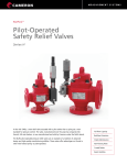
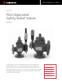
MEASUREMENT SYSTEMS
NUFLO™
Pilot-Operated
Safety Relief Valves
Series H
In the mid 1940s, a new relief valve actuated with a pilot rather than a spring set a new
standard for pressure control. The valve, manufactured over the years by companies like
Garrett, USI and Axelson, is now manufactured and sold by NuFlo Measurement Systems.
NuFlo's pilot-operated pressure relief valves are an example of a tradition of advanced design
and high-quality manufacturing abilities. These valves offer advantages not found in other
relief valves-spring- or pilot-operated.
Full Flow Capacity
Backflow Protection
Simple Maintenance
Non-Flowing Pilots
Coated Bodies
Easier Handling
Valve Types
Type HF
Type HL
This is a full lift, pop-action valve with a fixed (5% to 7%)
blowdown using a single non-flowing pilot. This type of valve
is designed for gas and/or vapor service and is offered in sizes
of 1" through 8" with operating pressures ranging from
20 psig to 6000 psig.
This is a modulating valve with a fixed (3% to 5%) blowdown
using a single non-flowing pilot. This valve is designed for
gas, vapor and/or liquid service and is offered in sizes of
1" through 8" with operating pressures ranging from 15 psig
to 1500 psig.
Advantages
Features
Full Flow Capacity
Soft or Hard Seat Seals
In addition to the various API orifice sizes, NuFlo offers valves
with non-standard API orifice sizes for maximum flow capacity
and smoother operation. Many times this allows for the use of
smaller size valves at a cost savings to the customer.
Soft or hard seat seals are available for a variety of service
conditions and applications. Soft seat seals are recommended
for discharge set pressures of 25 psi to 1500 psi. Hard seat
seals are recommended for discharge set pressures above
1500 psi.
Backflow Protection
The unique NuFlo split piston (optional) is designed to
eliminate the effect of pressure in the discharge system backflowing into a relief valve on installations where several valves
discharge into a common manifold.
Simple Maintenance
Variable Flange Dimensions
Flange dimensions can be modified on special order to fit most
existing installations. This permits NuFlo pilot-operated safety
relief valves to be used as replacements for older spring-loaded
valves which may not conform to new safety standards.
All maintenance, including changing the valve seat, can be
performed using ordinary hand tools without removing the
valve from the installation.
In-Service Test Kit
Non-Flowing Pilots
Manual Blowdown
NuFlo non-flowing pilots reduce the problems of “freeze-up”
caused by the pressure drop through the flowing-type pilots.
This optional device, which allows manual blowdown of the
system, can also be controlled from a remote location.
Coated Bodies
Direct or Remote Control
The bodies and piston housings of all NuFlo pilot-operated
safety relief valves are internally and externally coated with
Xylan® for corrosion protection and lubricity.
Depending on the application, the operation of the NuFlo
pilot-operated safety relief valve may be controlled directly
from the point of installation or remotely.
Easier Handling
No “Simmer”
A lifting eye is conveniently located on the center of the valve
for ease of handling during installation or removal.
NuFlo pilot-operated safety relief valves are designed to
eliminate "simmer" at the valve seat. They do not require
"percent accumulation" or over-pressure to operate.
This optional feature allows checking or changing the pilot set
pressure in the field with the valve in service.
Special Flanges
NuFlo pilot-operated safety relief valves can be supplied with
special flanges such as Graylock, Taper-Lok, Lenz, etc.
2
MEASUREMENT SYSTEMS
Advantages and Features
NuFlo Pilot Operated
HF
HL
Easy and economical to maintain
All maintenance can be performed without removing valve from line
Replaceable soft seat
Saves costly lapping of valve seat
Operates without simmer at valve seat
Can be set close to system operating pressure. Unaffected by vibration of pulsation
Block and bleed pilot as standard
Reduces freeze-ups caused by pressure drop through flowing type pilots
Accurate setting with small volume of pressure
Test fixture available for fast accurate setting
Backflow protection
Prevents flow of gas back through valve when working on line
Combines functions of blowdown and safety valves
Saves cost of additional valves and piping
Higher capacity per valve size
Field test of pilot set pressure
Set pressure can be checked or changed with valve still in service
Can be used with solenoid valve
For electric or pneumatic interface
Coated internally and externally
Bodies and piston housings. Xylan coated for corrosion protection and lubricity
Balanced pilot
Allows venting into discharge system without effect of back pressure
Competitive Spring
Loaded Valve
Yes
Yes
No
Yes
Yes
Yes
Yes
Yes
No
Yes
Yes
No
Yes
Yes
No
Yes
Yes
No
Yes
Yes
No
Yes
Yes
No
No
Yes
No
Yes
Yes
No
Yes
Yes
No
No
Yes
No
Application
A pilot-operated pressure relief valve, according to the 1992
ASME Code Section VIII, Division 1, Section UG-126, is a
pressure relief valve in which the major relieving device is
combined with, and is controlled by, a self-actuated auxiliary
pressure relief valve. NuFlo pilot-operated pressure relief valves
are designed to be used wherever there is a need to exhaust
the overpressure volume of gas, vapor and/or liquid.
Applications include oil and gas production systems,
compressor stations, gas transmission (pipelines) facilities,
storage systems, distribution systems and in all types of
processing plants.
Valve Operation
NuFlo pilot-operated safety relief valves operate on the
principle of unequal areas exposed to the same pressure.
When the relief valve is closed, system pressure pushes
upwards against the piston seat seal on an area equal to the
inside diameter of the seat. Simultaneously, the same system
pressure passes through the pilot, exerting a downward force
on the piston acting on an area approximately 50% greater
than the inside diameter of the seat. The resulting differential
force holds the valve tightly closed. As the system pressure
rises, the force against the piston seal increases.
Then, when the system pressure reaches the relief valve
discharge set pressure, the pilot cuts off system pressure and
opens the top of the piston to vent pressure. As the pressure
above the piston is relieved, the relief valve opens, discharging
line pressure.
When the predetermined blowdown pressure is reached,
the pilot shuts off the exhaust and re-opens the flow of
system pressure to the top of the piston, effectively closing
the relief valve.
3
Operation Type HF
Relief Valve Closed
Type HF Relief Valve
At below “set point”, the normally open
combination pilot allows system pressure to
enter the piston housing cavity of the relief
valve on top of the free-floating piston. The top
of the relief valve piston has a larger area than
the valve seat where the piston seals. Equal
pressure at both ends of the piston creates a
differential downward force, which holds the
piston tightly closed on the valve seat.
(Fixed Blowdown 5-7%)
Below: Type HF relief valve (closed position)
Relief Valve Open
When system pressure reaches the set point,
the pilot piston is lifted off the valve seat. The
blowdown seat seals off incoming line pressure,
causing the exhaust port to open and bleed
pressure from the relief valve piston cavity.
Decreasing pressure on the top of the relief
valve piston allows the valve to open, relieving
system overpressure. As system pressure drops
below the blowdown reset point, the
blowdown seat opens, reseating the pilot
piston, which causes the exhaust port to close.
System pressure re-enters the relief valve piston
cavity, closing the relief valve.
Right: Type HF relief valve (relieving position)
4
MEASUREMENT SYSTEMS
Operation Type HL
Relief Valve Closed
Type HL Relief Valve
At below “set point,” the normally open Type
HL pilot allows system pressure to enter the
piston housing cavity of the relief valve on top
of the free-floating piston. The top of the relief
valve piston has a larger area than the valve
seat where the piston seals. Equal pressure at
both ends of the piston creates a differential
downward force, which holds the piston tightly
closed on the valve seat.
Below: Type HL relief valve (closed position)
Relief Valve Open
When system pressure reaches the set point, the
pilot piston forces the pilot stem upward by
compressing the pilot valve spring. This
movement of the stem simultaneously blocks
the system pressure passageway through the
pilot and commences the bleeding of pressure
from the relief valve piston housing cavity.
Decreasing pressure on the top of the relief
valve piston allows system allows the valve to
open, relieving system overpressure. As system
pressure drops below the blowdown reset
point, system pressure re-enters the relief valve
piston cavity, closing the relief valve.
Right: Type HL relief valve (relieving position)
5
In-Service Testing and Pilot-Setting Options
All NuFlo pilot-operated pressure relief valves may be ordered
with an In-Service Test Kit. The procedures for the use of this
In-Service Kit are shown below.
Type HF
In-Service Testing of Pilot Set Pressure
CAUTION: Never use oxygen as a pressure source.
Pressure from a cylinder of nitrogen or some other pressure
source (NOT OXYGEN) may be used to check the setting or to
reset the pressure at which the relief valve will operate.
1. Connect pressure hose from nitrogen bottle to field test
valve "A".
2. Close vent valve "B".
3. Open field test valve "A".
4. Slowly open block valve "C" permitting test pressure to
increase to valve set point.
5.
6.
7.
8.
Observe set pressure on test gauge and record.
Close valves "A" and "C".
Open vent valve "B".
Disconnect pressure hose from field test valve "A".
NOTE: For additional information on In-Service testing, refer
to the service manual or technical data sheets for this
product.
When a relief valve is not equipped with the In-Service Test Kit,
a Relief and Blowdown test fixture can be used to check or
change valve set and blowdown pressures in field shops. Only
the pilots need to be removed from the relief valve and it is
not necessary to remove the valve itself from the installation.
The operation of this portable test fixture is simple and
convenient.
CAUTION: Never use oxygen as a pressure source.
Pressure from a cylinder of nitrogen or some other pressure
source (NOT OXYGEN) may be used to check the setting or to
reset the pressure at which the relief valve will operate.
Special training is not required
and complete instructions are
furnished with each fixture.
The test fixture may be ordered
with optional needle valves and
adapters for any type of pilot.
Type HL
Typical Direct Hook-Up with In-Service Test Valve
(Gas Service Only)
1. Connect pressure hose from nitrogen bottle or hydraulic
hand pump to test port of header block.
2. Close vent valve "A".
3. Slowly open block valve "B", or operate hydraulic hand
pump, permitting test pressure to increase to valve set point.
4. Observe set pressure on test gauge and record.
5. Close valve "B", or release pressure on hand pump.
6. Open vent valve "A".
7. Disconnect pressure hose from test port.
NOTE: For additional information on In-Service testing, refer to
the service manual or technical data sheets for this product.
6
MEASUREMENT SYSTEMS
Pilot Construction
The Type HF pilot is a single combination control with a fixed
blowdown for controlling relief valve opening and closing
pressure set points. The opening set pressure is determined by
the force of a control spring, which holds the relief control
section of the valve closed. When system pressure acting on
the relief control valve seat area equals the spring force, the
relief control opens, and the blowdown control section closes,
blocking system pressure from passing into the chamber above
the main valve piston. As the relief control opens, the pressure
underneath the control seat is exposed to a larger pressure
area which provides “snap” action of the control pilot to
quickly reduce pressure
in the piston dome.
This pressure reduction
causes the main valve
piston to lift, relieving
system pressure.
After the system
pressure is reduced to
a point whereby the
control valve spring
forces the blowdown
control ball to unseat,
the relief control valve
closes, and the open
blowdown control valve
allows system pressure
to re-enter the piston
dome, forcing the main
piston down to a closed
valve position.
The Type HL pilot is a single-control pilot with a fixed
blowdown for controlling the opening and closing of the relief
valve. Opening and closing pressures are determined by the
force of a pilot control spring. System pressure is applied to
the pilot control piston and also to the pilot inlet "Hi" port.
The lifting force produced by the pressure on the control
piston is reacted by the opposing force of the pilot spring.
When the spring force is greater than the pressure force of the
control piston, system pressure is communicated through the
inlet "Hi" port of the pilot to the top of the relief valve piston.
Since the area on top of the relief valve piston is greater than
the seat area, the valve is held in the closed position. As
pressure increases above the set point, the force of the control
piston becomes greater than the reacting spring force. This
unbalanced condition shifts the pilot stem upward, blocking
the pressure coming into the inlet “Hi” port and allowing the
pressure above the relief
valve piston to bleed off.
As the pressure force,
(which holds the piston
on the seat) decreases,
the relief valve opens.
If system pressure
continues to rise, the
piston lifts fully and
remains open until
system pressure is
reduced sufficiently
for the pilot spring to
shift the pilot into its
flowing position.
Function of the Split Piston
Normal Piston Position
Split Piston Separated
All NuFlo pilot-operated
pressure relief valves can
be ordered with the
exclusive NuFlo split
piston. This piston is
designed to eliminate the
effect of back-pressure
imposed on the discharge
side of the valve.
The split piston is
recommended for
installations where a manifold
discharge system serves a
number of relief valves. If a
manifolded relief valve is out
of service when one or more
other valves exhausts into the
common discharge system,
the split piston separates and
prevents backflow through
the out-of-service valve.
7
Installation Schematics
Types HF
Type HL
Direct Hookup
Relief valves configured for
direct operation are equipped
with an internal pressure
pickup tube (stinger) in the
throat of the valve inlet. They
are factory shipped as selfcontained assemblies, ready
for installation.
Remote Hookup
Relief valves configured for
remote operation do not
contain an integral pressure
pickup connection. Pressure
is sensed from a remote
point on the vessel/process
line through a single tube
connected to the header block
located on the valve.
8
MEASUREMENT SYSTEMS
Orifice Selection
Available Orifice Sizes for Type HF and HL Pilot-Operated Relief Valves
Valve Coefficient: 0.859 (gas), 0.674 (liquid)
Valve Size
Outlet
Orifice
Orifice Area (Sq. In.)
1” x 2”
Single
D
0.110
1-1/2" x 2"
1-1/2" x 3"
2" x 3"
Single
Single
Single
Valve Size
Outlet
Orifice
Orifice Area (Sq. In.)
3” x 4”
Single
J
1.287
E
0.196
K
1.838
F
0.307
L
2.853
G
0.503
M
3.600
GX
0.652
N
4.340
1”
0.785
P
6.380
D
0.110
3”
7.068
E
0.196
L
2.853
F
0.307
M
3.600
G
0.503
N
4.340
H
0.785
P
6.380
J
1.287
JX
1.633
1-1/2”
G
H
0.785
J
1.287
4” x 6"
Single/Dual
4”
12.566
Q
11.045
1.767
R
16.000
0.503
T
26.000
6” x 8"
8” x 8"
Single/Dual
Dual
6”
28.270
Q
11.045
JX
1.633
R
16.000
1-1/2”
1.767
T
26.000
G
0.503
7”
38.484
H
0.785
7-1/2”
44.178
Q
11.045
R
16.000
J
1.287
JX
1.633
8” x 10"
Single/Dual
K
1.838
T
26.000
KX
2.776
7”
38.484
2”
3.141
7-1/2”
44.178
Trims Available
Materials of Construction
Standard
Stainless Steel
HF
HL
HF
HL
Body
CS (1)
CS (1)
Piston Housing
CS (1)
CS (1)
CS (1)
CS (1)
AL
AL
316 SS
316 SS
Valve Seat
316 SS
316 SS
316 SS
316 SS
Orifice
316 SS
316 SS
316 SS
316 SS
CS
316 SS
CS
316 SS
316 SS
316 SS
Piston
Header Block
Pilot Valve
Notes:
(1) A-216-Gr WCB
(2) A-351-Gr-CF8M
CS (1)
Full Stainless Steel
HF
HL
NACE
HF
HL
SS (2)
CS (1)(3)
CS (1)(3)
SS (2)
SS (2)
CS (1)(3)
CS (1)(3)
316 SS
316 SS
316 SS
316 SS
316 SS
316 SS
316 SS
316 SS
316 SS
316 SS
316 SS
316 SS
316 SS
316 SS
316 SS
CS (3)
316 SS
316 SS
316 SS
316 SS
316 SS
316 SS
CS (1)
SS (2)
(3) HRc 22 maximum
9
Soft Seat Service
Material
Continuous Temperature, °F
Maximum
Minimum
Minimum Pressure, psi
Pilot
Main
Maximum Pressure, psi
Pilot
Main
Buna-N
275
-65
15
15
6000
1500
Viton
400
-65
15
15
6000
1500
Teflon
400
-423
–
60
–
1500
Peek
480
-423
–
1500
–
3000
S.S.
–
–
–
1500
–
6000
Sizing Order Form
A relief valves primary purpose is to protect lives and property. It is imperative that the proper
valve be selected for your application. To assure that the proper valve is selected, please fill out
the Order or Sizing Order Form and consult your NuFlo representative for assistance.
GENERAL INFORMATION
Company Name
Customer Name
Date
Tag Number
Service
Quantity
INPUT DATA
Specific Gravity/Mol. Weight
Ratio of Specific Heats (K)
Compressibility Factor (Z)
Required Capacity
Set Pressure
Relief Temperature
Allowable Overpressure
Back Pressure
Fluid Type & State
OPTIONS
Model
Piston Type
Hook-up Type
Trim
Seal Material
Seat Type
Other
MISCELLANEOUS
Additional Information
10
■ HF (Snap Acting – 5% to 7% Fixed Blowdown)
■ HL (Modulating – 3% to 5% Fixed Blowdown)
■ Solid
■ Split (Back Flow Preventor)
■ Direct Sensing
■ Remote Sensing
■ Standard
■ Stainless Steel
■ NACE
■ Buna
■ Viton
■ Other
■ Soft ■
SS Hard
■ Peek
■ In-service Test Kit
■ Remote Unloader
■ Manual Blowdown Valve
■ Pilot Filter
■ Dome Spring
■ Teflon
MEASUREMENT SYSTEMS
Relief Valve Order Form
GENERAL INFORMATION
Company Name
Customer Name
Date
Tag Number
Service
Quantity
ISERVICE CONDITIONS
Set Pressure
Service
Vessel Number
Fluid Type & State
VALVE SELECTION
Model
■ HF (Snap Acting – 5% to 7% Fixed Blowdown)
■ HL (Modulating – 3% to 5% Fixed Blowdown)
Part Number
Inlet Size & Rating
Outlet Size & Rating
Orifice
OPTIONS
Piston Type
Hook-up Type
Trim
Seal Material
Seat Type
Other
■ Solid
■ Split (Back Flow Preventor)
■ Direct Sensing
■ Remote Sensing
■ Standard
■ Stainless Steel
■ NACE
■ Buna
■ Viton
■ Other
■ Soft ■
SS Hard
■ Peek
■ In-service Test Kit
■ Remote Unloader
■ Manual Blowdown Valve
■ Pilot Filter
■ Dome Spring
■ Teflon
MISCELLANEOUS
Additional Information
11
MEASUREMENT SYSTEMS
Xylan® is a registered trademark of Whitford Corporation
MEASUREMENT SYSTEMS
Formerly: NuFlo Measurement Systems • Barton Instrument Systems • Caldon, Inc.
NORTH
AMERICA
ASIA
PACIFIC
EUROPE, MIDDLE EAST
& AFRICA
1.800.654.3760
65.6737.0444
44.1243.826741
ms-us @ c-a-m.com
[email protected]
[email protected]
Houston, TX • Corpus Christi, TX • Kilgore, TX • Odessa, TX • Dallas, TX • Tulsa, OK
Duncan, OK • Denver, CO • Bakersfield, CA • Shreveport, LA • Lafayette, LA
Houma, LA • Pittsburgh, PA • Laurel, MS • Dunbar, WV • Casper, WY • Charleston, WV
USA:
CANADA:
Calgary, AB • Edmonton, AB
Aberdeen, Scotland • Beijing, China • Bognor Regis, UK
Dubai, UAE • Hassi Messaoud, Algeria • Kuala Lumpur, Malaysia • Singapore
I N T E R N AT I O N A L :
HOUSTON HEAD OFFICE: 281.582.9500 • www.c-a-m.com/flo
RV-RVALVE NF00033 0701