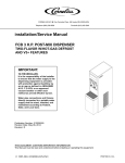
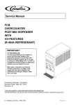
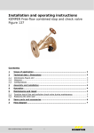
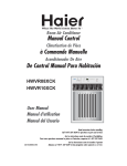
1
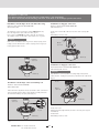
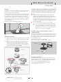
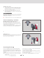
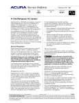
ACO H a u s t e c h n i k
User manual
0152.87.58 B
02/2011 edition
ACO Floor drains Variant-CR
DN 70, DN 100 and DN 150
This user manual contains important information! It
must be handed on to the end user who has to keep it
in a safe place!
Core bores
Stainless steel floor drains
with/without bell-shape odour seals
øa
b
Note:
Prior to installation, check the components for their
proper condition; do not fit damaged parts.
General installation information
■
For completion of drain body, relevant top and intermediate
sections for point drainage or channels for line drainage from
our current catalogue range have to be used.
■
For the installation of top sections, relevant user manuals are
attached to the components.
■
In the case of use in floors with fire resistance class (e. g.
F90), the special instructions for fire resistance floor drains
have to be observed when installing the drain body (refer to
assembly instructions of fire protection kit or ACO Fit-in).
■
Fig. 1 shows floor drain Variant-CR DN 100
b
(mm)
Øc
(mm)
150
--
150
350
8
150
9390.07.00
350
8
150
9292.07.00
150
--
150
Place drain body in existing recess. For core bores, observe
9192.07.00
350
8
150
the following table.
9392.07.00
350
8
150
9290.10.00
230
--
230
9190.10.00
425
8
230
9390.10.00
425
8
230
9292.13.00
230
--
230
9192.13.00
425
8
230
9392.13.00
425
8
230
9296.10.00
230
--
230
9396.13.00
230
--
230
9496.10.00
230
--
230
9496.13.00
230
--
230
9495.30.00
--
--
300
9495.35.00
--
--
300
Installation of floor drain
➜
øc
Nominal
width
DN 70
Designation
Floor drain
Variant-CR
Connection to the pipeline:
➜
Floor drain
Variant-CR
Drain socket DN 70
- in connection with hose element (included in scope of
supply), suitable for connection to SML pipe.
DN 100
- without hose element suitable for connection to plastic
pipe.
➜
Floor drain
single-body
Drain socket DN 100/DN 150
- suitable for SML pipe DN 100/DN 150.
■
■
When connecting to other pipe types, use relevant transition
DN 100/
elements.
DN 150
Grout drain body in recess/core bore.
Service Line
Tel. +49 (0) 36965 819–0
Fax +49 (0) 36965 819–361
Art. no.
Øa
(mm)
9290.07.00
9190.07.00
Industrial drains
9595.30.00
480
8
300
9595.35.00
480
8
300
9795.30.00
480
8
300
Information on odour seal:
The drain should not be used for disposal of solid matters - risk of blockage!
The odour seal must be fitted following connection of the drain to the drainage system at the latest!
Installation of bell-shape odour seal with roller ring
ACO Floor drains Variant-CR DN 70/DN 100
with inclination 90°.
Installation of dip-pipe odour seal
ACO Floor drains Variant-CR DN 70/DN 100
with inclination 1.5°.
The bell-shape odour seal must be rolled in without lubricant,
the roller ring must be placed into the lower groove.
Place odour seal vertically on drain socket (fig. 2) and roll in.
The rolling-in surface in the drain socket must be free of grease.
Insert odour seal and tilt in direction of arrow. Turn catch by 90°
(fig. 4).
Dismantling in reverse order.
Catch
Caution!
3.
If the odour seal with the roller ring is not located properly, risk of
leakage persists which leads to water escaping and no longer protecting against sewer odours.
Dip-pipe
odour seal
1.
2.
Drain body
Bell-shape
odour seal
Fig. 4
Installation of dip-pipe odour seal
ACO Industrial drains Variant-CR DN 100/DN 150
with inclination 90° and 1.5°.
Caution!
Drain body
Pay attention to correct position of sealing. Ridge must point to
outlet direction. Sealing offset must be positioned in the outlet notch
(fig. 5).
Fig. 2
Bucket
Installation of bell-shape odour seal with lip seal
ACO Floor drains Variant-CR DN 100
with inclination 90°
Sealing
Dip-pipe
odour seal
Lubricant must be applied to the lip seal and the odour seal must be
placed vertically into the drain socket. During assembly it must be
observed that sealing is properly seated (fig. 3).
Drain body
Bell-shape
odour seal
Fig. 5
Insert odour seal.
Tighten both nuts (right and left) at odour seal evenly across (spanner width 17).
Insert bucket.
Dismantling in reverse order.
Lip seal
Drain body
Fig. 3
Service Line
Tel. +49 (0) 36965 819–0
Fax +49 (0) 36965 819–361
2
ACO H a u s t e c h n i k
0152.87.58 B
Cleaning
Inspection and cleaning of floor drains are required every 6 months
at the latest or, as needed, in shorter time intervals. Odour seal
must be checked in case of requirement.
For cleaning purposes, the odour seal has to be dismantled. Drain
body and odour seal can be cleaned with fat-dissolving rinsing water
(e. g. water with commercial dishwashing agent). The sealing element at the odour seal must also be cleaned. Hood and stand pipe
of the stainless steel odour seal can be dismantled for cleaning purposes. Installation of odour seal must be carried out as per abovementioned instructions.
Replenish the drain body with water again (fig. 6).
Assembly of upper part (intermediate section) Variant-CR
Connection of sealing must be executed as described before. Upper
parts with adhering flanges/compression-sealing flanges are supplied with a sealing ring which must be fitted between drain body and
upper part.
■
During assembly of upper part, the correct seating of the
sealing ring (lip pointing downwards) is important (refer to
detail 1). The sealing ring (fig. 7) prevents the ingress of backflowing wastewater into the existing floor structure.
If seepage water shall be drained away from the lower sealing
membrane, the sealing ring must not be installed (refer to selection aid fig. 9/10).
■
In case of need, the upper part can be cut to length.
■
In case of upper parts with lateral inlet, the inlet pipe is
shoved into the lateral sleeve. Commercial plain conduit
sleeve systems DN 40 are suitable for floor drain upper
parts DN 70, plain conduit sleeve systems DN 50 are suitable for floor drain upper parts DN 100.
H 2O
Assembly of upper part (intermediate section)
of industrial drain
Contrary to the Variant-CR drain, a sealing ring with lips is used with
the industrial drain instead of a roller ring. During installation works,
this sealing ring has to be inserted in such a way between drain body and upper part (intermediate section) that upper edge is placed
on the drain flange (fig. 8).
Lubricant must be applied to the sealing lips.
Cut top sections must be chamfered in the socket area.
Fig. 6
Connection of sealing
➜ Apply sealing to the fixed flange (adhering flange) of the drain
body in accordance with the pertinent standards and regulations.
➜ With the compression-sealing flange, the sealing has to be
clamped with the loose flange subsequently. The contact
pressure of the nuts must be adapted to sealing used (refer
to manufacturer's indications) and the nuts must be tightened
evenly across. The max. torque is 20 Nm.
Sealing ring
Detail 2
Top section
Drain body
Fig. 8
Extension
Upper part
(intermediate
section)
Assembly of extension
In the case of high floor structures, the socket of the top section
must be adjusted by means of the extension art. no. 9392.27.31
(DN 70, Ø 125 mm), art. no. 9392.20.31 (DN 100, Ø 198 mm) or
art. no. 9595.20.31 (DN 100/DN150, Ø 242 mm).
In case of need, the extension can be cut to length.
For assembly, refer to top sections.
Upper part (intermediate
section) with lateral inlet
Drain body
Detail 1
Fig. 7
Service Line
Tel. +49 (0) 36965 819–0
Fax +49 (0) 36965 819–361
3
Assembly of top section
➜ In the case of floor drains which are equipped with continuously height-adjustable top sections, the retaining ring must be
shoved over the cylindrical socket of the top section with the
reinforcement ribs pointing downwards.
➜ Then, the top section must be inserted in the drain body in
such a way that the top section with its socket extends into the
drain for at least 5 mm.
Caution!
When using the retaining ring and if top section is grouted with liquid
material, please make sure that no grouting component enters the
drain through the retaining ring.
■
For further information, refer to top section installation manual.
Selection aid planning / installation
Retaining ring with seepage water bars (fig. 9)
When using the retaining ring with seepage water bars, seepage
water possibly accumulating may be drained into the drain base
body above the lower sealing level (e. g. when using the connected
sealing membrane as water-bearing level).
Possibly accumulating water in the outlet (e. g. with pipe blockage)
may enter the floor structure between the seepage water bars
or
Fig. 9
Sealing ring (fig. 10)
When using the sealing ring, the annular gap between drain body and
top section socket is closed buoyancy-safe. Seepage water is not
drained off when using the sealing ring.
Fig. 10
Potential equalisation
hing screw in the case of stainless steel drains with adhering flange.
This is marked with the symbol .
Connection of drains with compression-sealing flange is possible at
all screws - above the loose flange.
In the case of drains without earthing screw, connection with a suitable earthing clamp is possible.
The specifications of DIN VDE 0100-701 have to be observed!
In the case of buildings with a protective-equipotential bonding
via the main earthing terminal for the whole electrical plant, floor
drains must principally not be connected to an additional protectiveequipotential bonding if expertly installed in accordance with these
instructions.
In buildings, in which connection to the protective-equipotential bonding is recommended, connection can be carried out at existing ear-
Service Line
Tel. +49 (0) 36965 819–0
Fax +49 (0) 36965 819–361
4
ACO H a u s t e c h n i k
0152.87.58 B
Installation examples
Floor structure with sealing and thin bed process
Floor structure DN 100 with compression-sealing flange
Kitchen side room
Flexible joint
Floor tiles
(laid in gradient)
Tile adhesive
Compound sealing
Floor drain Variant-CR
with compressionsealing flange DN 100
with bell-shape
odour seal
Inclined screed
Sealing membrane
Insulation
Unfinished
concrete slab
Fig. 11
Note!
Especially in floors with fire resistance classes, the ACO Fit-in dry
construction kit, in connection with ACO floor drains and fire protection kit, complies with fire protection requirements up to R 120
(accessories).
➔ For further installation notes, refer to ACO Fit-in installation manual.
ACO Fit-in
dry construction kit
Fig. 12
Service Line
Tel. +49 (0) 36965 819–0
Fax +49 (0) 36965 819–361
5
0152.87.58 B
ACO Passavant GmbH
Im Gewerbepark 11c
36457 Stadtlengsfeld
Tel. +49 (0) 36965 819–0
Fax +49 (0) 36965 819–361
www.aco-haustechnik.de
The ACO Group. A strong family you can build on.
HT 905/03/2011 ● Vers:2.0 ● LTC
Subject to technical alterations.
●
Subject no. 0152.87.58 B
02/2011 edition