1
kÉï=~ë=çÑW==
MUKOMNR
áåi~Ä=pt
pçÑíï~êÉ=sÉêëáçå=NRKM
léÉê~íçêDë=j~åì~ä
båÖäáëÜ
Operator's Manual\rSoftware version 4.2.5
=
Table of contents
Sirona Dental Systems GmbH
Operator's Manual inLab SW
Table of contents
1
2
3
4
2
Introduction...............................................................................................................
9
1.1
Dear Customer, .............................................................................................
9
1.2
Copyright and trademark...............................................................................
9
General data.............................................................................................................
10
2.1
Certification ...................................................................................................
10
2.2
General safety information ............................................................................
10
2.3
Accessories ...................................................................................................
10
2.4
Structure of the manual .................................................................................
2.4.1 Identification of the danger levels.....................................................
2.4.2 Formats and symbols used ..............................................................
2.4.3 Conventions .....................................................................................
2.4.4 Manual formats (assistance) ............................................................
2.4.5 Odontogram used ............................................................................
2.4.6 File format ........................................................................................
11
11
11
12
12
12
13
Getting started..........................................................................................................
14
3.1
Installing the software ...................................................................................
14
3.2
Uninstalling the software ...............................................................................
15
3.3
Copy protection .............................................................................................
15
3.4
Downloading software ...................................................................................
15
3.5
Starting the software .....................................................................................
16
User interface ...........................................................................................................
17
4.1
Phase bar ......................................................................................................
4.1.1 ADMINISTRATION ..........................................................................
4.1.2 SCAN ...............................................................................................
4.1.3 MODEL ............................................................................................
4.1.4 DESIGN ...........................................................................................
4.1.5 PRODUCTION .................................................................................
17
18
18
18
18
18
4.2
Object bar......................................................................................................
19
4.3
Page palette ..................................................................................................
19
4.4
Tool wheel .....................................................................................................
20
4.5
Step menu.....................................................................................................
20
4.6
System menu ................................................................................................
4.6.1 Save case ........................................................................................
4.6.2 Save the case under a different name .............................................
4.6.3 Import case ......................................................................................
21
21
22
22
63 75 914 D3534
D3534.208.03.07.02 08.2015
Sirona Dental Systems GmbH
Table of contents
4.6.4
4.6.5
4.6.6
4.6.7
4.6.8
4.6.9
Exporting a case..............................................................................
License manager.............................................................................
Configuration ...................................................................................
Window mode..................................................................................
Current program version .................................................................
Exit program ....................................................................................
22
23
23
23
23
23
Start view......................................................................................................
4.7.1 Create a new job .............................................................................
4.7.2 Searching for a patient or case .......................................................
4.7.3 Editing case data.............................................................................
4.7.3.1 Editing case data ..............................................................
4.7.3.2 Removing a patient or case..............................................
4.7.3.3 Opening a case ................................................................
4.7.3.4 Add a new case ................................................................
24
24
25
25
25
25
25
25
Configuration ...........................................................................................................
26
5.1
Parameters...................................................................................................
26
5.2
Devices.........................................................................................................
5.2.1 inEos X5 ..........................................................................................
5.2.1.1 Resetting settings .............................................................
5.2.1.2 Calibration ........................................................................
5.2.2 inEos Blue .......................................................................................
5.2.2.1 Resetting settings .............................................................
5.2.2.2 Calibration ........................................................................
5.2.2.3 XYZ calibration .................................................................
5.2.3 Milling unit .......................................................................................
5.2.3.1 Editing settings .................................................................
5.2.3.2 Calibration ........................................................................
5.2.3.3 Changing instruments.......................................................
5.2.3.4 Removing the milling unit .................................................
37
38
38
38
39
39
39
39
40
40
41
41
41
5.3
Settings ........................................................................................................
5.3.1 ADA/FDI odontogram ......................................................................
5.3.2 Warning messages..........................................................................
5.3.3 Job database...................................................................................
5.3.4 Language ........................................................................................
5.3.5 MC XL milling ..................................................................................
5.3.6 Material configuration ......................................................................
41
41
42
42
42
42
43
5.4
Generic machine ..........................................................................................
43
Restoration types and design mode ........................................................................
44
6.1
Restoration types .........................................................................................
44
6.2
Design mode ................................................................................................
46
4.7
5
6
63 75 914 D3534
D3534.208.03.07.02
08.2015
3
båÖäáëÜ
Operator's Manual inLab SW
Table of contents
Sirona Dental Systems GmbH
Operator's Manual inLab SW
6.3
7
4
Biogenerics ...................................................................................................
6.3.1 General information on biogenerics .................................................
6.3.2 Biogeneric Individual ........................................................................
6.3.3 Biogeneric Copy...............................................................................
6.3.4 Biogeneric Reference.......................................................................
48
48
48
49
49
Editing orders ...........................................................................................................
50
7.1
50
50
51
52
52
52
54
55
55
55
56
56
57
58
59
60
60
61
61
62
62
63
63
63
64
64
65
66
67
69
71
74
75
75
75
76
Tools and functions of the page palette ........................................................
7.1.1 View options .....................................................................................
7.1.2 Tools ................................................................................................
7.1.2.1 Buccal registration.............................................................
7.1.2.2 Buccal bite tools ................................................................
7.1.2.3 Shaping .............................................................................
7.1.2.4 Cut out model areas ..........................................................
7.1.2.5 Correcting defects .............................................................
7.1.2.6 Resetting the model ..........................................................
7.1.2.7 Trimming ...........................................................................
7.1.2.8 Entering the preparation margin........................................
7.1.2.9 Entering the baseline on the gingival mask.......................
7.1.2.10 Positioning.........................................................................
7.1.2.11 Recalculating restorations .................................................
7.1.2.12 Designing ..........................................................................
7.1.2.13 Biogeneric variation...........................................................
7.1.2.14 Reduce ..............................................................................
7.1.2.15 Contacts ............................................................................
7.1.2.16 Adjusting sprue location ....................................................
7.1.2.17 Positioning blocks..............................................................
7.1.2.18 Incisal variation..................................................................
7.1.2.19 Using a gingival mask .......................................................
7.1.2.20 Splitting..............................................................................
7.1.2.21 Scaling...............................................................................
7.1.2.22 Creating a cavity design ....................................................
7.1.2.23 Tool wheel .........................................................................
7.1.2.24 Adjusting connectors .........................................................
7.1.2.25 Adjusting the baseline of the pontic...................................
7.1.3 Display objects .................................................................................
7.1.4 Activating analysis............................................................................
7.1.5 Articulation .......................................................................................
7.1.6 Smile Design ....................................................................................
7.1.6.1 Loading reference image...................................................
7.1.6.2 Setting reference points ....................................................
7.1.6.3 Adjusting the canthi distance.............................................
7.1.6.4 Aligning the model.............................................................
63 75 914 D3534
D3534.208.03.07.02 08.2015
Sirona Dental Systems GmbH
Table of contents
7.1.6.5 Auxiliary planes ................................................................
Case details.....................................................................................
76
76
7.2
ADMINISTRATION phase............................................................................
77
7.3
SCAN phase.................................................................................................
7.3.1 Image catalogs with inEos Blue ......................................................
7.3.1.1 Working with the image catalog........................................
7.3.1.2 Adding image catalogs .....................................................
7.3.1.3 Recycle bin .......................................................................
7.3.2 Live image .......................................................................................
7.3.3 3D Preview ......................................................................................
7.3.4 Take a scan.....................................................................................
7.3.4.1 inEos X5 ...........................................................................
7.3.4.2 inEos Blue ........................................................................
7.3.4.3 Additional acquisitions ......................................................
7.3.4.4 Finishing the phase ..........................................................
82
82
83
85
86
86
87
88
88
96
103
103
7.4
MODEL phase..............................................................................................
7.4.1 Editing the model.............................................................................
7.4.2 Buccal registration...........................................................................
7.4.3 Manual correlation for image fields .................................................
7.4.4 Buccal bite tools ..............................................................................
7.4.5 Set model axis.................................................................................
7.4.6 Editing the jaw ridge line .................................................................
7.4.7 Trimming the preparation ................................................................
7.4.8 Entering the preparation margin......................................................
7.4.9 Defining the insertion axis ...............................................................
7.4.9.1 Preparing the right insertion axis ......................................
7.4.9.2 Redefining the insertion axis ............................................
7.4.9.3 Displaying the insertion axis cylinder................................
7.4.9.4 Setting the insertion axis for the gingival element ............
7.4.10 Finishing the phase .........................................................................
103
103
104
107
107
108
109
110
111
114
114
115
116
116
116
7.5
DESIGN phase.............................................................................................
7.5.1 Adjusting parameters ......................................................................
7.5.2 Morphology step..............................................................................
7.5.3 Positioning step ...............................................................................
7.5.4 Editing the restoration .....................................................................
7.5.5 Finishing the phase .........................................................................
116
117
117
118
118
118
7.6
PRODUCING phase.....................................................................................
7.6.1 Changing the production machine...................................................
7.6.2 Changing the milling settings ..........................................................
7.6.3 Selecting the color...........................................................................
7.6.4 Positioning restorations in the block................................................
7.6.5 Changing block sizes ......................................................................
7.6.6 Exporting a restoration ....................................................................
119
119
119
119
120
120
121
7.1.7
63 75 914 D3534
D3534.208.03.07.02
08.2015
5
båÖäáëÜ
Operator's Manual inLab SW
Table of contents
Sirona Dental Systems GmbH
Operator's Manual inLab SW
7.6.7
8
6
Starting the milling process .............................................................. 121
Design examples...................................................................................................... 122
8.1
Abutment - Biogeneric individual - MultiLayer ...............................................
8.1.1 Create a new restoration..................................................................
8.1.2 Scanning a preparation ....................................................................
8.1.3 Editing the model .............................................................................
8.1.4 Bite registration ................................................................................
8.1.5 Set model axis..................................................................................
8.1.6 Mask areas.......................................................................................
8.1.7 Select Scanbody ..............................................................................
8.1.8 Editing the baseline..........................................................................
8.1.9 Define restoration axis .....................................................................
8.1.10 Adjusting parameters .......................................................................
8.1.11 Editing the restoration ......................................................................
8.1.12 Grinding of restoration layers ...........................................................
122
122
122
123
123
123
123
123
124
125
125
125
126
8.2
Abutment - Biogeneric individual...................................................................
8.2.1 Create a new restoration..................................................................
8.2.2 Scanning a preparation ....................................................................
8.2.3 Editing the model .............................................................................
8.2.4 Bite registration ................................................................................
8.2.5 Set model axis..................................................................................
8.2.6 Mask areas.......................................................................................
8.2.7 Select Scanbody ..............................................................................
8.2.8 Editing the baseline..........................................................................
8.2.9 Define restoration axis .....................................................................
8.2.10 Adjusting parameters .......................................................................
8.2.11 Editing the restoration ......................................................................
8.2.12 Grinding the restoration....................................................................
126
126
127
127
127
127
128
128
129
130
130
130
130
8.3
Abutment - framework ...................................................................................
8.3.1 Create a new restoration..................................................................
8.3.2 Scanning a preparation ....................................................................
8.3.3 Editing the model .............................................................................
8.3.4 Bite registration ................................................................................
8.3.5 Set model axis..................................................................................
8.3.6 Mask areas.......................................................................................
8.3.7 Select Scanbody ..............................................................................
8.3.8 Editing the baseline..........................................................................
8.3.9 Define restoration axis .....................................................................
8.3.10 Adjusting parameters .......................................................................
8.3.11 Editing the restoration ......................................................................
8.3.12 Grinding the restoration....................................................................
131
131
131
131
132
132
132
132
133
134
134
134
134
8.4
Bars ............................................................................................................... 135
63 75 914 D3534
D3534.208.03.07.02 08.2015
Sirona Dental Systems GmbH
Table of contents
8.4.1
8.4.2
8.4.3
8.4.4
8.4.5
8.4.6
8.4.7
8.4.8
8.4.9
8.4.10
8.4.11
Create a new restoration .................................................................
Scanning a preparation ...................................................................
Editing the model.............................................................................
Bite registration ...............................................................................
Set model axis.................................................................................
Mask areas......................................................................................
Drawing the preparation margin ......................................................
Defining axes...................................................................................
Adjusting parameters ......................................................................
Editing the restoration .....................................................................
Grinding the restoration...................................................................
135
136
136
136
136
137
137
137
138
139
139
8.5
Attachments .................................................................................................
8.5.1 Create a new restoration .................................................................
8.5.2 Scanning a preparation ...................................................................
8.5.3 Editing the model.............................................................................
8.5.4 Bite registration ...............................................................................
8.5.5 Set model axis.................................................................................
8.5.6 Mask areas......................................................................................
8.5.7 Drawing the preparation margin ......................................................
8.5.8 Defining axes...................................................................................
8.5.9 Adjusting parameters ......................................................................
8.5.10 Editing restorations..........................................................................
8.5.11 Grinding the restoration...................................................................
139
139
140
140
141
141
141
141
141
142
142
143
8.6
Model............................................................................................................
8.6.1 Create a new restoration .................................................................
8.6.2 Scanning a preparation ...................................................................
8.6.3 Editing the model.............................................................................
8.6.4 Bite registration ...............................................................................
8.6.5 Set model axis.................................................................................
8.6.6 Editing restorations..........................................................................
8.6.7 Aligning the model...........................................................................
8.6.8 Adjusting parameters ......................................................................
8.6.9 Segmentation ..................................................................................
8.6.10 Undercutting segments ...................................................................
8.6.11 Placing pins .....................................................................................
8.6.12 Closing the model............................................................................
144
144
144
145
145
145
145
146
146
146
147
148
149
8.7
Anatomical or reduced directly screwed-on bridges.....................................
8.7.1 ADMINISTRATION phase...............................................................
8.7.1.1 Create a new restoration ..................................................
8.7.1.2 Implant connection ...........................................................
8.7.1.3 Selecting scanbody types.................................................
8.7.1.4 Selecting the grinding device............................................
8.7.1.5 Material selection..............................................................
149
149
149
150
150
150
150
63 75 914 D3534
D3534.208.03.07.02
08.2015
7
båÖäáëÜ
Operator's Manual inLab SW
Table of contents
Sirona Dental Systems GmbH
Operator's Manual inLab SW
8.7.2
8.7.3
8.7.4
8.7.5
9
10
SCAN phase ....................................................................................
8.7.2.1 Jaw scanning.....................................................................
8.7.2.2 Scanning implant positions................................................
MODEL phase..................................................................................
DESIGN phase.................................................................................
PRODUCING phase ........................................................................
151
151
151
152
152
153
Tips and Tricks ......................................................................................................... 154
9.1
Service program ............................................................................................ 154
9.2
Shortcut keys ................................................................................................ 155
Sirona Connect portal............................................................................................... 159
10.1
Starting the Sirona Connect portal ................................................................ 159
10.2
Log out of the Sirona Connect software at the portal .................................... 159
10.3
Order list........................................................................................................ 159
10.4
Restoration data ............................................................................................ 159
10.5
Order information .......................................................................................... 159
10.6
Additional information.................................................................................... 160
10.7
Displaying the order sheet ............................................................................ 160
10.8
Checking the model ...................................................................................... 160
10.9
Accepting/rejecting an order ......................................................................... 161
10.10 Order list appears automatically.................................................................... 161
10.11 Chat function ................................................................................................. 161
11
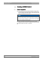
Creating a CEREC Guide 2...................................................................................... 162
11.1
Optical impression......................................................................................... 162
11.2
3D x-ray and implant planning ...................................................................... 163
11.3
Design and development of the CEREC Guide 2 ......................................... 165
11.4
Surgical intervention...................................................................................... 167
Index......................................................................................................................... 168
8
63 75 914 D3534
D3534.208.03.07.02 08.2015
Sirona Dental Systems GmbH
1 Introduction
Operator's Manual inLab SW
1.1 Dear Customer,
1
Introduction
1.1 Dear Customer,
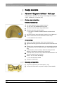
Thank you for purchasing your inLab SW 15 software from Sirona.
General description of inLab SW
In conjunction with the X5 inEos and inEos Blue scanners as well as the
inLab MC XL and inLab MC X5 devices, this software enables you to
produce computer-assisted dental restorations from various materials.
Improper use and handling can create hazards and cause damage.
Therefore, please read and carefully follow this manual and the relevant
operating instructions. Always keep them within easy reach.
Also pay attention to the safety instructions to prevent personal injury and
material damage.
Your
inLab team
Your Team
1.2 Copyright and trademark
Copyright
© Sirona Dental Systems GmbH. All rights reserved.
Copyright
The information contained in this manual may be changed without notice.
The software and all related documentation are protected by copyright.
You must therefore handle it in the same way as any other protected
material.
Anyone who copies this software to any medium for any purpose other
than his own personal use without the written permission of Sirona Dental
Systems will be liable to prosecution.
Trademarks
Microsoft® and Windows 7® are registered trademarks.
Trademarks
WindowsTM is a trademark of Microsoft Corporation.
All other trademarks are the property of their respective holders.
Notes on 3rd party code libraries must be stored in license.pdf in the
installation directory.
3rd party code libraries
63 75 914 D3534
D3534.208.03.07.02
08.2015
9
båÖäáëÜ
In order to master the system safely, you should train on the exercise
model using the described examples.
2 General data
Sirona Dental Systems GmbH
2.1 Certification
Operator's Manual inLab SW
2
General data
Please read this document completely and follow the instructions exactly.
You should always keep it within reach.
Original language of the present document: German
2.1 Certification
CE mark
This product bears the CE mark in accordance with the provisions of the
Council Directive 93/42/EEC of June 14, 1993 concerning medical
devices (MDD).
CE mark, general
2.2 General safety information
Only use original software
Only use original software
Only use original software or software which has been released by
Sirona. To produce restorations and equipment, manipulated or nonreleased software components must not be used.
Software and software components must not be installed using incorrect
data.
Please check that each installed component has been granted approval
in its country. Contact your dealer for more information.
Restoration to be checked by trained personnel
Checking the restoration
Each restoration which is performed with this software must be checked
for suitability by a trained person (e.g. dental technician or dentist).
For the USA only
For the USA only
CAUTION: According to US Federal Law, this product may be sold only
to or by instruction of physicians, dentists, or licensed professionals.
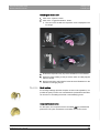
2.3 Accessories
In order to ensure product safety, this device may be operated only with
original Sirona accessories or third-party accessories expressly approved
by Sirona. The user is responsible for any damage resulting from the use
of non-approved accessories.
Product safety
10
63 75 914 D3534
D3534.208.03.07.02 08.2015
Sirona Dental Systems GmbH
2 General data
Operator's Manual inLab SW
2.4 Structure of the manual
2.4 Structure of the manual
2.4.1
Identification of the danger levels
To prevent personal injury and material damage, please observe the
warning and safety information provided in the present operating
instructions. Such information is highlighted as follows:
DANGER
An imminent danger that could result in serious bodily injury or death.
WARNING
CAUTION
A possibly dangerous situation that could result in slight bodily injury.
NOTICE
A possibly harmful situation which could lead to damage of the product
or an object in its environment.
IMPORTANT
Application instructions and other important information.
Tip: Information on making work easier.
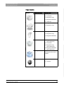
2.4.2
Formats and symbols used
The formats and symbols used in this document have the following
meaning:
Prerequisite
Requests you to do something.
1. First action step
2. Second action step
or
➢
Alternative action
Result
➢ Individual action step
63 75 914 D3534
D3534.208.03.07.02
08.2015
See "Formats and symbols
used [ → 11]"
Identifies a reference to another text
passage and specifies its page
number.
● List
Designates a list.
"Command / menu item"
Indicates commands, menu items or
quotations.
11
båÖäáëÜ
A possibly dangerous situation that could result in serious bodily injury
or death.
2 General data
Sirona Dental Systems GmbH
2.4 Structure of the manual
Operator's Manual inLab SW
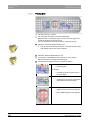
2.4.3
Conventions
Example
Meaning
Click
Single pressing and subsequent release of the left
mouse button or the left trackball button on the
acquisition unit
Double-click
Double pressing and release in quick succession of
the left mouse button or left trackball button on the
acquisition unit
Moving the mouse On the acquisition unit: Moving the trackball in the
in one direction
corresponding direction.
Seizing a point
Pressing the left mouse button (left trackball button
on the acquisition unit) and keeping it pressed.
For acquisitions
with the CEREC
Bluecam: Actuate
foot switch
The same function as: Pressing the left trackball
button on the acquisition unit or the left mouse
button.
"Ctrl+N"
On the keyboard: Press the Ctrl and N keys
simultaneously.
Drag & drop
.
Press and hold an element (e.g. a pictograph) and
drop / release it onto a potential destination.
2.4.4
Manual formats (assistance)
You can access the manual via the Help button or by pressing "F1".
HTML
The PDF-format user manual can be found on the supplied software DVD
or on the Internet (http://www.sirona.com/manuals).
PDF
This format is page-oriented and is well suited for printing out the desired
pages.
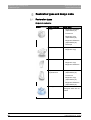
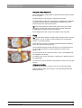
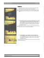
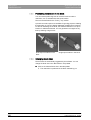
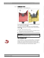
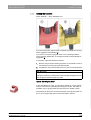
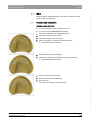
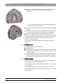
2.4.5
Odontogram used
The software can be adjusted to the international odontogram (FDI) or the
USA odontogram (ADA) (ADA/FDI odontogram [ → 41]).
In this documentation teeth are named as follows:
12
Principle:
FDI
(#ADA)
Example:
13
(#6)
63 75 914 D3534
D3534.208.03.07.02 08.2015
Sirona Dental Systems GmbH
2 General data
Operator's Manual inLab SW
2.4 Structure of the manual
2.4.6
File format
You can assign one or more orders to any dentist in the software.
Depending on the processing status, an order comprises multiple optical
impressions, the virtual models reconstructed from them and one or more
virtual restorations.
The software uses its own file format (*.lab) to export an order. This
format contains all of the order data. LAB files can be opened with other
inLab software installations. Under certain circumstances, older software
versions cannot open data exports from a more recent version.
båÖäáëÜ
Using this interface license, models or restorations can also be exported
in *.stl format for the further processing of this data in other software.
Using this license, *.stl data can also be imported into the inLab SW to
make constructions on them.
63 75 914 D3534
D3534.208.03.07.02
08.2015
13
3 Getting started
Sirona Dental Systems GmbH
3.1 Installing the software
Operator's Manual inLab SW
3
Getting started
3.1 Installing the software
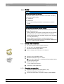
NOTICE
Fragment: Initial installation
Initial installation without inEos X5 / Blue
Perform the initial installation of the software without connecting inEos
X5 / Blue.
The software requires the 2.00 firmware version of the USB license stick.
Update the firmware version if necessary. For more information, refer to
the section License manager [ → 23].
Firmware V2.00
You need at least one inLab 4-PC V 1.0.1 for the software. An inLab 4 PC
V 3.0.1 is recommended.
Prerequisite
Use the version of the license manager provided with this version to
import licenses from the license certificate provided.
NOTICE
Administrator rights
Installation only with administrator rights
You must have administrator rights on the PC on which you want to
install the software!
✔ The license stick firmware is available in version 2.00.
✔ The PC is powered up and all programs are terminated.
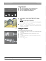
1. Insert the DVD in the DVD drive.
The setup program starts automatically.
2. If this is not the case, run the "Setup.exe" file in the root directory of
the DVD.
The installation wizard opens.
3. Click on the "OK" button.
4. Select the language for the installation and click on “"Next" ”.
5. In the next dialog, click the "Next" button.
6. Select the language for the software from the drop-down menu, and
select the region you are in from the download menu below it. Then
click on "Next" .
7. In the next step, you can choose the installation folder. You can also
change the path for the patient data folder and the path for the CAM
data. Click on "Next" .
8. Read the license agreement carefully. If you accept the license
agreement, then activate the "I accept the terms in the license
agreement" option button and click the "Next" button.
The installation starts. This may take several minutes.
9. Following successful installation, click on the "Start" button to
complete the installation and to start the application immediately after
this.
Tip: If you do not want to start the application immediately, remove
the tick from the "Start application directly" check box and then click
on the "Exit" button. This installation program closes.
14
63 75 914 D3534
D3534.208.03.07.02 08.2015
Sirona Dental Systems GmbH
3 Getting started
Operator's Manual inLab SW
3.2 Uninstalling the software
3.2 Uninstalling the software
✔ The program is closed.
1. Click on "StartAll Programs / Sirona Dental SystemsinLab
SWToolsDeinstallation" to uninstall the software.
During the uninstall procedure, you will be asked whether you
want to delete the patient data or the entries in the registration
database (e.g. the calibration data).
2. Depending on your decision, click either the "Yes" or "No" button.
The software is uninstalled.
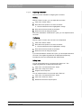
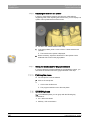
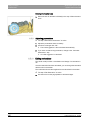
3.3 Copy protection
The software can be started only when the USB license stick is plugged
in. The USB license stick is included in the scope of supply of the units. If
you require additional licenses, please contact your dealer.
Always keep the USB license stick near the unit.
All authorizations (software licenses) can be installed as electronic
licenses on the USB license stick. You must enter a 25-digit license key
for this purpose.
You will receive the license key along with the unit. Alternatively, you can
order it separately from your dealer.
Following an update, you may require a new license that is not available
on your USB license stick. For more information, refer to the section
License manager [ → 23].
3.4 Downloading software
Auto-update, Sirona Connect Center
Fragment: CEREC SW auto-update
IMPORTANT
Fragment PC connected to the Internet.
In order to use the auto-update function, the PC must be connected to
the Internet.
During the installation of inLab SW, the auto-update function is also
installed as a part of the Sirona Connect Center. You can conveniently
download and install future software updates of inLab SW through the
Internet.
Once an update is ready for download, you are notified of this
automatically through a dialog box.
Service packs
Service packs
To keep your software updated, regularly check whether new service
packs are available.
inLab SW
Visit the Sirona website at www.sirona.com. In the product area for digital
dental care, you will find the download area with the products for “inLab
laboratory solutions”.
63 75 914 D3534
D3534.208.03.07.02
08.2015
15
båÖäáëÜ
USB license stick inLab + inLab stack
3 Getting started
Sirona Dental Systems GmbH
3.5 Starting the software
Operator's Manual inLab SW
Update
Update
You have to pay for major software updates, and these also require a
license. If you do not have a new license, you can only work in the demo
version.
Contact your dealer for information on how to obtain new licenses for an
update.
3.5 Starting the software
✔ The inLab SW software is installed. You will find the start icon on the
desktop.
✔ The USB license stick is connected with a valid, current license.
➢ Double-click the inLab SW start icon.
or
➢ Click on "StartAll Programs/ Sirona Dental SystemsinLab
SWinLab SW 4".
The software is started.
16
63 75 914 D3534
D3534.208.03.07.02 08.2015
Sirona Dental Systems GmbH
4 User interface
Operator's Manual inLab SW
4.1 Phase bar
User interface
båÖäáëÜ
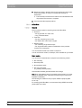
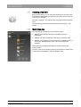
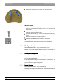
4
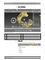
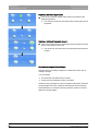
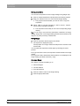
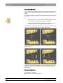
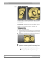
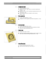
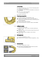
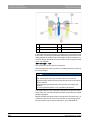
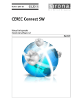
Overview of the user interface
A
System menu
F
Main window
B
Phase bar
G
Tool wheel
C
Information dialog
H
Step menu
D
Opens a Sirona Connect chat
I
Object bar
E
Page palette
J
Restoration selector
Legend inLab SW
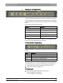
4.1 Phase bar
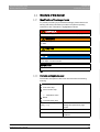
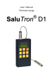
The workflow is illustrated in the software in 5 phases.
$'0,1,675$7,21
6&$1
02'(/
'(6,*1
352'8&(
Phase bar
● ADMINISTRATION
● SCAN
● MODEL
● DESIGN
● PRODUCE
63 75 914 D3534
D3534.208.03.07.02
08.2015
17
4 User interface
Sirona Dental Systems GmbH
4.1 Phase bar
Operator's Manual inLab SW
4.1.1
ADMINISTRATION
In this phase, you can perform the following:
Administration phase; inLab SW 4.0
● Create restorations and determine their type
● Specify a production machine
● Select material
4.1.2
SCAN
In this phase, you can perform the following:
● Acquisitions with inEos X5/Blue
- lower jaw,
- upper jaw,
- buccal bite registration
inLab SW
● View a 3D preview of the acquisitions
● Add additional image catalogs
● Import STL scan data
4.1.3
MODEL
In this phase, you can perform the following:
inLab SW
● Edit the model
● Check or redefine the bite situation
● Align the models
● Check the trimmed model or manually re-trim
● Check, correct or re-enter the preparation margin
● Define insertion axes
● Define jawline and restoration positions
● Define restoration axes if necessary (abutments and telescopes only)
● Select the patient photo for Smile Design
4.1.4
DESIGN
In this phase, you can perform the following:
inLab SW
● Select tooth form
● Position and scale restorations
● Individually change restoration parameters
● Have initial restoration suggestions generated
● Design restorations individually
4.1.5
PRODUCTION
In this phase, you can perform the following for each restoration:
● Specify a production machine
● Define manufacturing options (not possible for all materials)
18
63 75 914 D3534
D3534.208.03.07.02 08.2015
Sirona Dental Systems GmbH
4 User interface
Operator's Manual inLab SW
4.2 Object bar
● Determine the block size
● Check and adapt the positioning of the restoration in the block
● Define the sprue location of the restoration
● Start the manufacturing process
● Export the restoration/model for the inLab CAM SW or as *.stl files
(additional license required)
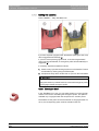
4.2 Object bar
The buttons for restoration selection are located in the object bar.
Each restoration is represented by a tooth or a bridge symbol with the
corresponding tooth number(s). You can switch back and forth between
the teeth by clicking on the corresponding icon.
Active elements are highlighted in orange.
If restorations span multiple tooth positions or two objects per tooth
position are selectable for multilayer, the object bar is extended
downwards. You can change between different active elements in the
extended area.
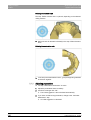
4.3 Page palette
Various functions and options are offered to you in the page palette,
depending on the step currently active.
You can open several page palettes at the same time. Initially all page
palettes opened on the right side of the main window in a fixed state. In
this state all opened page palettes share the height available there.
Fragment page palette
Should this display be inadequate for you, you can remove any page
palette of your choosing from the fixed state of the magnet bar. To do this,
press and hold the left mouse button on the header of the page palette
and then drag the palette to the desired position within the main window.
Tip: If you are using inLab SW in window mode or on multiple screens,
then you can also pull the page palettes out of the application window and
position them in any point on your screen.
All changes to a page palette (size and position) are saved separately for
each step. You can therefore configure each work step as you want.
IMPORTANT
If a page palette is closed, the size and position are retained when next
opened. If a page palette is stuck back on the magnet bar, however, the
saved size and position are lost.
In order to affix a page palette back onto the magnet bar on the right side,
drag any page palette over the magnet bar on the right side. When the
magnet bar lights up, you can then release the left mouse button. Click
the left mouse button. The page palette will now automatically put itself
back in order with the other page palettes.
To close a page palette, click on the right button in the page palette
header or once more on the respective right button in the magnet bar.
63 75 914 D3534
D3534.208.03.07.02
08.2015
19
båÖäáëÜ
inLab bridges
4 User interface
Sirona Dental Systems GmbH
4.4 Tool wheel
Operator's Manual inLab SW
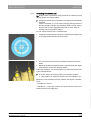
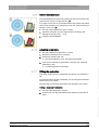
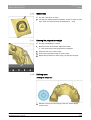
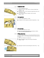
4.4 Tool wheel
In the MODEL and DESIGN phases, the tool wheel provides the most
common tools for simplifying access. The tools available vary depending
on the current step.
CEREC SW 4+inLab SW description
1. Right-click in the workspace.
The tool wheel opens.
2. Click with the right mouse button anywhere in the workspace.
The tool wheel moves to the position of the mouse pointer.
3. Select a tool.
The selected tool is available. The tool wheel closes
automatically.
You also can close the tool by clicking in the workspace with the left
mouse button.
4.5 Step menu
Each phase is divided into steps. They are shown in the step menu at the
bottom edge of the screen. The step menu changes depending on which
phase the current restoration is located in at the time.
General description
This menu guides you through the process step-by-step. The system runs
through all steps in a phase with the restoration(s). Changes in the
individual steps are accepted by clicking on the next step.
The double arrow keys can be used to switch between phases.
Double arrow keys
20
63 75 914 D3534
D3534.208.03.07.02 08.2015
Sirona Dental Systems GmbH
4 User interface
Operator's Manual inLab SW
4.6 System menu
4.6 System menu
In the system menu, you can:
Fragment introduction
● Switches to the start window to start a new case
Fragment list 1
● Save case
● Save the case under a different name
● Import case
● Export case
● Call up App Center/start plug-ins
Fragment list 2
● Open license manager
Fragment list 3 Connect
båÖäáëÜ
● Configure hardware and software
● Change window mode
● Open help information
● Exit program
Opening system menu
Opening system menu
➢ Move the mouse cursor to the top of the window.
or
➢ Click the start window button.
The system menu is displayed.
Closing system menu
Closing system menu
➢ Click the start window button.
or
➢ Click into the main window with the left mouse button.
The system menu is closed.
4.6.1
Save case
In this dialog, you can save the actual case.
➢ Select "Save Case" in the system menu.
The current processing status of the case is saved.
Tip: How you are able to save individual restorations or export them for
the inLab CAM SW is described in the section “Exporting a
restoration [ → 121]”.
Save restorations or export them for the stack software
63 75 914 D3534
D3534.208.03.07.02
08.2015
21
4 User interface
Sirona Dental Systems GmbH
4.6 System menu
Operator's Manual inLab SW
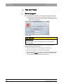
4.6.2
Save the case under a different name
This dialog allows you to save the current case under a new name or
assign it to a different patient.
1. Select "Save Case As..." in the system menu.
The patient list is opened.
2. Select the appropriate patient.
or
➢ Create a new patient via "Add New Patient" .
3. You can give the case a new name in the "Case" column via the
pencil icon.
4.6.3
Import case
✔ The LAB file, DXD file, CMG.DXD file (or older CDT files) of a case
are located on the inLab4 PC or a storage medium connected to it.
1. Click the "Import Case..." button in the system menu.
The "Import Case..." dialog box opens.
2. Select the folder where the case is located.
3. Select the relevant file.
4. Click the "Open" button.
The case is then imported and opened.
Depending on the type of restoration, only the optical impression is
opened.
4.6.4
Exporting a case
You can store a case in any location.
Exporting inLab SW
✔ You have opened a case in the software.
1. Click on the "Export Case..." button in the system menu.
The "Export Case..." dialog box opens.
2. Select the target folder to which you want to export the case.
3. Assign any name to the case.
4. Click on the "Save" button.
The case is exported as an LAB file.
If you want to save the model in *.stl format (interface license required),
select the appropriate file format from the dialog box and continue as
described in points 2 to 4.
If you would like to transfer the optical impression to another PC, you can
use a USB stick or a network drive for this purpose.
Transferring
22
63 75 914 D3534
D3534.208.03.07.02 08.2015
Sirona Dental Systems GmbH
4 User interface
Operator's Manual inLab SW
4.6 System menu
4.6.5
License manager
The license manager is used for the installation of new software licenses
on the USB license stick. To do this, start the license manager via the
system menu and follow the instructions on the screen. Keep the license
certificate with 25-digit license key ready, which you either obtained with
the unit or ordered separately from your dealer.
Tip: You can also start the license manager via "StartAll Programs /
Sirona Dental SystemsinLab SWToolsLicense Manager".
To activate the license you must have an Internet connection and the
USB license stick must be connected.
Licenses and code libraries
For information on licenses and code libraries from third parties, see
licenses.pdf. The file is in the installation directory under "C:/Programs/
Sirona Dental Systems/CADCAM".
4.6.6
Configuration
The configuration is described in the section “Configuration [ → 26]”.
4.6.7
Window mode
The "Window Mode" function can be used to exit full-screen mode or
enter it again.
4.6.8
Current program version
If you click on the lettering "inLab" in the phase tab, you obtain
information on the current program version.
CEREC SW 4 + CAM+Connect
4.6.9
Exit program
The "Exit" function can be used to close the software.
Closing CEREC SW 4 + inLab SW
63 75 914 D3534
D3534.208.03.07.02
08.2015
23
båÖäáëÜ
License texts and third-party libraries
4 User interface
Sirona Dental Systems GmbH
4.7 Start view
Operator's Manual inLab SW
4.7 Start view
In the start view you can perform the following:
inLab SW 4 start window options
● Create a new job
● Edit order data
● Search patient database,
Switching to the start view
Switch to the start window
You can switch to the start view at any time.
1. Open the system menu.
2. Click on the "Start Screen" button.
4.7.1
Create a new job
In the data structure, orders are uniquely identified by one of the following
two entries:
● Name of the dentist and name of the patient
or
● Name of the dentist and order number
Add order
1. If the dentist concerned has already been created, click on the
dentist.
2. Click on the "Add New Order" button.
A job order card opens. The name of the dentist that you
preselected is then suggested.
3. Enter the name of the dentist and the name of the patient.
or
➢
Enter the name of the dentist and the order number.
Once you have entered enough information, the step "Add New
Case" is enabled.
4. Click on the "Add New Case" button.
The program switches over to the "ADMINISTRATION" phase.
24
63 75 914 D3534
D3534.208.03.07.02 08.2015
Sirona Dental Systems GmbH
4 User interface
Operator's Manual inLab SW
4.7 Start view
4.7.2
Searching for a patient or case
You can view individual patients by searching for them
1. Click into the search text box.
2. Enter the surname or the patient ID.
3. Click the magnifying glass to start.
The program now shows all the search results.
Tip: You can also enter the initial letter of the dentist or patient click on the
magnifying glass. The list is sorted accordingly.
4.7.3
4.7.3.1
Editing case data
Editing case data
✔ You are in the job list.
båÖäáëÜ
1. Click on the pencil icon in the desired column.
The fields that can be changed are active.
2. Click on the "Edit Order" step in the step menu.
The job order card is opened for editing.
3. Carry out the changes.
4. Confirm the change by clicking on the tick icon in the relevant line.
The changes are saved in the memory.
5. You can discard the changes by clicking on the cross (X) in the
relevant line.
4.7.3.2
Removing a patient or case
✔ You are in the job list.
1. Click on the trash can icon in the "Order" column to remove a patient,
or in the "Case" column to remove a case.
2. Confirm the deletion by clicking the "Ok" button.
The patient or case is deleted.
4.7.3.3
Opening a case
✔ You have found the associated order in the overview.
inLab SW
➢ Click on the folder icon.
The case opens.
4.7.3.4
Add a new case
✔ You have found the associated order in the overview.
inLab SW
1. Select the dentist and the patient.
2. Click on the "Add New Case" step in the step menu.
The program switches over to the "ADMINISTRATION" phase.
63 75 914 D3534
D3534.208.03.07.02
08.2015
25
5 Configuration
Sirona Dental Systems GmbH
5.1 Parameters
Operator's Manual inLab SW
5
Configuration
The "Configuration" menu contains the following submenus:
Overview
● Parameters
● Devices
● Settings
● Apps
Fragment not in Japan
5.1 Parameters
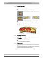
The "Parameters" menu is structured by restoration type. You can make
the settings for each of the following restoration types.
General information
The changes in the values are displayed graphically.
Changed parameter settings are accepted for all initial suggestions here.
Tip: If you want to change the parameter values only for one restoration,
do this in the DESIGN phase in the step "Restoration Parameters" .
Tip
Parameter profiles
Fragment parameter profiles
In the "Configuration" menu you can define parameter profiles from inLab
SW version 15.0 onwards. Through this menu you can define and save
different parameter sets for all restoration types.
1. Duplicate the default settings with the manufacturer specifications by
clicking on the tick icon.
2. Give the profile a unique name and confirm the entry with the tick
icon.
3. Adjust the parameters to your needs and then save them.
You can then use these default settings both as global and local
parameters.
4. You can select the newly created profile as a favorite by clicking on
the star icon.
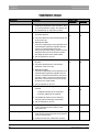
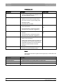
Crown, inlay, veneer parameters
26
63 75 914 D3534
D3534.208.03.07.02 08.2015
Sirona Dental Systems GmbH
5 Configuration
Operator's Manual inLab SW
5.1 Parameters
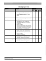
Crown, inlay, onlay and veneer
Parameters
Description
Default value
Crown
Inlay/
Onlay
Veneer
Spacer
● Possibility for setting the space for the
80µm
fastening material below the restoration. Acts
up to the preparation margin. A different
spacer for radial and occlusal can set for
crowns.
80µm
80µm
Marginal Adhesive Gap
● Adjust width of space on preparation margin.
-
60µm
-
-
-
500µm
0µm
0µm
0µm
25µm
2µm
-
25µm
2µm
-
● The value of the adhesive gap cannot exceed
the spacer value.
Veneer Thickness
● Set to minimum thickness.
båÖäáëÜ
● The software tries not to fall below this
thickness when calculating the restoration
suggestions.
● DESIGN And MILL
The value is displayed as a semitransparent
geometry on the preparation. Areas where the
thickness falls short of the minimum level in
the design phase are thus made visible.
Occlusal Milling Offset
● Apply or remove material in the occlusal
direction over the entire occlusal surface.
● This value concerns only the milling result.
● DESIGN And MILL
The effects are not visible.
Proximal Contacts Strength
● Set the thickness of the proximal contacts.
● The software tries to achieve this stored
thickness in the restoration suggestions.
Occlusal Contacts Strength
● Set the thickness of the occlusal contacts.
● The software tries to achieve this stored
thickness in the restoration suggestions.
63 75 914 D3534
D3534.208.03.07.02
08.2015
27
5 Configuration
Sirona Dental Systems GmbH
5.1 Parameters
Operator's Manual inLab SW
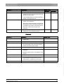
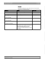
Parameters
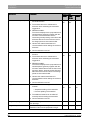
Minimal Thickness (Radial)
Description
● Set the minimum wall thickness in the
horizontal direction.
● The software tries not to fall below this
thickness when calculating the restoration
suggestions.
Default value
Crown
Inlay/
Onlay
Veneer
500µm
500µm
-
ON
ON
● DESIGN And MILL
The value is displayed on the preparation as a
semitransparent geometry together with the
minimum occlusal thickness and the
instrument geometry setting. Areas where the
thickness falls short of the minimum level in
the design phase are thus made visible.
● Observe the material manufacturer's
recommendations when setting the minimum
thickness.
● Can be switched on and off
Minimal Thickness (Occlusal)
● Set the minimum wall thickness in the occlusal 700µm
direction.
ON
● The software tries not to fall below this
thickness when calculating the restoration
suggestions.
700µm
-
ON
● DESIGN And MILL
The value is displayed on the preparation as a
semitransparent geometry together with the
minimum radial thickness and the instrument
geometry setting. Areas where the thickness
falls short of the minimum level in the design
phase are thus made visible.
● Observe the material manufacturer's
recommendations when setting the minimum
thickness.
● Can be switched on and off
Margin Thickness
● Reinforce restoration margins with additional
material.
– Simplifies handling of the restoration
50µm
50µm
50µm
ON
ON
ON
– Prevents splitting of the material
● The additional material can be milled off
manually before inserting the restoration.
● Can be switched on and off
"Margin Ramp Angle"
Specifies the angle at which the restorations rise
from the edge.
60°
60°
60°
"Margin Ramp Width"
Specifies the length of the edge with which the
restoration rises from the preparation margin.
300µm
150µm
150µm
28
63 75 914 D3534
D3534.208.03.07.02 08.2015
Sirona Dental Systems GmbH
5 Configuration
Operator's Manual inLab SW
5.1 Parameters
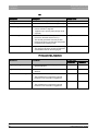
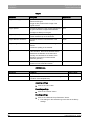
Parameters
Description
Default value
Crown
Regard Instrument Geometry
Considers the instrument geometry in the bottom YES
of the restoration.
Inlay/
Onlay
Veneer
YES
YES
YES
YES
Areas of the preparation that are smaller than the
diameter of the instrument geometry are
calculated in the bottom of the restoration so that
they increase with the instrument geometry.
Remove Undercuts
Undercuts within the preparation margin are
blocked out in the restoration bottom.
YES
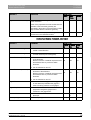
Abutment (anatomical, framework, lower layer)
Abutment parameters (anatomic, framework, bottom layer)
Description
Default value
båÖäáëÜ
Parameters
Anatomi Framew Lower
cal
ork
layer
Proximal Contacts Strength
● Determines the thickness of a contact in the
mesial or distal direction.
25µm
-
-
Occlusal Contacts Strength
● Determines the thickness of a contact in the
occlusal direction (to the antagonist).
25µm
-
-
Minimal Thickness (Radial)
● Determines the minimum radial wall thickness 500µm
of the abutment.
ON
Minimum amount of material required around
the adhesive base to produce a stable
abutment.
500µm
500µm
ON
ON
700µm
700µm
ON
ON
● Can be switched on and off
Minimal Thickness (Occlusal)
● Determines the minimum occlusal wall
700µm
thickness of the abutment.
ON
Minimum amount of material required around
the adhesive base to produce a stable
abutment.
● Can be switched on and off
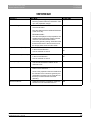
Gingival Placement Pressure
● Determines how strongly the initial suggestion 0µm
for the abutment penetrates the gingiva in
order to build up pressure on the gingiva.
0µm
-
Gingival Depth
● Determines how far below or above the
preparation margin the gingiva lies in
reference to the gingival line.
0µm
0µm
-
Shoulder Width
● Width of the shoulder of an abutment or
telescope.
-
1,000µ
m
1,000µ
m
Telescope Angle
● Telescope angle of an abutment or telescope. -
4°
4°
63 75 914 D3534
D3534.208.03.07.02
08.2015
29
5 Configuration
Sirona Dental Systems GmbH
5.1 Parameters
Operator's Manual inLab SW
Crown (framework, telescope)
Crown parameters (framework, telescope)
Parameters
Description
Default value
Framework
Telescope
Spacer
● Possibility for setting the space for the
80µm
fastening material below the restoration. Acts
up to the preparation margin. The spacer can
be set differently for radial and occlusal.
80µm
Minimal Thickness (Radial)
● Set the minimum wall thickness in the
horizontal direction.
500µm
500µm
ON
ON
● The value determines the radial wall thickness
of the crown cap.
● DESIGN And MILL
The value is displayed on the preparation as a
semitransparent geometry together with the
minimum occlusal thickness and the
instrument geometry setting. Areas where the
thickness falls short of the minimum level in
the design phase are thus made visible.
● Can be switched on and off
Minimal Thickness (Occlusal)
● Set the minimum wall thickness in the occlusal 700µm
direction.
ON
● The value determines the occlusal wall
thickness of the crown cap.
700µm
ON
● DESIGN And MILL
The value is displayed on the preparation as a
semitransparent geometry together with the
minimum radial thickness and the instrument
geometry setting. Areas where the thickness
falls short of the minimum level in the design
phase are thus made visible.
● Can be switched on and off
Margin Thickness
● Reinforce restoration margins with additional
material.
– Simplifies handling of the restoration
50µm
50µm
ON
ON
– Prevents splitting of the material
● The additional material can be milled off
manually before inserting the restoration.
● Can be switched on and off
Telescope Angle
● Angle by which the outer wall of the telescope cone is inclined inward in relation to the
restoration axis.
4°
Telescope Height
● Initial height of the outer wall of the telescope cone from the cervical shoulder to the junction
to the occlusal surface.
3000µm
● It influences the size of the friction surface.
30
63 75 914 D3534
D3534.208.03.07.02 08.2015
Sirona Dental Systems GmbH
5 Configuration
Operator's Manual inLab SW
5.1 Parameters
Parameters
Description
Occlusal Shoulder Width
● Width of the occlusal shoulder at the junction
between the outer wall of the telescope cone
and the occlusal surface.
●
Regard Instrument Geometry
Default value
Framework
Telescope
-
300µm
YES
YES
YES
YES
The occlusal shoulder is inclined inward 45° in
relation to the telescope axis.
● Considers the instrument geometry in the
bottom of the restoration.
Remove Undercuts
● Undercuts within the preparation margin are
blocked out in the restoration bottom.
båÖäáëÜ
● Areas of the preparation that are smaller than
the diameter of the instrument geometry are
calculated in the bottom of the restoration so
that they increase with the instrument
geometry.
Attachment
Attachment parameters
Parameters
Description
Default value
Attachment Diameter
● Diameter of the cylindrical anchor of the
positive part.
1500
Attachment Height
● Height of the entire positive part.
2000
Attachment Bridge Length
● Length of male bridge.
The male bridge is the connecting element
between the anchor and the base.
1000
Attachment Bridge Width
● Width of bridge.
1000
Attachment Gingiva Distance
● Distance from male bottom to gingival
adaptation.
0
● Negative values result in a penetration of the
gingiva.
Attachment Gingiva Adaption
● Gingival adaptation: Yes/No
YES
Attachment Spacer Value
● Divided attachment:
Space between positive part and cut-out
negative part in neighboring positive part.
80µm
Attachment Shoulder Width
● Size of plate located on the gingiva.
500µm
Bar parameters
63 75 914 D3534
D3534.208.03.07.02
08.2015
31
5 Configuration
Sirona Dental Systems GmbH
5.1 Parameters
Operator's Manual inLab SW
Bar
Parameters
Description
Bar Height
● Describes the height of the bar segment in µm. 3000
Bar Width
● Describes the width of the bar segment in µm. 3000
Bar Cone Angle
● Describes the angle of incidence of lateral and 4°
friction surfaces in degrees.
●
Default value
Applies only to primary bars (design mode
squared).
Bar Smoothing Radius
● Describes the radius of the junction between
the anchor element and the bar in µ.
This should guarantee a smooth junction
between the anchor and the bar and prevent
predetermined breaking points.
2500 µm
Bar Interdental Space
● Space in µm required to ensure easy cleaning. 1000 µm
This space is left in the anchor-bar transition
zone between the bar and the gingiva.
Pontic (anatomical, framework)
Pontic parameters (anatomic)
Parameters
Description
Default value
Anatomical
Framework
Gingival Spacing
● Space between pontic and preparation
geometry/gingiva.
0
0
Lingual Opening Angle
● Increase of pontic for the basal area in the oral 0
direction.
0
Proximal Contacts Strength
● Set the thickness of the proximal contacts.
25µm
-
25µm
-
● The software tries to achieve this stored
thickness in the restoration suggestions.
Occlusal Contacts Strength
● Set the thickness of the occlusal contacts.
● The software tries to achieve this stored
thickness in the restoration suggestions.
32
63 75 914 D3534
D3534.208.03.07.02 08.2015
Sirona Dental Systems GmbH
5 Configuration
Operator's Manual inLab SW
5.1 Parameters
Crown (bottom layer)
Multilayer crown parameters (bottom layer)
Parameters
Description
Default value
Spacer
● Possibility for setting the space for the
120µm
fastening material below the restoration. Acts
up to the preparation margin.
Occlusal Milling Offset
● Set the minimum wall thickness in the
horizontal direction.
0µm
● The value determines the radial wall thickness
of the crown cap.
Minimal Thickness (Radial)
● Determines the minimum radial wall thickness 500µm
in the horizontal direction.
ON
● Can be switched on and off
Minimal Thickness (Occlusal)
● Determines the minimum radial wall thickness 700µm
in the occlusal direction.
ON
● Can be switched on and off
Telescope Angle
● Angle by which the outer wall of the telescope 4°
cone is inclined inward in relation to the
restoration axis.
Regard Instrument Geometry
● Considers the instrument geometry in the
bottom of the restoration.
båÖäáëÜ
● DESIGN And MILL
The value is displayed on the preparation as a
semitransparent geometry together with the
minimum occlusal thickness and the
instrument geometry setting. Areas where the
thickness falls short of the minimum level in
the design phase are thus made visible.
YES
● Areas of the preparation that are smaller than
the diameter of the instrument geometry are
calculated in the bottom of the restoration so
that they increase with the instrument
geometry.
Remove Undercuts
● Undercuts within the preparation margin are
blocked out in the restoration bottom.
YES
Multilayer crown parameters (top layer)
63 75 914 D3534
D3534.208.03.07.02
08.2015
33
5 Configuration
Sirona Dental Systems GmbH
5.1 Parameters
Operator's Manual inLab SW
Crown (top layer)
Parameters
Description
Default value
Spacer
● Possibility for setting the space for the
120µm
fastening material below the restoration. Acts
up to the preparation margin.
Occlusal Milling Offset
● Apply or remove material in the occlusal
direction over the entire occlusal surface.
0µm
● This value concerns only the milling result.
● DESIGN and MILL
The effects are not visible.
Minimal Thickness (Radial)
● Set the minimum wall thickness in the
horizontal direction.
● The software tries to achieve this stored
thickness in the restoration suggestions.
500µm
ON
Minimal Thickness (Occlusal)
● Set the minimum wall thickness in the occlusal 700µm
direction.
ON
● The software tries to achieve this stored
thickness in the restoration suggestions.
Regard Instrument Geometry
● Considers the instrument geometry in the
bottom of the restoration.
YES
● Areas of the preparation that are smaller than
the diameter of the instrument geometry are
calculated in the bottom of the restoration so
that they increase with the instrument
geometry.
Remove Undercuts
● Undercuts within the preparation margin are
blocked out in the restoration bottom.
YES
Model
Model
Observe the information supplied concerning the pins, model holders and
base plates.
Parameters
Description
Segmentation Cut Width
● Set the width of the saw-cut.
Baseplate Distance
● Adjust the distance of the base plates from each other.
Pin Diameter
● Set the diameter of the pins.
Pin Spacing
● Set the distance of the pins from each other.
Virtual articulator
34
63 75 914 D3534
D3534.208.03.07.02 08.2015
Sirona Dental Systems GmbH
5 Configuration
Operator's Manual inLab SW
5.1 Parameters
Articulator
The preset parameters are mean values which can be used without
alteration for an average articulation.
Parameters
Setting
Mean value
"Arms"
Side of the Bonwill triangle
105mm
"Base"
Intercondylar distance
100mm
"Balkwill Angle"
Balkwill angle
23°
"Sagittal Angle Left"
Sagittal condylar path inclination
35°
Bennett angle
15°
Initial Bennett movement
0µm
Fragment table articulation parameter.
and
"Sagittal Angle Right"
"Bennett Angle Left"
and
"Immediate side shift left"
and
båÖäáëÜ
"Bennett Angle Right"
"Immediate side shift right"
"Include Restorations"
If activated, available restorations are taken into consideration for the calculation of the FGPs as
if they were already inserted. This means
reconstructed cuspid guidance can be
considered for the other restorations in the case,
for example.
Gingiva parameters
63 75 914 D3534
D3534.208.03.07.02
08.2015
35
5 Configuration
Sirona Dental Systems GmbH
5.1 Parameters
Operator's Manual inLab SW
Gingiva
Parameters
Description
Default value
"Gingiva Cleaning Spacer"
Specifies the distance between the gingival
element and the gum.
0µm
The gap is also produced at the edge of the
gingival element.
"Gingiva Spacer"
Specifies the distance of the gingival element and 50µm
the gums between the edges of the elements.
The edges are always on the gum.
"Gingiva Implant Spacer"
Specifies the space between the gingival element 100µm
and the cemented cap of the abutment.
"Gingiva Minimal Thickness"
Specifies the minimum wall thickness of the
element
"Gingiva Margin Thickness"
Specifies the material thickness at the edge of the 50µm
element.
700µm
Prevents the splitting of the material.
"Regard Instrument Geometry"
Considers the instrument geometry in the bottom
of the restoration. Areas of the element that are
smaller than the diameter of the instrument
geometry are calculated in the bottom of the
restoration so that they increase with the
instrument geometry.
Yes
"Remove Undercuts"
Undercuts within the preparation margin are
blocked out in the restoration bottom.
Yes
CEREC Guide
Fragment: CEREC Guide
Parameters
Description
Default values
Thickness
Template body thickness
4mm
Spacer
Gap between the contact surface on the remaining teeth and 60µm
the interior of the template body.
Accepting settings
Applying/discarding settings
➢ Click on the "Ok" button.
Discarding settings
➢ Click on the "Cancel" button.
Resetting settings
Resetting settings
➢ Click on the "Reset All Group Parameter" button.
The settings for this restoration type are reset to the factory
settings.
36
63 75 914 D3534
D3534.208.03.07.02 08.2015
Sirona Dental Systems GmbH
5 Configuration
Operator's Manual inLab SW
5.2 Devices
5.2 Devices
All connected devices can be displayed and configured under the menu
item "Devices" .
Devices menu item
A green check mark on a device indicates its availability.
Adding devices automatically
Adding devices (automatic)
You can add additional devices with the "Scan for New Devices" function.
✔ The unit is connected to the PC.
1. Click on the "Scan for New Devices" button.
All units connected to the PC are recognized. In the case of new
units, you will be prompted to enter a name.
2. Enter a name for the new unit.
Adding devices (manual)
You can add devices manually with the "Add Device (Manual)" function.
This is mandatory for units which cannot be operated at the maximum
speed of 115,200 baud. This concerns devices with long cable
connections or when certain radio modules (e.g. Futaba, 19,200 baud)
are used.
1. Click on the "Add Device (Manual)" button.
2. Choose whether the device should be connected via the network or
a serial connection.
3. Network: Enter the network address.
Serial: Enter the COM port and the baud rate.
4. Click on the "Ok" button.
The software attempts to contact the device.
If the connection fails, check the connection. If necessary, ask a qualified
technician.
Updating
Updating CEREC SW 4
With the "Refresh Devices" button you can
● Refresh the status display; e.g. check whether a milling unit has
finished milling in the meantime, or
● Check the current availability of a device.
63 75 914 D3534
D3534.208.03.07.02
08.2015
37
båÖäáëÜ
Adding devices (manual)
5 Configuration
Sirona Dental Systems GmbH
5.2 Devices
Operator's Manual inLab SW
5.2.1
inEos X5
Under the "inEos X5" menu item, the inEos X5 can be set.
General
Setting
Description
Shake tolerance
● Set motion sensitivity for automatic
activation.
Settings
● The more exact the setting, the longer
you have to hold the model still before
taking the next scan.
Acquisition behaviour
● Setting scan behavior during the range
scan
● If the setting is activated, the standard
scan sequence is initiated while you
select the detail areas.
Accepting settings
Applying/discarding settings
➢ Click on the "Ok" button.
Discarding settings
➢ Click on the "Cancel" button.
5.2.1.1
Resetting settings
➢ Click on the "Reset inEos X5 Settings" button.
The settings are reset to factory settings.
5.2.1.2
Calibration
✔ The inLab SW is switched on.
✔ The jaw model supplied for calibration is ready.
✔ You have restarted the software.
Procedure
1. Click the "Configuration" button in the menu.
2. Click the "Devices" button.
3. Click "inLab SW" .
A selection menu opens.
4. Click on the "Calibrate" button.
The calibration dialog opens.
5. Follow the steps in the calibration dialog.
6. Position the calibration model on the rotation disk in such a way that
the front teeth are facing directly in the direction of the unit.
7. Start the scan process.
The unit is calibrated. Wait until the process has been completed.
8. Restart the software.
38
63 75 914 D3534
D3534.208.03.07.02 08.2015
Sirona Dental Systems GmbH
5 Configuration
Operator's Manual inLab SW
5.2 Devices
5.2.2
inEos Blue
Under the menu item "inEos Blue" , inEos Blue can be set.
Setting
Description
Shake tolerance
● Set motion sensitivity for automatic
activation.
● The more exact the setting, the longer
you have to hold the model still before
taking the next scan.
Accepting settings
Applying/discarding settings
➢ Click on the "Ok" button.
Discarding settings
5.2.2.1
båÖäáëÜ
➢ Click on the "Cancel" button.
Resetting settings
➢ Click on the "Reset inEos Blue Settings" button.
The settings are reset to factory settings.
5.2.2.2
Calibration
1. Click on the "Calibrate" button.
2. Then simply proceed as prompted by the software.
Also observe the operating instructions of the inEos Blue.
5.2.2.3
XYZ calibration
1. Click on the "Calibrate XYZ" button.
2. Then simply proceed as prompted by the software.
Also observe the operating instructions of the inEos Blue.
63 75 914 D3534
D3534.208.03.07.02
08.2015
39
5 Configuration
Sirona Dental Systems GmbH
5.2 Devices
Operator's Manual inLab SW
5.2.3
5.2.3.1
Milling unit
Editing settings
inLab MC XL
inLab MC XL
You can later edit the following settings via the menu item "MC XL" :
● Name
● Connection settings
– Retrieve IP settings automatically
– Specify IP settings manually
● Manual block fixing
– If you use manual block fixing, a check mark must be placed in
front of "Manual block fixation" .
– Models can only be milled using manual block fixation.
● Second motor set
– The check mark must be placed in front of "Two Bur Sets" .
– You can deactivate instrument sets individually. A deactivated
instrument set will simply be ignored during production,
calibration etc.
NOTICE! The restoration may be damaged if longer instruments
are present in the deactivated instrument set than in the active
set. Ensure that the instruments installed in the deactivated
instrument set are not longer than those in the active set.
● Scanner
– If the grinding unit has an integrated scanner, a check mark must
be placed in front of "Scanner" .
– Use the scanner to read bar codes.
● Bar code reader
– If a bar code reader is used, this option must be activated.
● External tank
– If the external water tank is connected and the check mark has
been placed, you will not be reminded to change the water until
a later point in time.
● Firmware Update
– Click on the "Firmware Update" button to load the firmware
related to the software on the MC XL.
inLab
40
63 75 914 D3534
D3534.208.03.07.02 08.2015
Sirona Dental Systems GmbH
5 Configuration
Operator's Manual inLab SW
5.3 Settings
inLab
You can later edit the following settings via the menu item "CEREC 3/
inLab" :
● Name
● Connection settings
● Scanner
- If the "CEREC 3/inLab" milling unit has an integrated scanner
(option, Order No. 58 33 707) a check mark must be placed in front
of "Scanner" .
- If a scanner is retrofitted, your service engineer must place a check
mark in front of "Scanner" .
5.2.3.2
Calibration
1. Click on the "Calibrate" button.
2. Then simply proceed as prompted by the software.
5.2.3.3
Changing instruments
1. Click on the "Change Instruments" button.
2. Then simply proceed as prompted by the software.
5.2.3.4
Removing the milling unit
1. Click on the "Delete Device" button.
2. Then simply proceed as prompted by the software.
5.3 Settings
The menu item "Settings" has the following subitems:
General
● "ADA/FDI Notation"
Fragment inLab SW settings
● "Warning messages"
● "Order Database"
● "Language"
● "MC XL Milling"
● "Material"
● "generic machines"
5.3.1
ADA/FDI odontogram
You can set the odontogram using "ADA/FDI Notation" :
● International ("FDI Notation" )
● USA ("ADA Notation" )
63 75 914 D3534
D3534.208.03.07.02
08.2015
41
båÖäáëÜ
● Large water tank
- If the 25-liter canister (option, Order No. 60 56 217) is connected
and the check mark has been placed, you will not be reminded to
change the water until a later point in time.
- If the 25-liter canister is retrofitted, your service engineer must place
a check mark in the box in front of "Large Water Tank" .
5 Configuration
Sirona Dental Systems GmbH
5.3 Settings
Operator's Manual inLab SW
5.3.2
Warning messages
Warnings may appear in pop-up windows when using the software. Many
of these messages can be deactivated by clicking on the "Don't show this
message again" check box. If this check box is already selected or if a
new user uses the software, all warnings can be reset here. All warnings
are then displayed, if required.
Information on warnings
5.3.3
Setting
Description
YES
Displays all the deactivated warnings in the workflow
again.
NO
Warnings which were previously hidden, remain hidden.
Job database
In the menu item "Order Database" , you can determine where patient
data and cases are saved and to which path the workpiece database
should be stored.
To change the directory for one of the databases, click on "Browse" and
select the desired path.
You can place databases on a network path so that other PCs can also
access this data and can secure them centrally.
5.3.4
Language
Here, you can set the language of the software.
From software version inLab SW 4.x, a restart of the application is no
longer required in order to switch language.
5.3.5
MC XL milling
You can activate and deactivate the grinding manufacturing option for
zirconium oxide, plastic, and metal here.
When this option is activated, you can choose between the milling and
grinding manufacturing processes for plastic, metallic and zirconium
oxide materials in the material selection step.
Grinding of zirconium oxide, plastic and metal is possible using machines
with the following serial numbers:
Machine type
Serial number
inLab MC XL
129001
CEREC MC XL
129001
CEREC MC XL Premium Package
302001
CEREC MC
202001
CEREC MC X
231001
Fragment table Milling inLab MC XL+CEREC MC XL 300000
Other machines must be equipped with the milling starter kit, Design 2011
(REF: 64 48 893) or with the milling starter kit for connected motors (REF:
64 51 079).
42
63 75 914 D3534
D3534.208.03.07.02 08.2015
Sirona Dental Systems GmbH
5 Configuration
Operator's Manual inLab SW
5.4 Generic machine
5.3.6
Material configuration
You can configure the display of the materials in the software with this
setting. You can deactivate either a whole manufacturer, individual
materials of a manufacturer, or block sizes.
➢ To do this, remove the tick next to the relevant display.
Manufacturer, material, or block size is no longer displayed in the
selection lists.
5.4 Generic machine
If you wish to establish restorations for other production machines, you
can enter the necessary parameters of this machine here.
Tip: You can configure several production machines.
You can assign an individual name to the machine.
båÖäáëÜ
Under "Machine Properties" , you can set the following:
● The number of axes (3, 4 or 5-axis)
● The smallest grinding diameter
● The type of grinding head (cylinder, ball-shaped)
You can select the data path where the data should be saved.
63 75 914 D3534
D3534.208.03.07.02
08.2015
43
6 Restoration types and design mode
Sirona Dental Systems GmbH
6.1 Restoration types
Operator's Manual inLab SW
6
Restoration types and design mode
6.1 Restoration types
Single tooth restoration
Single tooth restoration
Symbol
Restoration type
Design mode
Crown
● Biogeneric Individual
(Split: MultiLayer)
● Framework
● Biogeneric Copy
(Split: MultiLayer)
● Biogeneric Reference
(Split: MultiLayer)
● Telescope
Inlay/Onlay
● Biogeneric Individual
● Biogeneric Copy
Veneer
● Biogeneric Individual
● Biogeneric Copy
● Biogeneric Reference
Implant
Superstructure
● Biogeneric Individual
(Split: MultiLayer)
● Framework
● Biogeneric Copy
(Split: MultiLayer)
● Biogeneric Reference
(Split: MultiLayer)
Missing
44
Click on the teeth in the
odontogram which are not
created.
63 75 914 D3534
D3534.208.03.07.02 08.2015
Sirona Dental Systems GmbH
6 Restoration types and design mode
Operator's Manual inLab SW
6.1 Restoration types
Bridge restoration
Bridge restoration
Symbol
Restoration type
Design mode
Crown
● Biogeneric Individual
● Framework
● Biogeneric Copy
● Biogeneric Reference
● Telescope
Inlay/Onlay
● Biogeneric Individual
Veneer
båÖäáëÜ
● Biogeneric Copy
● Biogeneric Individual
● Biogeneric Copy
● Biogeneric Reference
Pontic
● Biogeneric Individual
(Split: MultiLayer)
● Framework
● Biogeneric Copy
(Split: MultiLayer)
● Biogeneric Reference
(Split: MultiLayer)
Missing
Click on the teeth in the
odontogram which are not
created.
Connector
● Intersection
● Anatomic
63 75 914 D3534
D3534.208.03.07.02
08.2015
45
6 Restoration types and design mode
Sirona Dental Systems GmbH
6.2 Design mode
Operator's Manual inLab SW
Symbol
Restoration type
Design mode
Bar
● Cylindric
● Squared
● Dolder
● Hader
Attachment
● Cylindric
Restoration type
Design mode
Model
Model
Symbol
Model
6.2 Design mode
Biogeneric Individual
Biogeneric Individual design mode
For more information, refer to “Biogeneric Individual [ → 48]”.
Biogeneric Reference design mode
Biogeneric Reference
For more information, refer to "Biogeneric Reference [ → 49]”.
Biogeneric Copy design mode
Biogeneric Copy
For more information, refer to “Biogeneric Copy [ → 49]”.
Anatomic / Intersection design mode
46
63 75 914 D3534
D3534.208.03.07.02 08.2015
Sirona Dental Systems GmbH
6 Restoration types and design mode
Operator's Manual inLab SW
6.2 Design mode
Anatomic / Intersection
The "Anatomic" and "Intersection" modes are available only for bridge
connectors.
Anatomic
The connector is a separate element and can be edited.
Intersection
The connector is created by penetrating the neighboring teeth. It is not a
separate element, and therefore cannot be edited.
Framework
Select this design technique to create frameworks or primary sections
without taking the antagonist information into account. These frameworks
are then not automatically suggested to support cusps.
Telescope design mode
Telescope
Select the "Telescope" design technique to set telescope elements for
bridges. The telescope elements of a bridge are always aligned parallel.
Bars design mode
Bars
You can select the following geometries for the bars:
Cylindric
Squared
Dolder
Hader
Multilayer
Multilayer design mode
However, the fully anatomical shape is broken down into a framework
with no undercut and the covering layer by this technique. The two parts
can be milled from different materials.
Do not use this design technique if you want to manually veneer a
framework.
63 75 914 D3534
D3534.208.03.07.02
08.2015
47
båÖäáëÜ
Framework design mode
6 Restoration types and design mode
Sirona Dental Systems GmbH
6.3 Biogenerics
Operator's Manual inLab SW
Gingiva
Gingival Element design mode
Select this option if you also want to construct an additional gum element
for the implant-supported bridges and bars. It represents an independent
element for which the design tools can be used.
The "Gingiva" option is currently only available for the design of implantsupported restorations.
6.3 Biogenerics
6.3.1
General information on biogenerics
Biogenerics enable the inLab SW software to reconstruct teeth in a
natural way. Biogenerics is a biogeneric process based on the scientific
understanding that there are morphological connections between the
teeth that can be expressed in mathematical functions.
With inLab SW 4.x software, the suggestion process for biogenerics has
experienced fundamental revision: now the positioning and the entire
morphology are also included in the analysis and suggestion.
Consequently, the quality of the initial suggestions has been significantly
further improved. This applies to individual teeth, but especially for large
bridges, multiple restorations and anterior teeth as well.
All scanned teeth are analyzed with respect to their position and
morphology. Based on this analysis the relevant restoration can be
produced in fully automated fashion.
For the biogenerics to deliver ideal suggestions, it is important that entries
are correct and complete. This applies to the following steps in particular:
● Exposure
The exposure should always include the entire model, where
possible. This applies in particular to large bridges and multiple
restorations. Data holes around the preparation and the proximal
contacts should be avoided.
● Model axis
The model axis should be aligned precisely (see “Set model axis”).
6.3.2
Biogeneric Individual
In the "Biogeneric Individual" design technique, the exposure taken is
analyzed and the restoration suggestion is calculated on the basis of this
information. The more information that is available, the more successful
the calculation. A full image of at least one neighboring tooth should
therefore be taken from the occlusal/incisal direction. For anterior and
corner teeth, an image of the labial surface should also be taken.
For premolars or molars, the calculation is mainly based on the distal
neighbor, for anterior teeth the mesial neighbor is used.
48
63 75 914 D3534
D3534.208.03.07.02 08.2015
Sirona Dental Systems GmbH
6 Restoration types and design mode
Operator's Manual inLab SW
6.3 Biogenerics
6.3.3
Biogeneric Copy
Select the "Biogeneric Copy" design technique to transfer parts of an
existing occlusal surface to the restoration and enhance the rest using the
patented Biogeneric technique.
To do this, acquire the status separately in the "BioCopy Upper" or
"BioCopy Lower" image field prior to the preparation.
This technique can be used for inlays, onlays, partial crowns, crowns, and
bridges.
Biogeneric Reference
Select the "Biogeneric Reference" design technique for user definition of
the tooth to be used as a reference for calculating the restoration
suggestion. The reference tooth can be any tooth of the same class
(anterior/posterior tooth), e.g. the antagonist or the contralateral tooth.
You also can use a reference tooth from a model to achieve the desired
morphology.
This reference tooth must be acquired on a separate basis in the "BioRef
Lower" or "BioRef Upper" image field. This technique can be used for
inlays, onlays, partial crowns, crowns, and bridges.
63 75 914 D3534
D3534.208.03.07.02
08.2015
49
båÖäáëÜ
6.3.4
7 Editing orders
Sirona Dental Systems GmbH
7.1 Tools and functions of the page palette
Operator's Manual inLab SW
7
Editing orders
The section Shortcut keys [ → 155] describes how the following tools and
options can be opened via shortcut keys.
7.1 Tools and functions of the page palette
The page palette offers you various different functions, depending on the
current step.
7.1.1
View options
Different views are available to you in the "View Options" page palette.
These view options are split into global and local views. The global views
are based on the model axis of the upper and lower jaw.
Tip: You can adjust the global model axis in the "Set Model Axis" step.
Local/Global CEREC + inLab
The local views are determined by the element currently selected in the
object bar. Each element in the object bar therefore has its own
coordinate system. Depending on the current step, the following views
are available to you:
Global views
Global
● "Top"
● "Bottom"
● "Right"
● "Left"
● "Front"
● "Back side"
Local views
Local
● "Mesial"
● "Distal"
● "Buccal" / "Labial"
● "Lingual"
● "Cervical"
● "Occlusal" / "Incisal"
Enlarge or reduce the view
50
63 75 914 D3534
D3534.208.03.07.02 08.2015
Sirona Dental Systems GmbH
7 Editing orders
Operator's Manual inLab SW
7.1 Tools and functions of the page palette
Enlarge or reduce 3D preview
In the "View Options" page palette on global and local views you will find
the zoom options.
Fragment: CERERC + inLab
Using the slide you can enlarge or reduce the 3D preview.
In the attendant text field, the current degree of enlargement is displayed
in percent. Here you can also manually enter a value from 0 to 100
percent and confirm with the Enter button.
Tip: If the mouse pointer is inside the 3D preview, then you can also
change the view with the center mouse button pressed down while
simultaneously moving the mouse up and down.
Zoom adjustment via the mouse’s scroll wheel is also supported.
7.1.2
Tools
Tip: Automatic tooth change is possible when using the tools for several
restorations. You do not have to make a selection via the restoration
selector or by double-clicking.
Tools which can be used on the active restoration element are always
active. The other tools are grayed out.
The most important tools are also offered to you in the tool wheel. You
can find further information on the tool wheel in the section “Tool
wheel [ → 64]”.
You will find all tools as a sub-menu under "Tools" . The available tools
are displayed for each step.
To change a tool, click on the button of another tool in the left column of
the page palette.
To close a tool, click on the button of the active tool once more in the left
column.
Undoing and resetting
Using the "Undo" button in the tools, you can undo the last change.
Undo and reset
With the "Reset" button in the tools you can reset changes that were
made with the tool.
63 75 914 D3534
D3534.208.03.07.02
08.2015
51
båÖäáëÜ
Fragment automatic tooth change + locking
7 Editing orders
Sirona Dental Systems GmbH
7.1 Tools and functions of the page palette
7.1.2.1
Operator's Manual inLab SW
Buccal registration
Correcting buccal images
Move buccal inLab
The buccal registration takes place automatically. If it is not correct you
can do it manually.
1. Click on the "Reset" button.
The buccal registration is triggered and you have both jaws and
the buccal exposure separated on the screen.
2. Click on the buccal image and displace it to the same region on the
upper or lower jaw.
The image is accepted.
Tip: If an image is not accepted, align the jaw buccally. This
enables better overlaying.
If registration is still not possible, check whether the buccal
sections in the jaws and in the buccal image are sufficient.
3.
If the image was accepted, move the image to the corresponding
region of the opposite jaw.
Flip Buccal Impression
Flip buccal
With the "Flip Buccal Impression" function, you can rotate the buccal
image.
1. Click on the "Buccal" button.
2. Click on the "Flip Buccal Impression" button.
The buccal image is then rotated.
7.1.2.2
Buccal bite tools
You can adjust the occlusion using the following tools.
Fragment not required for CEREC
Move jaw
You can correct the buccal bite by positioning and rotating the upper jaw
using the "Align Jaw" function.
➢ Click on the "Align Jaw" button.
The rotating/positioning tool will be shown.
7.1.2.3
Shaping
With the "Form" function, you can do the following with material
● apply
● remove
● smoothen
Tip: If one of the shape tools is active, you can also switch to the following
order using the space bar on the keyboard:
Apply > Remove > Smooth > Apply > etc.
Space bar tip
52
63 75 914 D3534
D3534.208.03.07.02 08.2015
Sirona Dental Systems GmbH
7 Editing orders
Operator's Manual inLab SW
7.1 Tools and functions of the page palette
Apply material
Apply material
1. Click the "Form" button.
2. Click on the "Add" button.
3. Click with the mouse cursor on the area you wish to shape.
4. Press and hold the left mouse button and apply the material to the
surface location by moving the mouse.
Removing material
Removing material
1. Click the "Form" button.
2. Click the "Remove" button.
3. Press and hold the left mouse button and remove the material from
the surface location by moving the mouse.
Smoothing
When smoothing, you are able to smooth the surface locally.
1. Click the "Form" button.
2. Click the "Smooth" button.
3. Click with the mouse cursor on the location you wish to smoothen.
4. Press and hold the left mouse button and smoothen the surface
location by moving the mouse.
7.1.2.3.1
Properties
Modifying the size
Resizing
You can use the "Size" slider to modify the size of the area affected. The
area affected is shown as an orange-colored area on the current
restoration in the 3D preview.
The size of the area affected can be modified for each shaping tool.
1. Click the "Size" slider and press and hold the mouse button.
2. Now drag the slider to the right or left to enlarge or reduce the area
affected.
The orange-colored area (area affected) will be expanded or
reduced in the 3D preview.
Tip: You can also change the size of the area affected by dragging the
mouse up or down with the right mouse button held down on the
restoration.
Adjusting thicknesses
Fragment Adjusting thicknesses
You can use the "Strength" slider to modify the intensity of the area
affected. The thicknesses of the affected area can be modified for each
forming tool.
1. Click the "Strength" slider and press and hold the mouse button.
2. Now drag the slider to the right or left to increase or reduce the
intensity.
Hiding the neighboring restoration
Hiding the neighboring restoration
You can hide the neighboring restoration with the "Hide Neighbors"
function.
63 75 914 D3534
D3534.208.03.07.02
08.2015
53
båÖäáëÜ
Smoothing
7 Editing orders
Sirona Dental Systems GmbH
7.1 Tools and functions of the page palette
Operator's Manual inLab SW
"Apply global"
Fragment Forms for entire bridges
This function allows you to use the tool on two adjacent restorations
simultaneously. For this to happen, the teeth must be grouped in advance
(Ctrl/Shift key + left mouse button) and the check box should
subsequently be checked.
7.1.2.4
Cut out model areas
With the "Cut" function, you can cut out model areas. The cut out model
areas are then discarded. You cannot display cut out areas later on.
Cutting with CEREC SW 4
Removing the model area
The "Discard Part" function enables model areas to be removed.
Activity
When performing this activity, be careful not to accidentally cut out any
areas that e.g. are located behind the model or are otherwise cut away
from the line.
1. Click the "Cut" button.
2. Begin the cut line with a double-click.
3. Click to set additional points.
4. Finish the cut by double clicking.
The model area is cut off.
Inverting the model area
With the "Invert Selected" function, the model area that is cut out can be
inverted.
✔ The "Cut" tool is selected.
✔ You have created a cut.
➢ Click the "Invert Selected" button.
The model area which was cut out is displayed.
The rest of the model area is hidden.
Tip: You can invert the model area that is cut out by double-clicking on
the semitransparent cut-out area.
54
63 75 914 D3534
D3534.208.03.07.02 08.2015
Sirona Dental Systems GmbH
7 Editing orders
Operator's Manual inLab SW
7.1 Tools and functions of the page palette
7.1.2.5
Correcting defects
With the "Replace" function, you can correct defects and artifacts on the
model (e.g. holes or elevations).
To do so, drag a line around the defect in your model and select the
appropriate function.
1. Click the "Replace" button.
2. Set the starting point with a double-click.
3. Click to set further points in order to enclose the defect tightly. The
line must be located completely on the model.
4. Set the line end by double-clicking.
The line is finalized.
Tip: You can use delete to remove the line.
båÖäáëÜ
5. Click on the "Apply" button.
Tip: The tool can also be triggered by pressing the Enter key.
The software smoothens everything within the line by
interpolation.
7.1.2.6
Resetting the model
With the "Reset Model" function, all changes will be reset.
1. Click the "Tools" button.
2. Click on the "Reset Model" button.
The program will ask whether you really want to reset all
changes.
3. Confirm with "Ok" .
7.1.2.7
Trimming
With the "Trim" function, you can isolate the preparation. You can thus
e.g. draw in the preparation margin more easily. Trimmed image regions
can be optionally displayed and hidden later on.
General
Hiding image regions
Remove part
The "Discard Part" function enables you to hide image regions.
The trim line can also be placed over the preparation line. Only the region
underneath the preparation will then be hidden automatically. The
prepared region remains fully intact.
1. Click on the "Trim" button.
2. Click on the "Discard Part" button.
3. Start by double-clicking in the vicinity of the model or on the model.
4. Click to set additional points. Draw the line close to the preparation
around which you want to trim.
5. Finish the line by double clicking.
The smaller region of the model is hidden.
Invert selected
63 75 914 D3534
D3534.208.03.07.02
08.2015
55
7 Editing orders
Sirona Dental Systems GmbH
7.1 Tools and functions of the page palette
Operator's Manual inLab SW
Inverting an image region
With the "Invert Selected" function, an image region which was hidden
can be restored.
✔ An image region has been hidden using the "Trim" tool.
➢ Click on the "Invert Selected" button.
The hidden image region will be shown.
The image region shown will be hidden.
Tip: You can invert the hidden image area by double-clicking on the
semitransparent hidden region.
7.1.2.8
Entering the preparation margin
More information on using this tool can be found in the section “Entering
the preparation margin [ → 111]”.
General
Automatic edge detection
Automatic edge detection
With "Margin" / "Auto" , you can work with automatic edge detection.
1. Click on the "Margin" button.
2. Click on the "Auto" button.
Automatic edge detection is switched on.
Manual drawing
Interpolating technique
With "Manual" you can draw in the preparation margin manually. With
this technique, you must place the individual points close together in
order to clearly define the contour of the preparation margin even in
difficult situations.
✔ The "Margin" tool is open.
➢ Click on the "Manual" button.
The manual technique is switched on.
Manual drawing with intensity image
Interpolating technique with intensity image
With "Manual with intensity image" you can manually draw in the
preparation margin on the intensity image.
✔ The "Margin" tool is open.
➢ Click on the "Manual with intensity image" button.
The manual technique with intensity image is switched on.
Tip: As long as the "Margin" tool is activated, you can switch back and
forth between the drawing options by pressing the space bar.
7.1.2.9
Entering the baseline on the gingival mask
In the "Click Scanbody" step, you can select whether or not the gingival
mask is to be used for calculating the emergence profile. This option is
available only if a gingival mask was acquired in the "SCAN" phase.
Fragment inLab SW
The baseline for the pontic can also be entered on the gingival mask. To
do so, the corresponding option must be activated in the tool.
56
63 75 914 D3534
D3534.208.03.07.02 08.2015
Sirona Dental Systems GmbH
7 Editing orders
Operator's Manual inLab SW
7.1 Tools and functions of the page palette
7.1.2.10
Positioning
With the "Move" function, you can displace, rotate, and scale the
restoration.
Displacing and rotating
Displacing and rotating
With the "Position and Rotate" tool, you can displace and rotate the
restoration.
Displacing and rotating the restoration
➢ Left-click on an arrow symbol and hold the button down.
You can displace or rotate the restoration in the corresponding
direction.
➢ Right-click on an arrow symbol and hold the button down.
You can change the axis on which the object is rotated or moved.
Scaling
63 75 914 D3534
D3534.208.03.07.02
08.2015
57
båÖäáëÜ
Changing axes
7 Editing orders
Sirona Dental Systems GmbH
7.1 Tools and functions of the page palette
Operator's Manual inLab SW
Scaling
With the "Scale" function, you can change the size of the restoration. The
area affected is shown as an orange-colored area.
1. Click on the "Move" button.
2. Click on the "Scale" button.
3. Use the mouse cursor to click with the arrow on the selected scaling
direction.
The arrow is shown in orange.
4. Hold the left mouse button down and drag the mouse to enlarge or
reduce the restoration.
The orange-colored area will be expanded or reduced.
Layout
Effect
Click on the ball in the center to enlarge or reduce
the entire restoration.
Drag the mouse and click on the arrow to enlarge
or reduce the restoration in the mesio-distal
direction.
Drag the mouse and click on the arrow to enlarge
or reduce the restoration in the bucco-lingual
direction.
Drag the mouse and click on the arrow to enlarge
or reduce the restoration in the direction shown.
The restoration is enlarged or reduced to half-page
size.
7.1.2.11
Recalculating restorations
The initial suggestion can be recalculated using the "Recalculate" tool.
1. To do so, select "Recalculate" and then click on "Recalculate" in the
tool.
2. If you select the "Unadapted" option, you can choose to align the
restoration before the recalculation via the "Move" / "Scale" tool.
3. Finally, click on "Recalculate" to conclude the process.
58
63 75 914 D3534
D3534.208.03.07.02 08.2015
Sirona Dental Systems GmbH
7 Editing orders
Operator's Manual inLab SW
7.1 Tools and functions of the page palette
7.1.2.12
Designing
Anatomical
Anatomical
The "Anatomic" function is used to preselect regions of morphology, e.g.
cusps or fissure lines, for designing.
Circular
Circular
The "Circular" is used to preselect a circular region for designing.
Fragment: General shape from CEREC SW 4.4
You can shape the restoration in 2 ways:
7.1.2.12.1
Function
Description
2-Direction
The movement is possible along one axis orthogonal
to the restoration surface.
4-Direction
The movement is possible along two axes parallel to
the restoration surface.
Properties
Changing size
This option is available only for the circular variant.
Modifying the size
You can use the "Size" slider to modify the size of the area affected. The
area affected is shown as an orange-colored area on the current
restoration in the 3D preview.
1. Click the "Size" slider and press and hold the mouse button.
2. Now drag the slider to the right or left to enlarge or reduce the area
affected.
The orange-colored area (area affected) will be expanded or
reduced in the 3D preview.
Tip: You can also change the size of the area affected by dragging the
mouse up or down with the right mouse button held down on the
restoration.
Hiding the neighboring restoration
Hiding the neighboring restoration
You can hide the neighboring restoration with the "Hide Neighbors"
function.
63 75 914 D3534
D3534.208.03.07.02
08.2015
59
båÖäáëÜ
The "Shape" function enables you to shape a selected region.
7 Editing orders
Sirona Dental Systems GmbH
7.1 Tools and functions of the page palette
7.1.2.13
Operator's Manual inLab SW
Biogeneric variation
Phase "DESIGN" – Step "Edit Restoration"
With the "Biogeneric Variation" function, you can generate different
variants of the possible morphology.
1. Click the "Biogeneric Variation" slider and press and hold the mouse
button.
2. Drag the slider to the left or right.
The new morphology is shown as a 3D preview.
3. If you are satisfied with the morphology, release the mouse button.
The new morphology is applied to the current restoration.
7.1.2.14
Reduce
With the "Reduce" function, you can anatomically reduce the restoration:
You also can perform partial reductions.
7.1.2.14.1
Full reduction
1. Click on the "Reduce" button.
2. Set the reduction level using the slider. The value will be memorized
for other reductions.
3. Click on "Apply" to execute the reduction.
The restoration is reduced by the set value.
Tip: You can reduce several teeth at the same time by grouping them first
with the following key combinations:
● "Ctrl" + left mouse button
● Shift key + left mouse button
Tip: You can edit the reduction line before the reduction and create
festoons and back rest plates quickly and easily.
60
63 75 914 D3534
D3534.208.03.07.02 08.2015
Sirona Dental Systems GmbH
7 Editing orders
Operator's Manual inLab SW
7.1 Tools and functions of the page palette
7.1.2.14.2
Partial reduction
1. Click on the "Reduce" button.
2. Double-click on the restoration and draw a closed line.
3. Set the reduction level using the slider.
4. Click on "Apply" to execute the reduction.
The restoration is reduced by the set value.
Tip: You can use the space bar or "Toggle area" to switch the area to be
reduced. It is displayed as an orange colored area.
7.1.2.14.3
Properties
Taking into account the minimum geometry during reductions
● If the corresponding option is selected in the tool, the minimum
geometry is observed during reduction.
● If the corresponding option is not selected in the tool, the minimum
geometry may not be reached during reduction.
Attaching the base of the pontic
Attaching the base of the pontic
If the "Stick Pontic Base to Gingiva" function is active, the base of the
pontic is not reduced for a full reduction.
Hiding the neighboring restoration
Hiding the neighboring restoration
You can hide the neighboring restoration with the "Hide Neighbors"
function.
7.1.2.15
Contacts
If you modify the restoration, the contact surfaces also will be displaced.
The "Contacts" function is used to reset the contacts to the thickness set
in the parameters.
1. Click on the "Contacts" button.
2. Click the "Mesial" , "Distal" , "Occlusal" , or "FGP" button.
The respective contact surface is then reset.
Hiding the neighboring restoration
Hiding the neighboring restoration
You can hide the neighboring restoration with the "Hide Neighbors"
function.
7.1.2.16
Adjusting sprue location
This option is only available for the PRODUCE manufacturing process.
Only for the PRODUCTION manufacturing process
The "Sprue" function enables you to rotate the position of the sprue
location on the restoration in 2 ways:
● Step-by-step, by clicking on the arrow in the circle segment.
● Continuously, by clicking and holding the left mouse button inside the
circle segment and moving the mouse.
63 75 914 D3534
D3534.208.03.07.02
08.2015
61
båÖäáëÜ
The "Reduce" tool enables you to choose whether the minimum
geometry should be taken into account during reductions.
7 Editing orders
Sirona Dental Systems GmbH
7.1 Tools and functions of the page palette
7.1.2.17
Operator's Manual inLab SW
Positioning blocks
Moving
Moving
The "Position" function enables you to displace the block surrounding the
restoration in all spatial directions until the restoration strikes one of the
block margins.
You can move the block in 3 ways:
● Step-by-step, by clicking on one of the arrows showing the movement
axes on the semitransparent cube.
● Continuously in 2 directions, by clicking on one side of one of the
cube surfaces, holding the button down and moving the mouse.
● Continuously in all 4 directions, by clicking in the center of a cube
surface, holding the button down and moving the mouse.
Rotating
Rotating
With the "Rotate" function, you can rotate the restoration about the axis
of the block.
This function is only available for the "MILL" manufacturing process.
You can rotate the restoration in the block in 2 ways:
● Step-by-step, by clicking on the arrow in the circle segment.
● Continuously, by left-clicking on or inside of the circle segment and
moving the mouse.
7.1.2.18
Incisal variation
Phase "DESIGN" – Step "Edit Restoration"
Using the "Incisal Variation" function, you can generate mamelons
(vertical structures) and growth lines (horizontal structures) on your
anterior restorations.
Strength
Using the "Strength" slider you can set the intensity at which the selected
structure acts on a restoration.
Variation
Using the "Variation" slider you can select the desired structure type.
● Items 1 to 4 stand for mamelons (vertical structures).
● Items 5 to 6 stand for growth lines (horizontal structures).
Positioning structures
If you have set the structure type and the desired intensity, you can now
adjust the position of the structure.
1. To do this click on your current anterior restoration in the 3D preview
and then hold down the left mouse button.
The tools effect area is colored in orange.
2. Now move the mouse to position the structure as you want it.
62
63 75 914 D3534
D3534.208.03.07.02 08.2015
Sirona Dental Systems GmbH
7 Editing orders
Operator's Manual inLab SW
7.1 Tools and functions of the page palette
Applying structures
1. If you are satisfied with the structure created, click on the "Apply"
button. The created structure is now saved.
IMPORTANT
In order to combine multiple structures together, first complete a
structure and then save this with the "Apply" button.
2. Now create additional structures and save every other structure here
once they are completed.
7.1.2.19
Using a gingival mask
In the "Click Scanbody" step, you can select whether or not the gingival
mask is to be used for calculating the emergence profile. This option is
available only if a gingival mask was acquired in the "SCAN" phase.
The baseline for the pontic can also be entered on the gingival mask. To
do so, the corresponding option must be activated in the tool.
7.1.2.20
Splitting
Phase "DESIGN" – Step "Edit Restoration"
Using the "Split" function you can split a full-format "Multilayer Abutment"
into a frame and veneer structure.
Using the "Unsplit" function you can join the frame and a veneer structure
of a multi-layer abutment back together.
1. Select the desired option "Split" or "Unsplit" through the associated
button.
2. Then click on the "Apply" button.
The multi-layer abutment is split or joined together again.
7.1.2.21
Scaling
You can use this tool for frameworks, telescopes, multilayer frameworks
and bars.
In the tool menu, you can select whether the tool is to be effective in the
radial or the occlusal direction. You can toggle between these directions
with the space bar or with the mouse.
1. Place the mouse pointer on an active restoration.
Various design elements are then offered, depending on the
restoration type.
An arrow shows the direction in which the scaling will occur. The
area affected is shown highlighted in orange.
2. Press and hold down the left mouse button.
3. Move the mouse to change the object.
63 75 914 D3534
D3534.208.03.07.02
08.2015
63
båÖäáëÜ
Fragment inLab SW
7 Editing orders
Sirona Dental Systems GmbH
7.1 Tools and functions of the page palette
Operator's Manual inLab SW
Radial/occlusal
Radial/occlusal
You can edit the edge of the crown caps and bridge frameworks for the
restoration type "Framework" in radial or occlusal direction.
1. Click the "Scale" button.
2. Click on the "Radial" or "Occlusal" button.
3. Place the mouse pointer on an active restoration.
The area affected is shown highlighted in orange.
4. Press and hold down the left mouse button.
5. Move the mouse to change the object.
Properties
Modifying the size
If a check mark is placed in front of "Complete" the area affected is
maximized and applies to the entire design element. If no check mark is
placed, you can determine the area affected individually.
You can use the "Size" button to modify the size of the area affected. The
area affected is shown as an orange colored area. The size of the area
affected can be modified for each shaping tool.
1. Click the "Scale" button.
2. Click the "Size" button and press and hold the mouse button.
3. Drag the mouse cursor up or down.
The orange-colored area will be expanded or reduced. The size
is displayed on the restoration.
Tip: You can also change the size by clicking on the restoration with the
right mouse button and, while holding the right mouse button down,
dragging the mouse up or down.
7.1.2.22
Creating a cavity design
If you click on this tool, the female part of the attachment in the restoration
element to be mounted is calculated. The male part of the attachment
must be finished for this purpose.
7.1.2.23
Tool wheel
In the MODEL and DESIGN phases, the tool wheel provides the most
common tools for simplifying access. The tools available vary depending
on the current step.
CEREC SW 4+inLab SW description
1. Right-click in the workspace.
The tool wheel opens.
2. Click with the right mouse button anywhere in the workspace.
The tool wheel moves to the position of the mouse pointer.
3. Select a tool.
The selected tool is available. The tool wheel closes
automatically.
You also can close the tool by clicking in the workspace with the left
mouse button.
64
63 75 914 D3534
D3534.208.03.07.02 08.2015
Sirona Dental Systems GmbH
7 Editing orders
Operator's Manual inLab SW
7.1 Tools and functions of the page palette
7.1.2.24
Adjusting connectors
Various tools are available for designing the connectors.
Scaling
Scaling
With the "Scale" function, you can adjust the connectors.
1. Click on the "Scale" button.
2. Place the mouse pointer on an active connector.
The area affected is shown highlighted in orange.
3. Press and hold down the left mouse button.
4. Move the mouse to change the object.
If you have selected the "Scale Whole" option, you can adjust the entire
connector.
Positioning
båÖäáëÜ
Positioning everything
With the "Move" function, the connector can be displaced.
1. Click on the "Move" button.
2. Place the mouse pointer on an active connector.
The area affected is shown highlighted in orange.
3. Press and hold down the left mouse button.
4. Move the mouse to change the object.
If you have selected the "Position All" option, you can displace the entire
connector. The neighboring elements are displayed transparently.
The adhesion sites are recalculated after displacement.
Editing lines
Editing lines
You can change the lines of a connector with "Drag Line" . The
neighboring elements are displayed transparently.
1. Click on the "Connector Edit Lines" button.
2. Click on the "Drag Line" button.
3. Drag the lines as required.
You can redraw the lines of a connector with "Edit Line" .
1. Click on the "Connector Edit Lines" button.
2. Click on the "Edit Line" button.
3. Redraw the line at the required points.
63 75 914 D3534
D3534.208.03.07.02
08.2015
65
7 Editing orders
Sirona Dental Systems GmbH
7.1 Tools and functions of the page palette
7.1.2.25
Operator's Manual inLab SW
Adjusting the baseline of the pontic
Editing lines
You can change the baseline of the pontic with "Drag Line" . The
neighboring elements are displayed transparently.
1. Click on the "Connector Edit Lines" button.
2. Click on the "Drag Line" button.
3. Drag the lines as required.
You can redraw the baseline of the pontic with "Edit Line" .
1. Click on the "Connector Edit Lines" button.
2. Click on the "Edit Line" button.
3. Redraw the line at the required points.
66
63 75 914 D3534
D3534.208.03.07.02 08.2015
Sirona Dental Systems GmbH
7 Editing orders
Operator's Manual inLab SW
7.1 Tools and functions of the page palette
7.1.3
Display objects
You can use these functions to display and hide the region of the model
and that of the restorations.
Description
1. Click on the "View Options" button.
2. Click the respective button.
The affected region is then displayed or hidden.
With the "Upper Jaw" button, you can display and hide the upper jaw.
You can adjust the transparency of the upper/lower jaw continuously.
1. Click the slider of the “Upper/lower jaw” and press and hold the
mouse button.
2. Now drag the slider to the right or left to increase or reduce the
transparency.
With the "Minimal Thickness" button, you can show and hide the display
of minimum thicknesses.
You can set the minimum thickness under "Parameters" . For more
information, refer to the section onParameters.
The "Restoration" button enables you to display and hide the
restoration.
You can adjust the transparency of the restoration continuously.
1. Click the "Restoration" slider and press and hold the mouse button.
2. Now drag the slider to the right or left to increase or reduce the
transparency.
With the "Trimmed Model" button, you can display and hide the trimmed
region.
With the "BioCopy Upper" button, you can display and hide the BioCopy
upper jaw region (only if the corresponding image catalog contains
images).
63 75 914 D3534
D3534.208.03.07.02
08.2015
67
båÖäáëÜ
With the "Lower Jaw" button, you can display and hide the lower jaw.
7 Editing orders
7.1 Tools and functions of the page palette
Sirona Dental Systems GmbH
Operator's Manual inLab SW
With the "BioCopy Lower" button, you can display and hide the BioCopy
lower jaw region (only if the corresponding image catalog contains
images).
With the "BioRef Upper" button, you can display and hide the
BioReference upper jaw region (only if the corresponding image catalog
contains images).
With the "BioRef Lower" button, you can display and hide the
BioReference lower jaw region (only if the corresponding image catalog
contains images).
With the "Gingiva Mask Upper Jaw" button, you can display and hide
the Gingival mask upper jaw region (only if the corresponding image
catalog contains images).
With the "Gingiva Mask Lower Jaw" button, you can display and hide
the Gingival mask lower jaw region (only if the corresponding image
catalog contains images).
With the Implant button, you can display and hide implants (abutment
only).
With the TiBase button, you can display and hide the TiBase (abutment
only).
68
63 75 914 D3534
D3534.208.03.07.02 08.2015
Sirona Dental Systems GmbH
7 Editing orders
Operator's Manual inLab SW
7.1 Tools and functions of the page palette
7.1.4
Activating analysis
Activating Analyzing Tools
Fragment: Activating analysis tools
➢ Click the "Analyzing Tools" button to activate the analysis tools.
Contact surfaces on the virtual model
Contact surfaces on the model
Using the "Model Contacts" button, the contact surfaces on the virtual
model can be displayed or hidden.
➢ Click on the "Model Contacts" button.
The contact areas on the model are displayed or hidden.
Penetration/pressure:
> 100 µm
100 - 50 µm
50 - 0 µm
Distance:
0 - 50 µm
50 - 100 µm
> 100 µm
båÖäáëÜ
Contact surfaces colors overview
Contact surfaces on the restoration
Contact surfaces on the restoration
You can use the page palette button to check the occlusal contact points
of the jaws.
The same color scheme is used as when displaying the contacts to the
neighboring teeth or to the opposing jaw.
Penetration/pressure:
> 100 µm
100 - 50 µm
50 - 0 µm
Distance:
0 - 50 µm
50 - 100 µm
> 100 µm
Side and bottom surfaces
Side and bottom surfaces
Using the "Model Box" button, the virtual model can be displayed without
the sides and bottom.
➢ Click on the "Model Box" button.
The virtual model is displayed without side and bottom surfaces.
Tip: In the MILL phase show the relevant jaw model (show reference
objects) and hide the bottom of the model in order to check the fit from all
sides.
This enables you to check the tightly sealed preparation limit and check
whether the ceramic extends through the preparation. This is a reference
to areas where the restoration may be too low.
Tip: Grinding
63 75 914 D3534
D3534.208.03.07.02
08.2015
69
7 Editing orders
Sirona Dental Systems GmbH
7.1 Tools and functions of the page palette
Operator's Manual inLab SW
Occlusal contacts
Occlusal contacts
Through the "Occlusal Contacts" button, the occlusal contact points of
the active restorations displayed in color can be switched on or off.
➢ Click on the "Occlusal Contacts" button.
The restoration is displayed with or without occlusal contacts.
Proximal contacts
Proximal contacts
Through the "Proximal Contacts" button, the proximal contact points of
the active restorations displayed in color can be switched on or off.
➢ Click on the "Proximal Contacts" button.
The restoration is displayed with or without proximal contacts.
Model color
Model color
Using the "Color restoration" button, the restoration can be displayed in
the model color.
➢ Click on the "Color restoration" button.
The virtual model is shown in white or the model color.
Cut
Cut
Using the "Cut" button, a cut can be created through the restorations and
model in the screen plane.
1. Click on the "Cut" button.
A cut is created in the screen plane through the virtual model and
all restorations.
2. Click on one of the drag points in the 3D preview and hold down the
mouse button. By moving the mouse at the same time, you can move
the height of the cutting plane or rotate the cutting plane.
Cursor details
Cursor Details
Via the "Cursor Details" button, you can have the height and thickness of
the restoration displayed. The cursor details are displayed at the bottom
left of the screen.
➢ Click on the "Cursor Details" button.
The height and thickness of the restoration are displayed on the
mouse cursor and updated in real time.
Depending on the type of restoration, the following information is
displayed:
70
Height
Distance from this point to the bottom of the model
Fissure height
Minimum thickness in fissure.
Thickness
Thickness of the restoration at this point
With anatomical
connectors
Smallest section
63 75 914 D3534
D3534.208.03.07.02 08.2015
Sirona Dental Systems GmbH
7 Editing orders
Operator's Manual inLab SW
7.1 Tools and functions of the page palette
Distance
Distance
You can use the "Distance" button to measure distances.
1. Click on the "Distance" button.
2. Click on the restoration to define the starting point and the end point.
The distance is then displayed.
Grid Mode
Grid mode
With the "Grid Mode" function, you can display a grid comprised of
vertical and horizontal lines. It serves as an orientation guide.
➢ Click on the "Grid Mode" button.
The grid is displayed in the 3D preview.
Guidelines
The "Guideline Mode" function enables you to display and hide the Smile
Design auxiliary planes.
➢ Click on the "Guideline Mode" button.
The guiding lines are displayed in the 3D preview.
7.1.5
Articulation
The "Articulation" function enables you to configure a restoration taking
the dynamics into consideration.
Once the initial suggestion has been calculated, the dynamic contact
points are displayed in color.
For the most accurate result possible, it is important that the acquisition
of the jaw meets the following conditions:
● The canine guidance must be able to be carried out on both sides.
● The virtual model is accurately aligned on the guide lines when
setting the model axis.
The virtual articulator uses Camper's plane as a reference plane for the
articulation parameters. The Camper's plane is usually parallel to the
occlusal plane.
Once the model axis has been set, you can activate the virtual articulator
at any time by using the button in the page palette.
IMPORTANT
Use the lower jaw to set the model axis.
Articulation parameters
63 75 914 D3534
D3534.208.03.07.02
08.2015
71
båÖäáëÜ
Guideline mode
7 Editing orders
Sirona Dental Systems GmbH
7.1 Tools and functions of the page palette
Operator's Manual inLab SW
Articulation Parameters
The values for articulation only apply for the current restoration. You can
adjust the settings in the "MODEL" and "DESIGN" phases.
1. Click on the "Articulation" button.
2. Click on the "Articulation Parameters" button.
The articulation parameters are displayed.
You can set the following values individually:
Parameters
Setting
Mean value
"Arms"
Side of the Bonwill triangle
105mm
"Base"
Intercondylar distance
100mm
"Balkwill Angle"
Balkwill angle
23°
"Sagittal Angle Left"
Sagittal condylar path inclination
35°
Bennett angle
15°
Initial Bennett movement
0µm
and
Fragment table articulation parameter.
"Sagittal Angle Right"
"Bennett Angle Left"
and
"Bennett Angle Right"
"Immediate side shift left"
and
"Immediate side shift right"
"Include Restorations"
If activated, available restorations are taken into consideration for the calculation of the FGPs as
if they were already inserted. This means
reconstructed cuspid guidance can be
considered for the other restorations in the case,
for example.
Incisal Pin
Fragment incisal pin
An opening of the jaw can be produced using the "Incisal Pin" function.
The "Incisal Pin" function is only available in the "MODEL" phase.
1. Click on the "Articulation" button.
2. Click on "Incisal Pin" . Hold the left mouse button down and drag the
mouse until the desired value of the jaw opening is reached.
FGP
72
63 75 914 D3534
D3534.208.03.07.02 08.2015
Sirona Dental Systems GmbH
7 Editing orders
Operator's Manual inLab SW
7.1 Tools and functions of the page palette
Functionally generated path (FGP)
You can show a virtual FGP for the opposing jaw or the jaw using the
"Lower Virtual FGP" and "Upper Virtual FGP" functions. The cover
shows the maximum movement of the respective jaw for the selected
articulation parameters.
The interrupting contacts are displayed by the FGP. The interrupting
contacts can correspondingly be removed using the tools.
Lower virtual FGP
1. Click on the "Articulation" button.
2. Click on the "Lower Virtual FGP" button.
The virtual FGP is displayed.
Upper virtual FGP
båÖäáëÜ
1. Click on the "Articulation" button.
2. Click on the "Upper Virtual FGP" button.
The virtual FGP is displayed.
Occlusal Compass
Occlusal compass
The occlusal compass can be calculated using the virtual FGP. The
software uses the Schulz occlusal compass.
The "Occlusal Compass" button enables you to display and hide the
dynamic contact points.
1. Click on the "Articulation" button.
2. Click on the "Occlusal Compass" button.
The dynamic contact points are displayed.
Color
Dynamic contact point
Blue
Laterotrusion
Green
Mediotrusion
Black
Protrusion
Red
Centric
Yellow
Latero-protrusion
Each direction of movement can be shown/hidden.
63 75 914 D3534
D3534.208.03.07.02
08.2015
73
7 Editing orders
Sirona Dental Systems GmbH
7.1 Tools and functions of the page palette
Operator's Manual inLab SW
Manual Move
Fragment: Manual movement
The lower jaw can be moved manually in accordance with the calculated
masticatory movement using the "Manual Move" button,
1. Click on the "Articulation" button.
2. Click on the "Manual Move" button.
3. Move the lower jaw so by clicking on the orange ball in the diamond
on the left.
7.1.6
Smile Design
With Smile Design, anterior restorations can be designed with
consideration of the mouth or face of the patient.
During the construction, it is possible to change between the jaw model
and the view with the patient using the analysis tool.
Changing to Smile Design
Changing to SmileDesign - inLab SW
✔ You set the model axis in the "Set Model Axis" step in the MODEL
phase.
➢ Click on the "Smile Design" function on the left lower on-screen
menu.
Changing to SmileDesign - CEREC SW
Changing to Smile Design
1. In the "ADMINISTRATION" phase, look for "Case" and select the
"Smile Design" function.
2. After the "Set Model Axis" step, when in the MODEL phase, click
"Next" .
The software changes to the "Smile Design" function.
74
63 75 914 D3534
D3534.208.03.07.02 08.2015
Sirona Dental Systems GmbH
7 Editing orders
Operator's Manual inLab SW
7.1 Tools and functions of the page palette
Exiting Smile Design
Exiting Smile Design
✔ You are in "Smile Design" .
➢ Click the "Full Model" function at the bottom left edge of the screen
to exit "Smile Design" .
You can change back to SmileDesign at any time.
7.1.6.1
Loading reference image
You must load an image of the patient's face for Smile Design. The image
must be a head-on passport photograph of the patient smiling.
Prerequisites
Approved formats
Resolution
● jpeg / jpg
Min. 2 megapixels
Formats and resolution
båÖäáëÜ
● bmp
● png
1. Click on the step "Load Reference Picture" .
Handling instructions
The "Load Reference Picture" dialog box opens.
2. Select the folder where the file is located.
3. Select the relevant file.
4. Click on the "Open" button.
The software changes to the "Define Feature Points" step.
The image is then imported and opened.
7.1.6.2
Setting reference points
You must set the reference points in the patient image in the "Define
Feature Points" step. Then simply proceed as prompted by the software.
The yellow point in the avatar image shows you where the next face point
must be set.
If a magnifier is displayed automatically, you must set the point as
precisely as possible.
You can undo each step using "Undo" .
7.1.6.3
Adjusting the canthi distance
Use a suitable measurement tool to measure the clearance between the
two canthi points. Change to step "Lateral Canthi Distance" .
Adjust the value using the slider.
IMPORTANT
You have to perform this step to achieve a precise correlation between
a 3D facial model and the jaw.
63 75 914 D3534
D3534.208.03.07.02
08.2015
75
7 Editing orders
Sirona Dental Systems GmbH
7.1 Tools and functions of the page palette
7.1.6.4
Operator's Manual inLab SW
Aligning the model
Align the model to the image.
Positioning the model
➢ Left-click on an arrow symbol and hold the button down.
You can displace or rotate the model in the corresponding
direction.
Use the "Left" or "Right" perspective or turn the facial model to the side
using the "Global" view options. This enables you to align the facial
model and the jaw model precisely.
Changing axes
➢ Right-click on an arrow symbol and hold the button down.
You can change the axis on which the object is rotated or moved.
7.1.6.5
Auxiliary planes
You can display the auxiliary planes in the "Guideline" step. The auxiliary
planes help with positioning the jaw in the image of the patient.
General
You can also display the planes for the construction.
1. Double click on the plane you would like to adjust.
2. Adjust the plane using the arrow points.
Positioning the plane
Positioning the plane
➢ Click with the left mouse button on the arrow symbol and hold the
button down.
You can move the planes in the relevant direction.
If you only want to move one plane, remove the checkmark at "Group
Guidelines" . You can activate the planes by double clicking on them.
7.1.7
Case details
In the "Case Details" page palette, you can open all the information on a
case during the construction (see also the section “ADMINISTRATION
phase [ → 77]”).
76
63 75 914 D3534
D3534.208.03.07.02 08.2015
Sirona Dental Systems GmbH
7 Editing orders
Operator's Manual inLab SW
7.2 ADMINISTRATION phase
7.2 ADMINISTRATION phase
Selecting a restoration type
Creating a new case and selecting a restoration type
1. Create a new job (see Create a new job [ → 24]) or a new case (see
Add a new case).
2. Select the restoration type in the page palette:"Single Restoration" ,
"Bridge Restoration" , or "Model" .
Single tooth restoration
✔ You have selected the restoration type "Single Restoration" .
1. Select the restoration type.
2. Select the design mode.
Tip: For information on the design technique, see the section
Restoration types and design mode [ → 44].
3. Click on the tooth for which the restoration must be set up.
The selected tooth is marked.
4. In the step menu click on the "Select Milling Device" step and select
the desired production machine.
5. Optional: In the step menu, click on the "Select Material" step, in
order to select the desired material for the restoration.
For the materials zirconium oxide, PMMA plastic and sintered metals
(e.g.: inCoris CC) you also have to select the manufacturing process
(milling or grinding) by clicking on the relevant tool.
For the multilayer restoration type, you have to select two materials.
For the abutments restoration type, you have to select the scan body
type and an implant type.
6. Click on "Ok" to confirm the settings.
Tip: If you click on "Cancel" , the restoration will not be created and
the program will return to the odontogram.
7. If necessary, create further restorations.
63 75 914 D3534
D3534.208.03.07.02
08.2015
77
båÖäáëÜ
The types of restoration available match the selected tooth
number.
7 Editing orders
Sirona Dental Systems GmbH
7.2 ADMINISTRATION phase
Operator's Manual inLab SW
Bridge restoration
✔ You have selected the restoration type "Bridge Restoration" .
1. Determine the restoration type and the design mode for the abutment
teeth as described in the "Single tooth restoration" section.
2. Select the positions of the abutment teeth of the bridge.
The selected teeth are marked.
3. Determine the restoration type and the design mode for the
intermediate teeth.
The selected teeth are marked.
4. In the step menu click on the "Select Milling Device" step and select
the desired production machine.
5. Optional: In the step menu, click on the "Select Material" step, in
order to select the desired material for the restoration.
For the materials zirconium oxide, PMMA plastic and sintered metals
(e.g.: inCoris CC) you have to select the manufacturing process
(milling or grinding) by clicking on the relevant tool.
6. Click on "Ok" to confirm the settings.
Tip: If you click on "Cancel" , the restoration will not be created and
the program will return to the odontogram.
7. If necessary, create further restorations.
Editing the restoration
Editing the restoration
You can edit previously created restorations.
1. Click on the restoration in the object bar.
2. Select the "Edit Restoration" step.
3. To change the restoration type and the design mode, proceed as
when creating a new restoration.
Important: To do this, click on the restoration concerned in the tooth
model!
4. Confirm your changes by clicking the "Ok" button.
78
63 75 914 D3534
D3534.208.03.07.02 08.2015
Sirona Dental Systems GmbH
7 Editing orders
Operator's Manual inLab SW
7.2 ADMINISTRATION phase
Selecting the implant connection and scanbody type (only for implantsupported crowns and bridges)
1. Select single restoration or bridge restoration.
2. Select the tooth number from the odontogram.
3. Click in the step "Implant Connection" .
4. If you have selected single tooth restoration, you can choose
between Ti-Base or implant level at "Implant ConnectionType" .
If you have selected bridge restoration, you can choose between TiBase or multi-unit abutment at "Implant ConnectionType" .
5. Then select the implant and, if necessary, the manufacturer.
6. Click on the step "Select Scanbody Type" .
7. In the step menu click on the "Select Milling Device" step and select
the desired production machine.
8. In the step menu, click on the "Select Material" step, in order to select
the desired material for the restoration.
Selecting material for the veneering structure
Selecting material for veneering structure
You can select the desired material for the veneering structure in this
step.
➢ Click on the desired material.
Selecting material for the framework
You can select the desired material for the framework in this step.
➢ Click on the desired material.
IMPORTANT
Multilayer restorations can currently only be created in connection with
Ti_Bases.
Type of multilayer construction
Selecting multilayer construction
In the "Multilayer Definition" step, you can define the type of multilayer
construction. The veneering structure and the framework structure are
offered separately.
63 75 914 D3534
D3534.208.03.07.02
08.2015
79
båÖäáëÜ
The scanbody type to be used is displayed depending on the
implant connection.
7 Editing orders
Sirona Dental Systems GmbH
7.2 ADMINISTRATION phase
Operator's Manual inLab SW
Separating the veneering structure
➢ Click on the connector symbol with the left mouse button at the
separating positions.
The connector symbol is removed and the veneering structure is
separated.
Creating a full-format framework element
➢ Click on the element from the veneering structure with the left mouse
button at the position of the tooth.
The element is removed and a full-format framework element is
created.
Abutment-carrying multilayer bridges
Abutment-carrying multilayer bridges
Abutment-carrying multilayer bridges are created in the same way as
multilayer bridges.
You must define:
● On which teeth the abutments are located
● At what point the multilayer pontics are located
Abutment-carrying bridges can only be created on abutments. Abutmentcarrying bridges cannot be created on abutments and blunt elements.
Partial reductions or individual veneering elements cannot be used for
abutment-carrying bridges.
Fragment administration phase, finishing the SCAN
80
63 75 914 D3534
D3534.208.03.07.02 08.2015
Sirona Dental Systems GmbH
7 Editing orders
Operator's Manual inLab SW
7.2 ADMINISTRATION phase
Closing the ADMINISTRATION phase
✔ All restorations to be attached are defined.
✔ The "SCAN" phase can be selected.
➢ Click on the "SCAN" phase.
or
➢ Click on the double arrow.
Case details
After creating a case, all information is displayed in the page palette.
The following information can be read there during the entire construction
of the case.
● Indication
● Design mode
● Material
● Production machine
● For bridges: The indication for each element
The information for each element can be opened and closed. This is
closed by default.
63 75 914 D3534
D3534.208.03.07.02
08.2015
81
båÖäáëÜ
The program switches over to the "SCAN" phase.
7 Editing orders
Sirona Dental Systems GmbH
7.3 SCAN phase
Operator's Manual inLab SW
7.3 SCAN phase
7.3.1
Image catalogs with inEos Blue
Overview
Overview
In the "SCAN" phase, three image catalogs are available as standard:
Fragment SCAN
● Lower Jaw
● Upper Jaw
● Buccal
In addition, further image catalogs can be shown:
Additional image catalogs
● BioRef Lower (Lower jaw)
● BioRef Upper (Upper jaw)
● BioCopy Lower (Lower jaw)
● BioCopy Upper (Upper jaw)
● Gingiva Mask Lower Jaw (Lower jaw)
LE
● Gingiva Mask Upper Jaw (Upper jaw)
● "BiteReg Lower"
Fragment inLab SW
● "BiteReg Upper"
● "Scanbody Lower Jaw" (only inEos X5)
● "Scanbody Upper Jaw" (only inEos X5)
Opening the image catalog
Opening the image catalog
1. Click on the icon of the desired image catalog.
2. Move the mouse cursor to the bottom edge of the screen.
The active image catalog is opened, the individual acquisitions
are visible.
82
63 75 914 D3534
D3534.208.03.07.02 08.2015
Sirona Dental Systems GmbH
7 Editing orders
Operator's Manual inLab SW
7.3 SCAN phase
7.3.1.1
Working with the image catalog
General information on inLab
In the image catalog all acquisitions are shown respective to their regions.
The first acquisition of an image catalog is called the reference acquisition
and is marked with a dot (flag in the upper right-hand corner of the single
image).
Symbol
Meaning
Green flag with check mark
Reconstructed / overlapped images
Green flag with dot
Reference optical impression
Blue flag
Reconstruction / overlapping attempt
still in progress.
Red flag with exclamation mark
Reconstruction / overlapping failed.
No flag
Hidden images
If you position the mouse over an acquisition, it will be displayed in the
camera view and highlighted in the 3D preview.
Scrolling through the image catalog
Scrolling through the image catalog
For each acquisition, a colored dot will be shown at the top of the image
catalog.
Color
Meaning
Green
Reconstructed / overlapped images
Blue
Reconstruction / overlapping attempt still in progress
Red
Reconstruction / overlapping failed
White
Hidden images
If the acquisitions can no longer be displayed in full in the image catalog,
a scroll bar appears. You can use it to scroll through all acquisitions.
1. Click on the scroll bar and press and hold the mouse button.
2. Slide the scroll bar to the right or left.
Selecting images
Selecting images
➢ Click on the acquisition with the left mouse button.
Several images can be selected.
The images are now selected.
63 75 914 D3534
D3534.208.03.07.02
08.2015
83
båÖäáëÜ
The acquisitions are marked as follows:
7 Editing orders
Sirona Dental Systems GmbH
7.3 SCAN phase
Operator's Manual inLab SW
Moving acquisitions
Moving acquisitions
You can move acquisitions to other image catalogs using drag & drop.
1. Click on marked acquisitions and keep the mouse button pressed.
2. Drag your selection to the icon of the desired image catalog.
The program will ask whether you want to move or copy the
acquisition.
3. Select "YES" to copy the acquisition or "NO" to move it. "Cancel"
can be used to cancel the operation.
The acquisition will be ready for use in the corresponding image
catalog.
Tip: You can copy or move all of the acquisitions contained in an image
catalog. Simply click on the image catalog with the left mouse button and
drag it to any other previously created folder.
Hiding images
Hiding images
➢ Click an acquisition with the right mouse button.
The exposure is displayed in gray.
The acquisition is no longer used for the 3D preview or creation of the
virtual model.
You can make the acquisitions visible again by following the same
process.
If the "Ignored" filter is active, the acquisition remains visible in the image
catalog.
If the "Ignored" filter is deactivated, the acquisition is not displayed in the
image catalog (see Filter command [ → 85]).
Command Select
Select command
The "Select" command enables you to:
● select all images
● void the selection
● invert the selection
1. Click the "Select" button in the image catalog.
2. Click the appropriate button.
Edit command
84
63 75 914 D3534
D3534.208.03.07.02 08.2015
Sirona Dental Systems GmbH
7 Editing orders
Operator's Manual inLab SW
7.3 SCAN phase
Command Edit
The "Edit" command enables you to:
● copy
● cut
● insert
● delete
● hide
● display acquisitions
1. Select the acquisitions you want to edit.
2. Click the "Edit" button in the image catalog.
3. Click the appropriate button.
Command Filter
båÖäáëÜ
Filter command
The "Filter" command enables you to:
● Switch the display of hidden acquisitions on/off
● Show or hide discarded acquisitions (offsetting/overlaying not
possible)
Command
Description
"Ignored"
Hidden acquisitions are displayed.
"Rejected"
Rejected acquisitions are displayed.
(active)
(active)
1. Click the "Filter" button in the image catalog.
2. Click the appropriate button.
7.3.1.2
Adding image catalogs
Using the "Add Catalog" button, you can create additional image
catalogs in the page palette.
Description
1. Click the "Add Catalog" button in the page palette.
Instructions
The possible image catalogs are offered.
2. Click on the required image catalog.
The image catalog is displayed next to the standard image catalogs.
63 75 914 D3534
D3534.208.03.07.02
08.2015
85
7 Editing orders
Sirona Dental Systems GmbH
7.3 SCAN phase
Operator's Manual inLab SW
7.3.1.3
Recycle bin
Removing acquisitions
Removing acquisitions
1. Select the acquisitions you wish to remove.
2. Click on the "Edit" button.
3. Click on the "Delete" button.
or
➢ Grab the image with your mouse and move it using drag & drop
to the recycle bin.
The acquisition is sent to the recycle bin.
Tip: You can move the last acquisition to the recycle bin by right-clicking
on the image catalog icon.
Opening the recycle bin
Opening the recycle bin
In the recycle bin you will see the acquisitions removed from the currently
active image catalog.
1. Click on the icon of the image catalog, for which you wish to open the
recycle bin.
2. Click on the icon of the recycle bin.
The recycle bin for the active image catalog is displayed.
Reusing acquisitions from the recycle bin
Reusing acquisitions from the recycle bin
➢ Grab the image with your mouse and move it using drag & drop to the
desired folder.
Tip: If you display/hide acquisition in the recycle bin then these are
automatically moved back into the image catalog.
7.3.2
Live image
Change window size
You can adjust the size of the live image proportionally.
1. Click the arrow at the right edge with the mouse and hold down the
mouse button.
2. Drag the camera view to enlarge or reduce it.
Hiding the fragment
86
63 75 914 D3534
D3534.208.03.07.02 08.2015
Sirona Dental Systems GmbH
7 Editing orders
Operator's Manual inLab SW
7.3 SCAN phase
Height and intensity image
Acquisitions from the image catalog can be displayed as height or
intensity images.
Height image
Intensity image
✔ The camera is switched off.
1. Click on the icons to switch between the height and intensity image.
The scan is shown in the selected display in the camera view.
7.3.3
3D Preview
In the default setting, the data are displayed from the occlusal direction in
the 3D preview.
Description
You can freely select the viewing direction of the virtual model in the 3D
preview window by using the mouse.
Rotating a 3D preview
Rotating a 3D preview
1. Click on the 3D preview with the left mouse button and hold it down.
2. Move the mouse.
The 3D preview is rotated.
Moving the 3D preview
Moving the 3D preview
1. Click on the 3D preview with the right mouse button and hold it down.
2. Move the mouse.
The 3D preview moves.
Zooming into/out of the 3D preview
Zooming into/out of the 3D preview
1. Click on the 3D preview with the middle mouse button and hold it
down.
2. Move the mouse up or down as desired.
The 3D preview is enlarged or reduced.
63 75 914 D3534
D3534.208.03.07.02
08.2015
87
båÖäáëÜ
2. Position the mouse over a scan in the image catalog.
7 Editing orders
Sirona Dental Systems GmbH
7.3 SCAN phase
Operator's Manual inLab SW
7.3.4
7.3.4.1
7.3.4.1.1
7.3.4.1.1.1
Take a scan
inEos X5
General
Acquisition methods
Three methods are available for acquiring scans with the inLab SW:
● Automatic jaw scan
– For all tasks
– Especially for large, complex tasks or tasks with high accuracy
requirements
● Free jaw scan
– For simple tasks
– For free detail scans under various angles
● Individual stump scan
– For the measurement of one or more single tooth stumps
– For single restorations without consideration of the proximal
contacts or the antagonist
Tip: You can execute several scan methods in sequence. You can omit a
scan method if, for example, it is either not suitable or is not required for
your model.
IMPORTANT
Perform the individual stump scans either completely prior to or after the
automatic and/or free scans.
It is not possible (for example) to initially perform an automatic scan,
then carry out a scan of individual stumps, and, finally, to change back
to automatic mode once again.
Tip: For stump model tasks, first take the scans of the prepared stumps.
Then add automatic and/or free scans. In this way, you can reduce the
processing time.
88
63 75 914 D3534
D3534.208.03.07.02 08.2015
Sirona Dental Systems GmbH
7 Editing orders
Operator's Manual inLab SW
7.3 SCAN phase
Scanbody recording (with inEos X5 only)
For the measurement of one or more implant positions with the scanbody
inPost for directly screwed on crowns and bridges.
Tip: For more on this, also read the section “Anatomical or reduced
directly screwed-on bridges [ → 149]”.
IMPORTANT
7.3.4.1.1.2
Scan modes
You can take the scans using two modes. You can switch between the
modes using the "Mode" function.
Import Model
Use the "Import Model" mode to import a model from *.stl files. To do this,
first select the image catalog for which you want to import the stl model
and then click on "Load" in the step menu.
Additional image catalogs can be added and *.sdl data can be imported
for this.
The interface module (REF 65 43 057) is required for this function.
"Single Exposure"
Use the "Single Exposure" mode for scans of models with no special
requirements in terms of the brightness settings for the exposure
(standard value).
"Multiple (HDR) Exposure"
The HDR ("high dynamic range") mode captures situations requiring a
large dynamic range (differences in brightness) during the exposure.
This mainly concerns material mixes, for example:
● Dark plaster
● Abutments covered with Optispray
● When using scan wax
● When measuring scanbodies
● When capturing silicon impression trays with several multi-colored
impression materials
inLab SW captures these situations using multiple exposure, so that
every part of the surface is measured with the optimal exposure setting.
Accordingly, the scan takes longer.
63 75 914 D3534
D3534.208.03.07.02
08.2015
89
båÖäáëÜ
Pay attention to the inPost scanbodies / multi-unit abutments matching
the implant system.
Ensure the correct seating on the laboratory analog of the screwed in
inPost scanbodies and multi-unit abutments prior to scanning. Elements
screwed in incorrectly may lead to the incorrect detection of the implant
position and thus to inappropriate restorations.
7 Editing orders
Sirona Dental Systems GmbH
7.3 SCAN phase
Operator's Manual inLab SW
7.3.4.1.1.3
Guideline editor
If the guideline is not automatically found after the overview scan, it can
be corrected via the guideline editor.
1. Click on the balls and drag them to the correct jaw ridge line.
2. Then confirm with "Apply" .
7.3.4.1.1.4
Scan options
You can use the free scan option to capture models and impressions.
Acquiring impressions
1. Click on the "Options" button.
2. Click on the "Toggle Impression Scan" button.
The icon for the impression scan is displayed in the live image.
3. Select the image catalog.
4. Start the free acquisition procedure.
90
63 75 914 D3534
D3534.208.03.07.02 08.2015
Sirona Dental Systems GmbH
7 Editing orders
Operator's Manual inLab SW
7.3 SCAN phase
Switching the double arch
1. Click on the "Options" button.
2. Click on the "Toggle DoubleArch" button.
båÖäáëÜ
The icon for the double arch impression scan is displayed in the
live image.
3. Position the impression tray as per the illustrations in the software.
4. Select the image catalog for the jaw section which is initially aligned
with the camera.
5. Start the acquisition and follow the instructions and illustrations in the
software for changing the jaw.
7.3.4.1.1.5
Model options
For all image catalogs (with the exception of the buccal registration), it is
possible to specify for each new case whether the palate areas are taken
into account for calculating the model or automatically ignored.
Complete Reconstruction
For this option, the complete model is calculated with the palate/model
plate area. This option increases the calculation time for the model.
63 75 914 D3534
D3534.208.03.07.02
08.2015
91
7 Editing orders
Sirona Dental Systems GmbH
7.3 SCAN phase
Operator's Manual inLab SW
Reduced Reconstruction
For this option, the model is calculated as a dental arch without the palate/
model plate area. This option reduces the calculation time for the model.
Tip: Select "Reduced Reconstruction" for all work which does not involve
the palate areas, or if areas of the model plate were also scanned. This
also helps to speed up the model calculation process.
Changing the standard settings of the model options
You can change the standard value of the reconstruction model in the
global settings from "Complete Reconstruction" to "Reduced
Reconstruction" .
For all future cases, the reconstruction mode set as the default in each
case is selected in each image catalog. However, this can be adjusted
separately at any time.
The mode can be changed under "Configuration" / "Devices" / "inEos
X5" / "Configure Device" . You can activate the respective mode in the
"Standard Mode for model calculation" field.
7.3.4.1.1.6
Scan models and impressions
Materials
You can scan all materials that correspond to the following criteria:
● Non-reflecting
● Non-transparent
● No transparent parts
● Not highly absorbent
(e.g. heavily colored plasters, scannable impression materials)
IMPORTANT
Unscannable materials generate artifacts or gaps in the image.
Tip: When using materials that do not meet these criteria, you must
powder the affected areas. Otherwise the measuring accuracy will be
heavily influenced.
The following is suitable for this purpose, for example: CEREC Optispray
(REF 61 44 179)
For scanning with inLab SW, we recommend using CEREC Stone BC
plaster (REF 62 37 502).
Saw-cut models
● When preparing saw-cut models, be careful not to mill off the single
stump segments. Place the model next to the stumps so that the
inLab SW can properly capture these areas.
Saw-cut etc.
● Create only a slight fluting below the preparation margin.
92
63 75 914 D3534
D3534.208.03.07.02 08.2015
Sirona Dental Systems GmbH
7 Editing orders
Operator's Manual inLab SW
7.3 SCAN phase
7.3.4.1.1.7
Autofocus
The inLab SW features automatic focusing.
As soon as the object stops moving, the image is automatically focused
both in the automatic and in the manual mode.
Fragment: inEos X5 autofocus
7.3.4.1.1.8
Deleting images
You can delete individual scans by marking them with the left mouse
button and dragging them into the recycle bin.
You also can delete an entire image catalog (see inLab SW Operator's
Manual).
Operation via foot switch
As an alternative to the Start button of the inLab SW, you also can use
the optionally available foot switch (REF 63 10 449) to start and end
scanning processes in the respective scanning mode.
➢ Plug the connector of the foot switch into the matching socket (USB
port) of your PC.
Fragment: Connecting the foot switch
7.3.4.1.2
Starting the unit/standby mode
The inLab SW automatically starts (if the main switch is turned on) as
soon as you switch to the acquisition phase of the inLab software.
You can set the inLab SW to standby mode and wake it up manually.
➢ To do this, click the inLab SW icon in the bottom left window are of
the inLab software.
Set the inLab SW to standby mode Activate the inLab SW
Tip: Switch off the inLab SW via the main switch only if the inLab SW is
in standby mode (projection lamp switched off and articulated arm in
parking position) or if no scan process has been started.
Fragment: inEos X5 tip
Shutdown during a running scan process causes considerable delays
when the unit is restarted.
7.3.4.1.3
Automatic jaw scan
Capture the model situation fully automatically in the "Capture Jaw"
mode.
● For all tasks.
● Especially for large, complex tasks or tasks with especially high
accuracy requirements
63 75 914 D3534
D3534.208.03.07.02
08.2015
93
båÖäáëÜ
7.3.4.1.1.9
7 Editing orders
Sirona Dental Systems GmbH
7.3 SCAN phase
Operator's Manual inLab SW
7.3.4.1.4
Free scans
In the "Capture Free" mode, you can capture the model situation fast,
manually and in a controlled manner for simple tasks.
Fragment: inEos X5 free scan
Moreover, you can scan e.g. areas that may not be sufficiently captured
in the automatic mode with detail scans.
● For simple tasks
● For detail scans under various angles
7.3.4.1.5
Rotational scans
Use the rotational scan mode to acquire single tooth stumps from all
sides.
● For the surveying of single tooth stumps
● For single restorations without consideration of the proximal contacts
or the antagonist
IMPORTANT
Perform the rotational scan either completely prior to or after the
automatic and/or free scans.
Various scan options are available in the "Capture Rotation" mode.
Button
Scan option
● Individual stump scan slanted
● For scanning all standard individual stumps
Tip: Change the angle for the individual stump
scans for the scanning of heavily chamfered
stumps or for scanning abutments by moving
the slide controller. You can adjust the angle of
incidence to the respective situation from 45° to
105° individually in 5° steps. An angle of 60° is
recommended as a default value for all
common single stump scans.
● Multiple-stump scan
● For scanning up to 4 stumps at the same time
Tip: The difference in height between the stumps in
the group being scanned should not exceed 10 mm
in relation to the assembly plate. If this cannot be
avoided, scan the stumps using the individual scan
option.
If the stumps are not made from the same type of
plaster, activate the HDR mode.
94
63 75 914 D3534
D3534.208.03.07.02 08.2015
Sirona Dental Systems GmbH
7 Editing orders
Operator's Manual inLab SW
7.3 SCAN phase
7.3.4.1.6
Acquiring a buccal registration
You can secure the model using the articulator plate which is available as
an option (see “Using the articulator plate”).
Fragment: Using the articulator plate
✔ You have selected the "Buccal" image catalog.
✔ The image catalogs of the jaw and of the opposite jaw contain images
with buccal sections at a position next to or directly on the
preparation.
✔ In the buccal image, both jaws must be moved to the centric jaw
relation and an exposure taken that records both jaws at the same
time.
✔ Tip: The model can be left in the articulator.
✔ Alternatively, it is recommended to fasten the model e.g. with wax
1. Select the "Table free" exposure mode.
2. Position the model under the camera in such a way that one jaw is
located in each half of the image.
3. Wait until the autofocus has focused the model.
4. Release an exposure. In most cases, one exposure is sufficient.
7.3.4.1.7
Scanbody recording (with inEos X5 only)
Fragment CAUTION inPost scanbodies
CAUTION
Pay attention to the inPost scanbodies / multi-unit abutments matching
the implant system.
Ensure the correct seating on the laboratory analog of the screwed in
inPost scanbodies and multi-unit abutments prior to scanning. Elements
screwed in incorrectly may lead to the incorrect detection of the implant
position and thus to inappropriate restorations.
Use the enclosed screwing tool for screwing in the scanbodies. This
connects to the scan body when you take it out of the packaging. If you
do not use the screwing tool you must take hold of the scanbody with
gloves.
1. Select this image catalog in order to be able to record the implant
location for directly screwed crowns and bridges in connection with
the inPost scanbodies.
2. Clamp the model without screwed in scanbodies to the arm of the
scanner and start the overview scan.
The "Capture Scanbody" button becomes active once the
overview scans are complete.
3. Click on the "Capture Scanbody" button.
NOTICE
The scanner moves into an appropriately easy-to-access position for
screwing in the scanbodies.
➢ Do not take the model down from the holder.
4. Screw the scanbody onto the first implant position.
63 75 914 D3534
D3534.208.03.07.02
08.2015
95
båÖäáëÜ
and manually hold it under the camera. The model should be
supported on the working area.
7 Editing orders
Sirona Dental Systems GmbH
7.3 SCAN phase
Operator's Manual inLab SW
5. Rotate the model in the 3D preview in the implant axis and doubleclick on the position in which you screwed the scanbody in
beforehand.
The scanbody is recorded via a rotation scan and illustrated in the
3D preview once the scan is complete.
6. Continue with other implant positions.
7.3.4.2
7.3.4.2.1
inEos Blue
General
There are three modes for executing scans with inEos Blue:
Acquisition methods
● Grid scan
– For big jobs with 9 or more units
– Long, untoothed areas
● Free scan
– For jobs comprising up to 8 units
– For detail scans under various angles
● Rotational scan
– For measuring single tooth stumps
– For single restorations without consideration of the proximal
contacts or the antagonist
You can execute several scan modes in sequence.
You can omit a scan mode if, for example, it is not suitable for your model.
Scan models
Scan models
You can scan all materials that correspond to the following criteria:
Materials
● Non-reflecting
● Nontransparent
● No transparent parts
● Not highly absorbent
(e.g. heavily colored plasters)
Unscannable materials generate artifacts in the image.
Tip: When using plasters that do not meet the above criteria, you must
powder the affected areas. Otherwise the measuring accuracy will be
impaired considerably.
The following are suitable for this purpose: CEREC Optispray (REF
61 44 179)
For scanning with inEos Blue, we recommend using CEREC Stone BC
plaster (REF 62 37 502).
Focusing the image
96
63 75 914 D3534
D3534.208.03.07.02 08.2015
Sirona Dental Systems GmbH
7 Editing orders
Operator's Manual inLab SW
7.3 SCAN phase
Focusing the image
➢ Turn the rotary buttons for height adjustment.
Focusing the image
The sharpness adjustment changes.
båÖäáëÜ
The image is then sharpened if the relevant areas are not red.
Left: Scan clear; Right: Scan blurred
Image blurred
Object blurred - inLab SW
If the image is blurred, the acquisition will not be reconstructed and will be
marked with a red flag (see Working with the image catalog [ → 83]).
Sharpen the image and take a new scan.
Deleting images
Deleting images
You can delete completed scans by right-clicking on the active scan
button (e.g. "Preparation" ). Each further click deletes the last scan.
Overlap area during acquisition
Overlap area during acquisition
If images are acquired via free scans, each image must overlap with the
previous image. This overlap area must comprise roughly half of the
image.
Overlap area
Overlapping insufficient
Overlapping insufficient from inLab SW
If the overlap with the previous scans is not sufficient, the software cannot
assign the image. The error message "The image cannot be registered!"
appears.
Select a section that has a larger overlap with previously acquired images
or reduce the tilt.
Operating the foot control
Operating the foot control
You can use the foot control instead of the start button of the inEos Blue.
63 75 914 D3534
D3534.208.03.07.02
08.2015
97
7 Editing orders
Sirona Dental Systems GmbH
7.3 SCAN phase
Operator's Manual inLab SW
7.3.4.2.2
Switching the inEos Blue on/off
The inEos Blue is turned on automatically when you switch to the
acquisition phase. If the inEos Blue device is not used for a long time, it
will switch itself off.
Switching the fragment on/off inEos
➢ Click on the inEos symbol to switch the inEos Blue device on or off.
7.3.4.2.3
Grid scans
● For big jobs with 9 or more units
● Long, untoothed areas
Preparing the model
Preparing the model
1. Secure the model to the model holder included. The labial side faces
the fixing screw.
2. Release the ball and socket joint.
3. Align the model:
The model is horizontal and the front teeth stand parallel to a triangle
side.
4. Remove the sliding block from the model holder.
Take a scan
98
63 75 914 D3534
D3534.208.03.07.02 08.2015
Sirona Dental Systems GmbH
7 Editing orders
Operator's Manual inLab SW
7.3 SCAN phase
Take a scan
NOTICE
Do not damage the shifting plate
Do not apply any pressure to the model when it is located on the shifting
plate. Doing so could damage the shifting plate.
Tip: Do not change the position of the ball-and-socket joint during
acquisition.
båÖäáëÜ
1. Place the model holder on the shifting plate. The small balls must
lodge in the longitudinal and transverse grooves. The tip of the model
holder plate and the oral side of the model face the column of the
inEos Blue.
2. Click the button for grid scans.
A section of the model appears in the live image.
3. Slide the model until you can begin scan acquisition on a distal side.
4. Focus the image by turning the rotary buttons for height adjustment,
see Focusing the image.
Do not touch the rotary buttons while the scans are being taken.
5. Click the Start button of the inEos Blue once.
The image is acquired.
6. Add additional scans from adjacent areas: Move the model in the
desired direction by one stop position and repeat steps 4 to 5.
If you do not require any further grid scans, you can change to the next
acquisition mode; see Free scans or Rotational scans.
Tip: If a bite registration is to be acquired, additional mesial and distal
areas also must be scanned. These areas must not be concealed by the
bite registration.
7.3.4.2.4
Free scans
You can use detail scans for example to detect undercuts which were not
detected by the overview scans.
● For scans with up to and including 8 units
● For detail scans under various angles
63 75 914 D3534
D3534.208.03.07.02
08.2015
99
7 Editing orders
Sirona Dental Systems GmbH
7.3 SCAN phase
Operator's Manual inLab SW
Preparing the model
Preparing the model
1. Press the triangular glide foot on to the bottom of the model holder
until the glide foot clicks into place.
The model holder can be moved into any position across the
shifting plate.
2. Secure the model to the model holder included. The labial side faces
the fixing screw.
3. Release the ball and socket joint.
4. Align the model:
The model is horizontal and the front teeth stand parallel to a triangle
side.
Take a scan
Take a scan
The Free Scan mode offers a variety of options for image acquisition.
Acquisition with the Start button
Double-click the Start
button
A single exposure will be acquired.
Single-click the Start
button.
The crosshairs turn blue. The system will
automatically acquire new images after you
move the model or reset the image focus.
If you want to interrupt the automatic scan,
click the Start button of the inEos Blue once.
The crosshairs turn green.
Use the Start button to acquire additional
exposures.
Tip: When taking detail scans, interrupt the
automatic scan to continue at a different model
location. This location must overlap roughly
one half of the image previously scanned.
100
63 75 914 D3534
D3534.208.03.07.02 08.2015
Sirona Dental Systems GmbH
7 Editing orders
Operator's Manual inLab SW
7.3 SCAN phase
Acquisition with the foot control
Actuate the foot control A single exposure will be acquired. The model
once
must be motionless and set in focus.
Press and hold down
the foot control
The crosshairs turn blue. The system will
automatically acquire new images after you
move the model or reset the image focus.
If you want to interrupt the automatic scan,
release the foot control. The crosshairs turn
green.
Tip: When taking detail scans, interrupt the
automatic scan to continue at a different model
location. This location must overlap roughly
one half of the image previously scanned.
Take a scan
1. Click the Free Scan button.
A section of the model appears in the live image.
2. Slide the model until you can begin scan acquisition on a distal side.
3. Focus the image with the rotary knobs for height adjustment; see
Focusing the image.
4. Click the Start button of the inEos Blue once.
The first scan is taken and the crosshairs are displayed blue.
5. Add additional scans from adjacent areas: Move the model freely on
the table until you have reached the next acquisition position. As soon
as the model stops moving, the camera is automatically released.
You can turn the model on the shifting plate by up to 30°.
Tip: The new image must overlap approximately one half of the
previous image. If necessary, you can turn the model by 180°.
6. Repeat step 5 until all of the required scans have been taken.
If you do not require any further free scans (including detail scans), you
can change to the next acquisition mode; see Rotational scans.
Performing detail scans
63 75 914 D3534
D3534.208.03.07.02
08.2015
101
båÖäáëÜ
You can acquire additional exposures by
reactivating the foot control.
7 Editing orders
Sirona Dental Systems GmbH
7.3 SCAN phase
Operator's Manual inLab SW
Performing detail scans
You can acquire detail scans at any time during the free scan.
1. Tilt the model no more than 30° in the desired direction.
Tip: You can turn the entire model on the shifting plate by 180° if
necessary.
2. Double-click the Start button of the inEos Blue.
An image is acquired.
3. Repeat steps 1 and 2 until all of the required scans have been taken.
Tip: Align the scanned area as for the overview scan. Tilt the model holder
to an angle of up to 30°.
Multiple scans are required for angles larger than 30°. Start with a small
angle and execute further scans at steeper angles directly afterward.
Do not rotate the model. The lateral alignment must remain the same as
for the overview scans.
7.3.4.2.5
Rotational scans
Use the rotational scans to acquire single tooth stumps from all sides.
Fragment: Introduction to inEos X5+inEos XM
● For the surveying of single tooth stumps
● For single restorations without consideration of the proximal contacts
or the antagonist
Preparing the model
Preparing the model
1. Move the model holder on the rotation mouse to the 0° position.
2. Secure the object (e.g. a tooth stump) with the fill material in the
center of the model holder. The longitudinal alignment of the object
must correspond to the model holder's axis of rotation.
3. Tilt the model holder at an angle which enables the undercuts to be
recorded (standard: 60°).
7.3.4.2.6
Acquiring a buccal registration
✔ You have selected the buccal image catalog.
✔ The image catalogs of the jaw and of the opposite jaw contain images
with buccal sections at a position next to or directly on the
preparation.
✔ In the buccal image, both jaws must be moved to the centric jaw
relation and an exposure taken that records both jaws at the same
time.
✔ If possible, you can exit the model in the Articulator. Otherwise, it is
recommended to fix the model, e.g. with wax, and manually hold it
under the camera while supporting the model on the shifting plate.
1. Select the "Table free" exposure mode.
2. Position the model underneath the camera with the anterior teeth
pointing towards you.
3. Ensure that one jaw is located in each half of the image.
4. Focus the image.
5. Trigger an exposure, preferably using the foot switch. In most cases,
one exposure is sufficient.
102
63 75 914 D3534
D3534.208.03.07.02 08.2015
Sirona Dental Systems GmbH
7 Editing orders
Operator's Manual inLab SW
7.4 MODEL phase
7.3.4.3
Additional acquisitions
You can switch back from the DESIGN phase to the "SCAN" phase and
add additional exposures.
Fragment SCAN
✔ You are now in the DESIGN phase.
1. Click on the "SCAN" phase.
The "SCAN" phase opens. The image catalogs are locked.
2. Click the "Unlock" button in the page palette.
The image catalogs are unlocked.
You can take additional exposures.
7.3.4.4
Finishing the phase
✔ All required scans are present (jaw, if necessary the opposing jaw
Finishing the acquisition phase
and buccal bite exposure).
båÖäáëÜ
✔ The "MODEL" phase can be selected.
➢ Click on the "MODEL" phase.
or
➢ Click on the double arrow.
The program switches over to the "MODEL" phase.
7.4 MODEL phase
In the "MODEL" phase, the virtual models are reconstructed based on
the acquired image catalogs.
If you would like to edit the model, change to the "Edit Model" step.
The "Edit Model" , "Bite Registration" and "Set Model Axis" refer to the
entire model (upper and lower jaw).
All other steps in the "MODEL" phase refer to the restoration currently
selected. These steps must be performed individually for each
restoration.
7.4.1
Editing the model
In the "Edit Model" step, you can work with the following tools:
General information on CEREC/inLab SW 4
● Shaping
● Cut
● Replace
● Reset
Use of the individual tools is described in the section “Page palette”.
63 75 914 D3534
D3534.208.03.07.02
08.2015
103
7 Editing orders
Sirona Dental Systems GmbH
7.4 MODEL phase
Operator's Manual inLab SW
7.4.2
Buccal registration
The software joins the models together automatically. If this is not
possible, you can also correlate the models together manually.
Manual correlation
In this step the virtual models of the upper and lower jaw should be
aligned with one another with the help of the buccal image in its correct
position.
In the "Buccal Bite Registration" step, you can work with the following
tools in the page palette:
General
● Drag Buccal
● Flip Buccal Impression
Rotating the lower and upper jaw
Rotating models
➢ Click in the blue area with the left mouse button and hold the button
down.
The lower jaw and upper jaw can be rotated about the vertical
axis simultaneously.
➢ Click on the lower jaw or upper jaw with the left mouse button and
hold the button down.
The arches can be rotated freely, individually.
Registration
104
63 75 914 D3534
D3534.208.03.07.02 08.2015
Sirona Dental Systems GmbH
7 Editing orders
Operator's Manual inLab SW
7.4 MODEL phase
Drag Buccal
1. Rotate both models so that you can see the overlap area of the
buccal acquisition and of the upper jaw and lower jaw.
The buccal acquisition automatically registers itself on the upper
jaw. If the registration was successful, this will be indicated by a
"leopard pattern". If the registration was not successful, the
buccal acquisition returns to its original position. In this case, you
must repeat the drag&drop procedure in order to find a better
correlation surface.
3. Now click on the buccal acquisition once again and drag it onto the
appropriate area of the lower jaw (drag & drop).
If the registration was successful, this will be indicated by a
"leopard pattern". If the registration was not successful, the
buccal acquisition returns to its original position. In this case, you
must repeat the drag&drop procedure in order to find a better
correlation surface.
It is irrelevant whether you drag the buccal acquisition onto the lower jaw
or onto the upper jaw first.
Rotating the buccal image
63 75 914 D3534
D3534.208.03.07.02
08.2015
105
båÖäáëÜ
2. Now drag the buccal acquisition to the corresponding area of the
upper jaw with the mouse and let go of the mouse button (drag &
drop).
7 Editing orders
Sirona Dental Systems GmbH
7.4 MODEL phase
Operator's Manual inLab SW
Flip Buccal Impression
In some cases, the buccal acquisition may be displayed upside down in
relation to the lower jaw and the upper jaw. Proceed as follows in such
cases:
➢ Click on the upper area of the buccal image and drag it onto the lower
model.
or
➢ Move the mouse via "Tools" onto the "Bite Registration" button
and activate the "Flip Buccal Impression" command.
The buccal acquisition will automatically flip, and you can then
register it on the jaw using the drag & drop technique.
This works in the same way vice versa, i.e. if you click on the lower area
of the buccal image and then drag it onto the upper model.
The buccal image is then displayed right side up. Registration is possible
without rotation.
The buccal image is then displayed upside down. When you begin the
registration, the software detects this and automatically flips the image
right side up.
Moving to the next step
Moving to the next step
✔ The step is completed.
➢ Click on the next step to continue.
106
63 75 914 D3534
D3534.208.03.07.02 08.2015
Sirona Dental Systems GmbH
7 Editing orders
Operator's Manual inLab SW
7.4 MODEL phase
7.4.3
Manual correlation for image fields
If automatic correlation of the image fields does not occur, you can
compose the image fields via manual correlation. To do so, three points
must be set by double-clicking on both models.
båÖäáëÜ
1. Select the "Set Points" tool.
2. Double-click a prominent location (e.g. A) in a model to set a point.
3. Then double-click the corresponding location on the other model (e.g.
A').
This pair of points is marked by an orange curve.
4. Set reference points B – B' and C – C' as described under items 2 – 3.
5. Click "Apply" .
7.4.4
Buccal bite tools
You can align buccal registration manually in this step.
In the step "Buccal Bite Tools" , you can work with the following tool:
● Move Jaw
Positioning the upper jaw
Positioning the upper jaw
➢ Left-click on an arrow symbol and hold the button down.
You can displace or rotate the upper jaw in the corresponding
direction.
63 75 914 D3534
D3534.208.03.07.02
08.2015
107
7 Editing orders
Sirona Dental Systems GmbH
7.4 MODEL phase
Operator's Manual inLab SW
Changing axes
Changing the upper jaw axis
➢ Right-click on an arrow symbol and hold the button down.
You can change the axis on which the upper jaw is rotated or
shifted.
7.4.5
Set model axis
In this step, adapt the alignment of the jaw model to the software
specifications. This alignment is required to calculate optimal initial
suggestions.
Aligning the occlusal view (A)
1. Align the model using the schematic mandibular arch. Each tooth
must be in the correct quadrant.
2. Align the incisors using the center lines displayed.
The following markings should help you with the alignment:
- T-shaped cross hairs for the incisal points of the incisors
- Dotted area for the molars
- Dashed area for the premolars
- Filled area for the anterior teeth
3. Hold down the left mouse button to rotate the jaw; or the right mouse
button to move the jaw. If you move a jaw, the other jaw automatically
moves as well.
4. Click in the next step to reach the configuration of the jaw ridge line.
The settings in the model axis are adopted automatically.
Aligning the buccal view (B)
1. Align the jaw so that the incisal point and distobuccal cusp of the first
molars are parallel with the horizontal guiding lines.
2. Hold down the left mouse button to rotate the jaw; or the right mouse
button to move the jaw.
3. Click in the next step to reach the configuration of the jaw ridge line.
The settings in the model axis are adopted automatically.
108
63 75 914 D3534
D3534.208.03.07.02 08.2015
Sirona Dental Systems GmbH
7 Editing orders
Operator's Manual inLab SW
7.4 MODEL phase
Aligning the mesial view (C)
1. Align the quadrants of the jaw parallel with the horizontal guiding line.
2. Hold down the left mouse button to rotate the jaw; or the right mouse
button to move the jaw.
3. Click in the next step to reach the configuration of the jaw ridge line.
The settings in the model axis are adopted automatically.
Editing the jaw ridge line
båÖäáëÜ
7.4.6
1. Adapt the jaw ridge to the model by moving the blue balls by seizing
them with the left mouse button. The line should match the main
jawline. The blue balls should be at the intersection between anterior
teeth–premolars and premolars–molars in each case.
2. Then position the blue tooth numbers in the center of the associated
preparation if this is not yet in the middle of the preparations.
3. Once you have complete the settings, click on the step "Trim" to
continue. Your settings are adopted automatically.
63 75 914 D3534
D3534.208.03.07.02
08.2015
109
7 Editing orders
Sirona Dental Systems GmbH
7.4 MODEL phase
Operator's Manual inLab SW
7.4.7
Trimming the preparation
Trimming inLab SW
The software trims the preparations automatically. In the case of rotation
stumps, the stump is trimmed using the saw-cut. If only overview scans
have been made, or in the case of intraoral scans, a circle around the
stump is trimmed.
If you want to undo the automatic trimming, click on "Reset" . Then you
can trim manually.
Handling the tool is described in the section “Trimming [ → 55]”.
Trimming image regions
Instructions
You can trim several image regions.
1. Rotate the model to a perspective in which you can see all areas that
you want to trim. The model cannot be rotated while you are drawing
the line.
2. Double click in any location to set the starting point of the trim line.
Distal neighbor hidden
3. Click to set further points of the line, e.g. in the interdental space.
4. Double click in any position to end the line. Ensure that the closing
end of the line does not cut any areas of the model that you want to
keep.
The smaller image region to the side of the line is hidden.
Tip: If the wrong image region is hidden, you can switch to the
other image region by double-clicking the hidden region.
110
63 75 914 D3534
D3534.208.03.07.02 08.2015
Sirona Dental Systems GmbH
7 Editing orders
Operator's Manual inLab SW
7.4 MODEL phase
7.4.8
Entering the preparation margin
Correcting the preparation margin
Correcting preparation, inLab SW
The preparation margin is automatically suggested by the software. If the
preparation margin is not found correctly, you can correct it.
1. Start by double-clicking in the vicinity of the point to be corrected.
The line is opened and the line hangs from the mouse cursor.
2. Redraw the line appropriately by guiding the cursor over the correct
positions and setting points with a left mouse click.
3. Continue with this procedure until the point is corrected and the end
the line with by double-clicking.
Deleting and re-entering preparation margins
1. If you want to completely delete a line and re-enter one, click "Reset" .
båÖäáëÜ
The line is deleted.
2. Now enter the line manually.
General information
General information
IMPORTANT
You can enlarge or reduce the 3D view during the input or editing of the
preparation margin (see “Enlarging or reducing the 3D preview [ → 50]”)
in order to ensure the correct positioning of the preparation margin.
As you are entering the preparation margin, you can rotate the 3D model.
Be sure to hold down the left mouse button for a long time. A short click
adds a point to the preparation margin.
The preparation margin must always form a closed line.
You can edit the finished preparation margin after entering the last line.
To enter the preparation margin, a technique can be selected in the page
palette:
Technique
Layout
Usage
"Auto"
Height image
With clear
preparation margins,
for initially drawing in
the margin.
"Manual"
Height image
For unclear
preparation margins,
for subsequent
correction of the initial
limit.
"Manual with intensity image" Intensity image
63 75 914 D3534
D3534.208.03.07.02
08.2015
111
7 Editing orders
Sirona Dental Systems GmbH
7.4 MODEL phase
Operator's Manual inLab SW
Entering the preparation margin in the case of clear preparation
edges
Entering the preparation margin in the case of clear preparation edges
Tip: You can rotate the model during input in order to obtain a better view
of the preparation limit.
Click and hold the left mouse button and move the model with the mouse.
1. Start the entry by double-clicking anywhere on the preparation
margin.
2. Move the cursor along the preparation margin.
Tip: To support the automatic edge detection, click anywhere near
the margin on the raised side. There is an automatic correction when
the next point is set.
3. Continue this procedure until you are back at the starting point.
4. Conclude the entry by double-clicking the starting point.
Entering a preparation margin with unclear edges
Entering the preparation margin in the case of blurred preparation
edges
If you change to "Manual" in the page palette while entering the
preparation margin, you can draw in the limit yourself.
Be careful to set the points exactly on the edge and place them close
together.
112
63 75 914 D3534
D3534.208.03.07.02 08.2015
Sirona Dental Systems GmbH
7 Editing orders
7.4 MODEL phase
båÖäáëÜ
Operator's Manual inLab SW
inEos Blue intensity image
inEos X5 intensity image
If you wish to see the intensity image in blurred situations, change to the
"Analyzing Tools" page palette to "Intensity Image" .
Tip: The space bar can be used to switch back and forth between drawing
modes.
Seating Area
The "Seating Area" option (green line) can be activated via the "Tools"
page palette.
The course of the crown fit equates to the course of the stump between
the blue preparation margin line and the green line. From the green line,
the spacer goes to the set value in the parameters. The support shoulder
is set at a width of 400 µm by default.
1. Click the "Seating Area" option in the"Tools" page palette.
The support shoulder (green line) is shown. You can redraw the
support shoulder.
2. Start by double-clicking in the vicinity of the point to be corrected.
The line is opened and the line hangs from the mouse cursor.
3. Redraw the line appropriately by guiding the cursor over the correct
positions and setting points with a left mouse click.
4. Continue with this procedure until the point is corrected and the end
the line with by double-clicking.
Gingival element preparation margin
63 75 914 D3534
D3534.208.03.07.02
08.2015
113
7 Editing orders
Sirona Dental Systems GmbH
7.4 MODEL phase
Operator's Manual inLab SW
Gingival element preparation margin
If you have selected a gingival element for the preparation margin, you
must enter the preparation margin for the element in this step.
This works in the same way as the manual drawing of a preparation
margin on a stump.
Moving to the next step
Moving to the next step
✔ The step is completed.
➢ Continue with the preparation limits for the next restoration by clicking
on the desired restoration in the object bar.
or
➢ Click on the next step.
7.4.9
Defining the insertion axis
The insertion axis is automatically suggested by the software. If you are
not satisfied with the suggestion, you can redefine the insertion axis (see
“Redefining the insertion axis [ → 115]”).
inLab SW insertion axis
7.4.9.1
Preparing the right insertion axis
If indentations are created by positioning the insertion axis vertically to the
occlusal surface in the preparatory steps, you must change the direction
of the insertion axis.
Reason
114
63 75 914 D3534
D3534.208.03.07.02 08.2015
Sirona Dental Systems GmbH
7 Editing orders
Operator's Manual inLab SW
7.4 MODEL phase
7.4.9.2
Redefining the insertion axis
Tip: Regions within a preparation margin that show an undercut from the
viewing direction are marked yellow.
Tip
➢ Change the position of the preparation such that all colored markings
disappear.
If this is not possible, (e.g. in the case of diverging stumps) make sure
that all preparation margins are completely visible from the viewing
direction and the color highlighted undercuts are as far away as
possible from the preparation margin.
You can set the insertion axis in 3 different ways.
båÖäáëÜ
1. Change the insertion axis by pulling the orange ball in the target circle
of the page palette with the left mouse button.
2. You can pull the arrows over the preparations with the left mouse
button.
3. Rotate the model to the desired insertion axis and select the "Apply
View Direction" option from the page palette.
In the case of bridges, you have the option to re-define the insertion axis
of the individual stumps.
Fragment inLab SW
➢ To do this, click on the desired tooth in the restoration selector.
All the options for setting the insertion axis are available to you.
Depending on the selected production machine, the degree of freedom
varies:
- inLab MC X5 = 5 axes
- inlab MC XL = 4 axes (the insertion can only be set here in the buccolingual direction to the bridge axis.
63 75 914 D3534
D3534.208.03.07.02
08.2015
115
7 Editing orders
Sirona Dental Systems GmbH
7.5 DESIGN phase
Operator's Manual inLab SW
7.4.9.3
Displaying the insertion axis cylinder
In order to check that the insertion axis does not collide with the
neighboring teeth, when adjusting the insertion axis, you can display one
cylinder. This symbolizes the eventual crown.
✔ You are in the "Define Insertion Axis" step.
1. In the page palette, place a cross in front of "Show insertion axis
cylinder" .
The insertion axis cylinder is displayed.
2. Where necessary, adjust the dimensions of the cylinder via the
additional slide control in the page palette.
7.4.9.4
Setting the insertion axis for the gingival element
If you have selected a gingival element for the preparation margin, you
must enter the insertion axis of the gingival element in this step.
7.4.10
Finishing the phase
✔ The next phase is can be selected.
➢ Click on the next phase.
or
➢ Click on the double arrow.
The program switches over to the next phase.
7.5 DESIGN phase
Tip: In the DESIGN phase you can group with the following key
combinations:
● Ctrl + left mouse button
● Shift key + left mouse button
116
63 75 914 D3534
D3534.208.03.07.02 08.2015
Sirona Dental Systems GmbH
7 Editing orders
Operator's Manual inLab SW
7.5 DESIGN phase
7.5.1
Adjusting parameters
Before further editing, you can check the parameters for this restoration
and make any changes that are necessary. The values set here refer only
to the current restoration.
This step is optional. If you skip this step, the global parameters will be
used
You can set the parameters as described in the “Parameters [ → 26]”
section.
7.5.2
Morphology step
The "Morphology" step offers you the following options:
7RROV
0RUSKRORJ\
● Whether you want to specify the tooth shape (for anterior teeth)
8SSHU$QWHULRUV
3RVWHULRUV
%LRJHQHULF
7RRWK6KDSH
● Whether the suggestion should be made using a database tooth In
this version, the databases of VITA, Candulor, and Merz are
available.
The morphology is selected separately according to anterior and
posterior teeth.
To do this, click on tooth shape to specify a tooth shape for anterior teeth
or select the tooth database to select a database tooth.
7RRWK'%
63 75 914 D3534
D3534.208.03.07.02
08.2015
117
båÖäáëÜ
● Whether the restorations should be calculated fully by the
biogenerics
7 Editing orders
Sirona Dental Systems GmbH
7.5 DESIGN phase
Operator's Manual inLab SW
7.5.3
7RROV
3RVLWLRQLQJ
3RVLWLRQDQG5RWDWH
6FDOH
/LQHDU
+DUPRQLF3RVLWLRQLQJ
Positioning step
In the "Positioning" step, you can modify the position of the teeth. The
teeth are not yet taken into account in the preparation margin in this step
and can be moved freely. The "Position and Rotate" and "Scale" tools
are available to you for this purpose. The new positioning can be
performed for each tooth, or you can group neighboring restorations (Ctrl/
shift key + left mouse button) and thus process several teeth
simultaneously. When you group the teeth, the software takes account of
the contact situation of the selected teeth. For example, this means that
if one tooth in a group is enlarged, the others are reduced in size. The
same mechanism applies when positioning the teeth. The teeth are
adjusted in size to the modified conditions here, too.
If "Linear" is checked, all grouped restorations are moved, enlarged or
reduced to the same extent. The linear function is only active if multiple
teeth are grouped.
$GDSWHG3URSRVDO
With the "Harmonic Positioning" option, the initial position of the edge of
the preparation is ignored for the benefit of an even course of the
mandibular arch. This allows natural malpositions in the mandibular arch
to be compensated for to a certain degree.
If the "Adapted Proposal" function is checked (default), the initial
suggestion is adjusted once more in shape and position to accommodate
the contact situation, material thickness and the edge of the preparation.
If this is not desired, this option can be deactivated. Then the suggestion
is only calculated for the edge of the preparation and the shape and
positioning remains the same. This may mean that material has to be
manually applied so material wall thicknesses can be maintained.
7.5.4
Editing the restoration
The virtual model provides a visualization and design of a restoration in
3D.
Once the restoration has been calculated, you can change the restoration
with the tools in the toolbar.
The individual tools and their applications are described in the section
“Tools and functions of the page palette [ → 50]”.
Fragment inLab SW
7.5.5
Finishing the phase
✔ The next phase is can be selected.
➢ Click on the next phase.
or
➢ Click on the double arrow.
The program switches over to the next phase.
118
63 75 914 D3534
D3534.208.03.07.02 08.2015
Sirona Dental Systems GmbH
7 Editing orders
Operator's Manual inLab SW
7.6 PRODUCING phase
7.6 PRODUCING phase
7.6.1
Changing the production machine
You can select the production machine or whether the case should be
exported in the "Devices" / "Export" page palette.
7.6.2
Changing the milling settings
Fast milling quality
1. Select a production machine in the "Devices" / "Export" page palette.
2. Select the quality "Fast" in the page palette.
This mode is slightly quicker, the restoration is less detailed as a result.
1. Select a production machine in the "Devices" / "Export" page palette.
2. Select the quality "Extra Fine" in the page palette.
You must equip your machine with the following instruments for this:
In instrument set 1, "Extra Fine" -type instruments:
Left – CYLINDER BUR 12 EF, Right – CYLINDER POINTED BUR 12 EF
In instrument set 2, “standard”-type instruments
7.6.3
Selecting the color
You can set the color of the restoration and the incisal edge for "CEREC
Blocs C In" materials.
✔ You have selected the "CEREC Blocs C In" material in the
ADMINISTRATION phase.
1. Select in the "Select Color" step.
2. Select the desired color by clicking on the color in the color center.
3. Click "Incisal Edge" .
4. If necessary, adjust the dentine core of the individual situation in the
incisal or apical direction.
5. Click the "OK" button.
6. The software sets the restoration in the block according to the
selected parameters.
63 75 914 D3534
D3534.208.03.07.02
08.2015
119
båÖäáëÜ
Extra Fine milling quality
7 Editing orders
Sirona Dental Systems GmbH
7.6 PRODUCING phase
Operator's Manual inLab SW
7.6.4
Positioning restorations in the block
You can use the positioning tools to move the block around the
restoration, turn it, and determine the sprue location.
The tools are described in the “Tools [ → 51]” section.
Fragment inLab SW
2 pinned connection options are available for grinding purposes. Nesting
the restoration in a block is always attempted (multiple sprue locations).
To take full advantage of the block, the software switches to one sprue
location for individual elements. You can generate a nest again at any
time by selecting a larger block.
Several sprue locations in the
block
7.6.5
Single sprue location in the block
Changing block sizes
The block size is automatically suggested by the software. You can
change the block size in the "Block Sizes" side palette.
➢ Click on the selected block size in the side palette.
The restoration is positioned in the block selected by you.
120
63 75 914 D3534
D3534.208.03.07.02 08.2015
Sirona Dental Systems GmbH
7 Editing orders
Operator's Manual inLab SW
7.6 PRODUCING phase
7.6.6
Exporting a restoration
You can export individual restorations in order to
● process them with the inLab CAM SW software
● save them for shipment to infiniDent or
● save them in a different format.
TIP: To reuse blocks which have been ground, export the restoration to
the inLab CAM SW software. It is not possible to call up blocks which
have already been ground in the inLab SW milling preview.
inLab CAM restorations
The restoration is stored in *.cam file format.
This file format can be read only by inLab
CAM SW software.
File restoration
The restoration is saved as an *.i.lab file.
This file format can be processed by
infiniDent.
If a corresponding license is available, the
restoration also can be saved as an *.stl file.
This format can be processed by any other
program that can interpret STL data.
IMPORTANT
Sirona will not be held liable for the further processing of *.stl data in
other/external software.
7.6.7
Starting the milling process
Once you have completed the design and assessed the restoration in the
milling preview, you can mill the restoration.
For further information on milling or grinding, please see the
corresponding Operating Instructions.
63 75 914 D3534
D3534.208.03.07.02
08.2015
121
båÖäáëÜ
Fragment: Exporting inLab
8 Design examples
Sirona Dental Systems GmbH
8.1 Abutment - Biogeneric individual - MultiLayer
8
Operator's Manual inLab SW
Design examples
8.1 Abutment - Biogeneric individual - MultiLayer
Design example "Abutment" with design mode "Biogeneric Individual"
("Split" : "MultiLayer" ) on tooth 26 (#14)
8.1.1
Create a new restoration
Determine restoration type
Determine restoration type
✔ You have selected a case or created a new one.
✔ You are now in the ADMINISTRATION phase.
Instructions
1. Choose the restoration type "Single Restoration" .
2. Select the restoration type "Abutment" .
The types of restoration available match the selected tooth
number.
3. Choose the design modes "Biogeneric Individual" and "MultiLayer" .
4. Click on the tooth for which the restoration must be set up.
The selected tooth is marked.
Choose settings
Choose settings
1. Click on the "Select Scanbody Type" step in the step menu.
inLab SW instructions
2. Select the scanbody type to use and which implant is to be taken care
of.
3. Optional: If you use several milling units, you can select the machine
you would like to use for a specific case in the "Select Milling Device"
step.
4. In the step menu, click on the step "Select Veneering Structure
Material" and select the material for the upper layer.
5. In the step menu, click on the step "Select Framework Material" and
select the material for the lower layer.
6. Click on "Ok" to confirm the settings.
The case has been created.
7. Change to phase SCAN.
8.1.2
Scanning a preparation
1. Acquire the preparation (see SCAN phase [ → 82]).
SCAN instructions
2. If all required acquisitions are present, change to phase MODEL.
122
63 75 914 D3534
D3534.208.03.07.02 08.2015
Sirona Dental Systems GmbH
8 Design examples
Operator's Manual inLab SW
8.1 Abutment - Biogeneric individual - MultiLayer
8.1.3
Editing the model
✔ The step Edit Model is active.
Instructions
1. With the tool "Form" , apply, remove or smoothen material (see
Shaping [ → 52]).
2. With the tool "Cut" , cut out unnecessary image areas (see Cut out
model areas [ → 54]).
3. Correct defects with the tool "Replace" (see Correcting
defects [ → 55]).
8.1.4
Bite registration
✔ The step "Bite Registration" is active.
Instructions
8.1.5
båÖäáëÜ
➢ Complete the buccal registration (see Buccal registration [ → 104]).
Set model axis
✔ The step "Set Model Axis" is active.
Instructions
➢ Set the axes for model alignment (see Set model axis). Please
ensure a consistent representation here.
8.1.6
Mask areas
✔ The step "Trim Area" is active.
Instructions
➢ Cut away the distal and mesial neighbors, so that you input an open
line in each case (see Trimming the preparation [ → 110]).
8.1.7
Select Scanbody
✔ The step "Click Scanbody Head" is active.
➢ Double-click the Scanbody you are working on.
63 75 914 D3534
D3534.208.03.07.02
08.2015
123
8 Design examples
Sirona Dental Systems GmbH
8.1 Abutment - Biogeneric individual - MultiLayer
8.1.8
Operator's Manual inLab SW
Editing the baseline
Phase "MODEL" – Step "Edit Base Line"
If you have acquired a gingival mask, the baseline (emergence line, blue)
will be suggested automatically (A).
If you have not acquired a gingival mask, or the"Use Gingiva Mask"
option has been deselected, an emergence profile will automatically be
suggested (B).
If necessary, adjust the baseline as follows.
1. Start the entry by double-clicking anywhere on the baseline. Draw a
new baseline by clicking along the desired path.
2. Complete the entry with a double-click on a point on the old baseline.
IMPORTANT
Editing the baseline is possible both for the automatic emergence profile
and the gingiva-based emergence profile.
Option "Use Gingiva Mask"
In the "Edit Base Line" step, you can select whether or not the gingival
mask is to be used for calculating the emergence profile. This option is
available only if a gingival mask was acquired in the "SCAN" phase.
Fragment inLab SW
The baseline for the pontic can also be entered on the gingival mask. To
do so, the corresponding option must be activated in the tool.
124
63 75 914 D3534
D3534.208.03.07.02 08.2015
Sirona Dental Systems GmbH
8 Design examples
Operator's Manual inLab SW
8.1 Abutment - Biogeneric individual - MultiLayer
8.1.9
Define restoration axis
The angle between the implant axis (dotted red) and the restoration axis
(yellow arrow) may be no higher than 20° (A).
Change of color
If an angle of more than 20° is selected between the implant axis (dotted
red) and the restoration axis (yellow arrow), the user will be warned by a
change of color to red (B).
✔ The step "Define Restoration Axis" is active.
Instructions
1. Check the restoration axis and adjust it where necessary (see
Defining the insertion axis [ → 114]).
8.1.10
båÖäáëÜ
2. Change to phase DESIGN.
Adjusting parameters
✔ The step "Restoration Parameters" is active.
Instructions
1. Adjust the parameters where necessary.
2. Confirm the changes with "Ok" .
The initial suggestion is then calculated automatically.
3. If you have not altered any parameters, change to the "Calculate
Restoration" step.
An initial suggestion is calculated.
8.1.11
Editing the restoration
The virtual model provides a visualization and design of a restoration in
3D.
General
Once the restoration has been calculated, you can change the restoration
with the tools in the toolbar.
The individual tools and their applications are described in the section .
Editing a single-part restoration
Editing a single-part restoration
✔ The step "Edit Restoration" is active.
➢ Use the tools from the page palette to edit whichever restoration is
active.
Edit layers individually
63 75 914 D3534
D3534.208.03.07.02
08.2015
125
8 Design examples
Sirona Dental Systems GmbH
8.2 Abutment - Biogeneric individual
Operator's Manual inLab SW
Edit layers individually
✔ The step "Edit Restoration" is active.
Split
1. Select the "Split" tool.
The crown is displayed transparently.
2. With the mouse pointer, go to the bottom edge of the picture.
The restoration range expands. 2 restorations are represented
for the tooth position.
3. Click on the icon for crown or abutment, to toggle between the two
restorations.
4. Use the tools from the page palette to edit whichever restoration is
active.
Change to phase MILL. Both restoration layers have to be ground
individually.
8.1.12
Grinding of restoration layers
1. In step "Milling Unit" , select the tool with which the restoration needs
to be ground.
Instructions
2. In step "Change Block Size" , change the block size, where
necessary.
3. In step "Adjust Mill Position" , position the restoration in the block,
where necessary.
4. Start the milling process.
8.2 Abutment - Biogeneric individual
Design example "Abutment" with design mode "Biogeneric Individual"
on tooth 26 (#14)
8.2.1
Create a new restoration
Determine restoration type
✔ You have selected a case or created a new one.
✔ You are now in the ADMINISTRATION phase.
1. Choose the restoration type "Single Restoration" .
2. Select the restoration type "Abutment" .
The types of restoration available match the selected tooth
number.
3. Choose the design mode "Biogeneric Individual" .
4. Click on the tooth for which the restoration must be set up.
The selected tooth is marked.
126
63 75 914 D3534
D3534.208.03.07.02 08.2015
Sirona Dental Systems GmbH
8 Design examples
Operator's Manual inLab SW
8.2 Abutment - Biogeneric individual
Choose settings
1. Click on the "Select Scanbody Type" step in the step menu.
2. Select the scanbody type to use and which implant is to be taken care
of.
3. Optional: If you are using several milling units, you can select which
machine you will use each time in the "Select Milling Device" step.
4. In the step menu, click on the step "Select Material" and select the
material.
5. Click on "Ok" to confirm the settings.
The case has been created.
6. Change to phase SCAN.
Scanning a preparation
1. Acquire the preparation (see SCAN phase [ → 82]).
SCAN instructions
2. If all required acquisitions are present, change to phase MODEL.
8.2.3
Editing the model
✔ The step Edit Model is active.
Instructions
1. With the tool "Form" , apply, remove or smoothen material (see
Shaping [ → 52]).
2. With the tool "Cut" , cut out unnecessary image areas (see Cut out
model areas [ → 54]).
3. Correct defects with the tool "Replace" (see Correcting
defects [ → 55]).
8.2.4
Bite registration
✔ The step "Bite Registration" is active.
Instructions
➢ Complete the buccal registration (see Buccal registration [ → 104]).
8.2.5
Set model axis
✔ The step "Set Model Axis" is active.
Instructions
➢ Set the axes for model alignment (see Set model axis). Please
ensure a consistent representation here.
63 75 914 D3534
D3534.208.03.07.02
08.2015
127
båÖäáëÜ
8.2.2
8 Design examples
Sirona Dental Systems GmbH
8.2 Abutment - Biogeneric individual
Operator's Manual inLab SW
8.2.6
Mask areas
✔ The step "Trim Area" is active.
Instructions
➢ Cut away the distal and mesial neighbors, so that you input an open
line in each case (see Trimming the preparation [ → 110]).
8.2.7
Select Scanbody
✔ The step "Click Scanbody Head" is active.
➢ Double-click the Scanbody you are working on.
128
63 75 914 D3534
D3534.208.03.07.02 08.2015
Sirona Dental Systems GmbH
8 Design examples
Operator's Manual inLab SW
8.2 Abutment - Biogeneric individual
8.2.8
Editing the baseline
If you have acquired a gingival mask, the baseline (emergence line, blue)
will be suggested automatically (A).
If you have not acquired a gingival mask, or the"Use Gingiva Mask"
option has been deselected, an emergence profile will automatically be
suggested (B).
If necessary, adjust the baseline as follows.
1. Start the entry by double-clicking anywhere on the baseline. Draw a
new baseline by clicking along the desired path.
2. Complete the entry with a double-click on a point on the old baseline.
IMPORTANT
Editing the baseline is possible both for the automatic emergence profile
and the gingiva-based emergence profile.
Option "Use Gingiva Mask"
In the "Edit Base Line" step, you can select whether or not the gingival
mask is to be used for calculating the emergence profile. This option is
available only if a gingival mask was acquired in the "SCAN" phase.
Fragment inLab SW
The baseline for the pontic can also be entered on the gingival mask. To
do so, the corresponding option must be activated in the tool.
63 75 914 D3534
D3534.208.03.07.02
08.2015
129
båÖäáëÜ
Phase "MODEL" – Step "Edit Base Line"
8 Design examples
Sirona Dental Systems GmbH
8.2 Abutment - Biogeneric individual
Operator's Manual inLab SW
8.2.9
Define restoration axis
The angle between the implant axis (dotted red) and the restoration axis
(yellow arrow) may be no higher than 20° (A).
Change of color
If an angle of more than 20° is selected between the implant axis (dotted
red) and the restoration axis (yellow arrow), the user will be warned by a
change of color to red (B).
✔ The step "Define Restoration Axis" is active.
Instructions
1. Check the restoration axis and adjust it where necessary (see
Defining the insertion axis [ → 114]).
2. Change to phase DESIGN.
8.2.10
Adjusting parameters
✔ The step "Restoration Parameters" is active.
Instructions
1. Adjust the parameters where necessary.
2. Confirm the changes with "Ok" .
The initial suggestion is then calculated automatically.
3. If you have not altered any parameters, change to the "Calculate
Restoration" step.
An initial suggestion is calculated.
8.2.11
Editing the restoration
The virtual model provides a visualization and design of a restoration in
3D.
General
Once the restoration has been calculated, you can change the restoration
with the tools in the toolbar.
The individual tools and their applications are described in the section .
✔ The step "Edit Restoration" is active.
Single parts
➢ Use the tools from the page palette to edit the restoration.
8.2.12
Grinding the restoration
1. In step "Milling Unit" , select the tool with which the restoration needs
to be ground.
Instructions
2. In step "Change Block Size" , change the block size, where
necessary.
3. In step "Adjust Mill Position" , position the restoration in the block,
where necessary.
4. Start the milling process.
130
63 75 914 D3534
D3534.208.03.07.02 08.2015
Sirona Dental Systems GmbH
8 Design examples
Operator's Manual inLab SW
8.3 Abutment - framework
8.3 Abutment - framework
Design example "Abutment" with design mode "Framework" on tooth 26
(#14)
8.3.1
Create a new restoration
Determine restoration type
✔ You have selected a case or created a new one.
✔ You are now in the ADMINISTRATION phase.
1. Choose the restoration type "Single Restoration" .
2. Select the restoration type "Abutment" .
The types of restoration available match the selected tooth
number.
båÖäáëÜ
3. Choose the design mode "Framework" .
4. Click on the tooth for which the restoration must be set up.
The selected tooth is marked.
Choose settings
1. Click on the "Select Scanbody Type" step in the step menu.
2. Select the scanbody type to use and which implant is to be taken care
of.
3. Optional: If you are using several milling units, you can select which
machine you will use each time in the "Select Milling Device" step.
4. In the step menu, click on the step "Select Material" and select the
material.
5. Click on "Ok" to confirm the settings.
The case has been created.
6. Change to phase SCAN.
8.3.2
Scanning a preparation
1. Acquire the preparation (see SCAN phase [ → 82]).
SCAN instructions
2. If all required acquisitions are present, change to phase MODEL.
8.3.3
Editing the model
✔ The step Edit Model is active.
Instructions
1. With the tool "Form" , apply, remove or smoothen material (see
Shaping [ → 52]).
2. With the tool "Cut" , cut out unnecessary image areas (see Cut out
model areas [ → 54]).
3. Correct defects with the tool "Replace" (see Correcting
defects [ → 55]).
63 75 914 D3534
D3534.208.03.07.02
08.2015
131
8 Design examples
Sirona Dental Systems GmbH
8.3 Abutment - framework
Operator's Manual inLab SW
8.3.4
Bite registration
✔ The step "Bite Registration" is active.
Instructions
➢ Complete the buccal registration (see Buccal registration [ → 104]).
8.3.5
Set model axis
✔ The step "Set Model Axis" is active.
Instructions
➢ Set the axes for model alignment (see Set model axis). Please
ensure a consistent representation here.
8.3.6
Mask areas
✔ The step "Trim Area" is active.
Instructions
➢ Cut away the distal and mesial neighbors, so that you input an open
line in each case (see Trimming the preparation [ → 110]).
8.3.7
Select Scanbody
✔ The step "Click Scanbody Head" is active.
➢ Double-click the Scanbody you are working on.
132
63 75 914 D3534
D3534.208.03.07.02 08.2015
Sirona Dental Systems GmbH
8 Design examples
Operator's Manual inLab SW
8.3 Abutment - framework
8.3.8
Editing the baseline
If you have acquired a gingival mask, the baseline (emergence line, blue)
will be suggested automatically (A).
If you have not acquired a gingival mask, or the"Use Gingiva Mask"
option has been deselected, an emergence profile will automatically be
suggested (B).
If necessary, adjust the baseline as follows.
1. Start the entry by double-clicking anywhere on the baseline. Draw a
new baseline by clicking along the desired path.
2. Complete the entry with a double-click on a point on the old baseline.
IMPORTANT
Editing the baseline is possible both for the automatic emergence profile
and the gingiva-based emergence profile.
Option "Use Gingiva Mask"
In the "Edit Base Line" step, you can select whether or not the gingival
mask is to be used for calculating the emergence profile. This option is
available only if a gingival mask was acquired in the "SCAN" phase.
Fragment inLab SW
The baseline for the pontic can also be entered on the gingival mask. To
do so, the corresponding option must be activated in the tool.
63 75 914 D3534
D3534.208.03.07.02
08.2015
133
båÖäáëÜ
Phase "MODEL" – Step "Edit Base Line"
8 Design examples
Sirona Dental Systems GmbH
8.3 Abutment - framework
Operator's Manual inLab SW
8.3.9
Define restoration axis
The angle between the implant axis (dotted red) and the restoration axis
(yellow arrow) may be no higher than 20° (A).
Change of color
If an angle of more than 20° is selected between the implant axis (dotted
red) and the restoration axis (yellow arrow), the user will be warned by a
change of color to red (B).
✔ The step "Define Restoration Axis" is active.
Instructions
1. Check the restoration axis and adjust it where necessary (see
Defining the insertion axis [ → 114]).
2. Change to phase DESIGN.
8.3.10
Adjusting parameters
✔ The step "Restoration Parameters" is active.
Instructions
1. Adjust the parameters where necessary.
2. Confirm the changes with "Ok" .
The initial suggestion is then calculated automatically.
3. If you have not altered any parameters, change to the "Calculate
Restoration" step.
An initial suggestion is calculated.
8.3.11
Editing the restoration
The virtual model provides a visualization and design of a restoration in
3D.
General
Once the restoration has been calculated, you can change the restoration
with the tools in the toolbar.
The individual tools and their applications are described in the section .
✔ The step "Edit Restoration" is active.
Single parts
➢ Use the tools from the page palette to edit the restoration.
8.3.12
Grinding the restoration
1. In step "Milling Unit" , select the tool with which the restoration needs
to be ground.
Instructions
2. In step "Change Block Size" , change the block size, where
necessary.
3. In step "Adjust Mill Position" , position the restoration in the block,
where necessary.
4. Start the milling process.
134
63 75 914 D3534
D3534.208.03.07.02 08.2015
Sirona Dental Systems GmbH
8 Design examples
Operator's Manual inLab SW
8.4 Bars
8.4 Bars
Design example "Bridge Restoration" with bars ("Telescope" design
mode on teeth 14-24 (#5-#12)
8.4.1
Create a new restoration
Determine restoration type
Determine restoration type
✔ You have selected a case or created a new one.
✔ You are now in the ADMINISTRATION phase.
1. Choose the restoration type "Bridge Restoration" .
2. Choose the restoration type"Crown" .
3. Choose the design mode "Telescope" .
4. Click on the teeth to be used as supporting elements.
båÖäáëÜ
The selected teeth are marked.
5. Select the restoration type "Missing" .
6. Click on the missing teeth between the supporting elements.
The selected teeth are marked.
7. Click on the restoration type "Bar" .
8. Select the restoration type"Squared" .
9. Select the bars
Also select the exposed ends if necessary.
Choose settings
63 75 914 D3534
D3534.208.03.07.02
08.2015
135
8 Design examples
Sirona Dental Systems GmbH
8.4 Bars
Operator's Manual inLab SW
Choose settings
1. Optional: In the step menu, click on the step "Select Milling Device"
to change the current milling unit.
2. In the step menu, click on the step "Select Material" and select it for
the restoration.
3. Click on "Ok" to confirm the settings.
The case has been created.
4. Change to phase SCAN.
8.4.2
Scanning a preparation
1. Acquire the preparation (see SCAN phase [ → 82]).
Fragment SCAN
2. Acquire the existing WaxUp models to the "BioCopy Upper" or
"BioCopy Lower" image catalog. Be careful to include the regions for
the buccal registration.
3. Acquire the gingival mask if necessary.
4. If all required acquisitions are present, change to phase MODEL.
8.4.3
Editing the model
✔ The step Edit Model is active.
Instructions
1. With the tool "Form" , apply, remove or smoothen material (see
Shaping [ → 52]).
2. With the tool "Cut" , cut out unnecessary image areas (see Cut out
model areas [ → 54]).
3. Correct defects with the tool "Replace" (see Correcting
defects [ → 55]).
8.4.4
Bite registration
✔ The step "Bite Registration" is active.
Instructions
➢ Complete the buccal registration (see Buccal registration [ → 104]).
8.4.5
Set model axis
✔ The step "Set Model Axis" is active.
Instructions
➢ Set the axes for model alignment (see Set model axis). Please
ensure a consistent representation here.
136
63 75 914 D3534
D3534.208.03.07.02 08.2015
Sirona Dental Systems GmbH
8 Design examples
Operator's Manual inLab SW
8.4 Bars
8.4.6
Mask areas
✔ The step "Trim Area" is active.
Instructions
➢ Cut away the distal and mesial neighbors, so that you input an open
line in each case (see Trimming the preparation [ → 110]).
Drawing the preparation margin
båÖäáëÜ
8.4.7
✔ The step "Draw Margin" is active.
Instructions
1. Move the mouse to the bottom edge of the screen.
The components of the bridge are then displayed.
2. Select the first crown, tooth 14 (#5).
3. Draw in the preparation margin on tooth 14 (#5).
4. Repeat this procedure for teeth 12 (#7), 22 (#10) and 24 (#12).
8.4.8
Defining axes
Defining the bridge axis
➢ Define the axis for the entire bridge in the step "Define Bridge
Insertion Axis" .
63 75 914 D3534
D3534.208.03.07.02
08.2015
137
8 Design examples
Sirona Dental Systems GmbH
8.4 Bars
Operator's Manual inLab SW
Defining the insertion axis
The step "Define Insertion Axis" is optional, depending on the selected
milling machine.
➢ Define the axis for all teeth individually in the step "Define Insertion
Axis" .
Defining the restoration axis
➢ In the step "Define Restoration Axis" , group all supporting elements
and fit them together.
8.4.9
Adjusting parameters
✔ The step "Restoration Parameters" is active.
Instructions
1. Adjust the parameters where necessary.
2. Confirm the changes with "Ok" .
The initial suggestion is then calculated automatically.
3. If you have not altered any parameters, change to the "Calculate
Restoration" step.
An initial suggestion is calculated.
138
63 75 914 D3534
D3534.208.03.07.02 08.2015
Sirona Dental Systems GmbH
8 Design examples
Operator's Manual inLab SW
8.5 Attachments
8.4.10
Editing the restoration
The virtual model provides a visualization and design of a restoration in
3D.
General
Once the restoration has been calculated, you can change the restoration
with the tools in the toolbar.
The individual tools and their applications are described in the section .
✔ The step "Edit Restoration" is active.
Single parts
➢ Use the tools from the page palette to edit the restoration.
Grinding the restoration
1. In step "Milling Unit" , select the tool with which the restoration needs
to be ground.
Instructions
2. In step "Change Block Size" , change the block size, where
necessary.
3. In step "Adjust Mill Position" , position the restoration in the block,
where necessary.
4. Start the milling process.
8.5 Attachments
Design example "Bridge Restoration" with attachment on teeth 33-34
(#22-#21) and bridge on teeth 35-37 (#20-#18)
8.5.1
Create a new restoration
Creating a bridge with an attachment
Bridge with attachment
✔ You have selected a case or created a new one.
✔ You are now in the ADMINISTRATION phase.
1. Choose the restoration type "Bridge Restoration" .
2. Choose the restoration type"Crown" .
3. Choose the design mode "Biogeneric Individual" .
4. Click on tooth 34 (#21) where the attachment is to be located and on
the existing neighboring tooth 33 (#22).
The selected teeth are marked.
5. Select the restoration type "Attachment" .
6. Click on the distal attachment.
7. Optional: In the step menu, click on the step "Select Milling Device"
to change the current milling unit.
8. In the step menu, click on the step "Select Material" and select it for
the restoration.
9. Click on "Ok" to confirm the settings.
The case has been created.
63 75 914 D3534
D3534.208.03.07.02
08.2015
139
båÖäáëÜ
8.4.11
8 Design examples
Sirona Dental Systems GmbH
8.5 Attachments
Operator's Manual inLab SW
Creating a bridge with a pontic
Bridge with pontic
✔ You have created a bridge with an attachment.
✔ You are now in the ADMINISTRATION phase.
1. Choose the restoration type "Bridge Restoration" .
2. Select the required restoration categories and restoration types and
click on the respective teeth.
Distal tooth 35 (#20) for the attachment must be a pontic.
The selected teeth are marked.
3. Optional: In the step menu, click on the step "Select Milling Device"
to change the current milling unit.
4. In the step menu, click on the step "Select Material" and select it for
the restoration.
5. Click on "Ok" to confirm the settings.
The case has been created.
8.5.2
Scanning a preparation
1. Acquire the preparation (see SCAN phase [ → 82]).
SCAN instructions
2. If all required acquisitions are present, change to phase MODEL.
8.5.3
Editing the model
✔ The step Edit Model is active.
Instructions
1. With the tool "Form" , apply, remove or smoothen material (see
Shaping [ → 52]).
2. With the tool "Cut" , cut out unnecessary image areas (see Cut out
model areas [ → 54]).
3. Correct defects with the tool "Replace" (see Correcting
defects [ → 55]).
140
63 75 914 D3534
D3534.208.03.07.02 08.2015
Sirona Dental Systems GmbH
8 Design examples
Operator's Manual inLab SW
8.5 Attachments
8.5.4
Bite registration
✔ The step "Bite Registration" is active.
Instructions
➢ Complete the buccal registration (see Buccal registration [ → 104]).
8.5.5
Set model axis
✔ The step "Set Model Axis" is active.
Instructions
8.5.6
båÖäáëÜ
➢ Set the axes for model alignment (see Set model axis). Please
ensure a consistent representation here.
Mask areas
✔ The step "Trim Area" is active.
Instructions
➢ Cut away the distal and mesial neighbors, so that you input an open
line in each case (see Trimming the preparation [ → 110]).
8.5.7
Drawing the preparation margin
✔ The step "Draw Margin" is active.
➢ Draw in the preparation margins for all restorations in both bridges
(see Entering the preparation margin [ → 111]).
8.5.8
Defining axes
Perform the following steps for both bridges.
for both bridges
Defining the bridge axis
Define Bridge Insertion Axis
➢ Define the axis for the entire bridge in the step "Define Bridge
Insertion Axis" .
63 75 914 D3534
D3534.208.03.07.02
08.2015
141
8 Design examples
Sirona Dental Systems GmbH
8.5 Attachments
Operator's Manual inLab SW
Defining the insertion axis
Define Insertion Axis
➢ Define the axis for all teeth individually in the step "Define Insertion
Axis" .
8.5.9
Adjusting parameters
✔ The step "Restoration Parameters" is active.
Instructions
1. Adjust the parameters where necessary.
2. Confirm the changes with "Ok" .
The initial suggestion is then calculated automatically.
3. If you have not altered any parameters, change to the "Calculate
Restoration" step.
An initial suggestion is calculated.
8.5.10
Editing restorations
The virtual model provides a visualization and design of a restoration in
3D.
General
Once the restoration has been calculated, you can change the restoration
with the tools in the toolbar.
The individual tools and their applications are described in the section .
✔ The step "Edit Restoration" is active.
➢ Use the tools from the page palette to edit both bridges.
142
63 75 914 D3534
D3534.208.03.07.02 08.2015
Sirona Dental Systems GmbH
8 Design examples
Operator's Manual inLab SW
8.5 Attachments
Editing the attachment
1. Click on the bridge with the attachment in the object bar.
2. Move the mouse to the bottom edge of the screen.
3. Click on the attachment in the detail display.
4. Select the "Move" tool and place the attachment in a suitable
location.
Be careful to maintain the occlusal distance.
Important: Unsuitable placement. The position of the attachment is
checked after you close the tool. The attachment is then displayed in
red if the positioning can cause problems.
5. Select the tool "Subtract Attachment from Pontic" and click on the
attachment. The overlying tooth element is then adapted so that it can
be slid onto the attachment.
8.5.11
Grinding the restoration
Perform the following steps for both bridges.
1. In step "Milling Unit" , select the tool with which the restoration needs
to be ground.
Instructions
2. In step "Change Block Size" , change the block size, where
necessary.
3. In step "Adjust Mill Position" , position the restoration in the block,
where necessary.
4. Start the milling process.
63 75 914 D3534
D3534.208.03.07.02
08.2015
143
båÖäáëÜ
The overlying tooth element is displayed transparent.
8 Design examples
Sirona Dental Systems GmbH
8.6 Model
Operator's Manual inLab SW
8.6 Model
NOTICE
CAUTION when using milling cutters
Make sure the correct tools are used
Special tools (milling cutters) are needed to mill models. The milling
cutters will be used as follows:
Set 1: Finisher 10
Set 2: Shaper 25
➢ Do not use the milling instruments for restorations to produce
models.
NOTICE
Fragment CAUTION Using milling cutters in inLab
Make sure the milling cutters are used correctly
If the milling cutters are not used as described below, this may cause
damage to the grinding unit.
➢ Use the Shaper 25 and Finisher 10 milling cutters only in inLab MC
XL grinding units, as of serial number 120 000 or in inLab XL
grinding units that have been upgraded using the motor upgrade kit
for inLab (REF 6338631).
➢ Use the Shaper 25 and Finisher 10 milling cutters only for
manufacturing models from the inCoris S model (REF 6299361) and
inCoris L model blocks (REF 6299379).
8.6.1
Create a new restoration
✔ You have selected a case or created a new one.
✔ You are now in the ADMINISTRATION phase.
Model
1. Choose the restoration type "Model" .
2. Click on the upper and lower jaw or on both jaws.
3. Change to step "Select Base Plate" .
4. Select the base plate "Large" or "Small" .
Tip: If you select "Automatic" , the software will automatically select
the appropriate base plate.
5. Click on the "Ok" button.
The model is then created
6. If necessary, create restorations.
8.6.2
Scanning a preparation
1. Acquire the preparation (see SCAN phase [ → 82]
Acquire the entire jaw or a section of it.
Fragment SCAN
2. If all required acquisitions are present, change to phase MODEL.
144
63 75 914 D3534
D3534.208.03.07.02 08.2015
Sirona Dental Systems GmbH
8 Design examples
Operator's Manual inLab SW
8.6 Model
8.6.3
Editing the model
✔ The step Edit Model is active.
Instructions
1. With the tool "Form" , apply, remove or smoothen material (see
Shaping [ → 52]).
2. With the tool "Cut" , cut out unnecessary image areas (see Cut out
model areas [ → 54]).
3. Correct defects with the tool "Replace" (see Correcting
defects [ → 55]).
8.6.4
Bite registration
✔ The step "Bite Registration" is active.
Instructions
båÖäáëÜ
➢ Complete the buccal registration (see Buccal registration [ → 104]).
8.6.5
Set model axis
✔ The step "Set Model Axis" is active.
Instructions
➢ Set the axes for model alignment (see Set model axis). Please
ensure a consistent representation here.
8.6.6
Editing restorations
If you have created restorations, you now must generate them. Perform
the following steps for each created generation before continuing to edit
the model.
1. Click on the restoration in the object bar.
2. Enter the preparation margin (see Entering the preparation
margin [ → 111]).
3. Aligning the insertion axis (see Defining the insertion axis [ → 114]).
63 75 914 D3534
D3534.208.03.07.02
08.2015
145
8 Design examples
Sirona Dental Systems GmbH
8.6 Model
Operator's Manual inLab SW
8.6.7
Aligning the model
✔ You have edited all preparations.
1. Click on the model in the object bar.
The software changes to the "Orientation" step.
2. Move the model so that all important regions are visible. All red
regions lie outside of the block and will be cut off.
You can displace the model up and down, rotate and move it.
3. Check whether the model is properly aligned and click the "Ok"
button.
Misalignment - red areas will be cut off
8.6.8
Adjusting parameters
✔ The step "Model Parameters" is active.
1. Important: Here change only the setting "Segmentation Cut Width" .
Leave all other values unchanged.
2. Change to step "Initialize Segments" .
An initial suggestion is calculated.
8.6.9
Segmentation
You can divide the model into multiple segments in the "Segmentation"
step.
If the virtual model is segmented in this design step, both the sides and
the bottom are subsequently displayed as closed.
146
63 75 914 D3534
D3534.208.03.07.02 08.2015
Sirona Dental Systems GmbH
8 Design examples
Operator's Manual inLab SW
8.6 Model
Segmenting the model
✔ The step "Segmentation" is active.
1. Rotate the model to a perspective in which you can see all areas that
you want to segment. The model cannot be rotated while you are
drawing the line.
2. Double click in any location to set the start point of the line.
3. Click to set further points of the line, e.g. in the interdental space.
4. Double click in any position to end the line.
The model is then divided along the line.
8.6.10
båÖäáëÜ
5. Check to make sure that the individual segments fit into a block.
Areas that are too long are displayed in red.
Tip: Double click on an existing cut to remove it.
Undercutting segments
Segments that cannot be undercut are grayed out.
✔ The step "Ditching" is active.
➢ Double-click on the segment you would like to undercut.
The segment is undercut.
Tip: You can double-click on the segment again to undo the
undercut.
63 75 914 D3534
D3534.208.03.07.02
08.2015
147
8 Design examples
Sirona Dental Systems GmbH
8.6 Model
Operator's Manual inLab SW
8.6.11
Placing pins
✔ The step "Pinning" is active.
1. You can place the model on the base plate freely.
Make sure that no important regions are cut off. All red regions lie
outside of the block and will be cut off.
You can displace the model up and down, rotate and move it.
2. Select the "Automatic Model Pinning" tool.
The pins are automatically set in such a way that at least 2 pins
with optimal spacing are set per segment.
3. Select the "Manual Model Pinning" tool.
4. In necessary, set additional pins by clicking on a pin position.
Remove the pins by clicking on an existing pin.
5. If all regions are displayed in blue, click the OK button.
● Green pin
– Positioning OK
● Red pin
– Positioning not OK. Place this pin in
the valid region.
● Blue region
– Segment has enough pins (at least 2)
and therefore can be produced.
● Red region
– Segment does not have enough pins.
– Place additional pins in this segment.
148
63 75 914 D3534
D3534.208.03.07.02 08.2015
Sirona Dental Systems GmbH
8 Design examples
Operator's Manual inLab SW
8.7 Anatomical or reduced directly screwed-on bridges
8.6.12
Closing the model
1. Click on the "MILL" phase.
2. The model segments are calculated.
The software changes to the step "Preview" .
3. Check the preview and go back to make changes if necessary.
4. Change to step "Export" .
5. Click the "inLab CAM Restoration" button to export the model for the
inLab Stack software.
båÖäáëÜ
6. Click the "File Restoration" button to save a stack file (*.cam) or an
Infinident file (*.i.lab) to any folder.
8.7 Anatomical or reduced directly screwed-on
bridges
8.7.1
8.7.1.1
ADMINISTRATION phase
Create a new restoration
Phase ADMINISTRATION – Step "Define Restoration"
✔ You have selected a case or created a new one.
✔ You are now in the ADMINISTRATIONphase in the step "Define
Restoration" .
1. Open the "Indications" page palette.
2. Select the type of supply "Bridge Restoration" from the left column of
the "Indications" page palette.
3. Select the restoration type "Implant Superstructure" and the design
mode "Biogeneric Individual" in the right column of the page palette.
4. Select the teeth on which the implants are placed.
63 75 914 D3534
D3534.208.03.07.02
08.2015
149
8 Design examples
Sirona Dental Systems GmbH
8.7 Anatomical or reduced directly screwed-on bridges
Operator's Manual inLab SW
5. Switch to the restoration type "Pontic" and select the pontics.
8.7.1.2
Implant connection
Phase ADMINISTRATION – Step "Implant Connection"
1. Change to step "Implant Connection" . Here you can select the type
of connection.
2. If it is a unilateral, directly screwed-on bridge, select the type "Implant
Level" as"Implant ConnectionType" .
3. Select the manufacturer (e.g. "Sirona" ) and the implant system (e.g.
FX4.5).
4. Enter the information for all implant positions.
Tip: Select the type "MU Abutment Cemented" as "Implant
ConnectionType" for the bridges on adhesives bases. Then the
manufacturer and the relevant implant system must be selected.
8.7.1.3
Selecting scanbody types
Phase ADMINISTRATION – Step "Select Scanbody Type"
Based on the previously selected implant connection, the scanbody is
now displayed by the software.
8.7.1.4
Selecting the grinding device
Phase ADMINISTRATION – Step "Select Milling Device"
You can select the inLab MC X5 for screwed bridges on the abutments
from nt-Trading and Medentika.
For directly screwed-on bridges from made titanium or base metals, you
can select a generic machine. If this is not yet available, you can create a
generic machine through the configuration.
8.7.1.5
Material selection
Phase ADMINISTRATION – Step "Select Material"
In this step, you can select the material from which the work should be
produced, and then confirm with "Ok" .
150
63 75 914 D3534
D3534.208.03.07.02 08.2015
Sirona Dental Systems GmbH
8 Design examples
Operator's Manual inLab SW
8.7 Anatomical or reduced directly screwed-on bridges
8.7.2
SCAN phase
NOTICE
The scan is made with screwed-in abutments. The scanbody is screwed
on to this.
➢ Only fix the scanbodies with gloves so that the surface does not get
contaminated with dirt and grease!
8.7.2.1
Jaw scanning
Phase SCAN – Step "Capture Jaw"
2. Open the "Add Catalog" page palette.
3. Add the relevant image catalog "Scanbody Upper Jaw" or "Scanbody
Lower Jaw" .
4. Now take an overview scan of the jaw model without the gingival
mask in the relevant image catalog "Scanbody Upper Jaw" or
"Scanbody Lower Jaw" .
Once this scan is completed, the "Capture Scanbody" button is
active under the live image and you can start with scanning the
individual implant positions.
8.7.2.2
Scanning implant positions
Phase SCAN – Step "Double Click at Jaw Position to Capture Scanbody!"
Fragment CAUTION inPost scanbodies
CAUTION
Pay attention to the inPost scanbodies / multi-unit abutments matching
the implant system.
Ensure the correct seating on the laboratory analog of the screwed in
inPost scanbodies and multi-unit abutments prior to scanning. Elements
screwed in incorrectly may lead to the incorrect detection of the implant
position and thus to inappropriate restorations.
Use the enclosed screwing tool for screwing in the scanbodies. This
connects to the scan body when you take it out of the packaging. If you
do not use the screwing tool you must take hold of the scanbody with
gloves.
NOTICE
The scanner moves into an appropriately easy-to-access position for
screwing in the scanbodies.
➢ Do not take the model down from the holder.
1. Screw the scanbody onto the first implant position.
63 75 914 D3534
D3534.208.03.07.02
08.2015
151
båÖäáëÜ
1. First scan the jaw model including the gingival mask in the relevant
image catalog ("Upper Jaw" or "Lower Jaw" ).
8 Design examples
Sirona Dental Systems GmbH
8.7 Anatomical or reduced directly screwed-on bridges
Operator's Manual inLab SW
2. Rotate the model in the 3D preview in the implant axis and doubleclick on the position in which you screwed the scanbody in
beforehand.
The scanbody is recorded via a rotation scan and illustrated in the
preview once the scan is complete.
3. Unscrew the scanbody from the first position and into the next implant
position.
4. Rotate the model in the preview in the implant axis and double-click
on the next position in which you screwed the second scanbody.
5. Repeat this procedure until all implant positions are scanned.
Alternatively, you can also screw scanbodies into all the implant positions
at the same time after the overview scan, if you have sufficient pieces. As
described above, you still have to double-click on every position to
capture the individual positions.
You can then create additional scans such as the opposing jaw and
gingival mask.
8.7.3
MODEL phase
1. Align the model (see “Set model axis”).
2. Edit the jawline.
3. Specify the scanbody positions by double-clicking on each scanbody.
You can jump around between the individual implant positions via the
restoration selector.
4. If a gingival element has been selected, then you must draw in the
shape of the gingival element in the step "Draw Margin" and define
the insertion axis of the element in the step "Define Insertion Axis" .
8.7.4
DESIGN phase
In the step "Restoration Parameters" , you can set the parameters for
both the gingival element and the restorations.
In the "Morphology" step, you can select the shape and occlusal surface
of the restorations.
In the "Positioning" step, you can modify the position of the teeth.
In the "Edit Restoration" step, you can design the gingival element and
the restorations.
152
63 75 914 D3534
D3534.208.03.07.02 08.2015
Sirona Dental Systems GmbH
8 Design examples
Operator's Manual inLab SW
8.7 Anatomical or reduced directly screwed-on bridges
8.7.5
PRODUCING phase
In the PRODUCE phase, the restoration can be exported to inLab CAM
and produced on the inLab MC X5 if the restoration was constructed on
MU abutments without a gingival mask.
båÖäáëÜ
If a gingival mask has been constructed or if he work should be finished
with the implant connections, you must export the work as STL.
63 75 914 D3534
D3534.208.03.07.02
08.2015
153
9 Tips and Tricks
Sirona Dental Systems GmbH
9.1 Service program
Operator's Manual inLab SW
9
Tips and Tricks
9.1 Service program
➢ Start the service program in the inLab program group by clicking
StartAll Programs/Sirona Dental SystemsinLab SWTools"Service" .
A dialog box containing an input box for the service password and
three buttons is displayed.
Service dialog
CAUTION
Service functions
The service functions are exclusively for use by authorized inLab
service engineers.
This program area can be accessed only by authorized technical
personnel with a service password.
● With the Yes button, you confirm the service password.
● With the "No" button, you exit the service program.
● With the "Maintenance only" button, you also can change the water
of the milling unit without having to enter a service password (also
see the operating instructions for the milling unit).
154
63 75 914 D3534
D3534.208.03.07.02 08.2015
Sirona Dental Systems GmbH
9 Tips and Tricks
Operator's Manual inLab SW
9.2 Shortcut keys
9.2 Shortcut keys
System menu
General
Meaning
Ctrl + N
Closes the current case and the application
returns to the start screen.
Ctrl + S
Saves the current case.
Ctrl + Alt + S
Saves the current case under a new patient.
Ctrl + I
Opens the file import dialog for importing a file.
Ctrl + E
Opens the file export dialog for exporting a file.
Ctrl + Q,
Alt + F4
Exits the application.
F1
Opens the Help section.
Alt + F2
Opens the configuration
F11
Full frame mode
båÖäáëÜ
Shortcut keys
Phases
Shortcut keys
Meaning
Ctrl + F1
Switches to the ADMINISTRATION phase, if
available.
Ctrl + F2
Switches to the SCAN phase, if available.
Ctrl + F3
Switches to the MODEL phase, if available.
Ctrl + F4
Switches to the DESIGN phase, if available.
Ctrl + F5
Switches to the MILL phase, if available.
Ctrl + F6
Opens the configuration, if it is available.
Tool wheel
63 75 914 D3534
D3534.208.03.07.02
08.2015
155
9 Tips and Tricks
Sirona Dental Systems GmbH
9.2 Shortcut keys
Operator's Manual inLab SW
Opening the tool wheel and page palette
Shortcut keys
Meaning
Alt + V
Opens the "View Options" menu in the page
palette.
Alt+ T
Opens the "Tools" menu in the page palette.
Alt + D
Opens the "Display Objects" menu in the page
palette.
Alt +A
Opens the "Analyzing Tools" menu in the page
palette.
Ctrl + Num 3
Changes to buccal display, left
Ctrl + Num 5
Changes to centered display
Ctrl + Num 2
Changes to cervical display, bottom
Ctrl + Num 9
Changes to distal display, rear
Ctrl + Num 7
Changes to lingual display, right
Ctrl + Num 1
Changes to mesial display, front
Ctrl + Num 8
Changes to occlusal display, top
Analyzing Tools
Shortcut keys
Meaning
Ctrl + O
Displays or hides the occlusal contacts.
Ctrl + B
Displays or hides the box of the model.
Ctrl + C
Start/ends the cut-out analysis tool.
Ctrl + D
Displays or hides the details on the mouse cursor
Ctrl + T
Start/ends the distance analysis tool.
Ctrl + G
Displays or hides the grid.
Scanning
156
63 75 914 D3534
D3534.208.03.07.02 08.2015
Sirona Dental Systems GmbH
9 Tips and Tricks
Operator's Manual inLab SW
9.2 Shortcut keys
Scanning
Shortcut keys
Meaning
1
Change to the Lower Jaw image catalog
2
Change to the Upper Jaw image catalog
3
Change to the Buccal image catalog
Right arrow
Changes to the right, to the next image catalog.
If this is not yet available, the corresponding image
catalog is applied.
Left arrow
Changes to the left, to the next image catalog.
Space bar
Switches the camera on or off
Return
Changes to manual mode or triggers an
acquisition
+
Starts the acquisitions in automatic acquisition
mode
-
Ends the acquisitions in automatic acquisition
mode
Tools – Edit Restoration
Design
63 75 914 D3534
D3534.208.03.07.02
08.2015
Shortcut keys
Meaning
Alt + F
Opens the "Form" tool.
Alt + S
Opens the "Scale" tool.
Alt + R
Opens the "Reduce" tool.
Alt + B
Opens the "Biogeneric Variation" tool.
Alt + C
Opens the "Contacts" tool.
Alt + P
Opens the "Split" tool.
Alt + U
Enables a blocked restoration again.
Alt + M
Opens the "Move" tool.
Alt + X
Opens the "Recalculate" tool.
Alt + L
Opens the "Connector Lines" tool.
Alt + 0
Opens the "Connector Move" tool.
Alt + I
Opens the "Incisal Variation" tool.
Alt + E
Opens the "Edit Base Line" tool.
157
båÖäáëÜ
If this is not yet available, the corresponding image
catalog is applied.
9 Tips and Tricks
Sirona Dental Systems GmbH
9.2 Shortcut keys
Operator's Manual inLab SW
Tools – Edit Model
Shortcut keys
Meaning
Alt + C
Opens the "Cut" tool.
Alt + E
Opens the "Replace Tool..." tool.
Alt + F
Opens the "Form" tool.
Alt + R
Opens the "Reset Model" tool.
Ctrl + Z
Undo
Ctrl + Y
Repeat
Ctrl + Alt + Z
Resets the changes made with the tool.
Ctrl + C
Copy
Ctrl + V
Insert
Ctrl + X
Cut
Ctrl + A
Mark all
Tools – Display Objects
158
Shortcut keys
Meaning
Ctrl + M
Opens the "Minimal Thickness" tool.
Ctrl + R
Opens the "Restoration" tool.
63 75 914 D3534
D3534.208.03.07.02 08.2015
Sirona Dental Systems GmbH
10 Sirona Connect portal
Operator's Manual inLab SW
10.1 Starting the Sirona Connect portal
10
Sirona Connect portal
10.1 Starting the Sirona Connect portal
✔ The start screen is active.
➢ Click the "CEREC Connect Portal" button on the step by step menu.
båÖäáëÜ
The login window is displayed.
10.2 Log out of the Sirona Connect software at the
portal
1. Enter user name and password.
2. Activate the relevant option if you want to save the user name and
password.
3. In the step menu, click on "Ok" .
The data are uploaded in parallel to the information being entered
in the portal.
10.3 Order list
You can filter the orders by the various statuses via the filter below the list.
In order to view the order details you must click the relevant order in the
list so that it is highlighted in orange. Then you can view the details by
clicking on "View Order" in the step menu.
10.4 Restoration data
Cases with several restorations are always fully displayed and
downloaded.
Data on individual restorations is shown to the left of the overview display.
The active restoration is colored orange in the overview and is displayed
in white in the model.
Now click "Order Data" to proceed to the next step.
10.5 Order information
The delivery date, potential delivery time, and dentist placing the order
are displayed here.
Now click "Additional Instructions" to proceed to the next step.
63 75 914 D3534
D3534.208.03.07.02
08.2015
159
10 Sirona Connect portal
Sirona Dental Systems GmbH
10.6 Additional information
Operator's Manual inLab SW
10.6 Additional information
In this step you can find information on the patient's sex, age, and type of
insurance cover (applies only to Germany).
The dentist can enter additional information in "Additional Instructions" ,
in the form of flowing text.
The "Additional Files" function can be used to download the additional
data (e.g. photos) that the dentist has attached. To do so, click the file and
save it accordingly.
Now click "View Work Ticket" to proceed to the next step.
10.7 Displaying the order sheet
In this step, the order sheet is displayed and saved.
Click the printer icon to print the order sheet.
To zoom in and out of the order sheet display, you can click the
corresponding magnifying glass icon.
The icon underneath the magnifying glass can be used to scale the order
sheet to the window size.
Now click "Check Model" to proceed to the next step.
10.8 Checking the model
In this step, the model is downloaded to the software for checking.
Activating analysis
Using the "Analyzing Tools" , you can display the model contacts or hide
the model box.
Display objects
Using "Display Objects" , you can display the individual image fields.
Using "Display Objects" , you can also check additional image data that
the dentist may have recorded (e.g. "BioCopy Lower" ) by clicking on the
corresponding buttons.
The transparency of the image fields can be minutely adjusted using the
button for each image field. To do so, hold the button down with the left
mouse button and move the mouse up or down.
Now click "Accept" to proceed to the next step.
160
63 75 914 D3534
D3534.208.03.07.02 08.2015
Sirona Dental Systems GmbH
10 Sirona Connect portal
Operator's Manual inLab SW
10.9 Accepting/rejecting an order
10.9 Accepting/rejecting an order
In this step, you can reject or accept the order.
The restoration data is shown to the left of the overview display and to the
top right, the dentist placing the order.
Using "My comments" , you can send the dentist a message.
In the step by step menu, you can click on "Yes" to accept the order or
"No" to reject it. The dentist receives a confirmation email which also
includes your comments.
Then the order list reappears automatically.
10.10 Order list appears automatically
10.11 Chat function
From version inLab SW 4.x, you can chat with your Sirona Connect
dentists via the speech bubble in the phase menu. When you click on the
speech bubble, you are requested to log in at the Sirona Connect portal.
In the chat window under "All Chats" you can have your job-related chats
displayed. You can archive or display your chats in the chat window.
Under "My lab's new conversations" you will see if there are new
messages from your dentists.
Under "System notifications" you see the messages from the Sirona
Connect portal.
Under "Completed conversations" you find your archived conversations.
Under "Settings" you can configure your online chat. You can have
messages from the Sirona Connect portal displayed in the chat in a jobspecific manner using the "Show system notifications within chat
conversation" option.
Add screenshot
You have the option of sending a screenshot to your dentist in an opened
chat via "Add screenshot" .
➢ Click "Add screenshot" .
A screenshot of the current situation is inserted into the chat.
Add file
You can send a file of any format to your dentist via the chat using the
"Add file" function.
1. Click "Add file" .
2. Navigate to the saving location of the file and select it.
The file is added to the chat.
Tip: You can also return constructions in *.dxd format to your dentist using
this function, which he/she can mill on a CEREC milling machine.
63 75 914 D3534
D3534.208.03.07.02
08.2015
161
båÖäáëÜ
In this step, you can either examine the next order or download the model
for construction to the inLab software, using the "Load Order" button.
11 Creating a CEREC Guide 2
Sirona Dental Systems GmbH
11.1 Optical impression
Operator's Manual inLab SW
11
Creating a CEREC Guide 2
11.1 Optical impression
1. Scan the situation in the mouth either intraorally or using a model.
The following applies at least to all areas, which are intended to later
serve as a support for the CEREC Guide 2. The surface scan is also
used for the overlay of the x-ray volume.
NOTICE
Note that the drilling template cannot be bigger than the scanned area.
Avoid holes in the scan. Otherwise, no locating surface for the CEREC
Guide 2 can be determined at these points.
2. Design a restoration at the planned implant position. Mark the
emergence profile of the tooth on the gingiva in manual entry mode.
3. Export the data record using in *.SSI format.
162
63 75 914 D3534
D3534.208.03.07.02 08.2015
Sirona Dental Systems GmbH
11 Creating a CEREC Guide 2
Operator's Manual inLab SW
11.2 3D x-ray and implant planning
11.2 3D x-ray and implant planning
A DVT scan can be performed before or after the optical impression.
Make sure that there are no metal artifacts in the scan, as these may
hinder the overlay of optical data with the x-ray volume or even make it
impossible. Do not scan the patient at the final bite position, but rather
with a slightly opened jaw. Remove all removable metal parts in the
opposing jaw (e.g. prosthetics). If possible, record 3/4 of the arch of the
jaw. This increases the likeliness that teeth free from artifacts can be used
for registration.
CAUTION
Check that the optical impression is correctly aligned with the X-ray data
record.
If multiple implants are to be planned, multiple *.SSI data records must be
imported.
To plan the implant follow the instructions provided in the "GALILEOS
Implant 1.9.2" operator's manual. Follow the instructions provided in
Appendix C.2 "Exporting plans for third-party processing using optical
impressions".
Select Sirona - CEREC Guide Drill Keys as the sleeve system (CEREC
Guide 2, SICAT Surgical Guides). You then have three sleeves available
to choose from, which match the CEREC Guide drill keys S, M or L
respectively.
If, for example only one pilot hole is to be created, the selection of size S
is sufficient (apart from Camlog).
The specification of a depth stop is oriented on the length of the drill used.
The planned position is reached when drilling once the mechanical stop
of the drill reaches the drill key or (if the drill does not have a stop) the
length marking on the drill is lowered to the upper side of the drill key.
63 75 914 D3534
D3534.208.03.07.02
08.2015
163
båÖäáëÜ
To produce a CEREC Guide 2, the import of the previously created *.SSI
data record in GALILEOS Implant is necessary. The optical surface scan
is superimposed over the X-ray volume. This makes it possible to
determine the implant location while also considering the soft tissue and
prosthetic planning.
11 Creating a CEREC Guide 2
Sirona Dental Systems GmbH
11.2 3D x-ray and implant planning
Operator's Manual inLab SW
A
Drill
D
Bones
B
CEREC Guide Drill Key
E
Tooth
C
Gingiva
F
CEREC Guide 2
In the GALILEOS Implant software, the depth stop is to be entered using
the D2 value. The D2 value is defined as the distance from the side of the
drilling template to the apical top of the implant. As the drill strikes the 1
mm thick drill key, the D2 value to be set results from the length of the drill
minus one millimeter
(D2 = drill length – 1mm).
The statement of the D1 value is to be ignored.
After entering the D2 value, the sleeve is visualized above the implant at
the relevant height.
NOTICE
When selecting the bushing, ensure that it does not collide with
neighboring teeth and the drill key and the drill itself can be introduced
without a collision.
Note that selecting a smaller sleeve may limit the use of larger drill
diameters.
The Camlog Guided System is only compatible with sleeve L.
If the representation of the underside of the sleeve cuts the scan shown
as the yellow line, this indicates that the position of the drill key is at least
partially subgingival.
Multiple implants and sleeve positions are planned in the same way. It is
possible to export this as a file. Export the plan for “processing by thirdparty providers by way of optical impressions” as a .CMD.DXD file.
164
63 75 914 D3534
D3534.208.03.07.02 08.2015
Sirona Dental Systems GmbH
11 Creating a CEREC Guide 2
Operator's Manual inLab SW
11.3 Design and development of the CEREC Guide 2
11.3 Design and development of the CEREC Guide 2
By selecting "Import" , you can switch the directly load the *.CMG.DXD
file.
Phase ADMINISTRATION
If the plan contains multiple implants, these will be treated as multiple
separate restorations. Select the implants that you want to integrate into
a drilling template.
Select the machine type for development. This determines the
possibilities for further processing.
● You can create drilling templates up to the full jaw length and with
multiple bore holes on an inLab MC X5.
Phase MODEL
If the original scan is presented, which was also the basis for the implant
planning. All areas, which are not intended to serve as a support for the
CEREC Guide 2 should be cut. This includes, for example, larger areas
of gingiva outside the planned implant position. Parts of the residual teeth
may also be discarded if they are not required for support.
Note that a longer template is easier to hold in position with one finger and
ensures secure support. This applies to free-end situations in particular.
In the "Define Insertion Axis" step, you can define the insertion axis of the
drilling template. To do this move the orange-colored ball in the target
circle.
63 75 914 D3534
D3534.208.03.07.02
08.2015
165
båÖäáëÜ
● Drilling templates can be produced with a bore hole on an inLab MC
XL and up to an anatomical size of 85mm x 40mm.
11 Creating a CEREC Guide 2
Sirona Dental Systems GmbH
11.3 Design and development of the CEREC Guide 2
Operator's Manual inLab SW
Phase DESIGN
Set the parameters for the drilling template.
The position and shape of the sleeve cannot be changed using general
design tools.
If a sleeve is shown in red, parts of it are subgingival. Determine whether
these areas are to be cut away (e.g. to enable the unhindered placement
on a model) or are to be left as they are. They color of the sleeve then
turns green.
Optionally, you can create side access to introduce the drill from the side.
This is only recommended for reasons of stability where required due to
a lack of space.
After calculating the template element and if necessary orienting it in the
block or round blank, you have the option of creating viewing panels in
the step "Inspection Window" , which you can use to check the fitting of
the template even during the surgical intervention. To do this click on the
cursor at the point at which you want to design a viewing panel. Then you
have the option to change the position of the viewing window, if
necessary.
You can then still adapt the design of the template by cutting away any
problematic areas.
Phase MILL
If you want to create the drilling template on an inLab MC XL, ensure that
you have activated the option "MC XL Milling" in "Configuration" .
To create the drilling template on an inLab MC X5, select the option
"Export to inLab CAM" in the "Devices" / "Export" page palette.
If you want to create the drilling template on another production machine,
select the option "Export to folder" in the "Devices" / "Export" page
palette. Here you have the option of saving the drilling template in *.stl
format (interface module required).
So that the milling process runs without interruption, ensure where
necessary that milling tools with a sufficient service life are used, the
water filter has been cleaned and there is sufficient water in the tank.
After milling, ensure that no shavings enter into the tank during the
cleaning process, as these can quickly clog the water filter.
166
63 75 914 D3534
D3534.208.03.07.02 08.2015
Sirona Dental Systems GmbH
11 Creating a CEREC Guide 2
Operator's Manual inLab SW
11.4 Surgical intervention
11.4 Surgical intervention
CAUTION
1. Perform the implantation according to the implant manufacturer’s
instructions.
2. Fix the template in the mouth, holding it in position with your finger if
necessary.
Tip: If you have created access to the drill from the side due to a lack of
space, first place the CEREC Guide 2 into the patient’s mouth. Then
guide the drill key through the drill and push it upwards. Now guide the
drill through the side into the sleeve position and lower the drill key to the
stop point. Then start drilling.
63 75 914 D3534
D3534.208.03.07.02
08.2015
167
båÖäáëÜ
Remove burrs and round sharp corners on the template element.
Check that the template fits correctly beforehand where necessary
using a model. The template element must be completely slid open and
must not wobble.
Clean and disinfect the CEREC Guide 2 as described in the chapter
below.
Select the drill key required which corresponds to the drills specified by
the manufacturer of the guided system. Also adhere to the drill key
assignment table.
Ensure that the drill key can fully enter the drill hole and stops there
without wobbling.
Sirona Dental Systems GmbH
Index
Operator's Manual inLab SW
Index
A
D
Articulation, 71
Declaration of conformity, 10
Reference plane, 71
Articulator
Design mode
Anatomic, 47
Articulation parameters, 72
Bars, 47
Dynamic contact points, 73
Biogeneric Copy, 46
FGP, 73
Biogeneric Individual, 46
Occlusal compass, 73
Biogeneric Reference, 46
Framework, 47
B
Intersection, 47
Bars
Telescope, 47
Cylindric, 47
Designing
Dolder, 47
Anatomical, 59
Hader, 47
Manual, 59
Squared, 47
Biogeneric morphology, 60
Buccal registration
Correcting an optical impression, 52
Rotating exposures, 52
C
Size, 59
Display objects
BioCopy LJ, 68
BioCopy UJ, 67
BioReference LJ, 68
BioReference UJ, 68
Gingiva mask OK, 68
Case
Gingiva mask UK, 68
Importing, 22
CE mark, 10
Implant, 68, 68
Close
Lower jaw, 67
Minimum thickness, 67
MODEL, 103
Code library, 23
Restoration, 67
Color scheme, 69
Transparency, 67, 67
Contact surfaces
Trimmed model, 67
Upper jaw, 67
Restoration, 69
Virtual model, 69
Displaying a restoration in model color, 70
Contacts, 61
Displaying occlusal contacts in color, 70
Cut
Displaying proximal contacts in color, 70
Inverting the model area, 54
Displaying side surfaces, 69
Removing the model area, 54
Displaying the bottom, 69
Double arrow keys, 20
63 75 914 D3534
D3534.208.03.07.02
08.2015
168
Index
Sirona Dental Systems GmbH
Operator's Manual inLab SW
E
R
Entering the preparation margin, 112
Resetting contact areas, 61
Automatic, 56
Restoration
Manual, 56
Cut, 70
Manual with intensity image, 56
Displaying height and thickness, 70
Distance measurement, 71
F
File format
LAB, 13
Older formats, 13
I
Dynamics, 71
Exporting, 22
Save as, 22
Saving, 21
Restoration type
Image regions
hide, 110
Attachment, 46
Bar, 46
Bridge restoration, 45
L
Licenses, 23
M
Connector, 45
Crown, 44
Implant structure, 44
Manual
Inlay/onlay, 44
HTML format, 12
Missing, 44, 45
PDF format, 12
Model, 46, 46
Moving
Pontic, 45
Moving, 62
Single tooth restoration, 44
Rotate, 62
Veneer, 44
Rotate
O
Odontogram
ADA, 12
Buccal image, 106
Lower and upper jaw, 104
FDI, 12
P
Positioning
Moving, 57
Rotate, 57
Scaling, 58
Product safety, 10
169
63 75 914 D3534
D3534.208.03.07.02 08.2015
Sirona Dental Systems GmbH
Index
Operator's Manual inLab SW
S
V
Safety instructions, 11
View options, 50
Scaling
Views
Modifying the size, 64
Shaping
Global, 50
Local, 50
Apply material, 53
Modifying the size, 53
Removing material, 53
Smoothing, 53
Smile Design, 74
Formats, 75
Reference image, 75
Resolution, 75
Software
Uninstallation, 15
Step menu, 20
T
Tool
Adjusting connectors, 65
Biogeneric variation, 60
Buccal registration, 52
Contacts, 61
Cut, 54
Designing, 59
Entering the preparation margin, 56
Moving, 62
Positioning, 57
Replace, 55
Resetting the model, 55
Shaping, 52
Sprue location, 61
Trimming, 55
Tool wheel, 20, 64
Tools, 51
Trimming
Discarding parts, 55
Inverting the selection, 56
63 75 914 D3534
D3534.208.03.07.02
08.2015
170
tÉ=êÉëÉêîÉ=íÜÉ=êáÖÜí=íç=ã~âÉ=~åó=~äíÉê~íáçåë=ïÜáÅÜ=ã~ó=ÄÉ=êÉèìáêÉÇ=ÇìÉ=íç=íÉÅÜåáÅ~ä=áãéêçîÉãÉåíëK
«=páêçå~=aÉåí~ä=póëíÉãë=dãÄe=OMNR
aPRPQKOMUKMPKMTKMO MUKOMNR
péê~ÅÜÉW ÉåÖäáëÅÜ
ûKJkêKW= NOM=VTR
mêáåíÉÇ=áå=dÉêã~åó
páêçå~=aÉåí~ä=póëíÉãë=dãÄe
c~Äêáâëíê~≈É=PN
aJSQSOR=_ÉåëÜÉáã
dÉêã~åó
ïïïKëáêçå~KÅçã
lêÇÉê=kç
SP=TR=VNQ=aPRPQ