1
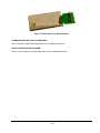
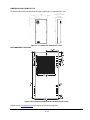
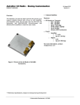
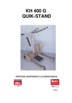
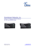
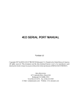
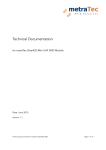
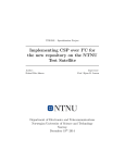
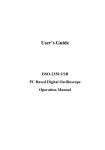
Li-1 Radio
Astronautical Development, LLC
www.astrodev.com
__________________________________________________________________________________________________________
Overview
Applications:
The Lithium radio product line provides a CubeSat
compatible communication system for extreme
environment applications.
Lithium radios feature
on-the-fly selectable frequency selection and output
power. They are compatible with standard amateur
radio ground stations capable of communication at 9600
bps, or higher bit rates using GMSK modulation.
• CubeSat Kit systems
• High altitude balloon missions
• Rovers or other remotely operated
vehicles
• Remote embedded systems
The Lithium series radios (Li-1) are half-duplex radios
with adjustable communications parameters. Custom
frequencies and deviations are available per customer
requirements.
• FSK/GMSK transceiver
• Frequencies:
o 130 – 450MHz
• Input voltages:
o Digital 3.3V
o Radio power supply (5-9V)
• Output transmit power: 250 mW – 4 W
• Power usage:
o Receive < 200 mW
o Transmit: < 10 W 1
• Data rate: 9.6 kbps 2
• Protocol support: AX.25
• Serial interface: 3.3V UART
• Form factor:
o SMT module (32 mm x 62 mm)
• Operating Temperature: -30 to +70 °C
The Lithium series radios are available as an SMT
module that can be placed on a half size PC104 board
or can be integrated into larger more complex systems
without incurring RF complexity in host products.
A digital command and data interface is provided to the
radios. Through this interface the radio is configured,
data is received, and data is sent for transmission. The
interface protocol is serial UART and configurable up to
115.2 kbps. A packet protocol with checksums is
implemented between the host and radio for robust
access.
The radios communicate using a subset of the AX.25
packet protocol (custom protocols can be ordered). The
AX.25 packet source and destination call signs are
configurable.
Features:
Options:
• AES 128 or 256 Encryption 3
• Connector options RA SMA, MCX
For more information, contact:
[email protected]
Li-1 emits RF radiation that may
interfere with the use of other
devices. Users must maintain
proper licenses during operation.
Li-1 is static sensitive, take the
necessary precautions
Figure 1--Picture of the Li-1 Radio.
Li-1 requires proper termination of
transmitter in 50 Ohm load during
operation.
1
Transmission power is configurable by the user. Maximum is noted.
Higher data rates require special licensing, 38.4kpbs, 76.8kbps.
3
Encryption not AX.25 compliant.
2
© Astronautical Development, LLC
www.astrodev.com
TABLE OF CONTENTS
ABSOLUTE MAXIMUM RATINGS ...................................................................................................................... 3
PHYSICAL CHARACTERISTICS ........................................................................................................................ 3
INTERFACE PIN DESCRIPTION......................................................................................................................... 3
LITHIUM MODULE SCHEMATIC DESCRIPTION............................................................................................... 4
PROGRAMMING PORT PIN DESCRIPTION ...................................................................................................... 4
LITHIUM MODULE PROGRAMMING PORT SCHEMATIC DESCRIPTION ...................................................... 4
COMMUNICATING WITH THE LITHIUM RADIO................................................................................................ 5
RADIO CONFIGURATION PROGRAM ............................................................................................................... 5
DIMENSIONS AND FORM FACTOR................................................................................................................... 6
RECOMMENDED FOOTPRINT ........................................................................................................................... 6
PROTECTING AGAINST ELECTROSTATIC DISCHARGE ............................................................................... 7
TRADEMARKS..................................................................................................................................................... 7
DISCLAIMER........................................................................................................................................................ 7
NOTES .................................................................................................................................................................. 7
© Astronautical Development, LLC
Li-1 User Manual
2 of 7
Revision 0.4 – 9/1/2009
ABSOLUTE MAXIMUM RATINGS
Interface Parameter
Operating temperature
DC Amplifier Voltage
DC Amplifier Current
DC 3.3V Radio Voltage
DC 3.3V Radio Current
Symbol
TOP
Vamp
Iamp
Vsys
Isys
Min.
Nom.
Max.
-30.0 to +70.0
5.0
9.0
0.1
1.5
3.0
3.3
3.6
0.02
0.03
0.07
Units
˚C
V
A
V
A
Input and Output Pins
Input Voltage Logic High
Input Voltage Logic Low
Current Source High
Current Sink Low
Symbol
Vhigh
Vlow
Ihigh
Ilow
Min.
2.6
0.0
Max.
3.6
0.66
Units
V
V
mA
mA
RF Interface
RF Output
Symbol
Min.
28
Nom.
Max.
34
Units
dBm
Symbol
M
H
W
L
Min.
48
0.0
Typ.
Max.
52
10
33
65
Units
g
mm
mm
mm
Nom.
3.3
10
10
PHYSICAL CHARACTERISTICS
Physical Parameter
Mass
Height
Width
Length
32
64
Please refer to IGS file information at www.astrodev.com for physical characteristics.
INTERFACE PIN DESCRIPTION
Interface Pin Name
TX_UART
RX_UART
RESET
GND
3.3V_RADIO
V_AMP
V_AMP
RF_GND
RF_GND
N/C
GND
External_Event
Config_Pin_2
Config_Pin_1
Thermal_PAD
Pin #
1
2
3
4
5
6
7
8
9
10
11
12
13
14
15
© Astronautical Development, LLC
Notes
UART TX, Information Out
UART RX, Information In
Reset radio, logic low
Radio supply ground
3.3V Radio supply
Amplifier Voltage
Amplifier Voltage
Amplifier Ground
Amplifier Ground
N/C
Radio supply ground
External event pin, configurable output
External configuration pin, logic input
External configuration pin, logic input
Bottom pad for thermal dissipation, connect to RF_GND
Li-1 User Manual
3 of 7
Revision 0.4 – 9/1/2009
LITHIUM MODULE SCHEMATIC DESCRIPTION
PCB
RESET
VCC_SYS
TX_UART
RX_UART
RESET
GND
3.3V_RADIO
6
7
8
9
V_AMP
V_AMP
RF_GND
RF_GND
Config 1
Config 2
External Event
GND
N/C
14
13
12
11
10
Config_Pin_1
Config_Pin_2
External Event
N/C
15
RADIO_RAW_VOLTAGE_IN
RADIO_RAW_VOLTAGE_IN
RF_GND1
RF_GND1
1
2
3
4
5
RF GND
TX_Uart
RX_Uart
RF_GND1
Li-1 Mount Module
Figure 2 Lithium PCB Mount Module Schematic Diagram
PROGRAMMING PORT PIN DESCRIPTION
Program Pin Name
DATA CLOCK
RESET
DATA
TCK
3.3VD
TDI
TMS
TDO
GND
N/C
Pin #
1
2
3
4
5
6
7
8
9
10
Notes
Reserved
JTAG Processor Reset
Reserved
JTAG Clock
JTAG 3.3V Power
JTAG Data In
JTAG Test Mode Select
JTAG Data Out
Ground
No Connection
LITHIUM MODULE PROGRAMMING PORT SCHEMATIC DESCRIPTION
Prog
DATA_CLOCK_11
DATA_11
+3.3VD
M1_TMS
1
3
5
7
9
2
4
6
8
10
M1_RST/NMI
M1_TCK
M1_TDI
M1_TDO
Header 5X2
Figure 3 Programming Port Schematic Diagram
The programming adapter provided with the radio converts the 1.27mm connector to a standard 0.1” JTAG
header. The JTAG adapter plugs inline with the radio with the majority of the adapter pointed away from the Li1 radio. In the following figure demonstrates the proper mating of the JTAG adapter.
© Astronautical Development, LLC
Li-1 User Manual
4 of 7
Revision 0.4 – 9/1/2009
Figure 4 JTAG Adapter Plug Demonstrations
COMMUNICATING WITH THE LITHIUM RADIO
Refer to AstroDev radio interface application note for detailed instructions.
RADIO CONFIGURATION PROGRAM
Refer to radio configuration program application note for detailed instructions.
© Astronautical Development, LLC
Li-1 User Manual
5 of 7
Revision 0.4 – 9/1/2009
DIMENSIONS AND FORM FACTOR
For detailed dimension information please refer to IGS model on www.astrodev.com
Figure 5 – Li-1 Radio (All dimensions in mm)
RECOMMENDED FOOTPRINT
Figure 6 Recommended PCB Footprint (All dimensions in mm)
Please refer to www.astrodev.com for footprints in PCB layout programs.
© Astronautical Development, LLC
Li-1 User Manual
6 of 7
Revision 0.4 – 9/1/2009
Mounting of the Li-1 module using hand soldering is recommended. An iron temperature of 350°C should be
used with IPC recommendations / reference documents IPC7711. Place the module precisely on the pads.
Start with a cross-diagonal fixture soldering (e.g. pins 14 and 9), and then continue from left to right. Thermal
compound should be applied to the thermal conduction area under the module. The thermal conduction area
should include through hole vias that connect to a ground plane to promote thermal dissipation. Proper
analysis is required to ensure that the module is able to properly dissipate heat within its application
environment.
Reflow or wave soldering of the Li-1 module is not recommended. Thermal dissipation through the module
heatsink occurs in high temperature environments resulting in inconsistent soldering joints.
Conformal coating or casting of the module is permitable as long as thermal analysis is performed to realize
the new thermal environment. The module should be operated at as low temperature as possible toward a
nominal 20 °C to increase overall efficiency and precise operation.
PROTECTING AGAINST ELECTROSTATIC DISCHARGE
CAUTION: Disconnect the Li-1 radio from power source before removing from operating environment.
Electrostatic discharge (ESD) events can harm electronic components inside the Li-1. Under certain
conditions, ESD may build up on your body or an object, such as an antenna, and then discharge into another
object, such as the Li-1. To prevent ESD damage, you should discharge static electricity from your body
before you interact with any electronic components.
You can protect against ESD and discharge static electricity from your body by touching a metal grounded
object (such as an unpainted metal surface such as your antistatic surface) before you interact with anything
electronic devices. When connecting an antenna or power plug to the Li-1, you should always ground both
yourself and the CubeSat structure before connecting it.
You can also take the following steps to prevent damage from electrostatic discharge:
• When unpacking the Li-1 from its shipping carton, do not remove the radio from the antistatic packing
material until you are ready to install the component. Just before unwrapping the antistatic package, be sure to
discharge static electricity from your body by wearing an antistatic wrist strap.
• When transporting the Li-1, first place it in an antistatic container or packaging.
• Handle the Li-1 in a static-safe area. If possible, use antistatic floor pads and work bench pads.
TRADEMARKS
In progress.
DISCLAIMER
All information in this document is subject to change at anytime. Look for continued updates at:
http://www.astrodev.com/
Lithium radios are sold as test devices and require users to gain experimental license from the FCC for use in
terrestrial and CubeSat satellite missions.
NOTES
© Astronautical Development, LLC
Li-1 User Manual
7 of 7
Revision 0.4 – 9/1/2009