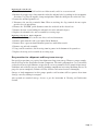
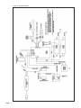
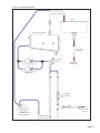
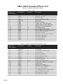
1
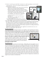
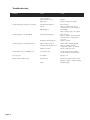
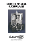
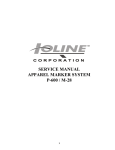
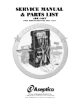
OPERATIONS,
SERVICE MANUAL
& PARTS LIST
ADU-42CF Portable Scrub Sink
NSN: 6530-01-572-6775
P.O. Box 1548 • Woodinville, WA 98072-1548
1-800-426-5913 • 425-487-3157 • Fax: 360-668-8722
email: [email protected] • Internet: www.aseptico.com
TABLE OF CONTENTS
Safety Precautions . . . . . . . . . . . . . . . . . . . . . . . . . . . . . . . . . . . . . . . . . . . . . . . . . . . . . . . . . . . . . . . . . . . . . . . . . . .2
Introduction . . . . . . . . . . . . . . . . . . . . . . . . . . . . . . . . . . . . . . . . . . . . . . . . . . . . . . . . . . . . . . . . . . . . . . . . . . . . . . . . .3
Purpose . . . . . . . . . . . . . . . . . . . . . . . . . . . . . . . . . . . . . . . . . . . . . . . . . . . . . . . . . . . . . . . . . . . . . . . . . . . . . . . . .3
Performance Characteristics . . . . . . . . . . . . . . . . . . . . . . . . . . . . . . . . . . . . . . . . . . . . . . . . . . . . . . . . . . . . . . . .3
Items Furnished . . . . . . . . . . . . . . . . . . . . . . . . . . . . . . . . . . . . . . . . . . . . . . . . . . . . . . . . . . . . . . . . . . . . . . . . . . .3
Preparation For Installation . . . . . . . . . . . . . . . . . . . . . . . . . . . . . . . . . . . . . . . . . . . . . . . . . . . . . . . . . . . . . . . . . . .4
Component Locations . . . . . . . . . . . . . . . . . . . . . . . . . . . . . . . . . . . . . . . . . . . . . . . . . . . . . . . . . . . . . . . . . . . . .4
Assembly . . . . . . . . . . . . . . . . . . . . . . . . . . . . . . . . . . . . . . . . . . . . . . . . . . . . . . . . . . . . . . . . . . . . . . . . . . . . . . . .5
Water Source Information . . . . . . . . . . . . . . . . . . . . . . . . . . . . . . . . . . . . . . . . . . . . . . . . . . . . . . . . . . . . . . . . . .6
Principles Of Operation . . . . . . . . . . . . . . . . . . . . . . . . . . . . . . . . . . . . . . . . . . . . . . . . . . . . . . . . . . . . . . . . . . . . . . .6
Water Delivery System . . . . . . . . . . . . . . . . . . . . . . . . . . . . . . . . . . . . . . . . . . . . . . . . . . . . . . . . . . . . . . . . . . . . .6
Heating System . . . . . . . . . . . . . . . . . . . . . . . . . . . . . . . . . . . . . . . . . . . . . . . . . . . . . . . . . . . . . . . . . . . . . . . . . . .7
Operating Instructions . . . . . . . . . . . . . . . . . . . . . . . . . . . . . . . . . . . . . . . . . . . . . . . . . . . . . . . . . . . . . . . . . . . . . . . .7
Start Up Procedure . . . . . . . . . . . . . . . . . . . . . . . . . . . . . . . . . . . . . . . . . . . . . . . . . . . . . . . . . . . . . . . . . . . . . . . .7
Soap Dispenser . . . . . . . . . . . . . . . . . . . . . . . . . . . . . . . . . . . . . . . . . . . . . . . . . . . . . . . . . . . . . . . . . . . . . . . . . . .7
Waste Water Management . . . . . . . . . . . . . . . . . . . . . . . . . . . . . . . . . . . . . . . . . . . . . . . . . . . . . . . . . . . . . . . . . .7
Shutdown Procedure . . . . . . . . . . . . . . . . . . . . . . . . . . . . . . . . . . . . . . . . . . . . . . . . . . . . . . . . . . . . . . . . . . . . . . .7
Daily Cleaning . . . . . . . . . . . . . . . . . . . . . . . . . . . . . . . . . . . . . . . . . . . . . . . . . . . . . . . . . . . . . . . . . . . . . . . . . . . .8
Daily Functional Checklist . . . . . . . . . . . . . . . . . . . . . . . . . . . . . . . . . . . . . . . . . . . . . . . . . . . . . . . . . . . . . . . . . .8
Cleaning And Lubrication . . . . . . . . . . . . . . . . . . . . . . . . . . . . . . . . . . . . . . . . . . . . . . . . . . . . . . . . . . . . . . . . . . . . .9
Performance Verification . . . . . . . . . . . . . . . . . . . . . . . . . . . . . . . . . . . . . . . . . . . . . . . . . . . . . . . . . . . . . . . . . . . . . .9
Troubleshooting Chart . . . . . . . . . . . . . . . . . . . . . . . . . . . . . . . . . . . . . . . . . . . . . . . . . . . . . . . . . . . . . . . . . . . . . . .10
Disassembly, Repair, Replacement . . . . . . . . . . . . . . . . . . . . . . . . . . . . . . . . . . . . . . . . . . . . . . . . . . . . . . . . . . . . .11
Circuit Breakers . . . . . . . . . . . . . . . . . . . . . . . . . . . . . . . . . . . . . . . . . . . . . . . . . . . . . . . . . . . . . . . . . . . . . . . . .11
Spout Guide . . . . . . . . . . . . . . . . . . . . . . . . . . . . . . . . . . . . . . . . . . . . . . . . . . . . . . . . . . . . . . . . . . . . . . . . . . . .11
Chassis . . . . . . . . . . . . . . . . . . . . . . . . . . . . . . . . . . . . . . . . . . . . . . . . . . . . . . . . . . . . . . . . . . . . . . . . . . . . . . . . .11
Heating Element . . . . . . . . . . . . . . . . . . . . . . . . . . . . . . . . . . . . . . . . . . . . . . . . . . . . . . . . . . . . . . . . . . . . . . . . .11
Level Sensors . . . . . . . . . . . . . . . . . . . . . . . . . . . . . . . . . . . . . . . . . . . . . . . . . . . . . . . . . . . . . . . . . . . . . . . . . . . .12
Intake Pumps . . . . . . . . . . . . . . . . . . . . . . . . . . . . . . . . . . . . . . . . . . . . . . . . . . . . . . . . . . . . . . . . . . . . . . . . . . . .12
Electronics Board . . . . . . . . . . . . . . . . . . . . . . . . . . . . . . . . . . . . . . . . . . . . . . . . . . . . . . . . . . . . . . . . . . . . . . . .12
Solenoid Valve . . . . . . . . . . . . . . . . . . . . . . . . . . . . . . . . . . . . . . . . . . . . . . . . . . . . . . . . . . . . . . . . . . . . . . . . . . .13
Spout Guide Seals . . . . . . . . . . . . . . . . . . . . . . . . . . . . . . . . . . . . . . . . . . . . . . . . . . . . . . . . . . . . . . . . . . . . . . . .13
Preparation For Shipment & Storage . . . . . . . . . . . . . . . . . . . . . . . . . . . . . . . . . . . . . . . . . . . . . . . . . . . . . . . . . . .13
Table of Illustrations
Figure A - Case Contents . . . . . . . . . . . . . . . . . . . . . . . . . . . . . . . . . . . . . . . . . . . . . . . . . . . . . . . . . . . . . . . . . . . . . .4
Figure B - Legs Pouch . . . . . . . . . . . . . . . . . . . . . . . . . . . . . . . . . . . . . . . . . . . . . . . . . . . . . . . . . . . . . . . . . . . . . . . . .4
Figure C - Electronics Pouch . . . . . . . . . . . . . . . . . . . . . . . . . . . . . . . . . . . . . . . . . . . . . . . . . . . . . . . . . . . . . . . . . . .4
Figure D - Soap Dispenser Pouch . . . . . . . . . . . . . . . . . . . . . . . . . . . . . . . . . . . . . . . . . . . . . . . . . . . . . . . . . . . . . . .4
Figure E - Plumbing Pouch . . . . . . . . . . . . . . . . . . . . . . . . . . . . . . . . . . . . . . . . . . . . . . . . . . . . . . . . . . . . . . . . . . . .4
Figure F - Leg Supports . . . . . . . . . . . . . . . . . . . . . . . . . . . . . . . . . . . . . . . . . . . . . . . . . . . . . . . . . . . . . . . . . . . . . . .5
Figure G - Spout Positions . . . . . . . . . . . . . . . . . . . . . . . . . . . . . . . . . . . . . . . . . . . . . . . . . . . . . . . . . . . . . . . . . . . . .5
Figure H - Connections . . . . . . . . . . . . . . . . . . . . . . . . . . . . . . . . . . . . . . . . . . . . . . . . . . . . . . . . . . . . . . . . . . . . . . .5
Figure I - Spout Connection . . . . . . . . . . . . . . . . . . . . . . . . . . . . . . . . . . . . . . . . . . . . . . . . . . . . . . . . . . . . . . . . . . .5
Figure J - Soap Dispenser . . . . . . . . . . . . . . . . . . . . . . . . . . . . . . . . . . . . . . . . . . . . . . . . . . . . . . . . . . . . . . . . . . . . .6
Figure K - Regulator Assembly . . . . . . . . . . . . . . . . . . . . . . . . . . . . . . . . . . . . . . . . . . . . . . . . . . . . . . . . . . . . . . . . .6
Figure L- Circuit Breakers . . . . . . . . . . . . . . . . . . . . . . . . . . . . . . . . . . . . . . . . . . . . . . . . . . . . . . . . . . . . . . . . . . . .11
Figure M - Spout Guide Removal . . . . . . . . . . . . . . . . . . . . . . . . . . . . . . . . . . . . . . . . . . . . . . . . . . . . . . . . . . . . . .11
Figure N - Ground . . . . . . . . . . . . . . . . . . . . . . . . . . . . . . . . . . . . . . . . . . . . . . . . . . . . . . . . . . . . . . . . . . . . . . . . . .11
Figure O - Heating Element . . . . . . . . . . . . . . . . . . . . . . . . . . . . . . . . . . . . . . . . . . . . . . . . . . . . . . . . . . . . . . . . . .11
Figure P - Level Sensors . . . . . . . . . . . . . . . . . . . . . . . . . . . . . . . . . . . . . . . . . . . . . . . . . . . . . . . . . . . . . . . . . . . . . .12
Figure Q - Intake Pumps . . . . . . . . . . . . . . . . . . . . . . . . . . . . . . . . . . . . . . . . . . . . . . . . . . . . . . . . . . . . . . . . . . . . .12
Figure R - Electronics Board . . . . . . . . . . . . . . . . . . . . . . . . . . . . . . . . . . . . . . . . . . . . . . . . . . . . . . . . . . . . . . . . . .12
Figure S - Wiring Schematic . . . . . . . . . . . . . . . . . . . . . . . . . . . . . . . . . . . . . . . . . . . . . . . . . . . . . . . . . . . . . . . . . . .14
Figure T - Plumbing Schematic . . . . . . . . . . . . . . . . . . . . . . . . . . . . . . . . . . . . . . . . . . . . . . . . . . . . . . . . . . . . . . . .15
Parts List . . . . . . . . . . . . . . . . . . . . . . . . . . . . . . . . . . . . . . . . . . . . . . . . . . . . . . . . . . . . . . . . . . . . . . . . . . . . . . .16-23
Page 2
SAFETY PRECAUTIONS:
Warning - Improper application, adjustment or servicing can result in serious injury.
Always disconnect power source before servicing.
Warning - Do not lean on the unit. Sink structure is not designed to support human weight.
Warning - Operating this equipment in a manner not specified in this manual may impair
protection features and reduce safety.
Caution - Prevent from freezing. Purge system before storage to prevent damage to lines or pumps.
Caution - Operate the sink in its upright position only. Tilting the sink at an extreme angle will
actuate the automatic shutoff level sensor, which will turn off the heating element.
Introduction
Purpose
The ADU-42CF Portable Scrub Sink provides a practical water source for mobile medical and
dental operations. Both warm and cold water are available for washing and instrument cleansing as
part of the process of disinfecting medical devices. Hands free operation makes surgical scrubs
simple. The rigid stainless steel basin and instrument basket are durable and easy to disinfect. And
the accessory tray allows sink-side consolidation of all instruments. Light weight and compact size
make the ADU-42CF easy to set-up and transport. To receive the best service and longest life from
your Aseptico product, follow the instructions detailed in this manual.
Performance characteristics
• Sink Wt: 50 lbs. (22.7 kg)
• Accessories (incl basket) Wt: 19 lbs. (8.6 kg)
• Shipping Case Wt: 35 lbs. (15.9 kg)
• Total Shipping Wt: 104 lbs. (47.2 kg)
• Size (external): 25.3 x 22.4 x 12.5 in. (64.3 x 56.9 x 31.8 cm)
• Sink flow rate: High - 0.95±0.2 gpm (3.6±0.75 lpm)
Low - 0.64±0.2 gpm (2.4±0.75 lpm)
• Max. pump discharge head: 8.3 ft (2.5 meters)
• Pump self priming limit: 48 in. (1.2 meters)
• Tank capacity: 1.45 Gal. (5.5 Litre)
• Tank Fill Time: Approximately 1-2 minutes (reference only).
• Heating capacity: 1400 Watts
• Tank Heating Time: Approximately 8 minutes from room temperature (reference only).
• Peak water temp.: 106° F, ±7°F (41°C, ±4°C)
• Cold water foot pump flow rate: 0.66 gpm (2.5 lpm) typical (reference only).
• Sink Basin Size: 21.3 x 15.4 x 7.4 in. (54.1 x 39.1 x 18.8 cm)
• Instrument Basket Size: 20.75 x 12.75 x 6 in. (52.7 x 32.4 x 15.2 cm)
Items furnished
• Sink unit, surgical
• Instrument Basket
• Aluminum legs (4).
• Intake and waste hoses.
• Cold water, manual pump.
• ON/OFF foot switch.
• 115V and 230V power cords.
• Instrument tray (6 1/2 x 10 in.).
• Grounding lug.
• Alternate source regulator.
• 2 copies Operations/Service Manual.
• Roll Towel Holder
• Hands-Free Soap Dispenser
• GFCI - Ground Fault Circuit Interrupter
LABORATORY
EQUIPMENT
38AJ
Items not furnished
• Jerry cans or alternate water supply.
• Waste water Jerry can.
Storage and handling precautions
• Avoid freezing. To protect internal
components, purge the sink’s tank and lines
prior to unattended periods in sub freezing
conditions.
Environmental conditions
• Operating Temperature: 1° to 45° C
(34° to 113° F)
• Transport/Storage Temperature: 1° to 60° C
(34° to 140° F)
• Relative Humidity: 5 to 95% non-condensing
• Altitude: 0 to 3048 meters (0 to 10,000 feet)
• Input Voltage Requirements:
115/230 VAC, 50/60Hz, single phase 12A
• Pollution Degree 2
Page 3
Preparations for use and installation instructions
After removal from its original packaging, the ADU-42CF will include the following items:
Case Contents: Fig A
1
Sink assembly (1)
3
Accessory pouches (3)
2
MIL-Spec carry case (1)
4
Soap Dispenser pouch (1)
6
Instrument Basket (1)
5
7
1
2
5
Legs pouch (1)
Figure A1 - Closed Case
Operation & Service Manuals (2)
(Not Shown)
Legs Pouch: Fig B
1
2
4
3
6
Figure A2 - Open Case with
Spout, Instrument Basket, & Accessories Pouches
2
Legs (4) & Leg Supports (2)
1
Legs pouch
Figure B - Legs Pouch
Electronics Pouch: Fig C
1
115V power cord
3
Foot switch
2
4
230V power cord
1
Mounting Bracket Assembly
3
Dispenser Bottle
4
4
Instrument tray
AA-42SD Soap Dispenser Pouch: Fig D
2
1
Foot Pedal & Hose Assembly
3
2
1
3
2
4
Figure C - Electronics Pouch
Paper Towel Holder
Figure D - AA-42SD Soap Dispenser Pouch
2
Plumbing Pouch: Fig E
1
Intake hose assembly
3
Cold water pump assembly
2
4
Page 4
Waste hose assembly
Alternate source regulator assembly
1
3
4
Figure E - Plumbing Pouch
Assembly
1. After removing the ADU-42CF Portable Sink from its original packaging, unfasten all perimeter
latches and open the lid. Locate the accessory pouches and lift the sink from the carry case.
Refer to Figure A
2. Leg-Supports: Refer to Figure F
a) Remove the four collapsible legs from the legs pouch and
unfold. Make sure the locking dowel engages completely. Insert
the legs into the guide tubes on the underside of the sink chassis
and twist to engage the lock-pin and secure.
b) Unfold the leg support sections and join together to make two
complete supports.
c) Insert right front sink leg into white plastic knuckle on end
of support. Insert right rear sink leg into other end
of support. Repeat on left side of sink with second support.
Leg Supports
Assembled
3. Raise the sink spout to the fully extended position and secure
locking cap over ball assembly to prevent spout from pivoting
downward. Refer to Figure G
4. Remove the contents of the plumbing pouch.
Attach the intake hose assembly to the quick
connect, labeled “WATER” on the underside
of the sink (Refer to Figure H). Immerse the
hose weight in the source jerry can (not
provided) to the preset distance and secure the
line using the attached push-on cap.
Figure F - Leg Supports
Storage
Position
5. Attach the waste hose to the Drain connection on
the underside of the sink. Place the opposite end in a
waste water jerry can (not provided). Secure the line using the
push on cap.
6. If desired, attach the components of the cold water pump
assembly (Refer to Figure E) to dispense cold water.
a) Unpack the manual foot pump and tubing assembly.
b) Place the foot pump on a level section of ground.
c) Attach the hose adapter to the sink spigot (Refer to Figure I).
Place the opposite end in a cold water jerry can (not provided).
Secure the line using the push on cap. Prime the lines by
depressing the foot pump several times, until water flows into the
sink. Refer to Figure E
7. Remove the contents of the electronics pouch. Attach the electric
ON/OFF foot switch to the foot switch connector, labeled
“FOOT SWITCH”, on the underside of the sink (Refer to Figure H).
Locking
Cap
Operation
Position
Figure G - Spout Positions
GFCI
Power Input
Grounding Stud
8. Unclip power input plug and cord (includes the Ground Fault Circuit
Interrupter - GFCI) from sink bottom, if desired (Refer to Figure H).
Select the appropriate power cord for the power source. Connect the
power cord to the input plug/cord and connect the other end to the
power source. Press the reset button on the GFCI. The sink will operate
on either a 115V or a 230V power supply. The green L.E.D. by the spout
will light, indicating power.
NOTE: The Ground Fault Circuit Interrupter will trip if power is
removed from the sink. This is its normal operation. When restoring
power to the sink, the GFCI must be reset after plugging in the mains
power cord.
Figure H - Connections
Hose
Adapter
Figure I - Spout Connection
Page 5
9. If desired, attach the paper towel holder, instrument tray and/or soap dispenser to sides of sink:
a) Instrument Tray : Secure the tray with the thumbscrews (Figure J).
c)
b) Soap Dispenser (Figure J):
b)
Cap
• Position the mounting bracket against the lip of the basin as
shown. Secure the bracket with the thumbscrew.
Soap
Spout
• Fill plastic dispenser bottle with medical-grade cleansing
agent/soap, to within 1/2-inch from top. Guide the mouth of
the plastic bottle over the lower end of the soap spout tube
a)
and carefully screw bottle upwards into the cap.
Tray
• Attach opposite end of foot pedal air-supply hose
Thumbscrew
to the hose fitting located on the underside of
the bottle cap.
• Slide bottle & cap assembly onto receiver plate
Foot
located on mounting bracket.
Pedal
c) Paper Towel Holder: Secure towel holder to other side
Figure J - Soap Dispenser
of sink, opposite the Instrument Tray and Soap Dispenser.
10.The ADU-42CF is constructed with full electrical protection, including a Ground Fault Circuit
Interrupter (GFCI). This equipment is intended for use with grounded power input. Provisions
have also been made to attach an external ground rod (not provided). Connection to the
ground rod may be made by securing a ground strap with a suitably sized lug to the grounding
terminal on the underside of the chassis with the wing nut provided and attaching the other end
of the ground strap to the grounding rod.
NOTE: Do not position the sink or place other equipment near the sink in such a way as to
impede access to the power outlet and cord.
Water Source Information
The ADU-42CF is designed to operate from jerry cans and from a variety of alternate water sources.
If the ADU-42CF is to be used with an alternate water supply, the source will determine the required
intake configuration. For operation from either a jerry can or a bladder water supply having a pressure
between -2 psi and 10 psi (a supply height ranging from 4 ft. below to 23 ft. above the sink basin)
appropriate flow rates can be generated by the sink’s internal pump.
Connection to this type of source can be made using the existing intake
tube. For connection to an established water source with an operating
pressure above 5 psi, the regulator assembly is recommended (Refer to
Figure K). Attachment is performed by disconnecting the intake hose
replacing it with the regulator assembly. A line from the water
supply having male garden hose threads can then be attached to
the Y-connector on the regulator assembly. Note: The manual foot
Figure K - Regulator Assembly
pump should be used in conjunction with a jerry can for cold water.
Principles Of Operation
Water Delivery System
Page 6
The water delivery system consists of two main pumps, a high/low flow switch, the solenoid valve, the
cold water foot pump and the alternate source regulator assembly. When the ON/OFF foot switch is
depressed, the internal electric pumps move water through the tank where it is warmed. The solenoid
valve serves as the flow control mechanism when the sink is operated from a pressurized water source.
The solenoid valve is normally closed and is actuated by depressing the foot switch. The cold water
foot pump manually delivers water from the source to the basin without warming. If required, the
manual pump may be used to partially prime the intake line. To use a pressurized water supply, the
regulator assembly should be connected between the sink and the water source, with the source
attached to the Y-connector on the regulator assembly. The regulator will reduce the water’s flow to
match the sink’s heating capacity and will dampen the effects of system pressure fluctuation. The
high/low flow switch, located on the top of the sink basin, switches the output of water from the two
pumps between maximum and minimum flow.
Heating System
The Heating System is composed of the tank, the extendable spout, the tank level sensor, the tilt
shutoff sensor, the control circuitry and the heating element. The tank is the reservoir for the water
to be heated. The tank level switch, located at the top of the tank, activates the heating element. To
allow the level switch to actuate and begin the water warming process, the sink must be standing in
its intended upright position. Tilting the sink at an extreme angle will actuate the automatic shutoff
sensor, which prevents damage to the sink's heating element. The orange L.E.D. by the spout will
light to indicate that the tank is full and the warming processes is active. The control circuitry will
regulate the heating process to a water temperature of 106 deg. Fahrenheit, ±7°F (41 deg.
Centigrade, ±4°C).
Operating instructions
Start-up procedure
Once the Set-Up is complete, prime the system by depressing the foot switch. Set the Flow Switch,
located on top of sink basin to the desired High or Low flow. Allow approximately 1-2 minutes for
the internal tank to fill. Release the foot switch when water begins to flow from the spout. The
orange L.E.D. by the spout will light, indicating that the heating element is active. The orange
L.E.D. will go out when the tank water is warmed. If desired, prime the cold water line by depressing
the foot pump several times until water flows into the sink.
To operate the sink, depress the ON/OFF foot switch for warm water or the foot pump for cold
water. Water will automatically be warmed as it flows through the internal water tank. The outlet
temperature will vary with consumption and source temperature. A full tank of room temperature
water will take approximately 8 minutes to warm to the shut off temperature of 106 deg. Fahrenheit
(41 deg. Centigrade).
Soap Dispenser
Position the soap dispenser foot pedal at a convenient location directly underneath sink. Press foot
pedal to dispense soap. Note: The foot pedal may require repeated pumping initially, to create
proper siphon pressure.
Waste Water Management
Fluid level in the waste container should be managed in such a way as to avoid overflow. This risk is
minimal when operating from a jerry can. When operating from a source greater than the waste jerry
can, care should be taken to monitor waste water level carefully.
Shut down procedures
1. Drain all water from the sink basin and clean the drain catch. Dry components before storage.
2. Drain and disconnect the cold water supply line and the drain hose. Use the manual pump to
assist in draining the cold water supply line.
3. Disconnect the intake hose from the quick connect labeled “WATER” and reattach it to the quick
connect labeled “PURGE”. If the water in the reservoir is to be reclaimed, leave the weighted
end of the intake hose in the source jerry can. Otherwise, purge the water in the tank to a waste
water jerry can or the ground. NOTE: To avoid contamination, minimize intake hose contact with
waste water.
4. When water stops flowing from the tank, depress the foot switch briefly. This process will purge
the pump and the internal supply lines. Release the foot switch when water ceases to flow from
the intake hose.
5. Disconnect all electrical power.
Page 7
6. Drain and disconnect the intake hose. Disinfect all hoses which have come into contact with waste
water using a dilute bleach solution.
7. Store the intake, cold water and drain hoses along with the alternate source regulator in the
plumbing pouch. Be sure to coil tubing carefully to avoid kinking. Dry components as thoroughly
as possible before storage.
8. Disconnect the ON/OFF foot switch, power cord, and instrument tray. Store these items in the
electronics accessories pouch. Disconnect soap dispenser if used and flush out the soap spout.
Pack and store dispenser components in pouch with paper towel holder. Clip power entry cord
and GFCI to underside of sink.
9. Twist loose and remove the four sink legs and leg supports. Fold and store components in their
appropriate pouches.
10. Place sink into the case with the sink sides aligned with case handles. Place the instrument basket
into the sink basin. Store the plumbing, electrical, and soap dispenser pouches in the instrument
basket. Place the legs pouch across top surface of basin, on left side of spout. Slide the Locking
Cap up the sink spout tube and pivot the spout forward until it lies flat with top surface of basin.
11.Close the lid and secure all perimeter latches. Reference figure A
Daily cleaning
All hoses which have come in contact with waste water during operation must be disinfected with a
dilute bleach or equivalent solution, prior to storage. Disinfect exposed sink parts in accordance with
conventional medical/dental practice.
Daily functional checklist
Observation of the following conditions will ensure that the ADU-42CF is functioning normally.
1. The green L.E.D. by the spout lights when the unit is connected to a power source.
2. The pumps can be heard running when the ON/OFF footswitch is depressed.
3. The spout is fully extended.
4. When the tank is filled, the orange L.E.D. lights indicating the heating element is operating.
5. Once primed, the intake lines retain their water level when the pump is not operating.
6. GFCI will trip when test button is pressed, and reset when reset button is pressed.
Page 8
Maintenance and
Servicing Instructions
Cleaning and lubrication
The external surfaces of the ADU-42CF’s chassis, spout, basin and accessory tray can be cleaned
with a commercial dental disinfectant. Sink hoses contacting waste water must be disinfected after
each session. To minimize the risk of corrosion, chlorine based cleaners should not be used to clean
the interior of the water storage tank or the sink’s legs. After a time the lines used in the plumbing
may develop a milky mineral deposit. This scale can be reduced by flushing the lines with a dilute
bleach or ammonium solution. External components will be sufficiently maintained by a cleaning
regiment consistent with standard medical and dental practice. Internal components do not require
lubrication or have special cleaning instructions.
Performance verification and Inspection
No specific inspection schedule needs to be maintained for this unit. Components have been selected
for their maintenance-free service life. The drain catch should be cleaned after each use. Verifying
that the following conditions are satisfied during operation will ensure proper function. These conditions should be verified as the final step of any major repair.
1. The green L.E.D. by the spout lights when the unit is connected to a power source.
2. The pumps can be heard running when the ON/OFF footswitch is depressed.
3. The tank fills when the footswitch has been depressed for approximately two minutes and the
orange L.E.D. lights to indicate the heating element is operational.
4. The orange L.E.D. goes out when the nominal water temperature of 106 degrees Fahrenheit (41
degrees Centigrade) is reached.
5. The orange L.E.D. relights and heating resumes when the heated water falls below the nominal
water temperature.
6. Once primed, the intake lines retain their water level when the pump is not operating.
Page 9
Troubleshooting
Problem
Not drawing water, pumps operating
Not drawing water, pumps not operating
Cause
No water source/intake tube
above water line.
Solenoid valve closed
Pump seals
Circuit breaker tripped
Diode
GFCI tripped
Not heating water, orange LED lit
Not heating water, orange LED not lit
Not heating water, green LED not lit
Leak at spout
Water leak from sink bottom
Page 10
Circuit breaker tripped
Heating element damaged
Tilt level sensor shut off
Circuit board, thermal sensor
Action
Add water to source/adjust intake hose
Replace
Replace pump(s) if required
Reset breaker
Inspect control board, replace
components or board as required
Reset GFCI
Inspect pumps, replace if required
Reset breaker
Inspect control board and heating
element, replace components as
necessary
Replace element
Tank Level sensor
Ensure sink is standing upright
Inspect control board and
components, replace as required
Replace tank level sensor
Seal failure
Replace seal
Tank
Tighten fittings
No system power
Internal leak
Check electrical source, GFCI,
circuit breakers, and connections.
Remove basin and search for leak
Tighten or replace clamps or tubing
Disassembly, Repair & Replacement
Note: The unit should only be powered when it is in an upright position. Operation with the tank
tilted at an extreme angle can cause the tilt shutoff sensor to actuate, shutting off the heater.
Important: Before beginning any repair, be sure to disconnect the sink from the power source.
Resetting the Circuit Breakers (Figure L)
The control board and heating element are protected by a 15A
circuit breaker and the pumps are protected by a 0.75A breaker.
Both breakers are located next to the power inlet on the bottom of
the chassis. A breaker that trips repeatedly is a symptom of a more
serious problem with one of the parent components. Inspect the
appropriate system elements if a breaker trips continuously, or
before replacing a breaker.
Figure L - Circuit Breakers
Access to internal components is gained by removing the spout guide and the sink chassis.
Spout guide removal (Figure M)
Tools: Channel lock pliers and 8 in. crescent wrench.
1. Loosen the 1.75 in. hex nut at the base of the spout guide.
2. Remove the spout guide from the heating tank by wrenching on the
flats on the sides of the pivotal spout guide.
3. Lift the spout assembly out of the tank.
4. Replace by reversing steps.
Chassis removal (Figure N)
Tools: 1/8 hex drive or Allen wrench and a 5/16 open-face wrench or
crescent wrench
5. Loosen the sixteen screws located around the perimeter of the sink
chassis.
6. Lift the sink chassis and locate the chassis ground lead and L.E.D.
wiring. Remove L.E.D. wiring connector from the control board. If
necessary, remove the ground lead from the sink chassis.
7. Reassemble by reversing steps.
Spout
Locking
Cap
Hex
Nut
Pivotal
Spout
Guide
Figure M- Spout Removal
Ground
Lead
Figure N - Ground
Once the interior of the sink has been accessed the following services can be performed:
Replacing the heating element (Figure O)
Tools: Phillips screwdriver, 8 in. crescent wrench, and 1/8 hex
drive or Allen wrench
1. Dismount tank from support flange.
2. Disconnect the heater ground and power leads at the
heating element.
3. Loosen the hardware securing the heating element to the
tank.
Power
Leads
4. Pull the heating element from the tank.
5. Apply a 1/4-inch bead of RTV sealant around the heater
slot, removing old sealant if necessary. Replace heater by
reversing the disassembly steps. Note: The attachment of
the power leads to the heating element does not require a
specific wire orientation.
Ground Lead
Figure O - Heating Element
Page 11
Replacing the level sensors (Figure P)
Tools: 8 in. crescent wrench, 1/4 in. socket, 5/64 in. Allen wrench.
1. Trace the electrical leads from the tank level sensor and tilt
shutoff sensor to the control board and remove the wiring
connector. Note the wiring configuration from the sensors to
the connector. Note the mating connector located on board.
2. Note the orientation, then unscrew the level sensor from the
tank. Remove the mounting hardware from the tilt level sensor.
3. Install the new sensors as required. On the tank sensor, make
sure the peaked portion of the exposed fitting labeled N.O.
(normally open) is positioned upward. Rewire and attach the
new electrical connector at the original board location.
Tank
Level Sensor
Replacing the electric intake pumps (Figure Q)
Tools: Pliers, 5/16 deep well socket or driver, and a
flat blade screwdriver
1. Remove the snapper type clamps from each end
of the pumps by pushing their tabs in opposite
directions. Use pliers to improve clamp manipulation. Work the tubing off each end of the
pumps.
Pump Wiring
Tilt
Shutoff
Sensor
Figure P - Level Sensor
Ground Wires
2. Loosen the green retaining screws and remove
the grounding wires from the pumps.
3. Remove the four nuts which mount the pumps
to the bracket and chassis.
4. Trace and disconnect the pumps wiring from the
control board and the solenoid valve. Connect
the new wires at the old locations.
Mounting Nut (X4)
Flow Direction Arrow
Figure Q - Intake Pumps
5. Replace the pump(s) as required and reassemble by reversing steps. Make sure that the flow direction arrow on the new pump(s) points away from the solenoid valve.
Replacing the pumps and tank tubing and clamps (Figure Q)
Tools: Small slip-jaw or flat pliers.
1. Check the clamps and tubing for cracks, splits, and leaks.
2. Remove snapper type clamps by pushing the clamp tabs in opposite directions. Use pliers to
improve clamp manipulation. Work the tubing off the barbs at each end.
3. Replace tubing with appropriate length as shown in the replacement parts list and Figure 2A,
pages 16-17.
4. If necessary, replace clamps with parts as indicated in parts list and Figure 2A, pages 16-17.
5. Secure clamps over tubing at barbs, using pliers if necessary to
ensure a tight, leak-free connection.
Replacing the electronics board (Figure R)
Tools: 1/4 open face wrench or crescent wrench, Phillips screwdriver, and pliers
1. Remove the board mounting hardware from each of the four
corners of the control board.
2. Wire the new board by tracing the leads from the old board or by
following the wiring schematic. Refer to Figure S.
Page 12
3. Secure the new control board in each corner with the mounting
hardware.
Figure R - Electronics Board
Replacing the solenoid valve
Tools: Pliers, 1/4 socket, 5/64 hex drive or Allen wrench, and 8 in. crescent wrench
1. Remove the snapper type clamp from the end of the solenoid valve by pushing its tabs in opposite
directions. Use pliers to improve clamp manipulation. Work the tubing off the end of the valve.
2. Loosen the solenoid ground lead.
3. Disconnect the two flag terminals. Note: When reattaching, the flag terminals do not require
specific valve tab orientation.
4. Remove the “WATER” quick disconnect from the underside of the chassis base.
5. Remove the four screws holding the solenoid vale to the solenoid adapter.
6. Replace the solenoid valve and reassemble by reversing steps.
Replacing seal in Spout
Refer to Figure M
Tools: Needle-nose pliers, small screw driver or dental instrument
1. Remove spout from the tank as per Spout Guide Removal.
2. Remove three capscrews from bottom of spout base with Allen wrench.
3. Remove cap and tube assembly.
3. Using a small screwdriver, lift the o-ring from its groove in the bottom of the spout base.
5. Replace the o-ring and reassemble by reversing steps.
Preparation for shipment and long term storage
No special preparations are required for shipment or long term storage. However, proper completion of all steps of the Shut-Down Section is important. The sink’s polypropylene case is internally
gasketed to be water tight. Moisture trapped in the case may promote bacteria growth in hot storage
conditions and residual water may damage plumbing components in freezing conditions. Be sure to
purge the system completely. Disinfect and dry all hoses and external surfaces thoroughly.
Storage of sink components in their proper pouches and locations will best protect them from
damage caused by shifting in transport.
After periods of extended storage, cleanse as per the instruction in Cleaning and Lubrication
Section.
Page 13
Figure S - Wiring Schematic
Page 14
Figure T - Plumbing Schematic
Spout Assembly
Basin
Water Storage Tank
Waste Hose
Assembly
Solenoid
Valve
Waste Water
Reservoir
Pumps (2)
Regulator
Assembly
Cold Water Foot
Pump Assembly
Alternate
Water Source
(5+ psi)
Water Source
(-2 psi to 10 psi)
Page 15
ADU-42CF Itemized Parts List
(Reference Final Assembly PN: 120352)
Figure and
Index Number
1-1
1-2
1-3
1-4
1-5
1-6
1-7
1-8
1-9
1-10
1-11
1-12
1-13
1-14
1-15
1-16
1-17
1-18
1-19
Part Number
730584-08
730585
461689
730292
330527-08
850061
520076
510594
510708
461688
510601
510677
510021
510428
510737
510216
830141
850036
420852
Figure 1 - Sink
Quantity
1
1
1
1
1
2
2
2
2
10
6
6
6
6
4
4
1
1
1
Description
Basin
Sink drain assembly
Drain adapter
Fitting, 1/2 NPT Hose BIB
Sink chassis
LED Lens Diffuser
O-Ring, .231 x .07w LED mount
Washer, Nylon .281 ID x .500 x .031
Hole Plug, 1.50 Dia Nylon Black
Sink Mounting Clip
Screw, PhdPhl 8-32x7/8 Stnls
Nut, .33 Square, 8-32 Steel Zinc Plated
Washer, SAE Flat Pltd #8
Nut, Hex 8-32 Stnls
Bolt, Squareneck Carriage, 10-24x1-1/2
Nut, Nyloc, 10-24 Stnls
Flow Switch, High/Low
Cover, Flow Switch
Label, Flow Switch
Parts List (continued)
Figure 2A - Reference Pump & Tank Assembly PN: 330522
Figure and
Index Number
2-1
2-2
2-3
2-4
2-5
2-6
2-7
2-8
2-9
2-10
2-11
2-12
2-13
2-14
2-15
2-16
2-17
2-18
2-19
Page 16
Part Number
Quantity
Description
330520-08
510256
461676-08
510428
510429
875096
875100
875094
730404
510448
460845
460846
875101
875095
875102
730587
510247
730667
730668
1
16
1
10
6
2
2
1
2.6 ft
12
1
1
1
1
1
4
4
1
1
Chassis base
Screw, BtnSoc 10-32x3/8 Stnls
Pump bracket
Nut, Hex 8-32 Stnls
Washer, split Stnls #8
Pump w/ wiring assembly
Pump ground wire
Chassis ground wire
Tubing, vinyl 3/4OD braid
Clamp, hose snapper type .569/.650
Solenoid valve
Solenoid valve adapter
Transformer, w/Wiring Harness
Wire Assy, Circuit Breakers
Wire Assy, Control Wire
Cap, Tubing vinyl for 1-1/4OD tubing
Screw, PhdPhl 8-32x3/8 Stnls
Fitting, Barb Y 3/8 Stnls
Fitting, Barb Tee 3/8 Stnls
6
17
7
4
8
11
3
12
2
15
13
16
9
14
10
18
1
5
10
19
(SINK BASIN - TOP VIEW)
Figure 1
16
10
17
9
10
12
15
11
10
19
4
5
4
5
6
7
3
9
8
18
14
13
4
5
1
2
Figure 2A
Page 17
Parts List (continued)
Figure 2B - Reference Pump & Tank Assembly PN: 330522
Figure and
Index Number
2-19
2-20
2-21
2-22
2-23
2-24
2-25
2-26
2-27
2-28
2-29
2-30
2-31
2-32
2-33
2-34
2-35
2-36
2-37
Part Number
Quantity
Description
830076
830140
510690
730636
730275
510452
510254
875091
840097
840098
875093
420550-08
420432-07
420295-04
420745
510699
510545
510021
510411
1
1
2
1
1
1
1
1
1
1
1
1
1
1
1
3
3
3
3
Circuit Breaker, 15 Amps
Circuit Breaker, 0.75 Amp
Washer, Lock, Push-On Circuit Breaker
FTG, QD, 1/2 NPT, Straight Through
Quick disconnect, male x 1/2 NPT(M)
Nut, Stnls wing 10-32
Nut, Hex 10-31 Stnls
Cable Assy, GFCI
Strain Relief 1/2 NPT
Nut, Locking Strain Relief
Footswitch connector w/ wiring
Label, Chassis
Label, UID, Serial Number
Label, Caution, Apply Power
Label, Chassis, Base
Clip, Cable, Nylon Open Sided 3/8 Dia
M/S, PhdPhl 8-32x1/2 Stnls
Washer, SAE Flat Pltd #8
Nut, Nyloc, 8-32 Stnls
Figure 3 - Reference Pump & Tank Assembly PN: 330522
Parts List (continued)
Figure and
Index Number
Page 18
3-1
3-2
3-3
3-4
3-5
3-6
3-7
3-8
3-9
3-10
3-11
3-12
3-13
3-14
3-15
3-16
3-17
3-18
3-19
3-20
3-21
3-22
3-23
3-24
Part Number
Quantity
Description
330519-08
510312
510421
510356
330516
510434
510433
510127
510131
510192
875097
730392
875099
875092
510254
510445
730275
730669
510206
Commercial
875098
875022
830139
510005
1
3
7
3
1
6
4
4
2
1
1
1
1
1
4
4
1
1
2
4
1
1
1
2
Water heater tank
Screw, BtnSoc 10-32x1/2 Stnls
Washer, Star int. #10 Stnls
Washer, Flat #10 Stnls
PC board assembly
Nut, Hex 4-40 Stnls
Washer, Split #4 Stnls
Washer, Flat nylon .120IDx.250ODx.032T
Washer, Nylon .143IDx.558ODx.032T
Washer, Flat #4 Stnls
Level sensor w/ wiring
Heating element
Heater power wire assembly - red
Heater power wire assembly - brown
Nut, Hex 10-32 Stnls
Washer, Fender 3/4ODx3/16ID
Quick disconnect, male x 1/2 NPT(M)
Fitting, 90 Deg. 1/2 MPT x 3/8 Barb Stnls
Mount, tie wrap
Tie wrap, 4 in.
LED assembly
Heater ground assembly
Switch Sealed Tilt Vibration Detector
Nut, Hex 4-40 Sml Ptn Pltd
19
21
26
32
34
35
36
37
29
27
28
31
22
30
20
21
23
33
24
25
Figure 2B
11
1
5
18
19
20
17
6
21
7
8
12
9
15
3
14
10
2
3
4
23
24
16
13
22
17
Figure 3
Page 19
Figure and
Index Number
4-1
4-2
4-3
4-4
4-5
4-6
4-7
4-8
4-9
4-10
4-11
4-12
(Not Shown)
(Not Shown)
Figure and
Index Number
Part Number
Quantity
Description
460823-08
461469-08
510610
510433
520079
461468-08
330533
461464
510608
461470
461537-08
730553-08
510668
510752
1
1
3
3
1
1
1
1
1
1
1
1
1
1
Nut, ADU-42CF spout guide
Cap, hot/cold spout
Screw, SocHd 4-40x5/8 Stnls
Washer, Split #4 Stnls
O-ring, 0.487 ID x 0.103 wide
Tank fitting, hot/cold spout
Spout assembly, hot/cold
Ball, spout
Spring, compression
Plunger, hot/cold spout
Cap, locking hot/cold
Fitting, Qd 5/16 Inch ID Mod
Washer, 18-8 SS 15/16IDx2-1/4ODx.192T
Washer, Rubber 3/4IDx2-1/4ODx1/8Thk
Figure 5 - Reference Legs Assembly PN:330521
Part Number
Quantity
Description
5-1
5-2
330521
410192-08
2
1
Sink legs assembly
Legs pouch
Figure and
Index Number
Part Number
Quantity
Description
330246
AE-7PM
840049
840007
410130-08
330550
1
1
1
1
1
1
Instrument tray
Footswitch
115V Power cord
230V power cord
Electrical components pouch
Instrument Basket 20.75 x 12.75 x 6
6-1
6-2
6-3
6-4
6-5
6-6
Figure and
Index Number
Page 20
Figure 4 - Reference Spout Assembly PN:120354
7-1
7-2
7-3
7-4
7-5
7-6
7-7
7-8
7-9
7-10
Figure 6 - Reference Electronics Pouch
Figure 7 - Reference Soap Dispenser Assembly PN: AA-42SD
Part Number
Quantity
Description
730583
510533
461679-08
510165
461981
461980
510019
510735
410190-08
330532
1
2
1
1
1
1
1
1
1
1
Dispenser, Soap 32oz foot operated
Screw, FlaPhl 8-32x1/2 Stnls
Bracket, Soap dispenser cmpl
Knob, Thumbscrew #10 knurl blk
C/S, SocHd 10-32x3/4Stnls mod
Spacer, Thumbscrew, knob
Washer, Nylon 0.196ID x 0.437OD x 0.62T
Ring, Retaining, Stnls E-clip for 3/16 dia shft
Pouch, storage soap dispenser
Paper towel assembly
12
9
7
10
2
8
5
(internal,
not shown)
2
3
11
4
8
6
1
Figure 4
5
3
1
1
Figure 5
6
4
2
Figure 6
9
2
1
3
3
10
4
5
6
7
8
Figure 7
Page 21
Figure 8 - Reference Waste Hose Assembly PN:330284, and Intake Hose Assembly PN:330252
Figure and
Index Number
8-1
8-2
8-3
8-4
8-5
8-6
8-7
9-1
9-2
9-3
9-4
9-5
9-6
9-7
9-8
9-9
9-10
9-11
10-1
10-2
10-3
10-4
10-5
10-6
10-7
10-8
(Not Shown)
(Not Shown)
(Not Shown)
Page 22
Part Number
Quantity
Description
730274
730404
510449
460843-08
460849
730295
410131-08
1
5 ft
1
1
2
1
1
Quick Disconnect, female x 1/2 barb
Tubing, vinyl 3/4 ODx1/2 ID braid
Clamp, Hose snapper style .702/.801
Intake hose weight
Push-on cap
Waste hose
Plumbing Components Pouch
Figure 9 - Reference Foot Pump Assembly PN:330458
460710
460182
730280
510733
510395
730554
510448
460843-08
460849
510449
730404
1
1
1
4
4
1
2
1
1
2
13 ft
Foot pump, base
Mat foot ramp ADU-40CF
Foot pump
M/S, Stnls, FlaPhl, 6-32 x 9/16
Nut, Nyloc, 6-32, Stnls, Hex
Fitting, QD, Straight 3/8” barb
Clamp, hose, snapper style, .569/.650
Intake hose weight
Adapter, ADU-40CF hose to can
Clamp, hose, snapper style, .702/.801
Tubing, vinyl, 0.594 ODx3/8 ID, braided
Figure 10 - Reference Water Pressure Regulator Assembly PN: 330285
730409
730639
730628
730415
510448
730274
510449
730404
1
1
1
1
1
1
1
3 ft.
Arrester assembly
FTN 3/4 garden hose x 1/4 NPT Swivel
Pressure Regulator
Fitting, 3/8 Hose Barb x 1/4 NPT
Clamp, hose snapper, .569/.650
Quick Disconnect, female x 1/2 barb
Clamp, hose snapper, .702/.801
Tubing, vinyl, .594OD x 3/8 ID, braided
410191-08
420752
420751-08
1
2
1
ADU-42CF Case
ADU-42CF Manual
Case Label
7
5
6
4
2
3
5
1
Figure 8
11
9
7
6
10
4
5
3
8
1
2
Figure 9
1
2
3
5
8
4
7
Figure 10
6
Page 23
ADU-42CF
Portable Scrub Sink
P.O. Box 1548 • Woodinville, WA 98072-1548
1-800-426-5913 • 425-487-3157 • Fax: 360-668-8722
email: [email protected] • Internet: www.aseptico.com
P/N 420752 • Rev. P • ECO 13574 • 03/2015