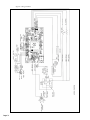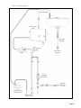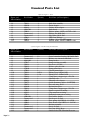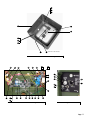
1
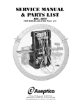
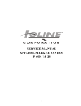
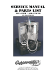
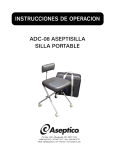
OPERATIONS,
SERVICE MANUAL
& PARTS LIST
ADU-40CF
NSN: 6520-01-456-5380
P.O. Box 1548 • Woodinville, WA 98072-1548
1-800-426-5913 • 425-487-3157 • Fax: 360-668-8722
email: [email protected] • Internet: www.aseptico.com
TABLE OF CONTENTS
Safety Precautions . . . . . . . . . . . . . . . . . . . . . . . . . . . . . . . . . . . . . . . . . . . . . . . . . . . . . . . . . . . . . . . . . . . . . . . . . . .2
Introduction . . . . . . . . . . . . . . . . . . . . . . . . . . . . . . . . . . . . . . . . . . . . . . . . . . . . . . . . . . . . . . . . . . . . . . . . . . . . . . . . .3
Purpose . . . . . . . . . . . . . . . . . . . . . . . . . . . . . . . . . . . . . . . . . . . . . . . . . . . . . . . . . . . . . . . . . . . . . . . . . . . . . . . . .3
Performance Characteristics . . . . . . . . . . . . . . . . . . . . . . . . . . . . . . . . . . . . . . . . . . . . . . . . . . . . . . . . . . . . . . . .3
Items Furnished . . . . . . . . . . . . . . . . . . . . . . . . . . . . . . . . . . . . . . . . . . . . . . . . . . . . . . . . . . . . . . . . . . . . . . . . . .3
Preparation For Installation . . . . . . . . . . . . . . . . . . . . . . . . . . . . . . . . . . . . . . . . . . . . . . . . . . . . . . . . . . . . . . . . . . .4
Component Locations . . . . . . . . . . . . . . . . . . . . . . . . . . . . . . . . . . . . . . . . . . . . . . . . . . . . . . . . . . . . . . . . . . . . .4
Assembly . . . . . . . . . . . . . . . . . . . . . . . . . . . . . . . . . . . . . . . . . . . . . . . . . . . . . . . . . . . . . . . . . . . . . . . . . . . . . . . .5
Water Source Information . . . . . . . . . . . . . . . . . . . . . . . . . . . . . . . . . . . . . . . . . . . . . . . . . . . . . . . . . . . . . . . . . .6
Principles Of Operation . . . . . . . . . . . . . . . . . . . . . . . . . . . . . . . . . . . . . . . . . . . . . . . . . . . . . . . . . . . . . . . . . . . . . . .6
Water Delivery System . . . . . . . . . . . . . . . . . . . . . . . . . . . . . . . . . . . . . . . . . . . . . . . . . . . . . . . . . . . . . . . . . . . . .6
Heating System . . . . . . . . . . . . . . . . . . . . . . . . . . . . . . . . . . . . . . . . . . . . . . . . . . . . . . . . . . . . . . . . . . . . . . . . . . .7
Operating Instructions . . . . . . . . . . . . . . . . . . . . . . . . . . . . . . . . . . . . . . . . . . . . . . . . . . . . . . . . . . . . . . . . . . . . . . . .7
Start Up Procedure . . . . . . . . . . . . . . . . . . . . . . . . . . . . . . . . . . . . . . . . . . . . . . . . . . . . . . . . . . . . . . . . . . . . . . .7
Waste Water Management . . . . . . . . . . . . . . . . . . . . . . . . . . . . . . . . . . . . . . . . . . . . . . . . . . . . . . . . . . . . . . . . . .7
Shutdown Procedure . . . . . . . . . . . . . . . . . . . . . . . . . . . . . . . . . . . . . . . . . . . . . . . . . . . . . . . . . . . . . . . . . . . . . .7
Daily Cleaning . . . . . . . . . . . . . . . . . . . . . . . . . . . . . . . . . . . . . . . . . . . . . . . . . . . . . . . . . . . . . . . . . . . . . . . . . . .8
Daily Functional Checklist . . . . . . . . . . . . . . . . . . . . . . . . . . . . . . . . . . . . . . . . . . . . . . . . . . . . . . . . . . . . . . . . .8
Cleaning And Lubrication . . . . . . . . . . . . . . . . . . . . . . . . . . . . . . . . . . . . . . . . . . . . . . . . . . . . . . . . . . . . . . . . . . . . .9
Performance Verification . . . . . . . . . . . . . . . . . . . . . . . . . . . . . . . . . . . . . . . . . . . . . . . . . . . . . . . . . . . . . . . . . . . . . .9
Troubleshooting Chart . . . . . . . . . . . . . . . . . . . . . . . . . . . . . . . . . . . . . . . . . . . . . . . . . . . . . . . . . . . . . . . . . . . . . . .10
Disassembly, Repair, Replacement . . . . . . . . . . . . . . . . . . . . . . . . . . . . . . . . . . . . . . . . . . . . . . . . . . . . . . . . . . . . .11
Spout Guide Removal . . . . . . . . . . . . . . . . . . . . . . . . . . . . . . . . . . . . . . . . . . . . . . . . . . . . . . . . . . . . . . . . . . . .11
Chassis Removal . . . . . . . . . . . . . . . . . . . . . . . . . . . . . . . . . . . . . . . . . . . . . . . . . . . . . . . . . . . . . . . . . . . . . . . . .11
Fuses . . . . . . . . . . . . . . . . . . . . . . . . . . . . . . . . . . . . . . . . . . . . . . . . . . . . . . . . . . . . . . . . . . . . . . . . . . . . . . . . . .11
Heating Element . . . . . . . . . . . . . . . . . . . . . . . . . . . . . . . . . . . . . . . . . . . . . . . . . . . . . . . . . . . . . . . . . . . . . . . .11
Level Sensor . . . . . . . . . . . . . . . . . . . . . . . . . . . . . . . . . . . . . . . . . . . . . . . . . . . . . . . . . . . . . . . . . . . . . . . . . . . .12
Intake Pump . . . . . . . . . . . . . . . . . . . . . . . . . . . . . . . . . . . . . . . . . . . . . . . . . . . . . . . . . . . . . . . . . . . . . . . . . . . .12
Electronics Board . . . . . . . . . . . . . . . . . . . . . . . . . . . . . . . . . . . . . . . . . . . . . . . . . . . . . . . . . . . . . . . . . . . . . . . .12
Solenoid Valve . . . . . . . . . . . . . . . . . . . . . . . . . . . . . . . . . . . . . . . . . . . . . . . . . . . . . . . . . . . . . . . . . . . . . . . . . .13
Spout Guide Seals . . . . . . . . . . . . . . . . . . . . . . . . . . . . . . . . . . . . . . . . . . . . . . . . . . . . . . . . . . . . . . . . . . . . . . .13
Preparation For Shipment & Storage . . . . . . . . . . . . . . . . . . . . . . . . . . . . . . . . . . . . . . . . . . . . . . . . . . . . . . . . . .13
Table of Illustrations
Figures A1 & A2 - Case Contents . . . . . . . . . . . . . . . . . . . . . . . . . . . . . . . . . . . . . . . . . . . . . . . . . . . . . . . . . . . . . . .4
Figures B1 & B2 - Legs Pouches . . . . . . . . . . . . . . . . . . . . . . . . . . . . . . . . . . . . . . . . . . . . . . . . . . . . . . . . . . . . . . . .4
Figure C - Electronics Pouch . . . . . . . . . . . . . . . . . . . . . . . . . . . . . . . . . . . . . . . . . . . . . . . . . . . . . . . . . . . . . . . . . . .4
Figure D - Optional Soap Dispenser Pouch . . . . . . . . . . . . . . . . . . . . . . . . . . . . . . . . . . . . . . . . . . . . . . . . . . . . . .4
Figure E - Plumbing Pouch . . . . . . . . . . . . . . . . . . . . . . . . . . . . . . . . . . . . . . . . . . . . . . . . . . . . . . . . . . . . . . . . . . . .4
Figure F - Optional Leg Supports . . . . . . . . . . . . . . . . . . . . . . . . . . . . . . . . . . . . . . . . . . . . . . . . . . . . . . . . . . . . . . .5
Figures G1 & G2 - Spout Positions . . . . . . . . . . . . . . . . . . . . . . . . . . . . . . . . . . . . . . . . . . . . . . . . . . . . . . . . . . . . . .5
Figure H - Connections . . . . . . . . . . . . . . . . . . . . . . . . . . . . . . . . . . . . . . . . . . . . . . . . . . . . . . . . . . . . . . . . . . . . . . .5
Figure I - Spout Connection . . . . . . . . . . . . . . . . . . . . . . . . . . . . . . . . . . . . . . . . . . . . . . . . . . . . . . . . . . . . . . . . . . .5
Figure J - Optional Soap Dispenser . . . . . . . . . . . . . . . . . . . . . . . . . . . . . . . . . . . . . . . . . . . . . . . . . . . . . . . . . . . . .6
Figure K - Regulator Assembly . . . . . . . . . . . . . . . . . . . . . . . . . . . . . . . . . . . . . . . . . . . . . . . . . . . . . . . . . . . . . . . . .6
Figures L1 & L2 - Spout Guides Removal . . . . . . . . . . . . . . . . . . . . . . . . . . . . . . . . . . . . . . . . . . . . . . . . . . . . . . .11
Figure M - Ground . . . . . . . . . . . . . . . . . . . . . . . . . . . . . . . . . . . . . . . . . . . . . . . . . . . . . . . . . . . . . . . . . . . . . . . . . .11
Figure N - Fuse . . . . . . . . . . . . . . . . . . . . . . . . . . . . . . . . . . . . . . . . . . . . . . . . . . . . . . . . . . . . . . . . . . . . . . . . . . . . .11
Figure O - Heating Element . . . . . . . . . . . . . . . . . . . . . . . . . . . . . . . . . . . . . . . . . . . . . . . . . . . . . . . . . . . . . . . . . .11
Figure P - Level Sensor . . . . . . . . . . . . . . . . . . . . . . . . . . . . . . . . . . . . . . . . . . . . . . . . . . . . . . . . . . . . . . . . . . . . . .12
Figure Q - Intake Pump . . . . . . . . . . . . . . . . . . . . . . . . . . . . . . . . . . . . . . . . . . . . . . . . . . . . . . . . . . . . . . . . . . . . . .12
Figure R - Electronics Board . . . . . . . . . . . . . . . . . . . . . . . . . . . . . . . . . . . . . . . . . . . . . . . . . . . . . . . . . . . . . . . . . .12
Figure S - Wiring Schematic . . . . . . . . . . . . . . . . . . . . . . . . . . . . . . . . . . . . . . . . . . . . . . . . . . . . . . . . . . . . . . . . . .14
Figure T - Plumbing Schematic . . . . . . . . . . . . . . . . . . . . . . . . . . . . . . . . . . . . . . . . . . . . . . . . . . . . . . . . . . . . . . . .15
Parts List . . . . . . . . . . . . . . . . . . . . . . . . . . . . . . . . . . . . . . . . . . . . . . . . . . . . . . . . . . . . . . . . . . . . . . . . . . . . . . .16-23
SAFETY PRECAUTIONS:
Warning - Improper application, adjustment or servicing can result in serious injury.
Always disconnect power source before servicing.
Warning - Do not lean on the unit. Sink structure is not designed to support human weight.
Caution - To avoid the risk of burns do not adjust the storage tank temperature control above
120 deg. Fahrenheit.
Caution - Prevent from freezing. Purge system before storage to prevent damage to lines or pump.
Page 2
Introduction
Purpose
The ADU-40CF Command Air Portable Field Sink provides a practical water source for mobile
medical and dental operations. Both warm and cold water are available for washing and instrument
cleansing as part of the process of disinfecting medical devices. Hands free operation makes surgical
scrubs simple. The rigid stainless steel basin is durable and is easy to disinfect. And the accessory
tray allows sink-side consolidation of all instruments. Light weight and compact size make the ADU40CF easy to set-up and transport. To receive the best service and longest life from your Aseptico
product, follow the instructions detailed in this manual.
Performance characteristics
• Weight: 48 lb.
• Size: 19 x 19 x 14 in. (external)
• Sink flow rate: 0.68 gpm (2.2 lpm)
• Max. pump discharge head: 8.3 ft (2.5 meters)
• Pump self priming limit: 48 in. (1.2 meters)
• Heating capacity: 1500 Watts
• Tank capacity: 0.75 Gal. (2.9 Litre)
• Peak water temp.: 106° F, ±7°F (41°C, ±4°C)
Items furnished
• Sink unit, surgical
• Aluminum legs (4).
• Intake and waste hoses.
• Cold water, manual pump.
• ON/OFF foot switch.
• 120V and 230V power cords.
• Instrument tray (6 1/2 x 10 in.).
• Grounding lug.
• Alternate source regulator.
• 2 copies Operations/Service Manual.
Items not furnished
• Jerry cans or alternate water supply.
• Waste water Jerry can.
• 120/230, 50/60Hz, single phase electrical
power supply.
Storage and handling precautions
• Avoid freezing. To protect internal
components, purge the sink’s tank and lines
prior to unattended periods in sub freezing
conditions.
Environmental conditions
• Operating Temperature: 1° to 45° C
(34° to 113° F)
• Transport/Storage Temperature: 1° to 60° C
(34° to 140° F)
• Relative Humidity: 5 to 95% non-condensing
• Altitude: 0 to 3048 meters (0 to 10,000 feet)
WARNING: This device has been tested and found to comply with the emissions requirements of IEC 60601-1-2:2001-09. These
requirements provide reasonable protection against harmful electromagnetic interference in a typical medical installation. However,
high levels of radio-frequency (RF) emissions from electrical devices, such as cellular phones, may disrupt the performance of this
device. To mitigate disruptive electromagnetic interference, position this device away from RF transmitters and other sources of
electromagnetic energy.
Page 3
Preparations for use and installation instructions
After removal from its original packaging, the ADU-40CF will include the following items:
Case Contents: Figs A1 & A2
1
Sink assembly (1)
2
MIL-Spec carry case (1)
3
Operation & Service Manuals (2)
4
Accessory pouches (3)
5
Optional Soap Dispenser pouch (1)
6
Optional Leg Support Kit pouch (1)
3
3
6
1
4
4
1
5
2
2
Figure A1 - Open Case with
Accessories Pouches
Figure A2 - Open Case with
Optional Spout &
Optional Accessories Pouches
Legs Pouches (in lid): Figs 2A & 2B
1
Legs (4)
2
Optional AA-04CF Legs-Support Kit
1
2
Figure B1 - Legs Pouch
Figure B2 - Optional AA-04CF
Legs Support Kit Pouch
Electronics Pouch (in basin): Fig C
1
120V power cord
2
230V power cord
3
Foot switch
4
Instrument tray
Optional AA-04SD Soap Dispenser
Pouch: Fig D
1
Mounting Bracket Assembly
2
Foot Pedal & Hose Assembly
3
Dispenser Bottle
4
1
3
1
2
2
3
Figure C - Electronics Pouch
Figure D - Optional AA-04SD
Soap Dispenser Pouch
2
Plumbing Pouch (in basin): Fig E
Page 4
1
Intake hose assembly
2
Waste hose assembly
3
Cold water pump assembly
4
Alternate source regulator assembly
1
3
4
Figure E - Plumbing Pouch
Assembly
1. After removing the ADU-40CF Command Air Field Sink from its original packaging, unfasten all
perimeter latches and remove the cover. Locate the accessory pouches and lift the sink from the
carry case. Refer to Figure A
2. Remove the four collapsible legs from the legs pouch and unfold. Make sure the locking dowel
engages completely. Insert the legs into the guide tubes on the
underside of the sink chassis and twist to engage the lock-pin and
secure.
3. Optional Leg-Support Kit: Refer to Figure F
a) Remove the black rubber feet from the existing sink legs.
b) Unfold the optional leg support sections and join together
to make two complete supports.
Optional
c) Insert right front sink leg into white plastic knuckle on end
Leg Supports
of optional support. Insert right rear sink leg into other end
Assembled
of support. Repeat on left side of sink with second support.
(Note: The leg supports will also function properly when Figure F - Optional Leg Supports
installed between the two front sink legs and two back legs.)
4. Raise the sink spout to the fully extended position. Refer to Figures G1 & G2
Storage
Position
Operation
Position
Figure G1 - Spout Position
Storage
Position
Operation
Position
Figure G2 - Optional AA-04EXS 15-Inch Spout Position
5. Remove the contents of the plumbing pouch. Attach the intake hose assembly to the quick
connect, labeled “WATER INPUT” on the underside of the
sink. Immerse the hose weight in the source jerry can (not
provided) to the preset distance and secure the line using the
attached push-on cap. Refer to Figure H
6. Attach the waste hose to the underside of the sink. Place the
opposite end in a waste water jerry can (not provided). Secure
the line using the push on cap. Refer to Figure H
7. If desired, attach the components of the cold water pump
assembly (refer to Figure E) to dispense cold water.
a) Unpack the manual foot pump and tubing assembly.
Grounding Stud
b) Attach the hose adapter to the sink spigot. Refer to Figure I
c) Place the foot pump on a level section of ground and attach the
Figure H - Connections
other end to water source. Prime the lines
by depressing the foot pump several times, until water flows into the sink.
Refer to Figure E
Hose Adapter
Instrument
Tray
Figure I - Spout Connection
8. Remove the contents of the electronics pouch. Attach the electric
ON/OFF foot switch to the foot switch connector, labeled “FOOT
SWITCH”, on the underside of the sink. Refer to Figure H
9. Select the appropriate power cord for the power source. Connect the cord
on the underside of the sink and secure it using the retaining clip connector.
Plug the other end into the power source. The sink will operate on either a
120V or a 230V power supply. The green L.E.D. by the spout will light
indicating power. Refer to Figure H
Page 5
10. If desired, attach the instrument tray and/or optional soap dispenser to either side of the sink :
a) Instrument Tray : Secure the tray with the thumbscrews (Figure I).
b) Optional Soap Dispenser (Refer to Figure J):
• Position the mounting bracket against the lip of the basin as
shown. Secure the bracket with the thumbscrew.
• Fill plastic dispenser bottle with medical-grade cleansing
agent/soap, to within 1/2-inch from top.
• Guide the mouth of the plastic bottle over the lower end of the
soap spout and carefully screw bottle upwards into the cap.
• Attach opposite end of 1/4-inch clear air hose (mounted to top
of bottle cap) to the quick disconnect located on the end of the
foot pedal air-supply hose.
11. The ADU-40CF is constructed with full electrical protection;
however, provisions have been made to attach an external ground
rod (not provided) to a grounding stud on the underside of the sink.
Refer to Figure H
Soap
Spout
Thumbscrew
Quick
Disconnect
Figure J - Optional AA-04SD
Soap Dispenser
Water Source Information
The ADU-40CF is designed to operate from jerry cans and from a variety of alternate water
sources. If the ADU-40CF is to be used with an alternate water supply, the source will determine
the required intake configuration. For operation from either a jerry can or a bladder water supply
having a pressure between -2 psi and 10 psi (a supply height ranging from 4 ft. below to 23 ft.
above the sink basin) appropriate flow rates can be
generated by the sink’s internal pump. Connection to
this type of source can be made using the existing
intake tube. For connection to an established water
source with an operating pressure above 5 psi, the
regulator assembly is recommended. Attachment is
performed by disconnecting the intake hose and
replacing it with the regulator assembly. Refer to Figure
K. A line from the water supply having male garden
hose threads can then be attached to the Y-connector
on the regulator assembly. Note: The cold water foot
pump should be used in conjunction with a jerry can for
cold water.
Figure K - Regulator Assembly
Principles Of Operation
Water Delivery System
The water delivery system consists of the main pump, the solenoid valve, the cold water foot pump
and the alternate source regulator assembly. When the ON/OFF foot switch is depressed, the
internal electric pump moves water through the tank where it is warmed. The solenoid valve serves
as the flow control mechanism when the sink is operated from a pressurized water source. The
solenoid valve is normally closed and is actuated by depressing the foot switch. The cold water foot
pump manually delivers water from the source to the basin without warming. If required, the
manual pump may be used to partially prime the intake line. To use a pressurized water supply the
regulator assembly should be connected between the sink and the source. The regulator will reduce
the water’s flow to match the sink’s heating capacity and will dampen the effects of system pressure
fluxuation.
Page 6
Heating System
The Heating System is composed of the tank, the extendible spout, the tank level sensor, the tilt
shutoff sensor, the control circuitry and the heating element. The tank is the reservoir for the water
to be heated. The spout position determines the volume of water stored in the tank. The tank level
switch, located at the top of the tank, activates the heating element. To allow the level switch to
actuate and begin the water warming process, the spout must be in the extended position and the
sink must be standing in its intended upright position. Tilting the sink at an extreme angle will
actuate the automatic shutoff sensor, which prevents damage to the sink's heating element. The
orange L.E.D. by the spout will light to indicate that the tank is full and the warming processes is
active. The control circuitry will stop the heating process when the water temperature reaches 106
deg. Fahrenheit, ±7°F (41 deg. Centigrade, ±4°C). Heating will resume when the water temperature falls below 97 deg. Fahrenheit (36 deg. Centigrade).
Operating instructions
Start-up procedure
Once the Set-Up is complete, prime the system by depressing the foot switch. Allow one and a half
minutes for the internal tank to fill. Release the foot switch when water begins to flow from the
spout. The orange L.E.D. by the spout will light when the tank has filled indicating that the heating
element is active. The orange L.E.D. with go out when the tank water is warmed. If desired, prime
the cold water line by depressing the foot pump several times until water flows into the sink.
To operate the sink depress the ON/OFF foot switch for warm water or the foot pump for cold
water. Water will automatically be warmed as it flows through the internal water tank. The outlet
temperature will vary with consumption and source temperature. As a general rule, a full tank of
room temperature water will take two and a half to three minutes to warm to the shut off
temperature of 106 deg. Fahrenheit (41 deg. Centigrade).
Optional Soap Dispenser
Position the optional soap dispenser foot pedal at a convenient location directly underneath sink.
Press foot pedal to dispense soap. Note: The foot pedal may require repeated pumping initially, to
create proper siphon pressure.
Waste Water Management
Fluid level in the waste container should be managed in such a way as to avoid overflow. This risk is
minimal when operating from a jerry can. When operating from a source greater than the waste jerry
can, care should be taken to monitor waste water level carefully.
Shut down procedures
1. Drain all water from the sink basin and clean the drain catch. Dry components before storage.
2. Drain and disconnect the cold water supply line and the drain hose. Use the manual pump to
assist in draining the cold water supply line.
3. Disconnect the intake hose from the quick connect labeled “WATER INPUT” and reattach it to
the quick connect labeled “PURGE”. If the water in the reservoir is to be reclaimed, leave the
weighted end of the intake hose in the source jerry can. Otherwise, purge the water in the tank
to a waste water jerry can or the ground. NOTE: To avoid contamination, minimize intake hose
contact with waste water.
4. When water stops flowing from the tank, depress the foot switch briefly while intermittently
pressing upward on the nub of the “WATER INPUT” quick disconnect. This process will purge
the pump and the internal supply lines. Release the foot switch when water ceases to flow from
the intake hose.
5. Disconnect all electrical power
Page 7
6. Drain and disconnect the intake hose. Disinfect all hoses which have come into contact with waste
water using a dilute bleach solution.
7. Store the intake, cold water and drain hoses along with the alternate source regulator in the
plumbing pouch. Be sure to coil tubing carefully to avoid kinking. Dry components as thoroughly
as possible before storage.
8.Disconnect the ON/OFF foot switch, power cord, and instrument tray. Store these items in the
electronics accessories pouch. Disconnect optional soap dispenser if used and flush out the soap
spout. Pack and store dispenser components in pouch.
9. Twist loose and remove the four sink legs, or optional leg supports if used. Fold and store
components in their appropriate pouches.
10. Place the sink into the case with the sink sides aligned with the case handles. Store the plumbing
and electrical pouches, and optional soap dispenser pouch if used, in the sink basin. Lower the
sink spout, or slide the Locking Cap up the tube and pivot the optional 15-inch spout forward until
it lies flat with top surface of basin.
11.Store the leg and optional leg-support pouches in the lid. Place the lid and secure all perimeter
latches. Reference figure A
Daily cleaning
All hoses which have come in contact with waste water during operation must be disinfected with a
dilute bleach or equivalent solution, prior to storage. Disinfect exposed sink parts in accordance with
conventional medical/dental practice.
Daily functional checklist
Observation of the following conditions will ensure that the ADU-40CF is functioning normally.
1. The green L.E.D. by the spout lights when the unit is connected to a power source.
2. The pump can be heard running when the ON/OFF footswitch is depressed.
3. The spout is fully extended.
4. When the tank is filled the orange L.E.D. lights indicating the heating element is operating.
5. Once primed, the intake lines retain their water level when the pump is not operating.
Page 8
Maintenance and
Servicing Instructions
Cleaning and lubrication
The external surfaces of the ADU-40CF’s chassis, spout, basin and accessory tray can be cleaned
with a commercial dental disinfectant. Sink hoses contacting waste water must be disinfected after
each session. To minimize the risk of corrosion, chlorine based cleaners should not be used to clean
the interior of the water storage tank or the sink’s legs. After a time, the lines used in the plumbing
may develop a milky mineral deposit. This scale can be reduced by flushing the lines with a dilute
bleach or ammonium solution. External components will be sufficiently maintained by a cleaning
regiment consistent with standard medical and dental practice. Internal components do not require
lubrication or have special cleaning instructions.
Performance verification and Inspection
No specific inspection schedule needs to be maintained for this unit. Components have been selected
for their maintenance free service life. The drain catch should be cleaned after each use. Verifying
that the following conditions are satisfied during operation will ensure proper function. These
conditions should be verified as the final step of any major repair.
1. The green L.E.D. by the spout lights when the unit is connected to a power source.
2. The pump can be heard running when the ON/OFF footswitch is depressed.
3. The tank fills when the footswitch has been depressed for two minutes and the orange L.E.D.
lights to indicate the heating element is operational.
4. The orange L.E.D. goes out when the peak water temperature of 106 degrees Fahrenheit (41
degrees Centigrade) is reached.
5. The orange L.E.D. relights and heating resumes when the heated water falls below a temperature
of 97 degrees Fahrenheit (36 degrees Centigrade).
6. Once primed the intake lines retain their water level when the pump is not operating.
Page 9
Troubleshooting
Problem
Cause
Action
Not drawing water, pump operating
No water source/intake tube
above water line.
Solenoid valve closed
Pump seals
Add water to source/adjust intake hose
Not drawing water, pump not operating
Fuse blown
Diode
Inspect pump, replace if required
Inspect control board, replace
components or board as required
Not heating water, orange LED lit
Heating element fuse blown
Inspect control board and heating
element, replace components as
necessary
Replace element
Heating element damaged
Not heating water, orange LED not lit
Page 10
Replace
Replace pump
Spout not raised
Tilt switch shut off
Circuit board, thermal sensor
Level sensor
Raise spout
Ensure sink is standing upright
Inspect control board and
components, replace as required
Replace level sensor
Not heating water, green L.E.D. not lit
No system power
Check electrical source and connections.
Leak at spout
Seal failure
Replace seal
Water leak from sink bottom
Internal leak
Remove basin and search for leak
Tighten or replace clamps or tubing
Tank
Tighten fittings
Disassembly, Repair & Replacement
Note: The unit should only be powered when it is in the upright position. Operation with the tank
tilted at an extreme angle can cause the tilt shutoff sensor to actuate, shutting off the heater.
Note: Before beginning any repair, be sure to disconnect the sink from the power source.
Access to internal components is gained by removing the spout guide and the sink chassis.
Spout guide removal (Figures L1 & L2)
Tools: Channel lock pliers and 8 in.
crescent wrench.
1. Loosen the 1.75 in. hex nut at the base of
the spout guide.
2. Remove the spout guide from the heating
tank by wrenching on the hex fitting at the
top of the guide. Note: If using the optional
15-inch spout, wrench on the flats on the
sides of the pivotal spout guide.
Spout
Locking
Cap
Spout Guide
Hex
Nut
Pivotal
Spout
Guide
Hex Nut
Figure L1 - Spout Removal
Figure L2 - Optional AA-04EXS
15-Inch Spout Removal
3. Lift the spout assembly out of the tank.
4. Replace by reversing steps.
Chassis removal (Figure M) Tools: 1/8 hex drive or Allen wrench and
a 5/16 open-face wrench or crescent wrench
5. Loosen the eight screws located around the perimeter of the sink
chassis.
6. Lift the sink chassis and locate the chassis ground lead and L.E.D.
wiring. Remove L.E.D. wiring connector from the control board. If
necessary, remove the ground lead from the sink chassis.
Ground
Lead
Figure M - Ground
7. Reassemble by reversing steps.
Once the interior of the sink has been accessed the following services can be performed:
Replacing fuses
The control board and heating element are protected by the 15A
fuse and the pump is protected by the 2A fuse. Both these fuses are
located on a bracket atop the solenoid valve. The fuses are not
intended to be operator replaceable. A blown fuse is a symptom of
a more serious problem with one of the parent components. Inspect
the appropriate system elements before replacing fuses.
Figure N - Fuses
Replacing the heating element
Tools: Phillips screwdriver, 8 in. crescent wrench, and 1/8 hex
drive or Allen wrench
1. Disconnect the heater ground and power leads at the
heating element.
2. Loosen the hardware securing the heating element to the tank.
3. Pull the heating element from the tank.
4. If additional clearance is required, loosen the 4 screws on
the underside of the chassis which secure the pump
bracket. Apply a 1/4-inch bead of RTV sealant around the
heater slot, removing old sealant if necessary. Replace
heater by reversing the disassembly steps. Note: The
attachment of the power leads to the heating element does
not require a specific wire orientation.
Figure O - Heating Element
Page 11
Replacing the level sensors
Tools: 8 in. crescent wrench
1. Trace the electrical leads from the tank level sensor and the tilt
shutoff sensor to the control board and remove the sensors'
connectors. Note the wiring configuration from the sensors to
their connectors. Note the mating connector located on board.
Tank
Level Sensor
2. Note the orientation, then unscrew the level sensor from the
tank. Remove the mounting hardware from the tilt sensor.
3. Install the new sensors as required. On the tank sensor, make
sure the peaked portion of the exposed fitting labeled N.O.
(normally open) is positioned upward. Rewire and attach the
new electrical connector at the original board location.
Tilt Shutoff Sensor
Figure P - Level Sensors
Replacing the electric intake pump (Figure Q)
Tools: Pliers, 5/16 deep well socket or driver, and
a flat blade screwdriver
1. Remove the snapper type clamp from each end
of the pump by pushing its tabs in opposite
directions. Use pliers to improve clamp
manipulation. Work the tubing off each end of
the pump.
2. Loosen the green retaining screw and remove
the grounding wire from the pump.
3. Remove the two nuts which mount the pump to
the bracket.
4. Trace and disconnect the pump wiring from the
control board and the solenoid valve. Connect
the new wires at the old locations.
Figure Q - Intake Pump
5. Replace the pump and reassemble by reversing steps. Make sure that the flow direction arrow on
the new pump points away from the solenoid valve.
Replacing the electronics board (Figure R)
Tools: 1/4 open face wrench or crescent wrench, Phillips
screwdriver, and pliers
1. Remove the board mounting hardware from each of the four
corners of the control board.
2. Wire the new board by tracing the leads from the old board or by
following the wiring schematic, Refer to Figure S.
3. Secure the new control board in each corner with the mounting
hardware.
Page 12
Figure R - Electronics Board
Replacing the solenoid valve
Tools: Pliers, 1/4 socket, 5/64 hex drive or Allen wrench, and 8 in. crescent wrench
1. Remove the snapper type clamp from the end of the solenoid valve by pushing its tabs in opposite
directions. Use pliers to improve clamp manipulation. Work the tubing off the end of the valve.
2. Loosen the solenoid ground lead.
3. Remove the fuse/resistor plate from the solenoid bracket. It is not necessary to disconnect the
wiring.
4. Disconnect the two flag terminals. Note: When reattaching, the flag terminals do not require
specific valve tab orientation.
5. Remove the “WATER IN” quick disconnect from the underside of the chassis base.
6. Remove the four screws holding the solenoid vale to the solenoid adapter.
7. Replace the solenoid valve and reassemble by reversing steps.
Replacing spout guide seals Refer to Figure L1
Tools: Needle-nose pliers, small screw driver or dental instrument
1. Remove the spout from the tank as per Spout Guide Removal.
2. Push out the roll pin at the base of the spout
3. Remove the spout from the spout guide.
4. Using a small screwdriver, lift the o-ring from its groove in the interior of the spout guide.
5. Replace the o-ring and reassemble by reversing steps. Be careful not to deform the spout tube
when reinstalling the roll pin.
Replacing seal in optional 15-inch Spout
Refer to Figure L2
Tools: Needle-nose pliers, small screw driver or dental instrument
1. Remove spout from the tank as per Spout Guide Removal.
2. Remove three capscrews from bottom of spout base with Allen wrench.
3. Remove cap and tube assembly.
3. Using a small screwdriver, lift the o-ring from its groove in the bottom of the spout base.
5. Replace the o-ring and reassemble by reversing steps.
Preparation for shipment and long term storage
No special preparations are required for shipment or long term storage. However, proper
completion of all steps of the Shut-Down Section is important. The sink’s polypropylene case is
internally gasketed to be water tight. Moisture trapped in the case may promote bacteria growth in
hot storage conditions and residual water may damage plumbing components in freezing conditions.
Be sure to purge the system completely. Disinfect and dry all hoses and external surfaces thoroughly.
Storage of sink components in their proper pouches and locations will best protect them from
damage caused by shifting in transport.
After periods of extended storage, cleanse as per the instruction in Cleaning and Lubrication
Section.
Page 13
Figure S - Wiring Schematic
Page 14
Figure T - Plumbing Schematic
Spout Assembly
Basin
Water Storage
Tank
Waste Hose
Assembly
Solenoid
Valve
Waste Water
Reservoir
Pump
Regulator
Assembly
Alternate
Water Source
(5+ psi)
Cold Water Foot
Pump Assembly
Water Source
(-2 psi to 10 psi)
Page 15
Itemized Parts List
Reference Figure 1 - Sink
Figure and
Index Number
1-1
1-2
1-3
1-4
1-5
1-6
1-7
1-8
1-9
1-10
1-11
Part Number
Quantity
Part Name (or Description )
330280
730291
330290
460862
330247-08
510019
Commercial
Commercial
850061
520076
510594
1
1
1
1
1
8
4
4
2
2
2
Basin
Sink drain assembly
Drain adapter
Gasket, drain adapter
Sink chassis
Washer, nylon, .196ID x .437OD x .062
Washer, flat, #10, Stnl
Nut, Nyloc, 10-24, Stnl
LED Lens Diffuser
O-Ring, .231 x .07w LED mount
Washer, nylon, .281ID x .500OD x .031
Reference Figures 2A & 2B - Pump & Connections
Parts List (continued)
Page 16
Figure and
Index Number
Part Number
Quantity
Part Name (or Description )
2-1
2-2
2-3
2-4
2-5
2-6
2-7
2-8
2-9
2-10
2-11
2-12
2-13
2-14
2-15
2-16
2-17
2-18
2-19
2-20
2-21
2-22
2-23
2-24
2-25
2-26
2-27
2-28
2-29
330279
Commercial
Commercial
460822-08
875017
510428
510429
875020
875021
730391
730288
510446
460845
460846
730275
510452
460860
510426
875015
860121
875016
830064-08
Commercial
830065
830062
330294
Commercial
Commercial
830139
1
12
3
1
1
4
2
1
1
0.35 ft
1.2 ft
2
1
1
1
1
1
2
1
1
1
1
4
1
1
1
2
1
1
Chassis base
Screw, buttonhead socket, 10-32x3/8, Stnl
Washer, star, internal, #10, Stnl
Pump bracket
Pump w/ wiring assembly
Nut, hex, 8-32, Stnl
Washer, split, #8, Stnl
Pump ground wire
Chassis ground wire
Tubing, latex, 3/8IDx1/2OD
Tubing, PVC, 3/8IDx1/2OD
Clamp, hose, snapper type, .453/.546
Solenoid valve
Solenoid valve adapter
Quick disconnect, male x 1/2 NPT(M)
Nut, stnl, wing, 10-32
Resistor/fuse plate
Clamp, hose, snapper type, .513/.586
Power receptacle w/ wiring
Clip, connector retaining
Footswitch connector w/ wiring
Fuse holder, double
Nut, keps, 6-32, Stnl
Fuse, pump, 2A-250V,1/4- 1 1/4, FAS
Fuse, heater, 15A-250V,1/4- 1 1/4, FAS
Resistor assembly
Nut, 6-32, Stnl
Nut, Jam, 10-32, Brass
Switch Sealed Tilt Vibration Detector
8
7
6
5
1
2
9
10
11
3
4 (internal - not shown)
Figure 1 - Sink
12
10
18
12
13
22
25
24
15A
2A
17
27
3
2
15
19
26
20
28
16
6
29
7
8
5
11
4
9
21
14
1
6
Figure 2A - Pump
Figure 2B - Connections
Page 17
Parts List (continued)
Reference Figure 3 - Tank
Figure and
Index Number
Part Number
Quantity
Part Name (or Description )
3-1
3-2
3-3
3-4
3-5
3-6
3-7
3-8
3-9
3-10
3-11
3-12
3-13
3-14
3-15
3-16
3-17
3-18
3-19
3-20
3-21
330293-08
510019
Commercial
Commercial
510447
330243
Commercial
Commercial
Commercial
875018
730392
875019
Commercial
Commercial
Commercial
730275
730393
510206
Commercial
875014
875022
1
4
2
2
2
1
4
4
4
1
1
1
4
4
4
1
1
2
4
1
1
Water heater tank
Washer, nylon, .196IDx.437ODx.062
Screw, buttonhead socket, 10-32x1/2, Stnl
Washer, star, int., #10, Stnl
Washer, flat, #10, Stnl
PC board assembly
Washer, flat, #4, Stnl
Nut, hex, 4-40, Stnl
Washer, split, #4, Stnl
Level sensor w/ wiring
Heating element
Heater power wire assembly
Washer, flat, #10, Stnl
Washer, star, int., #10, Stnl
Nut, hex, 10-32, Stnl
Quick disconnect, male x 1/2 NPT(M)
Elbow, 90 deg., 3/8 barb x 1/2 NPT, polypro
Mount, tie wrap
Tie wrap, 4 in.
LED assembly
Heater ground assembly
Reference Figure 4A - Spout
Figure and
Index Number
Part Number
Quantity
Part Name (or Description )
4A-1
4A-2
4A-3
4A-4
4A-5
330459
510443
520052
460726-08
460823-08
1
1
2
1
1
Spout, Hot / Cold
Pin, spring, 1/8ODx5/8, Stnl
O-ring,
Spout guide
Spout guide nut
Reference Figure 4B - Optional AA-04EXS 15-Inch Spout (NSN: 6520-01-534-7852)
Page 18
Figure and
Index Number
Part Number
Quantity
Part Name (or Description )
4B-1
4B-2
4B-3
4B-4
4B-5
4B-6
4B-7
4B-8
4B-9
4B-10
4B-11
4B-12
460823-08
461469-08
510610
510433
520079
461468-08
330446
461464
510608
461470
461537-08
730553-08
1
1
3
1
1
1
1
1
1
1
1
1
Nut, ADU-40CF spout guide cmpl
Cap, hot/cold spout cmpl
Screw, socket head, 4-40x5/8, stnl
Washer, split , #4, stnl
O-ring, 0.487 ID x 0.103 wide
Tank fitting, hot/cold spout cmpl
Tube assembly, hot/cold
Ball, spout cmpl
Spring, compression
Plunger, hot/cold spout
Cap, locking hot/cold cmpl
Fitting, Qd 5/16 Inch ID Mod
7
8
9
20
10
1
17
6
11
2
3
4
5
12 (not shown)
18 19 (not shown)
21 (not shown)
13 14 15
16
Figure 3 - Tank
4
3
1
(internal,
not shown)
5
2
Figure 4A - Spout
7
10
9
12
2
8
5
(internal,
not shown)
3
11
4
8
1
6
Figure 4B - Optional AA-04EXS 15-inch Spout
(NSN: 6520-01-534-7852)
Page 19
Reference Figures 5A, 5B, and 6 - Legs Pouch, Optional AA-04CF Legs Support Pouch (NSN: 6520-01-537-4224), and Electronics Pouch
Figure and
Index Number
Part Number
Quantity
Part Name (or Description )
5A-1
5A-2
5A-3
330250
410127
730290
4
1
0
Sink leg
Leg pouch
Leg tip, rubber, 7/8 ID
5B-1
5B-2
120300
410158-08
2
1
Leg-support assembly, sink
Leg-support pouch
6-1
6-2
6-3
6-4
6-5
6-6
330246
510325
AE-7P
840049
840007
410130
1
0
1
1
1
1
Accessory tray
Thumbscrew, accessory tray
Footswitch
120V Power cord (NSN: 6530-01-537-7354)
230V power cord
Electrical components pouch
Reference Figure 7 - Optional AA-04SD Soap Dispenser Pouch (NSN: 6530-01-537-7355)
Page 20
Figure and
Index Number
Part Number
Quantity
Part Name (or Description )
7-1
7-2
7-3
7-4
7-5
7-6
7-7
7-8
7-9
7-10
7-11
7-12
7-13
7-14
7-15
7-16
7-17
7-18
7-19
7-20
7-21
7-22
7-23
7-24
7-25
7-26
7-27
7-28
730427
730055
730042
730073
730074
AA-95C
461451
461449
730473
510404
510420
510165
460847
510019
461453
461454
461450-08
730051
AA-86G
730488
730552
510424
730280
510177
510293
461452
461448
410170-08
1
1
1
1
1
1
1
1
1
2
4
1
1
1
1
1
1
1
5 ft
1
1
1
1
1
1
1
1
1
Bottle, 16 oz, Pet
Fitting, F-Leur x 1/8 barb, knurled
Fitting, 1/4 clear sleeve
Fitting, barb, 10-32 x 1/8, brt/nkl
Gasket, #10, nylon
Tubing, poly, 1/4 OD, clr
Tube, soap dispenser
Cap, soap dispenser
Gasket, water bottle
Screw, Btnsoc, 8-32 x 3/8, stnls
Washer, Int star #8, s/s
Thumbscrew, #10, knob knurl, blk
Screw, socket head, 10-32 x 1/2, stnls
Washer, nylon, 0.196ID x 0.437OD x 0.62T
Pad, soap bracket A
Pad, soap bracket B
Bracket, soap dispenser, cmpl
Fitting, M-Leur x 1/8 barb, knurled
Tubing, saliva eject, 3/8 OD, gry
Fitting, tube to hose, 5/16 OD-1/4 ID
Muffler/filter, exhaust, 1/8 NPT
Clamp, 2-13/16 to 3-3/4 worm drive, marine
Foot pump, baby, GP4618B
Screw, FlaPhl, 6-32 x 1/2, stnls
Nut, hex, 6-32 ,stnl
Pad, base, soap dispenser
Base, soap dispenser
Pouch, storage, soap dispenser
3
2
2
1
1
Figure 5B - Optional AA-04CF
Legs Support Pouch
Figure 5A - Legs
(NSN: 6520-01-537-4224)
6
1
2
4
3
5
Figure 6 - Electronics Pouch
28
17
2
6
7
8
9
3
10
15
4
11
16
18
5
12
13
14
23
24 25
22
26
27
21
20
1
19
Figure 7 - Optional AA-04SD Soap-Dispenser Pouch
(NSN: 6530-01-537-7355)
Page 21
Reference Figure 8
Figure and
Index Number
Part Number
Quantity Part Name (or Description )
8-1
8-2
8-3
8-4
8-5
8-6
8-7
730274
730404
510449
460843-08
460849
730295
410131
1
5 ft
3
1
2
1
1
Quick Disconnect, female x 1/2 barb
Tubing, vinyl, 0.594 ODx3/8 ID, braided
Clamp, hose, snapper style, .702/.801
Intake hose weight
Adapter, ADU-40CF hose to can
Waste hose
Plumbing Components Pouch
Reference Figure 9
9-1
9-2
9-3
9-4
9-5
9-6
9-7
9-8
9-9
9-10
9-11
460710
460182
730280
510733
510395
730554
510448
460843-08
460849
510449
730404
1
1
1
4
4
1
2
1
1
2
13 ft
Foot pump, base
Mat foot ramp ADU-40CF
Foot pump
M/S, Stnls FlaPhl, 6-32x9/16
Nut, Nyloc, 6-32 Stnls Hex
Fitting, QD, Straight 3/8” barb
Clamp, hose, snapper style, .569/.650
Intake hose weight
Adapter, ADU-40CF hose to can
Clamp, hose, snapper style, .702/.801
Tubing, vinyl, 0.594 ODx3/8 ID, braided
10-1
10-2
10-3
10-4
10-5
10-6
10-7
10-8
730409
730539
730628
730415
510448
730274
510449
730404
1
1
1
1
1
1
1
3 ft.
Arrester assembly
FTN 3/4 garden hose x 1/4 NPT Swivel
Pressure Regulator
Fitting, 3/8 Hose Barb x 1/4 NPTb
Clamp, hose snapper, .569/.650
Quick Disconnect, female x 1/2 barb
Clamp, hose snapper, .702/.801
Tubing, vinyl, .594OD x 3/8 ID, braided
11-1
11-2
410124-08
420203
1
2
ADU-40CF Case (NSN: 6530-01-537-7351)
ADU-40CF Manual
Reference Figure 10
Page 22
6
7
5
4
2
3
1
5
Figure 8 - Plumbing Pouch
11
5
7
9
6
8
10
3
4
5
1
2
Figure 9 - Plumbing Pouch
1
2
3
8
5
4
8
7
7
6
Figure 10 - Plumbing Pouch
Page 23
P.O. Box 1548 • Woodinville, WA 98072-1548
1-800-426-5913 • 425-487-3157 • Fax: 360-668-8722
email: [email protected] • Internet: www.aseptico.com
P/N 420203
Rev. N
ECO 13452
09/2014