1
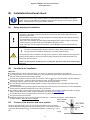
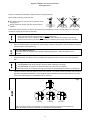
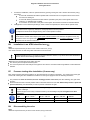
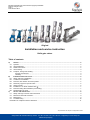
Document: Installation and service instruction (original),”IS-VALVES”
Products: Knife gate valves
Issue: 6
Issue date: 2011-09-12
Original
Installation and service instruction
Knife gate valves
Table of contents
A)
A1
A2
A3
A4
A5
General .................................................................................................................................................................. 2
Symbols ................................................................................................................................................................. 2
Valve destination .................................................................................................................................................... 2
Related documents ................................................................................................................................................ 2
Valve marking ........................................................................................................................................................ 3
Transport, storage and handling............................................................................................................................. 3
Storage and transport ....................................................................................................................................... 3
Handling ............................................................................................................................................................ 3
B)
Installation/functional check ............................................................................................................................... 4
B1 Safety warnings at installation ................................................................................................................................ 4
B2 Conditions for installation ....................................................................................................................................... 4
B3 Pressure, flow direction and valve position ............................................................................................................ 4
B4 Necessary support for special cases...................................................................................................................... 5
B5 Steps to install ........................................................................................................................................................ 5
B6 Installation in an ATEX-classified area .............................................................................................................. 7
B7 Pressure testing after installation (if necessary) ..................................................................................................... 7
B8 Disassembling the valve ........................................................................................................................................ 7
C)
Service and maintenance .................................................................................................................................... 8
C1 Safety warnings at service and maintenance ......................................................................................................... 9
C2 Manual and automatic actuation ............................................................................................................................ 9
C3 Maintenance........................................................................................................................................................... 9
C4 Troubleshooting ................................................................................................................................................... 10
Declaration in compliance with EU-Directives ............................................................................................................... 11
All specifications are subject to change without notice.
Stafsjö Valves AB. SE-618 95 Stavsjö, Sweden. Tel: +46 11 39 31 00. Fax: +46 11 39 30 67. [email protected] www.stafsjo.com
A Bröer Group Company
Original installation and service instruction
Knife gate valves
A)
General
In this instruction a “knife gate valve” is shortly called “valve”.
A1
Symbols
In this instruction notes and warnings are marked with symbols:
Danger / Warning
Points out a dangerous situation which may cause personal injuries or death.
XXXXX
Advice
Has to be respected.
Information
Information useful to follow.
If these notes and warnings are not respected by the user, dangerous situations may occur and may invalidate the
warranty of the manufacturer.
A2
Valve destination
Valve types BV, D2G, HG, HL, HP, JTV, MV, RKO, RKS, SLV, TV, XV and WB are destined – after installation between
flange(s) in a pipe system – to shut off, to open or to control the flow within the admissible pressure/temperature limits.
These pressure and temperature limits depend on the materials of valve body, gate and seat. Temperature limits are
defined in the valve data sheet of each type. Maximum working pressure are marked at the valve body and on the label
attached on the beam.
The flow shall be without vibrations and/or pressure chocks. The surrounding environment should not imply any risk to
the valve. This also implies to explosive environment – except for valves classified for ATEX- area
accordingly.
and marked
Installation of the knife gate valve is preferred with the actuator in an upward position – except for RKO, JTV and D2G.
At valve operation respect:
The manufacturers declaration to EC directives,
This original installation and service instruction which is supplied together with the valve.
Stafsjö Valves AB does not accept any responsibility if this “Valve destination” is not observed.
A3
Related documents
Further information on the valves is available on www.stafsjo.com.
ds+valve type (i.e. ds-BV) = Data sheet with technical information (dimensions, material specification etc.)
mi+valve type (i.e. mi-BV) = Instructions for maintenance on each valve type.
sp+valve type (i.e. sp-BV) = Specify spare parts for each valve type.
acc+type of accessory (i.e. acc-SV) = Accessory for different types of valves. I.e solenoid valve.
stafsjo-valve-spec = Specification of parts and valve combinations.
2
Original installation and service instruction
Knife gate valves
A4
Valve marking
Each valve is labelled as follows:
Additional: Markings on casted valve body:
DN XXXX: (mm) nominal diameter
PN XX:
(bar) pressure class of valve body
i.e. GGG50
valve body material
Max PS Valve
body/differential: 10/10 BAR
Ser.No: Serial number consisting
of year – individual no - order
number.
CE-marking when applicable.
Label for identification of seat and gate material
These labels shall not be removed, over coated or otherwise covered.
“Max. PS Valve body” which is marked on the label (see above) is max. allowed pressure when the valve
is open. Max. allowed pressure on closed valves may be lower and is marked on this label as well.
More information on this is available in the data sheet which can be downloaded from www.stafsjo.com.
Refer to the “Serial Number” of the valve marking at any contact with Stafsjö.
A5 Transport, storage and handling
Note
Additional requirements may be found in the actuator instruction, if any.
Storage and transport:
Keep the valve in open position during storage to ensure its function and to protect the polished surface of the gate.
Store the valve in a clean and dry environment and protect it against dirt, dust and other contamination. Do not expose
the valve to direct sunlight. If the valve is stored outside, it shall be wrapped tightly in a plastic foil or similar to protect it
against moisture or any dirt contamination. It should also be stored high enough without any risk to be covered in snow
or enclosed by water.
The valve has been packed according to the terms of delivery. It is important to make a visual inspection at
arrival. If transport damage is detected, report to the transportation company.
Handling:
Lifting and moving shall be carried out with soft straps. Place and fasten the
soft strap on the valve body as shown in Fig.1. Make shure that all equipment
is designed to hold the weight of the valve.
Never place lifting equipment:
• On the actuator, accessories or gate guards.
• In the bore of the knife gate valve, since it cause damages
to the seat and retainer ring.
3
Fig.1
Original installation and service instruction
Knife gate valves
B)
Installation/functional check
This instruction includes safety recommendations for foreseeable risks at installation into a (pipe)
system. The user is responsible to complete this instruction with warning notes for system-specific
aspects. All requirements of the system shall be observed.
B1
Safety warnings at installation
Installation shall be performed by qualified personal. Qualified are those persons who, due to
experience, can judge the risks and execute the work correctly and who are able to detect and
eliminate possible risks.
After installation, the function of the valve shall be in accordance with the valve and the actuator (if
any) destinations, see section A2.
At the end of the installation the gland bolting shall be tightened according to Table in section B7.
A valve without an actuator should not be installed into the (pipe) system.
Some valve types can be installed as end valves. Contact Stafsjö for specific requirements and
information.
1. A valve with an actuator shall only be operated if:
The valve is installed between flanges or between a flange and a protective device.
The gate guards are installed on the beams on automatic operated valves.
Danger
2. If the knife gate valve is installed as an end valve in a pipe line, always install protective equipment
to prevent people getting to close to the valve and being exposed to the media transported in the
system when the valve opens.
People’s life and health is at stake if this is not observed. Any other action is the responsibility
of the user.
B2
Conditions for installation
Make sure:
To install valves according “Valve destination”, see section A2. Observe valve marking, see section A4.
That the pipe section is not exposed to vibrations or other mechanical stresses which could deform the valve body and
affect the valve‟s tightness and/or ability to operate.
That the valve environment does not imply any risk to the valve, the actuator or the accessories. This also implies to
explosive environment – except for valves classified for ATEX- area and marked accordingly.
That flanges, pipe line and the valve are empty, free from solid and sharp particles.
That the valve is installed between flange(s) (fixed or loose) to ensure that the valve is securely fixed and that the
flange keeps tight.
That the knife gate valve is protected against radiant heat, if the valve is placed near a heat source whose temperature
exceed maximum allowable temperature for the valve or its actuator.
The mating (=gasket contact) surface of the flange cover the retainer ring completely. Detailed information on flange
drilling, threads, length and number of bolts is available in data sheet on www.stafsjo.com.
Those instructions which are supplied with an actuator (if any) will be followed.
The pipe line is free from pressure.
Additional requirements may be found in the actuator instruction – specifically to adjust the correct OPEN and
CLOSED positions before the valve is installed.
SEAT SIDE
B3
Pressure, flow direction and valve position
RKO, RKS
When the knife gate valve is open, P1=P2, the pipe line pressure may not exceed
maximum allowable working pressure body according to each valve. When the valve is
closed, the differential pressure P, is the difference between P1 and P2 ( P = ± (P1P2).
Fig 2
4
SEAT SIDE
MV
P1
P2
Original installation and service instruction
Knife gate valves
The differential pressure P may not exceed maximum allowable differential pressure according to each valve. Maximum
allowable differential pressure for closed valve is available in data sheets.
Valves types XV, HL, HG, HP, BV, WB, D2G and SLV are bi-directional and can therefore be installed independent
of the pressure ratio in any direction in the pipe line.
Valid for MV only:
This valve type has different differential pressure P capacities in the flow directions. The maximum P capacity of
the valve is achieved when the SEAT SIDE is installed as the valve outlet (towards P2) provided that P1 > P2. When
the valve is closed, the pressure ratio shall be P1>P2. Some sizes of MV equipped with specific seats are capable to
handle certain differential pressure in reversed pressure direction. For further information, see data sheets on
www.stafsjo.com.
Valid for RKO and RKS only: These valve types have different differential pressure P capacities in the flow
direction. The maximum P capacity of the valve is achieved when the seat side is installed as the valve inlet
(towards P1) provided that P1>P2. When the valve is closed, the pressure ratio shall be P1>P2.
Valid for TV only:
This valve shall be installed with the seat side to the tank. The removable retainer ring shall be mounted towards the
tank which implies that changing of the seat can only be done when the tank is empty.
All valve types, except for valves D2G, JTV, RKO and RKS are preferred to be installed in a horizontal pipe
(system) with the actuator in a vertical upright position.
Valid for D2G, RKO, JTV and RKS only:
These valve types are designed to be installed in a vertical pipe.
B4
Necessary support for special cases
The dead weight of a valve in large dimension together with its actuator may cause tensions/deformations in the valve
that could affect the valve‟s function, specifically when it is installed at inclined positions or in a vertical pipe. In these
cases, the valve and/or actuator shall be supported to avoid functional failure.
Valves that are exposed to vibrations or other mechanical stresses can be subject to forces that will affect valves
tightness and ability to operate. In these cases, the valves and actuators shall be supported to avoid function failure.
Support details are the responsibility of the customer. Stafsjö will assist on request.
B5
Steps to install
On handwheel operated valves, when the handwheel is not assembled at delivery, follow the steps below to assemble
the handwheel to the valve.
Fig.3 Assembling of handwheel
Handwheel with non-rising
stem
Handwheel with rising-stem
1. Assemble the handwheel to
1. Loosen the nuts from the
2. Assemble the handwheel
the valve. Check that there is
not any play between the
actuator, bearing and yoke. If
there is, eliminate the play by
rotating the stem 360 degrees
counter clockwise. Then fixate
the handwheel with a locking
nut.
tie rods and remove the
tempo-rary yoke plate.
unit to the tie rods and fixate it
with washers and nuts. Attach
the gate clevis to the gate and
fixate with clevis pin and split
pins.
5
3. Remove the safety pin. For
safety reasons, the pin shall
not be removed until the
handwheel unit is assembled
and the gate clevis is
properly attached to the
gate.
Original installation and service instruction
Knife gate valves
When the handwhell is assembled, install the valve into the pipe (system).
Fig 4
When installing the valve, make sure that:
The valve‟s centre line is on the same centre line as the
flanged pipe‟s.
Flange surfaces of the pipe and valve must be exactly
parallel.
If the flanges and the valve are not centred, the valve may be damaged by erosion and a dirt pocket may occur which
can lead to clogging and corrosion of the valve.
Valve type RKO and XV must be installed in closed position only.
Valve type SLV must be installed in open position only! Also note that SLV‟s bottom cover is only
allowed to be mounted on the valve when flushing is made through the purge ports in the valve body.
1.
Place the gaskets between the valve body and the flange. Check that the gasket is well centered and covers the
complete surface of the retainer ring.
Valve types WB and SLV only:
These valve types are equipped with integrated rubber flange gaskets – additional gaskets are not
necessary.
2.
Lubricate the bolts. This allows correct pre-setting of the flange and makes it easier to dismantle the bolting
later.
All Valve types: Flange bolts of right length are necessary:
Too long bolts could deform the valve body and result in leakage in the flange.
Too short bolts could deform the threaded holes in the valve body at installation.
Choose bolts with the correct thread and length according to the flange drilling information in the data sheet.
3.
Tighten the bolts first manually and then evenly and crosswise, for a uniform load of the gasket, with a torque as
required by the gasket manufacturer. Valve type SLV shall be assembled with the mating surfaces of the valve
body and the pipe flanges up to metal/metal contact. See Fig 5.
Fig 5
1=Wrong
2=Wrong
3=Correct
Make sure that the flange is centered and is covering the metal frame around the seat (picture 3).
Tighten flange bolts crosswise to eliminate any gap between body and flange.
6
Original installation and service instruction
Knife gate valves
4.
5.
To finish the installation, make an operational test by opening /closing the valve. Observe the actuator (if any)
instructions.
A valve with handwheel should be operated with normal hand force. Exceptional force used to close
the valve can damage it.
A valve with electric/pneumatic actuator shall be operated by the plant control signals into its end
positions, i.e. OPENED and CLOSED.
At connection of an actuator to the plant control system the actuator„s instructions shall be followed.
If the pipe line is to be cleaned by flushing in order to wash out impurities, the valve must be opened 100%.
Valves with actuator supplied by Stafsjö are exactly adjusted in the end positions:
This adjustment shall not be changed as long as the valve operates correctly.
Only for Valves with electric actuator:
Ensure that the actuator motor stops by the signal of the limit switch of the actuator. Exceptional force may
damage the valve. The signal of the torque switch may be used for signal for faulted conditions. For further
information see the actuator instruction.
B6
Installation in an ATEX-classified area
Note:
Additional requirements may be found in the actuator instruction, (if any).
This ATEX instruction is valid along other instructions in this document.
In ATEX-classified zones, in accordance with ATEX Directive 94/9/EC, only valves with ATEX-classification
and the relevant valve marking shall be installed.
Additional to the requirements above make sure that:
The valve is part of the plants earthed system.
The user has performed a risk analysis of the pipe line and valve in accordance with the guidelines of ATEX Directive
94/9/EC.
B7
Pressure testing after installation (if necessary)
Each Valve has been tested before delivery by the manufacturer according to EN12266-1. For pressure test of the pipe
section with a knife gate valve installed the conditions for the system apply but with the following restrictions:
The pressure test shall not exceed 1,5 x max. working pressure of the valve (see valve marking). The gate shall
be open.
Pressure test with valve in closed position shall not be tested more than 1,1x max. differential pressure in preferred
pressure direction, (see datasheets) in order to prevent overload of the gate.
Immediately at this operation check the stuffing box tightness:
In case of leakage:
Tighten the gland nuts evenly crosswise and bit by bit until leakage stop. Do not tighten more than
necessary!
Recommended maximum torque
DN
DN 50 – DN 80
DN 100 – DN 150
DN 200 – DN 300
> DN 350
20
25
30
35
Nm
Ibf x ft
B8
15
18
22
Disassembling the valve
Note:
Additional requirements may be found in the actuator (if any) instruction.
7
26
Original installation and service instruction
Knife gate valves
For the valve the same safety instructions apply as for the pipe (system) and for the control system to which the actuator
(if any) is connected. The respect of these requirements shall be followed.
Danger
Disassembling the valve from the pipe line may only be done when:
the pipe section is free from pressure and is empty
all the electronic and/or pneumatic/hydraulic connections have been disconnected
People’s life and health is at stake if this is not observed. Any other action is the responsibility of
the user.
Disassemble the valve in following steps:
1. Depressurise the pipe section and drain it completely.
2. Disconnect all electric and/or pneumatic/hydraulic connections.
3. Fasten and use soft straps if necessary (see also Fig.1 in section A5). Make sure not to damage the valve, gate,
gate guards or any accessory.
4. Take out the valve from the pipe carefully in order to protect the flange gaskets.
5. At transport and storage observe section A5.
C)
Service and maintenance
Note
Additional requirements may be found in the actuator instruction.
The user shall make a risk analysis as per Machinery Directive 2006/42/EC for the pipe system. Stafsjö supplies the
following documents for it:
The original installation and service instruction of the valve.
An installation and service instruction of the actuator (if any)
The manufacturer‟s declaration(s) to EC Directives.
This instruction includes safety notes for industrial application for any foreseeable risk at use of the
valve. It is the responsibility of the user/planner to complete this instruction with warning notes for
plantspecific risks.
Further information on Stafsjö‟s valves is available on www.stafsjo.com.
8
Original installation and service instruction
Knife gate valves
C1
Safety warnings at service and maintenance
At operation, the function of the valve shall be in compliance with the <Valve Destination>, see
section A2.
The service conditions of the valve shall be in compliance with the valve markings, see section A4.
Service and maintenance shall be performed by qualified personal. Qualified are those persons
who, due to experience, can judge the risk and execute the work correctly and who are able to
detect and to eliminate possible risks.
At service the valve should be inspected periodically (preferably every day) for leakage or other
external effects that could affect the safety for the personnel.
Valves, destined for use in a ATEX classified zone, must be marked according to the ATEX
directive.
At any start up, the gland box shall be visually inspected for leakage. If any are detected, the nuts
shall be tightened according to table in section B7. Except for this action, no maintenance is allowed
on the valve when the pipe line is pressurised.
At maintenance or repair of an actuator, it shall be disconnected as described in section B8. The
pipe section must be free from pressure and completely drained at both sides of the valve before
any maintenance begins.
Some valve types can be installed as end valves. Contact Stafsjö for specific requirements and
further information.
The temperature of the exterior parts of the valve depends of the fluid temperature inside – any
protective insulation is in the responsibility of the user.
1. The gland box packing together with the gland makes sure that no media reaches surrounding
environment where the gate exit the valve body. When the gland box packing (braids) shall be
changed, the gland bolts must be loosened and the the pipe section shall be depressurised and
empty.
2. A valve with an actuator shall be actuated only if:
The valve is installed between flanges or between a flange and a protective device.
The gate guards are installed on the beams, on automatic operated valves.
Danger
3. If you install the knife gate valve as an end valve in a pipe line, always install protective equipment to
prevent people getting to close to the valve and being exposed to the media transported in the system
when the valve opens.
People’s life and health is at stake if this is not observed. Any other action is the responsibility
of the user.
C2
Manual and automatic actuation
A knife gate valve with handwheel closes clockwise.
A valve with automatic actuator is operated following the signals from the plant control system. Valves equipped with
actuator supplied by Stafsjö are exactly adjusted to stop in the exact end positions. This adjustment shall not be changed
as long as the valve operates correctly.
Valves with infrequent operation:
A test with full actuation movement should be performed once a month, to verify that the valve function correctly.
C3
Maintenance
As long as the valve is tight the only maintenance that has to be performed is a visual control of the stuffing box
tightness. Tighten the gland at any leakage; see section B7 for recommended maximum torque.
9
Original installation and service instruction
Knife gate valves
C4
Troubleshooting
Problem
Leakage from stuffing box
packing
Leakage at
flange connection
Leakage through valve
bore
Gate does not open/close
completely
Gate does not open/close
in a smooth movement
Too large force to
open/close the gate
(too high hand force as
well)
Reason
Gland bolting too loose*
Worn-out box packing
Incorrectly installed box packing
Damaged gate
Wrong length of bolts in flanges
Loose flange bolting
Valve not centred at flange connection
Valve not parallel to flanges
Gasket not centred
Wrong gasket material
Worn-out seat/sealing profile
Valve does not close 100%
Damaged seat or gate
Measure
See relevant maintenance instructions
issued by Stafsjö
Download: www.stafsjo.com
See this instruction, section B7
See Stafsjö‟s maintenance instructions and
relevant data sheet
Download: www.stafsjo.com
See relevant maintenance instructions
issued by Stafsjö
Download: www.stafsjo.com
See instruction for actuator (if any)
See instruction for actuator/accessories
See the relevant maintenance instructions
issued by Stafsjö
Download: www.stafsjo.com
See the relevant instruction for actuator
See relevant maintenance instructions
issued by Stafsjö
Download: www.stafsjo.com
Fault in actuator
Fault in limit switch setting
Valve clogged
Damaged seat/sealing profile or gate
Fault in actuator
Valve clogged
Damaged seat/sealing profile or gate
Not enough air supply pressure
Not enough air flow supply
Gland nuts tightened by too high torque
See the relevant maintenance instructions
Valve exposed to stress/tension
issued by Stafsjö
Download: www.stafsjo.com
Valve clogged or deformed
Damaged seat/gate
* When tightening the gland box bolts: See Table section B7
Stafsjö can offer maintenance of valves. Contact Stafsjö or your local representative for further information.
Stafsjö does not accept any responsibility for the product if wear parts not tested and approved by Stafsjö are used on
the valve. Stafsjö does not accept any responsibility for the product if maintenance instructions are not followed during
maintenance.
10
Original installation and service instruction
Knife gate valves
Declaration in compliance with EU-Directives
The manufacturer Stafsjö Valves AB, SE-618 95 Stavsjö Sweden, declares that valve types BV, D2G, HG, HP, HL, JTV, MV, RKO,
RKS, SLV, TV, XV and WB are manufactured in accordance with the requirements of the following standards and EU-Directives.
EN ISO 12100:2010 ”Safety of machines Basic terms, general design guidelines”
Pressure Equipment Directive 97/23 EC (PED): Art 3 Paragraph 1.3 or Art. 3 Paragraph 3 applies
The valves comply with this directive. The conformity rating procedure used according to Annex III of the Pressure Equipment
Directive 97/23 EG is
For Category II
Module A1
Notified body:
ÅF Kontrol AB SE-60102 Norrköping Reg.-No. 0640
Machine Directive 2006/42 EC (MD) Automatically manoeuvred valves fulfill the demands in this directive as a “partly complete
machine”. This declaration is considered as a declaration of Incorporation. 2006/42/EG does not apply if the valve is actuated
manually – observe the Table below
ATEX Directive 94/9 EC
the directive is fulfilled only when the valve is labelled with CE-marking
The valves comply with this directive. The conformity rating procedure used according to EN13463-5:2003
“Non electric equipment intended for use in potentially explosive atmospheres – Part 5: Protection by con-structional safety “C”
- For Group II, Category 3 G/D
(zone 2 and 22)
Product documents are available on the following:
Design documentation, Technical data sheets, catalogue pages
Stavsjö, 2011-02-08
Thomas Carlson, General Manager
To comply with the directive above, the following applies:
1.
The use of the valve must comply with the <valve destination> defined in the “Original Installation and Service Manual (“IS-VALVES”) supplied
with the valve and must follow all instructions in this manual.
If this manual is not followed, the manufacturer may – in serious cases – be released from his product liability.
2.
The valve shall not be put into operation (and the fitted actuator if any) until the conformity to all applicable EU directives above of the system
into which the valve is fitted has been declared by the persons responsible. A separate declaration is supplied for the actuator named above.
3.
Stafsjö Valves AB has made and documented the required risk analysis; the Stafsjö Valves AB employee responsible for this documentation is
Ulrika Björn, SE-618 95 Stavsjö.
Manufacturer STAFSJÖ Valves AB SE 61895 Stavsjö , Sweden , declares that a STAFSJÖ knife gate valve complies Directives 2006/42/EC as
follows:
Requirements as per Annex 1 of the Directive 2006/42/EC
1.1.1, h) Valve destination
See original installation and service instruction.
1.1.2.,c) foreseeable misuse
See original installation and service instruction, section B1 and C1.
Same as the pipe section into which the valve is installed. See original installation and serviceinstruction section
1.1.2.,d) protecting measures personnel
B1
1.1.2.,e) accessories for maintenance
No special tools are necessary.
All valve material in contact with media are specified in the order acknowledgement and/or on the valve‟s marking.
1.1.3 material in contact with the fluid
The relevant risk analysis is the responsibility of the user.
1.1.5 handling
See original installation and service instruction .
1.2 and 6.2 control system
Is the responsibility of the user in combination with the instruction of the actuator.
For parts under pressure: See declaration of conformity to the PED 97/23/EC.
1.3.2 withstand to stresses
For functional parts: Ensured at contractual use of the valve.
1.3.4 sharp edges or angles
Requirements fulfilled.
Requirements are fulfilled at contractual use of the valve, see original installation and service instruction.
Observe the warnings.
Delivered gate guards must be installed on the valve.
1.3.7/.8 risks related to moving parts
No maintenance is allowed when the pipe line is pressurized or the automatic actuator is connected.
If the valve is modified by the customer (new actuator) necessary protective devices shall be installed. Ask Stafsjö
for support.
1.5.1 – 1.5.3 energy supply
In the responsibility of the user in combination with the instruction of the actuator.
1.5.5 contact to surface with high/low
See warning in the Original installation and service instruction.
temp.
-protection may be necessary. This shall be confirmed in Stafsjö‟s order acknowledgement. Observe the
1.5.7 -explosion
valve‟s marking and relevant instruction from Stafsjö.
Not applicable at not dangerous fluids.
1.5.13 emission of dangerous
For dangerous fluids: pay attention when re-tightening the gland box. Personal safety equipment may be
substances
necessary.
1.6. maintenance
See original installation and service instruction.
Knife gate valve: see original installation and service instruction.
1.7.3 marking
Actuator: see actuator instruction.
1.7.4 service instruction
See original installation and service instruction and actuator instruction.
Requirements from Annex III
The knife gate valve is not a complete machine. No CE marking for conformity with the directive 2006/42/EG.
Requirements from Annexes IV,VIII to
Not applicable.
XI
11