1
Support: http://www.jcmglobal.com/en/contact/default.aspx
Website: http://www.jcmglobal.com
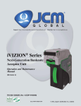
iVIZION® Series
Next-Generation Banknote
Acceptor Unit
Operation and Maintenance
Manual
(Revision 5)
P/N 960-100929R_Rev. 5 {EDP #148849}
Issue #4074-SME-01-05
© 2014, JAPAN CASH MACHINE CO., LTD.
iVIZION® Series Next-Generation Banknote Acceptor Unit Operation and Maintenance Manual
Issue #4074-SME-01-05
REVISION HISTORY
Rev №.
Date
Reason for Update
Comment
A
1-06-11
1
3-1-11
Section 7 Parts List Number Changes incorporated.
Engineering
dictated changes
2
7-11-11
Additional Section 7 Parts List Number Changes incorporated and LD Version information added.
Engineering
dictated changes
3
1-25-12
Added Specifications, installation information and Graphics
regarding the iVIZION LD Version Unit.
Engineering
dictated changes
4
10-12-12
Minor changes & corrections made in Sections 2, 6, 7 & A.
Engineering
dictated changes
5
6-17-14
Added SH Specification Cash Box information in Section 1, 4
and 7.
Engineering
dictated changes
Initial Version
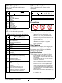
International Compliance
• RoHS Directives
• UL & c-UL Marks
or
or
or
File No. E142330, Subscriber 857947001, Vo.2
• CE Mark
• CB Scheme NO58326
• FCC & IC Directives
See Below.
Contains Transmitter Module
FCC ID: VZQNRWA3
MODEL NO.: NRWA3
IC: 8285A-NRWA3
This device complies with Part 15 of FCC Rules and RSS-Gen of IC Rules. Operation is subject to the following two conditions:
(1) this device may not cause interference, and (2) this device must accept any interference, including interference that may
cause undesired operation of this device.
FCC WARNING
Changes or modifications not expressly approved by the party responsible for compliance could void the user’s authority to
operate the equipment.
FCC NOTICE
This equipment has been tested and found to comply with the limits for a Class A digital device, pursuant to part 15 of the FCC
Rules. These limits are designed to provide reasonable protection against harmful interference when the equipment is operated
in a commercial environment.
This equipment generates, uses and can radiate radio frequency energy and, if not installed and used in accordance with the
instructions, may cause harmful interference to radio communications. Operation of this equipment in a residential area is likely
to cause harmful interference in which case the user will be required to correct the interference at his own expense.
IC NOTICE
This class A digital apparatus complies with Canadian ICES-003.
Cet appareil numerique de la classe A est conforme a la norme NMB-003 du Canada.
Copyright © 2014 By JAPAN CASH MACHINE CO., LTD.
This product document (hereinafter referred to as “Manual”) is fully covered by legal Copyrights owned by the JAPAN
CASH MACHINE CO., LTD. (hereinafter referred to as “JCM”) under Japanese laws and foreign countries. This Manual
contains many copyrighted, patented or properly registered equipment items manufactured by JCM, that are prohibited
and illegal to duplicate, replicate, or copy in whole, or in part, without the express authorization by JCM with the following
exceptions:
1. When an authorized JCM agency or distributor duplicates the Manual for sales promotion and/or service
maintenance of the product, or technical service personnel education as required; and
2. When an end user duplicates the Manual to maintain operation of the product or operate the product in general.
JCM retains all rights to amend, alter, change or delete any portion of this Manual in whole, or in part, or add items
thereto without notice regarding the product or its related products.
JCM is a registered trademark of JAPAN CASH MACHINE CO., LTD. All other product names mentioned herein may be
registered trademarks or trademarks of their respective companies. Furthermore, ™, ® and © are not always mentioned
in each case throughout this publication.
iVIZION® Series
Next-Generation Banknote Acceptor Unit
Table of Contents
Page
1 GENERAL INFORMATION ................................................................................. 1-1
Description .................................................................................................................. 1-1
iVIZION Units ............................................................................................................... 1-1
Model Descriptions .................................................................................................... 1-1
Type Descriptions ....................................................................................................... 1-2
Software Descriptions ................................................................................................ 1-2
Precautions ................................................................................................................. 1-2
User Cautions ............................................................................................................. 1-2
Installation Cautions .................................................................................................................1-2
Mounting, Dismounting & Transportation .................................................................................1-3
Preventive Maintenance ...........................................................................................................1-3
Banknote Fitness Requirements ..............................................................................................1-3
Reference Paper Use Precautions ...........................................................................................1-4
Primary Features ........................................................................................................ 1-4
Component Names ..................................................................................................... 1-5
Specifications (iVIZION SS/SH Specifications) ........................................................ 1-6
Technical Specifications ..........................................................................................................1-6
Environmental Specifications ...................................................................................................1-7
Electrical Specifications ............................................................................................................1-7
Structural Specifications ...........................................................................................................1-7
Specifications (iVIZION LD Specifications) .............................................................. 1-8
Technical Specifications ...........................................................................................................1-8
Environmental Specifications ...................................................................................................1-9
Electrical Specifications ............................................................................................................1-9
Structural Specifications ...........................................................................................................1-9
iVIZION SS Entire Unit Outside Dimensions .......................................................... 1-10
iVIZION SH Entire Unit Outside Dimensions .......................................................... 1-11
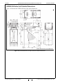
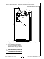
iVIZION SS/SH Installation/Maintenance Space Requirements ............................ 1-12
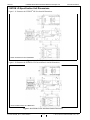
iVIZION LD Specification Unit Dimensions ............................................................ 1-14
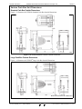
Various Cash Box Unit Dimensions ........................................................................ 1-15
Standard Cash Box Outside Dimensions ...............................................................................1-15
Large Cash Box Outside Dimensions ....................................................................................1-15
HC Cash Box Outside Dimensions ........................................................................................1-16
Technical Contact Information ................................................................................ 1-17
Americas ................................................................................................................................1-17
JCM American .....................................................................................................................1-17
Europe, Africa, Russia & Middle East ....................................................................................1-17
JCM Europe GmbH .............................................................................................................1-17
UK & Ireland ...........................................................................................................................1-17
JCM Europe (UK Office) ......................................................................................................1-17
Asia and Oceania ...................................................................................................................1-17
JCM Gold (HK) Ltd. .............................................................................................................1-17
JAPAN CASH MACHINE CO., LTD. (HQ) ...........................................................................1-17
2 INSTALLATION .................................................................................................. 2-1
Installation Process ..................................................................................................................2-1
P/N 960-100929R_Rev. 5 {EDP #148849}
i
© 2014, JAPAN CASH MACHINE CO., LTD.
iVIZION® Series Next-Generation Banknote Acceptor Unit
Table of Contents
Page
Cable Interconnection ................................................................................................ 2-2
Lock Installation ......................................................................................................... 2-2
Unlock Procedure .................................................................................................................... 2-2
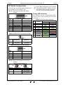
DIP Switch Configurations ........................................................................................ 2-3
Primary LED Indications .......................................................................................................... 2-3
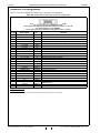
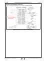
Connector Pin Assignments ..................................................................................... 2-4
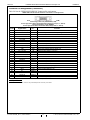
Connector Pin Assignments (Continued 1)
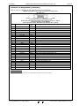
Connector Pin Assignments (Continued 2)
Connector Pin Assignments (Continued 3)
Connector Pin Assignments (Continued 4)
Connector Pin Assignments (Continued 5)
.............................................................................. 2-5
.............................................................................. 2-6
.............................................................................. 2-7
.............................................................................. 2-8
.............................................................................. 2-9
Preventive Maintenance .......................................................................................... 2-10
Retrieving Banknotes ............................................................................................................. 2-10
Clearing a Banknote Jam ...................................................................................................... 2-10
Cleaning Procedure ................................................................................................. 2-10
Sensor Cleaning Procedure ................................................................................................... 2-10
iVIZION Optional LD Version Unit Installation ........................................................2-11
iVIZION Sensor Locations ....................................................................................... 2-12
Standard Interface Circuit Schematics ................................................................... 2-13
Interface Circuit Schematics (Continued 1) ........................................................................... 2-14
Interface Circuit Schematics (Continued 2) ........................................................................... 2-15
Interface Circuit Schematics (Continued 3) ........................................................................... 2-16
Operational Flowchart ............................................................................................. 2-17
Operational Flowchart (Continued 1) ..................................................................................... 2-18
Operational Flowchart (Continued 2) ..................................................................................... 2-19
3 COMMUNICATIONS ........................................................................................... 3-1
Americas ..................................................................................................................... 3-1
JCM American ......................................................................................................................... 3-1
Europe, Africa, Russia & Middle East ...................................................................... 3-1
JCM Europe GmbH ................................................................................................................. 3-1
UK & Ireland ................................................................................................................ 3-1
JCM Europe (UK Office) .......................................................................................................... 3-1
Asia and Oceania ....................................................................................................... 3-1
JCM Gold (HK) Ltd. .................................................................................................................. 3-1
JAPAN CASH MACHINE CO., LTD. (HQ) ............................................................................... 3-1
4 DISASSEMBLY/REASSEMBLY ......................................................................... 4-1
Tool Requirements ..................................................................................................... 4-1
Pusher Unit Timing Belt Removal ............................................................................. 4-1
iVIZION Standard and Large Cash Box ................................................................................... 4-1
iVIZION HC Cash Box ............................................................................................................. 4-3
Home Position Sensor Board/Home Position Sensor, FFC & Interface
Connector Board Removals ...................................................................................... 4-5
RFID Module & Harness Removals ........................................................................... 4-6
Validation CPU & Controller CPU Board Removals ................................................ 4-6
USB FPC, Power FPC & Interface FPC Cable Removals ........................................ 4-7
Validation Unit Harness Removal ............................................................................. 4-7
Interrupter Board Removal ........................................................................................ 4-8
P/N 960-100929R_Rev. 5 {EDP #148849}
ii
© 2014, JAPAN CASH MACHINE CO., LTD.
iVIZION® Series Next-Generation Banknote Acceptor Unit
Table of Contents
Page
Motor Unit Timing Belt Removal ............................................................................... 4-8
Stacker Motor & Transport Motor Removals ............................................................ 4-8
Bezel Retainer Clips A & B Removal ........................................................................ 4-9
Sensor Transfer Board/CIS FFC/Transmissive Light FFC & Upper UV FPC
Sensor Removals ....................................................................................................... 4-9
Validation Sensor Board Assembly Removal ........................................................ 4-10
Validation Sensor FPC Cable Removals ................................................................ 4-10
CIS/Transmissive Light & Upper UV Sensor Removals ........................................ 4-11
CIS/CIS FPC/Lower UV Sensor & Lower UV FFC Removal .................................. 4-12
Validation Unit Timing Belt Removal ...................................................................... 4-13
Reassembly Cautions .............................................................................................. 4-13
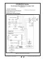
5 WIRING DIAGRAMS ........................................................................................... 5-1
iVIZION System Wiring Diagram ............................................................................... 5-1
6 PERFORMANCE TESTS .................................................................................... 6-1
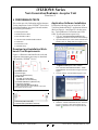
Download and Installation Workbench Tool Requirements ................................... 6-1
Application Software Installation .............................................................................. 6-1
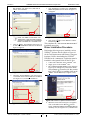
Driver Installation Procedure .................................................................................... 6-2
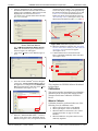
JCM Tool Suite Standard Edition Mode .................................................................... 6-3
Software Download Tool Requirements ...................................................................................6-4
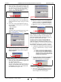
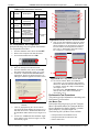
Software Download Procedures ............................................................................... 6-4
Download the Upgrade Program ...........................................................................................6-4
Downloading the Program First Time ....................................................................................6-5
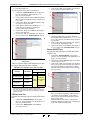
Calibration ................................................................................................................... 6-6
When to Calibrate .....................................................................................................................6-6
Calibration Order ...................................................................................................................6-7
Calibration Tool Requirements .................................................................................................6-7
Reference Paper Placement ....................................................................................................6-7
Placing the KS-072/KS-089 Reference Paper .......................................................................6-7
Calibration Procedure ...............................................................................................................6-8
Calibration Only .....................................................................................................................6-8
Calibration Plus Serial Number Writing ................................................................................6-10
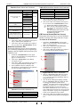
Performance Tests .................................................................................................... 6-11
Performance Test Tool Requirement using a PC ................................................................... 6-11
Performance Test Items using a PC ....................................................................................... 6-11
PC Performance Test Preparation ..........................................................................................6-12
Performance Test Procedures ................................................................................................6-12
Any Motor Test .....................................................................................................................6-12
LED Indicator Test ...............................................................................................................6-13
Sensor ON/OFF Test ...........................................................................................................6-13
Banknote Acceptance Test ..................................................................................................6-14
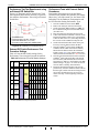
ICB Function Setting (Barcode Coupon) .............................................................................6-14
DIP Switch ON/OFF Test .....................................................................................................6-15
Performance Test Tool Requirement using an External DIP Switch Box ...............................6-16
External DIP Switch Performance Test Procedure Settings ...................................................6-16
Performance Tests with External Switch Procedures .............................................................6-16
iVIZION Utility Tools ................................................................................................. 6-17
ICB/Image Setting Tool Requirements ...................................................................................6-17
ICB/Image Setting Change Preparation .................................................................................6-17
P/N 960-100929R_Rev. 5 {EDP #148849}
iii
© 2014, JAPAN CASH MACHINE CO., LTD.
iVIZION® Series Next-Generation Banknote Acceptor Unit
Table of Contents
Page
CIS Image Tool ...................................................................................................................... 6-17
ICB Function Setting .............................................................................................................. 6-18
Setting ICB Enable/Disable Functions ................................................................................ 6-18
ICB Function Operational Condition ...................................................................................... 6-20
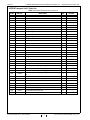
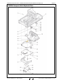
7 EXPLODED VIEWS & PARTS LISTS ................................................................. 7-1
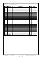
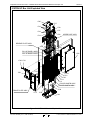
iVIZION Entire Unit View ............................................................................................ 7-1
iVIZION Entire Unit Parts List .................................................................................................. 7-2
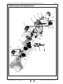
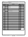
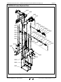
iVIZION Validation Unit 1 Exploded View ................................................................. 7-3
iVIZION Validation Unit 1 Parts List ......................................................................................... 7-4
iVIZION Validation Unit 2 Exploded View ................................................................. 7-5
iVIZION Validation Unit 2 Parts List ......................................................................................... 7-6
iVIZION Validation Unit 3 Exploded View ................................................................. 7-7
iVIZION Validation Unit 3 Parts List ......................................................................................... 7-8
iVIZION Transport Unit 1 Exploded View .................................................................. 7-9
iVIZION Transport Unit 1 Parts List ....................................................................................... 7-10
iVIZION Transport Unit 2 Exploded View .................................................................7-11
iVIZION Transport Unit 2 Parts List ....................................................................................... 7-12
iVIZION Transport Unit 3 Exploded View ................................................................ 7-13
iVIZION Transport Unit 3 Parts List ....................................................................................... 7-14
iVIZION Transport Unit 4 Exploded View ................................................................ 7-15
iVIZION Transport Unit 4 Parts List ....................................................................................... 7-16
iVIZION Transport Unit 5 Exploded View ................................................................ 7-17
iVIZION Transport Unit 5 Parts List ....................................................................................... 7-18
iVIZION Transport Unit 6 Exploded View ................................................................ 7-19
iVIZION Transport Unit 6 Parts List ....................................................................................... 7-20
iVIZION SS Version Frame Unit Exploded View ..................................................... 7-21
iVIZION SS Version Frame Unit Parts List ............................................................................. 7-22
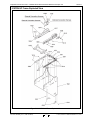
iVIZION Cash Box Unit 1 Exploded View ................................................................ 7-23
iVIZION Cash Box Unit 1 Parts List ....................................................................................... 7-24
iVIZION Cash Box Unit 2 Exploded View ................................................................ 7-25
iVIZION Cash Box Unit 2 Parts List ....................................................................................... 7-26
iVIZION Cash Box Unit 3 Exploded View ................................................................ 7-27
iVIZION Cash Box Unit 3 Parts List ....................................................................................... 7-28
iVIZION LD Frame Exploded View ........................................................................... 7-29
iVIZION LD Frame Parts List ................................................................................................. 7-30
iVIZION HC Frame Exploded View .......................................................................... 7-31
iVIZION HC Frame Parts List ................................................................................................. 7-32
iVIZION HC Box Assembly Exploded View ............................................................ 7-33
iVIZION HC Box Assembly Parts List .................................................................................... 7-34
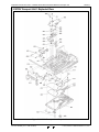
iVIZION HC Box Unit Exploded View ...................................................................... 7-35
iVIZION HC Box Unit Parts List ............................................................................................. 7-36
iVIZION HC Upper Part Exploded View ................................................................... 7-37
iVIZION HC Upper Part Parts List .......................................................................................... 7-38
iVIZION HC Receive Plate Assembly Exploded View ............................................ 7-39
iVIZION HC Receive Plate Assembly Parts List .................................................................... 7-40
iVIZION HC Receive Spring Base Assembly Exploded View ............................... 7-41
iVIZION HC Receive Spring Base Assembly Parts List ......................................................... 7-42
P/N 960-100929R_Rev. 5 {EDP #148849}
iv
© 2014, JAPAN CASH MACHINE CO., LTD.
iVIZION® Series Next-Generation Banknote Acceptor Unit
Table of Contents
Page
iVIZION HC Front Plate Assembly Exploded View ................................................ 7-43
iVIZION HC Front Plate Assembly Parts List .........................................................................7-44
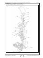
iVIZION HC Pusher Unit Exploded View ................................................................. 7-45
iVIZION HC Pusher Unit Parts List .........................................................................................7-46
iVIZION HC Pusher Assembly 1 Exploded View .................................................... 7-47
iVIZION HC Pusher Assembly 1 Parts List ............................................................................7-48
iVIZION HC Pusher Assembly 2 Exploded View .................................................... 7-49
iVIZION HC Pusher Assembly 2 Parts List ............................................................................7-50
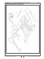
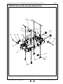
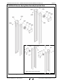
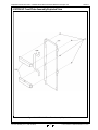
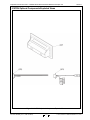
iVIZION Optional Components Exploded Views .................................................... 7-51
iVIZION Optional Components Parts List ..............................................................................7-52
8 INDEX .................................................................................................................. 8-1
A TROUBLESHOOTING ........................................................................................A-1
Introduction .................................................................................................................A-1
Troubleshooting Overview ........................................................................................A-1
Malfunction LED Error Codes ...................................................................................A-1
LED Indication Conditions .........................................................................................A-1
Error, Jam and Reject Code Tables ..........................................................................A-2
LED Error Codes ..................................................................................................................... A-2
Jam Error Codes ..................................................................................................................... A-4
Reject Error Code .................................................................................................................... A-5
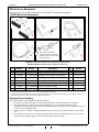
Maintenance Equipment ............................................................................................A-6
iVIZION Maintenance Equipment ............................................................................................ A-6
Reference Paper Handling ...................................................................................................... A-6
B GLOSSARY .........................................................................................................B-1
P/N 960-100929R_Rev. 5 {EDP #148849}
v
© 2014, JAPAN CASH MACHINE CO., LTD.
iVIZION® Series Next-Generation Banknote Acceptor Unit Table of Contents
THIS PAGE INTENTIONALLY LEFT BLANK
P/N 960-100929R_Rev. 5 {EDP #148849}
vi
© 2014, JAPAN CASH MACHINE CO., LTD.
iVIZION® Series
Next-Generation Banknote Acceptor Unit
List of Figures
Page
Figure 1-1
Figure 1-2
Figure 1-3
Figure 1-4
Figure 1-5
Figure 1-6
Figure 1-7
Figure 1-8
Figure 1-9
Figure 1-10
Figure 1-11
Figure 1-12
Figure 1-13
Figure 1-14
Figure 1-15
Figure 2-1
Figure 2-2
Figure 2-3
Figure 2-4
Figure 2-5
Figure 2-6
Figure 2-7
Figure 2-8
Figure 2-9
Figure 2-10
Figure 2-11
Figure 2-12
Figure 2-13
Figure 2-14
Figure 2-15
Figure 2-16
Figure 2-17
Figure 2-18
Figure 2-19
Figure 2-20
Figure 2-21
Figure 2-22
iVIZION Unit .......................................................................................... 1-1
Precautionary Symbols ......................................................................... 1-2
Unacceptable Banknotes ...................................................................... 1-3
Reference Paper Handling Precautions ............................................... 1-4
iVIZION Component Names ................................................................. 1-5
iVIZION Banknote Acceptor SS Unit Outside Dimensions ................. 1-10
iVIZION Banknote Acceptor SH Unit Outside Dimensions ................. 1-11
iVIZION SS Unit Installation and Maintenance Space
Requirements Diagram ....................................................................... 1-12
Maximum Gradient Angle = 50 Degrees ............................................. 1-12
iVIZION SH Unit Installation and Maintenance Space
Requirements Diagram ....................................................................... 1-13
iVIZION LD Unit Outside Dimensions ................................................. 1-14
iVIZION LD Unit with Bezel Outside Dimensions ............................... 1-14
iVIZION Standard Cash Box Outside Dimensions .............................. 1-15
iVIZION Large Cash Box Outside Dimensions ................................... 1-15
iVIZION HC Cash Box Outside Dimensions ....................................... 1-16
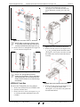
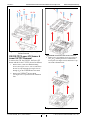
Interface Harness Installation Location ................................................. 2-1
M4 Screws Locations (Left/Right Side) ................................................. 2-1
Flat Head Screws Locations (Rear Side) .............................................. 2-1
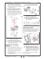
Cable Interconnection ........................................................................... 2-2
Lock Size .............................................................................................. 2-2
Unlock Rotation Direction ..................................................................... 2-2
Key Cap Installation .............................................................................. 2-2
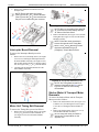
Retrieving Banknote ........................................................................... 2-10
Open the Upper Guides ...................................................................... 2-10
Retrieving Cash Box Banknote Jam ................................................... 2-10
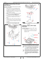
Interface Harness Installation Location ............................................... 2-11
M3 Screws Locations .......................................................................... 2-11
iVIZION Sensor Cleaning Locations ................................................... 2-12
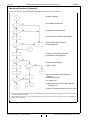
iVIZION USB Circuit Interface Schematic Diagram ............................ 2-13
iVIZION Photo-Coupler Circuit Interface Schematic Diagram ............ 2-13
iVIZION RS232C Circuit Interface Schematic Diagram ...................... 2-14
iVIZION ccTalk Circuit Interface Schematic Diagram ......................... 2-14
iVIZION TTL Circuit Interface Schematic Diagram ............................. 2-15
iVIZION LED Circuit Interface Schematic Diagram ............................ 2-16
iVIZION SS/LD Banknote Acceptor Operational Flowchart
(Initializing) .......................................................................................... 2-17
iVIZION SS Banknote Acceptor Operational Flowchart
(Part 1 - Validating) ............................................................................. 2-18
iVIZION LD Banknote Acceptor Operational Flowchart
(Part 2 - Validating) ............................................................................. 2-19
P/N 960-100929R_Rev. 5 {EDP #148849}
vii
© 2014, JAPAN CASH MACHINE CO., LTD.
iVIZION® Series Next-Generation Banknote Acceptor Unit
List of Figures
Page
Figure 4-1
Figure 4-2
Figure 4-3
Figure 4-4
Figure 4-5
Figure 4-6
Figure 4-7
Figure 4-8
Figure 4-9
Figure 4-10
Figure 4-11
Figure 4-12
Figure 4-13
Figure 4-14
Figure 4-15
Figure 4-16
Figure 4-17
Figure 4-18
Figure 4-19
Figure 4-20
Figure 4-21
Figure 4-22
Figure 4-23
Figure 4-24
Figure 4-25
Figure 4-26
Figure 4-27
Figure 4-28
Figure 4-29
Figure 4-30
Figure 4-31
Figure 4-32
Figure 4-33
Figure 4-34
Figure 4-35
Figure 4-36
Figure 4-37
Figure 4-38
Figure 4-39
Figure 4-40
Figure 4-41
Figure 4-42
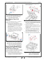
Pusher Mechanism Screws Removal ................................................... 4-1
Pusher Mechanism Removal ................................................................ 4-1
Pusher Mechanism Cover Removal ...................................................... 4-2
Stacker Guide Removal ........................................................................ 4-2
Stacker Guide Reassembly ................................................................... 4-2
Right Frame Outer “R” Removal ........................................................... 4-2
Left Frame Outer “L” Removal .............................................................. 4-3
Timing Belt Removal ............................................................................. 4-3
Pusher Mechanism Removal ................................................................ 4-3
HC Box Stacker Base Removal ............................................................ 4-3
Pusher Guide Removal ......................................................................... 4-4
Stacker Guide Removal ........................................................................ 4-4
Stacker Guide Reassembly ................................................................... 4-4
Outer Guide R Removal 1 ..................................................................... 4-4
Outer Guide R Removal 2 ..................................................................... 4-4
Outer Guide L Removal 1 ..................................................................... 4-5
Outer Guide L Removal 2 ..................................................................... 4-5
Timing Belt Removal ............................................................................. 4-5
TR Bottom Cover Removal ................................................................... 4-5
TR Side Cover “A” Removal .................................................................. 4-6
Home Position Sensor Board, Home Position Sensor FFC Assembly
and Interface Connector Board Removals ............................................. 4-6
RFID Module & Harness Removal ........................................................ 4-6
CPU Board Module Removal ................................................................ 4-6
Extension Memory Board Removal ....................................................... 4-7
Validation CPU Board and Control CPU Board Removal ...................... 4-7
Motor Module Removal ......................................................................... 4-7
USB FPC, Power FPC & Interface FPC Cable Removal ....................... 4-7
Validation Unit Harness Removal ......................................................... 4-8
Interrupter Board Removal .................................................................... 4-8
Timing Belt Removal ............................................................................. 4-8
Timing Belt Reassembly Path ............................................................... 4-8
Stacker & Transport Motor Removal ..................................................... 4-9
Bezel Retainer Chips A&B Removal ..................................................... 4-9
Upper Cover Removal ........................................................................... 4-9
Sensor Transfer Board Assembly, CIS FFC, Transmissive Light &
Upper UV FPC Cable Removal.............................................................. 4-9
iVIZION Head Cover A Removal ......................................................... 4-10
Validation Sensor Board Assembly Removal....................................... 4-10
Validation Sensor FPC Removal ......................................................... 4-10
Validation Sensor FPC Reassembly ................................................... 4-11
Upper Validation Part Removal ........................................................... 4-11
iVIZION Head BG85B Removal .......................................................... 4-11
CIS, Transmissive Light & Upper UV Sensor Removal ....................... 4-12
P/N 960-100929R_Rev. 5 {EDP #148849}
viii
© 2014, JAPAN CASH MACHINE CO., LTD.
iVIZION® Series Next-Generation Banknote Acceptor Unit
List of Figures
Page
Figure 4-43
Figure 4-44
Figure 4-45
Figure 4-46
Figure 4-47
Figure 4-48
Figure 5-1
Figure 6-1
Figure 6-2
Figure 6-3
Figure 6-4
Figure 6-5
Figure 6-6
Figure 6-7
Figure 6-8
Figure 6-9
Figure 6-10
Figure 6-11
Figure 6-12
Figure 6-13
Figure 6-14
Figure 6-15
Figure 6-16
Figure 6-17
Figure 6-18
Figure 6-19
Figure 6-20
Figure 6-21
Figure 6-22
Figure 6-23
Figure 6-24
Figure 6-25
Figure 6-26
Figure 6-27
Figure 6-28
Figure 6-29
Figure 6-30
Figure 6-31
Figure 6-32
Figure 6-33
Figure 6-34
Figure 6-35
Figure 6-36
Figure 6-37
iVIZION BG 85A HEAD Removal ........................................................4-12
Lower Validation Part Removal ...........................................................4-12
CIS, CIS FPC, Lower UV Sensor & Lower UV FFC Removal ..............4-13
Timing Belt Removal ...........................................................................4-13
Timing Belt Replacement ....................................................................4-13
Upper/Lower UV Sensors Location .....................................................4-13
iVIZION System Wiring Diagram ...........................................................5-1
Tool and Harness Connections .............................................................6-1
USB Cable Type Requirement ..............................................................6-1
Setup.exe File Location .........................................................................6-1
Install Shield Wizard Screen ..................................................................6-1
Customer Information Screen ................................................................6-2
Destination Folder Screen .....................................................................6-2
Current Settings Confirmation ...............................................................6-2
Installation Completion Screen ..............................................................6-2
Hardware Update Wizard Screen 1 .......................................................6-2
Hardware Update Wizard Screen 2 .......................................................6-3
Hardware Update Wizard Screen 3 .......................................................6-3
Hardware Update Wizard Screen 4 .......................................................6-3
Normal Mode Selection .........................................................................6-3
Test Mode Selection ..............................................................................6-3
Required Software Download Tools ......................................................6-4
DIP Switches All OFF ............................................................................6-4
JCM Tool Suite Standard Edition Screen ............................................. 6-4
JCM Tool Suite Standard Edition Screen Pull-Down Menu .................. 6-4
Browse Screen Button Location ............................................................6-4
iVIZION Software Program Selection ................................................... 6-5
Download Progress Screen 1 ................................................................6-5
Download Completed Screen 1 .............................................................6-5
DIP Switches 6, 7, & 8 ON ....................................................................6-5
JCM Tool Suite Standard Edition Screen 2 ............................................6-5
JCM Tool Suite Standard Edition Screen Pull-Down Menu 2.................6-6
Browse Screen Button Location ............................................................6-6
iVIZION Software Program Selection ....................................................6-6
Download Progress Screen 2 ................................................................6-6
Download Completed Screen 2 .............................................................6-6
Remote Calibration Tools Required ......................................................6-7
KS-072/KS-089 Reference Paper .........................................................6-7
Reference Paper Setting 1 ....................................................................6-7
Reference Paper Setting 2 ....................................................................6-8
DIP Switch #8 ON ..................................................................................6-8
JCM Tool Suite Standard Edition Screen 3 ............................................6-8
iVIZION Calibration Ver.X.XX Screen ...................................................6-8
Feed-Out Calibration Proceeding Screen...............................................6-8
P/N 960-100929R_Rev. 5 {EDP #148849}
ix
© 2014, JAPAN CASH MACHINE CO., LTD.
iVIZION® Series Next-Generation Banknote Acceptor Unit
List of Figures
Page
Figure 6-38
Figure 6-39
Figure 6-40
Figure 6-41
Figure 6-42
Figure 6-43
Figure 6-44
Figure 6-45
Figure 6-46
Figure 6-47
Figure 6-48
Figure 6-49
Figure 6-50
Figure 6-51
Figure 6-52
Figure 6-53
Figure 6-54
Figure 6-55
Figure 6-56
Figure 6-57
Figure 6-58
Figure 6-59
Figure 6-60
Figure 6-61
Figure 6-62
Figure 6-63
Figure 6-64
Figure 6-65
Figure 6-66
Figure 6-67
Figure 6-68
Figure 6-69
Figure 6-70
Figure 6-71
Figure 6-72
Figure 6-73
Figure 6-74
Figure 6-75
Figure 6-76
Figure 6-77
Figure 6-78
Figure 6-79
Figure 6-80
Figure 6-81
Calibration Information Screen 1 ........................................................... 6-8
Calibration Information Screen 2 ........................................................... 6-9
Pusher Plate Release Location ............................................................. 6-9
Cardboard Setting Location .................................................................. 6-9
Exit Calibration Proceeding Screen ...................................................... 6-9
Calibration Information Screen 3 ........................................................... 6-9
UV Calibration Proceeding Screen ....................................................... 6-9
Calibration Information Screen 4 ........................................................... 6-9
Calibration Information Screen 5 ......................................................... 6-10
CIS Calibration Proceeding Screen .................................................... 6-10
Calibration Information Screen 6 ......................................................... 6-10
Calibration Value Writing Screen ........................................................ 6-10
Calibration Complete Screen .............................................................. 6-10
iVIZION Calibration Service Suite Edition Screen................................ 6-10
Setting Manufacture No. Screen ......................................................... 6-11
Calibration Value Writing Screen ........................................................ 6-11
Adjustment Info Screen ....................................................................... 6-11
PC Performance Test Tools Required ................................................ 6-11
DIP Switch #8 Set ON ......................................................................... 6-12
JCM Tool Suite Standard Edition Screen............................................. 6-12
iVIZION Test Item VerX.XX Screen .................................................... 6-12
Start, Stop & Exit Screen Button ......................................................... 6-12
Transport Motor Normal Forward Test Screen .................................... 6-13
LED Indicator Test Screen .................................................................. 6-13
Sensor ON/OFF Test Screen .............................................................. 6-13
Denomination Indication Location ....................................................... 6-14
ICB Function Test Screen ................................................................... 6-14
DIP Switch ON/OFF Test Screen 1 ..................................................... 6-15
DIP Switch ON/OFF Test Screen 2 ..................................................... 6-15
Calibration Tool Requirements ............................................................ 6-16
ICB Setting Tool Requirements ........................................................... 6-17
JCM Tool Suite Standard Edition ........................................................ 6-17
iVIZION Utility Tool Version X.XX for Suite Edition Screen 1 .............. 6-17
Empty CIS IMAGE Screen .................................................................. 6-17
Last Acceptance CIS IMAGE Screen .................................................. 6-18
iVIZION Utility Tool Version X.XX for Suite Edition Screen 2 ............. 6-18
ICB Function Screen ........................................................................... 6-18
Enable Setting Completion .................................................................. 6-18
Disable Setting Completion ................................................................. 6-19
ICB Current Status Screen .................................................................. 6-19
Machine Number Setting ..................................................................... 6-19
Machine Number Setting Completion ................................................. 6-19
Machine Number Indication ................................................................ 6-19
Inhibit Screen Button Location ............................................................ 6-19
P/N 960-100929R_Rev. 5 {EDP #148849}
x
© 2014, JAPAN CASH MACHINE CO., LTD.
iVIZION® Series Next-Generation Banknote Acceptor Unit
List of Figures
Page
Figure 6-82
Figure 6-83
Figure 7-1
Figure 7-2
Figure 7-3
Figure 7-4
Figure 7-5
Figure 7-6
Figure 7-7
Figure 7-8
Figure 7-9
Figure 7-10
Figure 7-11
Figure 7-12
Figure 7-13
Figure 7-14
Figure 7-15
Figure 7-16
Figure 7-17
Figure 7-18
Figure 7-19
Figure 7-20
Figure 7-21
Figure 7-22
Figure 7-23
Figure 7-24
Figure 7-25
Figure 7-26
Figure A-1
Inhibit Setting Completion ....................................................................6-20
ICB System Status Indication ..............................................................6-20
iVIZION Entire Unit View .......................................................................7-1
iVIZION Validation Unit 1 Exploded View ..............................................7-3
iVIZION Validation Unit 2 Exploded View ..............................................7-5
iVIZION Validation Unit 3 Exploded View ..............................................7-7
iVIZION Transport Unit 1 Exploded View ..............................................7-9
iVIZION Transport Unit 2 Exploded View ............................................7-11
iVIZION Transport Unit 3 Exploded View ............................................7-13
iVIZION Transport Unit 4 Exploded View ............................................7-15
iVIZION Transport Unit 5 Exploded View ............................................7-17
iVIZION Transport Unit 6 Exploded View ............................................7-19
iVIZION SS Version Frame Unit Exploded View .................................7-21
iVIZION Cash Box Unit 1 Exploded View ............................................7-23
iVIZION Cash Box Unit 2 Exploded View ............................................7-25
iVIZION Cash Box Unit 3 Exploded View ............................................7-27
iVIZION LD Version Frame Exploded View .........................................7-29
iVIZION HC Frame Exploded View .....................................................7-31
iVIZION HC Box Assembly Exploded View .........................................7-33
iVIZION HC Box Unit Exploded View ..................................................7-35
iVIZION HC Upper Part Exploded View ..............................................7-37
iVIZION HC Receive Plate Assembly Exploded View .........................7-39
iVIZION HC Receive Spring Base Assembly Exploded View ..............7-41
iVIZION HC Front Plate Assembly Exploded View ..............................7-43
iVIZION HC Pusher Unit Assembly Exploded View .............................7-45
iVIZION HC Pusher Assembly 1 Exploded View .................................7-47
iVIZION HC Pusher Assembly 2 Exploded View .................................7-49
iVIZION Optional Components Exploded Views .................................7-51
Additional Maintenance Equipment Requirements ............................... A-6
P/N 960-100929R_Rev. 5 {EDP #148849}
xi
© 2014, JAPAN CASH MACHINE CO., LTD.
iVIZION® Series Next-Generation Banknote Acceptor Unit List of Figures
THIS PAGE INTENTIONALLY LEFT BLANK
P/N 960-100929R_Rev. 5 {EDP #148849}
xii
© 2014, JAPAN CASH MACHINE CO., LTD.
iVIZION® Series
Next-Generation Banknote Acceptor Unit
List of Tables
Page
Table 1-1
Table 1-2
Table 1-3
Table 1-4
Table 1-5
Table 1-6
Table 1-7
Table 1-8
Table 1-9
Table 1-10
Table 1-11
Table 2-1
Table 2-2
Table 2-3
Table 2-4
Table 2-5
Table 2-6
Table 2-7
Table 2-8
Table 2-9
Table 2-10
Table 2-11
Table 2-12
Table 6-1
Table 6-2
Table 6-3
Table 6-4
Table 6-5
Table 6-6
Table 6-7
Table 7-1
Table 7-2
Table 7-3
Table 7-4
Table 7-5
Table 7-6
iVIZION Model Number Specifications ................................................. 1-2
iVIZION Type Number Specifications ................................................... 1-2
iVIZION Software Number Specifications ............................................. 1-2
iVIZION SS/SH Technical Specifications .............................................. 1-6
iVIZION SS/SH Environmental Specifications ...................................... 1-7
iVIZION SS/SH Electrical Specifications .............................................. 1-7
iVIZION SS Structural Specifications .................................................... 1-7
iVIZION LD Technical Specifications .................................................... 1-8
iVIZION LD Environmental Specifications ............................................ 1-9
iVIZION LD Electrical Specifications ..................................................... 1-9
iVIZION LD Structural Specifications .................................................... 1-9
Denomination INHIBIT DIP Switch Settings ......................................... 2-3
JCM Private Line DIP Switch Setting .................................................... 2-3
Software DIP Switch Settings ............................................................... 2-3
Serial Communications DIP Switch Settings ........................................ 2-3
LED Error Pattern Indications ............................................................... 2-3
iVIZION SS/LD USB Connection Pin Assignments .............................. 2-4
iVIZION SS/LD Photo-Coupler Connector Pin Assignments ................ 2-5
iVIZION SS/LD RS232C Connector Pin Assignments .......................... 2-6
iVIZION SS/LD ccTalk Connector Pin Assignments ............................. 2-7
iVIZION SS/LD TTL Connector Pin Assignments ................................. 2-8
iVIZION SS/LD Bezel JPL (CN7) Connection Pin Assignments ........... 2-9
iVIZION Sensor Cleaning Location Types .......................................... 2-12
iVIZION Sensor Calibration Order ........................................................ 6-7
PC Performance Test Items ............................................................... 6-11
LED Indications for each condition ..................................................... 6-13
Sensor Actions and Conditions ........................................................... 6-14
Denomination Valuation List ............................................................... 6-14
Performance Test DIP Switch Settings ............................................... 6-16
ICB Setting Function Operational Condition ....................................... 6-20
iVIZION Entire Unit Parts List ............................................................... 7-2
iVIZION Validation Unit 1 Parts List ...................................................... 7-4
iVIZION Validation Unit 2 Parts List ...................................................... 7-6
iVIZION Validation Unit 3 Parts List ...................................................... 7-8
iVIZION Transport Unit 1 Parts List .................................................... 7-10
iVIZION Transport Unit 2 Parts List .................................................... 7-12
P/N 960-100929R_Rev. 5 {EDP #148849}
xiii
© 2014, JAPAN CASH MACHINE CO., LTD.
iVIZION® Series Next-Generation Banknote Acceptor Unit
List of Tables
Page
Table 7-7
Table 7-8
Table 7-9
Table 7-10
Table 7-11
Table 7-12
Table 7-13
Table 7-14
Table 7-15
Table 7-16
Table 7-17
Table 7-18
Table 7-19
Table 7-20
Table 7-21
Table 7-22
Table 7-23
Table 7-24
Table 7-25
Table 7-26
Table A-1
Table A-2
Table A-3
Table A-4
Table A-5
iVIZION Transport Unit 3 Parts List ..................................................... 7-14
iVIZION Transport Unit 4 Parts List ..................................................... 7-16
iVIZION Transport Unit 5 Parts List ..................................................... 7-18
iVIZION Transport Unit 6 Parts List ..................................................... 7-20
iVIZION SS Version Frame Unit Parts List .......................................... 7-22
iVIZION Cash Box Unit 1 Parts List .................................................... 7-24
iVIZION Cash Box Unit 2 Parts List .................................................... 7-26
iVIZION Cash Box Unit 3 Parts List .................................................... 7-28
iVIZION LD Frame Parts List .............................................................. 7-30
iVIZION HC Frame Parts List .............................................................. 7-32
iVIZION HC Box Assembly Parts List ................................................. 7-34
iVIZION HC Box Unit Parts List ........................................................... 7-36
iVIZION Upper Part Parts List ............................................................. 7-38
iVIZION HC Receive Plate Assembly Parts List ................................. 7-40
iVIZION HC Receive Spring Base Assembly Parts List ...................... 7-42
iVIZION HC Front Plate Assembly Parts List ...................................... 7-44
iVIZION HC Pusher Unit Parts List ..................................................... 7-46
iVIZION HC Pusher Assembly 1 Parts List ......................................... 7-48
iVIZION HC Pusher Assembly 2 Parts List ......................................... 7-50
iVIZION Optional Components Parts List ............................................ 7-52
LED Code Condition .............................................................................A-1
LED Error Codes ...................................................................................A-2
Jam LED Flash Error Codes .................................................................A-4
LED Reject Codes .................................................................................A-5
Additional Maintenance Equipment Parts List .......................................A-6
P/N 960-100929R_Rev. 5 {EDP #148849}
xiv
© 2014, JAPAN CASH MACHINE CO., LTD.
iVIZION® Series
Next-Generation Banknote Acceptor Unit
Section 1
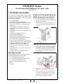
1 GENERAL INFORMATION
Description
The following conventions are used throughout this
manual to simplify navigation and device
operation:
• Safety Instructions need to be observed in
order to protect the operators and equipment;
there are identified with Bold text and the
This section provides a general overview of the
iVIZION® Series Next-Generation Banknote
Acceptor pictured in Figure 1-1. This section is
designed to help the user navigate through this
guide with ease. It includes the following information:
•
•
•
•
•
•
•
•
iVIZION® Units
Product Descriptions
User Cautions
Primary Features
Component Names
Specifications
Unit Dimensions
following pictographs:
• Special Notes affect the use of the Banknote
Acceptor; these are identified with italic text
and the following pictograph:
• Steps requiring the operator to perform specific
actions; these are identified with sequential numbers
(1., 2., 3., etc).
Technical Contact Information
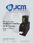
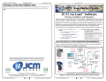
iVIZION Units
LD Specification
SS Specification
SH Specification
Figure 1-1 iVIZION Unit
P/N 960-100929R_Rev. 5 {EDP #148849}
1-1
© 2014, JAPAN CASH MACHINE CO., LTD.
Section 1
iVIZION® Series Next-Generation Banknote Acceptor Unit
General Information
Model Descriptions
Software Descriptions
Table 1-1 lists the product model number
descriptions.
Table 1-3 lists the product software number
descriptions.
Table 1-1 iVIZION Model Number Specifications
No
(1)
(2)
Table 1-3 iVIZION Software Number Specifications
Model: iVIZION - * * * - * *
No
(1)(2)(3)
No
(4)
(A)
(B)
(C)
(D)
Validation Head
1: Standard
2 - 9: Reserved
CPU Board (Memory)
0: Standard
1 - 9: Reserved
Transport Unit Type
(3)
0: Standard
1: SH Specification
2 - 9: Reserved
(4)
SS: Security Stacker Down
SH: Stacker Horizontal
LD: Less Down (No Stacker)
No
(A)
(B) (C)
(D)
(E)
Software Model Name
Denomination (Country Code)
Interface Protocol Name
Software Version
Precautions
Stacker Type
Type 1
Type Descriptions
1. (Type 1) Do not insert a torn, folded, or wet
Banknote; it may cause a jam inside the unit.
2. (Type 2) Do not expose the unit to water. The unit
contains several precision electronic devices that
can be damaged if water or any liquid is sprayed
or spilled into the unit.
3. (Type 3) Do not install the unit in a dusty
environment. Dust may affect/degrade the
sensor’s performance.
Type: * * * - 00 - * * * * *
No
Box Capacity
(a)(b)(c) (d)
Type 3
The Figure 1-2 symbols are defined as follows:
Table 1-2 iVIZION Type Number Specifications
No
Type 2
Figure 1-2 Precautionary Symbols
Table 1-2 lists the product type number
descriptions.
(a)
Software: iVIZION-* * *-* * * * * - * * * - V *.* *
(e)(f)(g)(h)(i)
*
5: 500 notes (New Banknote)
9: 900 notes (New Banknote)
U: 3000 notes (Street Grade Banknote)
0: No Cash Box
(b) Box Type
User Cautions
(c) Box Handle
Careful measures were taken in the design of this
product to ensure its quality; however, the following cautions pertain to all users and should be
followed for safe operation.
0: Standard
0: Standard
(d) Transport Unit Type
00: Standard
(e)
(f)
Bezel (Option)
Installation Cautions
0: Without Bezel
1: With LED Bezel (UBA Standard 85)
The Installation Cautions are defined as follows:
ICB (RFID Type)
1. Do not allow the unit to endure or operate at a
high temperature, in high humidity and/or dusty
environment.
2. Do not install the unit in an area with excessive
vibration or shock present.
3. Unit is not designed for outside installation. Be
sure that the host machine contains enough protection to avoid wet or dusty conditions when
installing in either an indoor or open-air space.
4. Avoid exposing the unit to direct sunlight/incandescent lamp illumination with a gradient angle
of 15 degrees or more, and illumination index of
3,000 Lux or less.
5. Ensure that the host machine is designed for daily
operational access for maintenance and/or clearing a Banknote Jam.
0: None
1: ICB-Compliant (Standard) (for SS/SH Version Only)
Optional Board (Memory)
(g)
(h)
0: Standard Memory (64M Bit)
1: Memory Extension Board (128M bit)
2: Memory Extension Board (192M bit)
Input/Output Signal Selection
P: Photo-Coupler Isolation (Standard)
R: RS232C
External Harness Type
(d)
0: No Harness
1: Standard Harness (One side cut)
2: Harness (with USB I/F Cable) (One side cut)
3: Harness 2 (with Connector and USB I/F Cable)
4: SS/SH Harness (with USB I/F Cable) (One side cut)
5: SS/SH Harness 2 (with Connector and USB I/F Cable)
6: Harness (with USB I/F Cable and JPL Connector)
(1m one side cut)
*. The number of stacked Notes depends on the Banknote’s condition.
P/N 960-100929R_Rev. 5 {EDP #148849}
1-2
© 2014, JAPAN CASH MACHINE CO., LTD.
General Information
iVIZION® Series Next-Generation Banknote Acceptor Unit
Mounting, Dismounting & Transportation
Section 1
WARNING: This Unit is designed
for use with a Current limiting
Power Source! Design the Host
Cabinet space to meet all local
related safety standards.
1. Be sure to turn the Power OFF before mounting
or removing the Unit from its permanent location.
Plugging or unplugging Connector Plugs from
their receptacles while the Power is ON may
cause damage to the Unit.
2. When reassembling a disassembled Unit Part,
ensure that the each part is properly replaced in its
correct original location.
3. Be sure to carry the Unit by both hands when
transporting it. Holding the Unit by one hand may
cause personal injury if the Unit accidently
becomes disassembled and drops away.
4. Be careful not to use excessive outside pressure
on the Unit, or subject it to excessive vibration
during transportation.
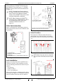
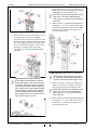
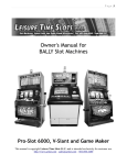
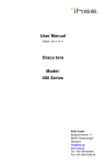
Banknote Fitness Requirements
The following Banknote types may not validate
correctly, or can cause a Banknote jam and/or damage to the Unit’s Transport path. Banknotes exhibiting the conditions listed below and illustrated in
Figure 1-3 should be avoided:
• Torn
• Having excessive folds
• Dirty
• Wet
• Having excessive wrinkle
• Adhering foreign objects and/or oil
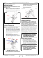
Preventive Maintenance
1. Be sure to turn the Power OFF on the Unit before
beginning a maintenance procedure. The equipment can produce abnormal operating signals
while in maintenance mode that may cause personal injury.
2. If the Validator Section is dirty due to dust, foreign objects or other such debris adhering to it,
Banknote acceptance rates will degrade. Clean
the Unit once a month to keep its performance
stable.
3. Use a soft, lint-free cloth, cotton swab or a compressed air spray to clean dust and debris from the
Banknote path.
Damaged Banknotes
Wrinkled Banknotes
Caution: DO NOT use any alcohol,
solvents, scouring agents or citrus
based cleaners that can damage
the plastic surfaces of the device
when cleaning it.
Curled Banknotes
4. Do not disassemble the Unit incorrectly or redesign it in any way. Unauthorized use by inadequately trained personnel, or use outside the
original manufacturer’s intent for operation voids
the warranty.
5. When the Unit is exposed to liquid such as water,
wipe with a micro fiber cloth to dry the wet areas
immediately. Remaining liquids may affect and
degrade the Sensors and the Validation
Section’s performance.
Folded or Partial Banknotes
Figure 1-3 Unacceptable Banknotes
Caution: Make Interface Harness
connections to the Host Machine
shorter than 9.84 Feet (3 Meters) in
length. Cut off all unused portions
of the Interface Harness wiring to
avoid static electrical effects or
short circuit possibilities that
could cause damage to the Unit.
P/N 960-100929R_Rev. 5 {EDP #148849}
1-3
© 2014, JAPAN CASH MACHINE CO., LTD.
Section 1
iVIZION® Series Next-Generation Banknote Acceptor Unit
General Information
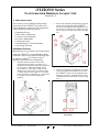
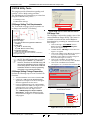
Reference Paper Use Precautions
When calibration, using the KS-072/KS-089 Reference Paper, is complete, protect the Reference
Paper by handling as follows:
• Ensure that the Reference Paper Carrier is kept
in an upright position following use
(See Figure 1-4 a) or, replace it into its
protective Shipping Carton when calibration is
complete (See Figure 1-4 b).
KS-072/KS-089
Reference
Paper
a
KS-072/KS-089
Reference Paper
Shipping Carton
b
Figure 1-4 Reference Paper Handling Precautions
• Do not lay the Reference Paper Carrier down
on any irregular surface, otherwise the
Reference Paper may become wrinkled making
it useless for future calibration use.
• ALWAYS return each Reference Paper into its
protective Shipping Carton following each use.
Primary Features
The iVIZION® Series of Banknote Acceptor
contains the following primary features:
• Easily swappable single Validation Head for
inventory and maintenance efficiency.
• CIS technology allowing 100% scanning of
document details and fine line imagery.
• RFID Intelligent Cash Box with lockable
Frame Unit, and designed for one-hand
removal without the need to use a Button or
Lever to release the Cash Box.
P/N 960-100929R_Rev. 5 {EDP #148849}
1-4
© 2014, JAPAN CASH MACHINE CO., LTD.
General Information
iVIZION® Series Next-Generation Banknote Acceptor Unit
Section 1
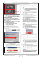
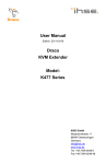
Component Names
Figure 1-5 illustrates the iVIZON® component names and locations.
H
U
I
O
J
K
LD Frame
A
V
N
M
L
D
E
B
F
W
C
R
S
Q
G
HC Cash Box
and Frame
A.
B.
C.
D.
E.
F.
G.
H.
I.
J.
K.
L.
M.
P
T
N. Power ON LED (Green)
O. USB (Mini-B) Software Download/Calibration
& Maintenance Connector
P. Cash Box
Q. Stack Volume Indicator Window
R. Cash Box Window - confirms the last stacked
Banknote Denomination Value
S. Lock Installation Hole (user provided)
T. Pusher Lever - manually moves the Pusher
Plate down (Activate lever to confirm the denom-
Acceptor Unit
Front Upper Guide Access Lever (Acceptor Unit)
Bezel (Option)
Interface Connector
Rear Upper Guide Access Lever (Transport Unit)
Transport Unit
Frame Housing (SS Specification)
DIP Switch Block (Denomination INHIBIT)
DIP Switch Block (JCM Custom Private Line)
Acceptor Unit Release Pushbutton
Status LED (4 Colors: Red/Yellow/Green & Blue)
Front Panel Bezel JPL Connector
Transport Unit Release Lever
ination value through Cash Box Windows “R”)
U. Frame Housing (LD Specification)
V. Frame Housing (SH Specification)
W. HC Cash Box Assembly
Figure 1-5 iVIZION Component Names
P/N 960-100929R_Rev. 5 {EDP #148849}
1-5
© 2014, JAPAN CASH MACHINE CO., LTD.
Section 1
iVIZION® Series Next-Generation Banknote Acceptor Unit
General Information
Specifications (iVIZION SS/SH Specifications)
Technical Specifications
Table 1-4 iVIZION SS/SH Technical Specifications
98% or greater
Acceptance Rate*:
Banknote Types Accepted:
The following Banknote types are excluded:
a) Banknotes with unclear graphics
b) Double (dual) notes
c) Worn, dirty, wet, stained, torn or excessively wrinkled Banknotes
d) Banknotes having folded corners or edges
e) Banknotes having the wrong cut dimensions or a printing displacement
f) Returned Banknotes because of incorrect or failed insertion.
Long edge: SS: 110-170 mm (4.33-6.69 in.)
SH: 110-177 mm (4.33-6.96 in.)
Short edge: 60-85 mm (2.36-3.35 in.).
Standard Specification
a)
b)
c)
d)
e)
Read Code interleaved: 2 of 5
Narrow Bar: 0.5mm-0.6mm (0.019-0.023 in.)
Wide Bar: Narrow Bar = 3:1
Characters: 18 Characters
Print Position: Middle (by dividing a Coupon equally on the left, right, top and
bottom of the Coupon’s exact center)
f) Print Width: Wider than 10mm (0.39 in.).
Barcode Coupon†:
Insertion Direction:
Processing Speed:
Validation Method:
Diagnostic Indicators:
Escrow:
Cash Box Type‡:
Cash Box Capacity**:
Fraud Detection:
Interface††:
Refer to the specific Country’s Software Information Sheet.
Approximately 2 seconds from Banknote insertion to Vend signal output.
Approximately 3 seconds from Banknote insertion to completion of the
stacking operation.
Optical
Power LED, Status LED, Bezel LED (Optional)
1 Note
Secure Cash Box
Intelligent Cash Box (available with RFID Specification)
SS: Standard 500 Banknotes / Large 900 Banknotes
SH: HC Cash Box: 3000 Banknotes
Equipped
USB Interface: USB Specification Rev.2.0
Serial Interface: Photo-Coupler Isolation
Serial Interface: RS232C Communication Protocol.
*. Refer to the specific Country’s “Software Information Sheet” for each Country’s particular Banknote acceptance rate.
†. Refer to the specific Country’s “Bar Code Coupon Specification” for more details.
‡. User supplied installed Locks (including the attached Plate, Lock and Key).
**.The number of Notes stacked depends on the Banknote’s condition.
††.The Interface Harness connecting to the Host should be less than 3m.
P/N 960-100929R_Rev. 5 {EDP #148849}
1-6
© 2014, JAPAN CASH MACHINE CO., LTD.
General Information
iVIZION® Series Next-Generation Banknote Acceptor Unit
Section 1
Environmental Specifications
Table 1-5 iVIZION SS/SH Environmental Specifications
Operating Temperature:
Storage Temperature:
Relative Operating Humidity:
Relative Storage Humidity:
Installation:
5º C to +50º C (41º F to 122º F)
-20º C to +70º C (-4º F to 158º F)
15% to 85% RH (non-condensed)
15% to 85% RH (non-condensed)
Indoors Only
Hydrothermal Condition Table
35°C/85%
[RH%]
50°C/40%
Allowable Operating
Temperature and
Humidity Range
[°C]
Electrical Specifications
Table 1-6 iVIZION SS/SH Electrical Specifications
12V DC (-5%) to 24V DC (+10%) [NOTE: Use a Current Source Limiting
Power Supply]
Standby: 24V DC = 0.2A, 12V DC = 0.2A
Operation: 24V DC = 1.3A, 12V DC = 2.3A
Maximum: 24V DC = 3.2A, 12V DC = 3.0A
Supply Voltage:
Current Consumption:
Structural Specifications
Table 1-7 iVIZION SS Structural Specifications
Weight Empty:
Mounting:
Outside Dimensions:
SS: Approximately 4.1kg (9.04 lbs)
SH: Approximately 7.6kg (16.75 lbs) (with HC Cash Box)
Horizontal (Maximum gradient limitation within 50 degrees;
See Figure 1-9 on page 1-12)
Refer to “iVIZION Banknote Acceptor SS Unit Outside Dimensions” on
page 1-10 and “iVIZION Banknote Acceptor SH Unit Outside Dimensions”
on page 1-11 of this document.
P/N 960-100929R_Rev. 5 {EDP #148849}
1-7
© 2014, JAPAN CASH MACHINE CO., LTD.
Section 1
iVIZION® Series Next-Generation Banknote Acceptor Unit
General Information
Specifications (iVIZION LD Specifications)
Technical Specifications
Table 1-8 iVIZION LD Technical Specifications
98% or greater
Acceptance Rate*:
Banknote Types Accepted:
The following Banknote types are excluded:
a) Banknotes with unclear graphics
b) Double (dual) notes
c) Worn, dirty, wet, stained, torn or excessively wrinkled Banknotes
d) Banknotes having folded corners or edges
e) Banknotes having the wrong cut dimensions or a printing displacement
f) Returned Banknotes because of incorrect or failed insertion.
Long edge: 110-170 mm (4.33-6.69 in.)
Short edge: 60-85 mm (2.36-3.35 in.).
Standard Specification
a)
b)
c)
d)
e)
Read Code interleaved: 2 of 5
Narrow Bar: 0.5mm-0.6mm (0.019-0.023 in.)
Wide Bar: Narrow Bar = 3:1
Characters: 18 Characters
Print Position: Middle (by dividing a Coupon equally on the left, right, top and
bottom of the Coupon’s exact center)
f) Print Width: Wider than 10mm (0.39 in.).
Barcode Coupon†:
Insertion Direction:
Processing Speed:
Validation Method:
Diagnostic Indicators:
Escrow:
Fraud Detection:
Interface‡:
Refer to the specific Country’s Software Information Sheet.
Approximately 2 seconds from Banknote insertion to Vend signal output.
Optical
Power LED, Status LED, Bezel LED (Optional)
1 Note
Equipped
USB Interface: USB Specification Rev.2.0
Serial Interface: Photo-Coupler Isolation
Serial Interface: RS232C Communication Protocol.
*. Refer to the specific Country’s “Software Information Sheet” for each Country’s particular Banknote acceptance rate.
†. Refer to the specific Country’s “Bar Code Coupon Specification” for more details.
‡. The Interface Harness connecting to the Host should be less than 3m.
P/N 960-100929R_Rev. 5 {EDP #148849}
1-8
© 2014, JAPAN CASH MACHINE CO., LTD.
General Information
iVIZION® Series Next-Generation Banknote Acceptor Unit
Section 1
Environmental Specifications
Table 1-9 iVIZION LD Environmental Specifications
Operating Temperature:
Storage Temperature:
Relative Operating Humidity:
Relative Storage Humidity:
Installation:
5º C to +50º C (41º F to 122º F)
-20º C to +70º C (-4º F to 158º F)
15% to 85% RH (non-condensed)
15% to 85% RH (non-condensed)
Indoors Only
Hydrothermal Condition Table
35°C/85%
[RH%]
50°C/40%
Allowable Operating
Temperature and
Humidity Range
[°C]
Electrical Specifications
Table 1-10 iVIZION LD Electrical Specifications
12V DC (-5%) to 24V DC (+10%) [NOTE: Use a Current Source Limiting
Power Supply]
Standby: 24V DC = 0.2A, 12V DC = 0.2A
Operation: 24V DC = 1.3A, 12V DC = 2.3A
Maximum: 24V DC = 3.2A, 12V DC = 3.0A
Supply Voltage:
Current Consumption:
Structural Specifications
Table 1-11 iVIZION LD Structural Specifications
Weight Empty:
Mounting:
Outside Dimensions:
Approximately 2.3kg (5.07 lbs)
Horizontal (Maximum gradient limitation within 50 degrees;
See Figure 1-9 on page 1-12)
Refer to “iVIZION LD Unit Outside Dimensions” on page 1-14 of this document.
P/N 960-100929R_Rev. 5 {EDP #148849}
1-9
© 2014, JAPAN CASH MACHINE CO., LTD.
Section 1
iVIZION® Series Next-Generation Banknote Acceptor Unit
General Information
iVIZION SS Entire Unit Outside Dimensions
Figure 1-6 illustrates the iVIZION SS entire Unit outside dimensions.
NOTE: All Dimensions are in Millimeters
Figure 1-6 iVIZION Banknote Acceptor SS Unit Outside Dimensions
P/N 960-100929R_Rev. 5 {EDP #148849}
1-10
© 2014, JAPAN CASH MACHINE CO., LTD.
General Information
iVIZION® Series Next-Generation Banknote Acceptor Unit
Section 1
iVIZION SH Entire Unit Outside Dimensions
Figure 1-7 illustrates the iVIZION SH entire Unit outside dimensions.
NOTE: All Dimensions are in Millimeters
Figure 1-7 iVIZION Banknote Acceptor SH Unit Outside Dimensions
P/N 960-100929R_Rev. 5 {EDP #148849}
1- 11
© 2014, JAPAN CASH MACHINE CO., LTD.
Section 1
iVIZION® Series Next-Generation Banknote Acceptor Unit
General Information
iVIZION SS/SH Installation/Maintenance Space Requirements
Figure 1-8 illustrates the iVIZION® SS installation and maintenance space requirements.
NOTE: All Dimensions are in Millimeters
Figure 1-8 iVIZION SS Unit Installation and Maintenance Space Requirements Diagram
NOTE: If a maintenance space clearance
area is unavailable, the iVIZION® SS Unit
will need to be dismounted when
maintenance procedures are to be
performed.
Caution: When installing the iVIZION SS
Unit into a Host Machine, do not mount
it tilted downward more than 50 degrees
from a Horizontal position
(See Figure 1-9).
Maximum Angle
Figure 1-9 Maximum Gradient Angle = 50 Degrees
P/N 960-100929R_Rev. 5 {EDP #148849}
1-12
© 2014, JAPAN CASH MACHINE CO., LTD.
General Information
iVIZION® Series Next-Generation Banknote Acceptor Unit
Section 1
Figure 1-10 illustrates the iVIZION® SH installation and maintenance space requirements.
134.2
NOTE: All Dimensions are in Millimeters
57.3
505.5
610.9
599.1
637.1
696.2
58
.8º
85.5º
234.2
72.2
Figure 1-10 iVIZION SH Unit Installation and Maintenance Space Requirements Diagram
NOTE: The Cash Box is hanging on the
Unit. Be careful that the Cash Box does
NOT touch the Host Machine and be sure
that there is enough space under the Cash
Box to be seated/removed properly.
Caution: When installing the iVIZION SH
Unit into a Host Machine, do not mount
it tilted downward more than ±5 degrees
from a Horizontal position.
P/N 960-100929R_Rev. 5 {EDP #148849}
1-13
© 2014, JAPAN CASH MACHINE CO., LTD.
Section 1
iVIZION® Series Next-Generation Banknote Acceptor Unit
General Information
iVIZION LD Specification Unit Dimensions
Figure 1-11 illustrates the iVIZION® LD Unit Outside Dimensions.
NOTE: All Dimensions are in Millimeters
Figure 1-11 iVIZION LD Unit Outside Dimensions
Figure 1-12 illustrates the iVIZION® LD Unit with Bezel Outside Dimensions.
NOTE: All Dimensions are in Millimeters
Figure 1-12 iVIZION LD Unit with Bezel Outside Dimensions
P/N 960-100929R_Rev. 5 {EDP #148849}
1-14
© 2014, JAPAN CASH MACHINE CO., LTD.
General Information
iVIZION® Series Next-Generation Banknote Acceptor Unit
Section 1
Various Cash Box Unit Dimensions
Standard Cash Box Outside Dimensions
Figure 1-13 illustrates the iVIZION® Standard Cash Box Outside Dimensions.
NOTE: All Dimensions are in Millimeters
Figure 1-13 iVIZION Standard Cash Box Outside Dimensions
Large Cash Box Outside Dimensions
Figure 1-14 illustrates the iVIZION® Large Cash Box Outside Dimensions.
NOTE: All Dimensions are in Millimeters
Figure 1-14 iVIZION Large Cash Box Outside Dimensions
P/N 960-100929R_Rev. 5 {EDP #148849}
1-15
© 2014, JAPAN CASH MACHINE CO., LTD.
Section 1
iVIZION® Series Next-Generation Banknote Acceptor Unit
General Information
HC Cash Box Outside Dimensions
Figure 1-15 illustrates the iVIZION® HC Cash Box Outside Dimensions.
NOTE: All Dimensions are in Millimeters
Figure 1-15 iVIZION HC Cash Box Outside Dimensions
P/N 960-100929R_Rev. 5 {EDP #148849}
1-16
© 2014, JAPAN CASH MACHINE CO., LTD.
General Information
iVIZION® Series Next-Generation Banknote Acceptor Unit
Section 1
Technical Contact Information
Americas
Asia and Oceania
JCM AMERICAN
Phone: +1-702-651-0000
JCM GOLD (HK) LTD.
Phone: +852-2429-7187
Fax: +852-2929-7003
Fax: +1-702-644-5512
Unit 1-7, 3/F., Favor Industrial Centre
925 Pilot Road, Las Vegas, NV 89119
2-6 Kin Hong Street, Kwai Chung,
E-mail: [email protected]
N.T. Hong Kong
Europe, Africa, Russia & Middle East
JCM EUROPE GMBH
Phone: +49-211-530-645-60
Fax: +49-211-530-645-65
E-mail: [email protected]
JAPAN CASH MACHINE CO., LTD. (HQ)
Phone: +81-6-6703-8400
Fax: +81-6-6707-0348
Muendelheimer Weg 60
2-3-15, Nishiwaki, Hirano-ku, Osaka 547-0035
JAPAN
D-40472 Duesseldorf Germany
E-mail: [email protected]
E-mail: [email protected]
UK & Ireland
JCM EUROPE (UK OFFICE)
Phone: +44 (0) 190-837-7331
All of these Websites are available via:
http://www.jcmglobal.com
Fax: +44 (0) 190-837-7834
Unit B, Third Avenue
Denbigh West Business Park
Bletchley, Milton Keynes,
Buckinghamshire MK1 1DH, UK
E-mail: [email protected]
P/N 960-100929R_Rev. 5 {EDP #148849}
1-17
© 2014, JAPAN CASH MACHINE CO., LTD.
Section 1
iVIZION® Series Next-Generation Banknote Acceptor Unit
General Information
THIS PAGE INTENTIONALLY LEFT BLANK
P/N 960-100929R_Rev. 5 {EDP #148849}
1-18
© 2014, JAPAN CASH MACHINE CO., LTD.
iVIZION® Series
Next-Generation Banknote Acceptor Unit
Section 2
2 INSTALLATION
This section provides installation and operating
instructions for the iVIZION® Series Next-Generation Banknote Acceptor Unit. The information
within contains the following features:
• Installation Process
• DIP Switch Configurations
• Connector Pin Assignments
• Preventive Maintenance
• Cleaning Procedure
• Standard Interface Circuit Schematics
• Operational Flowchart
2. When a side mounting configuration is preferred,
bolt the left and right side of the iVIZION®
Frame into its intended related Machine’s location using six (6) M4 Screws on both sides of the
Frame (3 Screws on each side as shown in Figure
2-2).
Installation Process
Mounting holes are provided in each Frame Unit to
attach the iVIZION® to a related Machine during
installation. Select and perform the following steps
to install the iVIZION® Unit in the related
Machine’s particular Frame configuration:
1. Install the Interface Harness to the Frame
Grounding Plate (FG PLT) (See Figure 2-1 a)
using the two (2) Floating Collars (See Figure 2-1
b), the single (1) M2.6x12 W Washer Screw
(See Figure 2-1 c), the single (1) M2.6x10 W
Washer Screw (See Figure 2-1 d) and the single
(1) M2.6 Nylon Nut (See Figure 2-1 e) onto the
Frame Assembly. See the Figure 2-1 circled inset
to visually see the assembly completed as
required.
a
c
d
Figure 2-2 M4 Screws Locations (Left/Right Side)
3. When an end mounting configuration is preferred,
remove the Cash Box and attach the rear end of
the iVIZION® Frame into its intended location
using four (4) UNC6-32 Flat Head Screws from
inside the back end of the Frame as shown in Figure 2-3.
e
b
b
Figure 2-3 Flat Head Screws Locations
(Rear Side)
Figure 2-1 Interface Harness Installation Location
P/N 960-100929R_Rev. 5 {EDP #148849}
2-1
© 2014, JAPAN CASH MACHINE CO., LTD.
Section 2
iVIZION® Series Next-Generation Banknote Acceptor Unit
When installing the iVIZION® SH Unit into the
Host Machine, refer to the Figure 1-7 “iVIZION
Banknote Acceptor SH Unit Outside Dimensions”
on page 1-11.
Installation
1-1/8
2x16.2 +0.1
0
NOTE: The length from Frame surface to
the edge of the M4 Screws should be within
4mm in order not to puncture the Plastic
Surface of the iVIZION® Frame when a side
mounting configuration is preferred.
NOTE: When installing the iVIZION® LD
Version Unit into a related Machine, refer to
the iVIZION Optional LD Version Unit
Installation detailed information on
page 2-11.
1
0.
+ 0
1
9.
1
φ
in. (2
8.6m
m)
20.5m
m
2x
Use a Key Spacer if backlash
affects lock/unlock function.
5/8 in
. (15.9
mm)
Cable Interconnection
Figure 2-4 illustrates the Cable Harness interconnection requirements between the iVIZION® and a
Host Machine.
b
* The length of each lock indicated followed standard size.
Millimeters in brackets for inches are only reference.
Figure 2-5 Lock Size
Unlock Procedure
c
Each Lock has a different rotation direction to
unlock. Make sure when the lock(s) are installed
the rotation is in the correct direction(s) (See Figure
2-6).
5/8 in. or 1-1/8 in. Lock
a
20.5mm Lock
d
a)
b)
c)
d)
iVIZION® Unit
Interface Connector (iVIZION)
Harness
Host Machine (e.g., Game Machine, Kiosk, etc.)
Figure 2-6 Unlock Rotation Direction
NOTE: When using only one lock, install the
Key Cap in the unused key hole (See Figure
2-7).
Figure 2-4 Cable Interconnection
Lock Installation
Use Key Cap
One or two security locks can be installed onto a
iVIZION® Cash Box. When installing a security
lock, the following attachment accessories may be
required:
• Key Spacers
• Plate Lock Keys
• Key Cap Attachment
Choose a Lock that fits a standard size hole dimension format (See Figure 2-5). In addition, when two
locks are installed, both locks must be identical.
P/N 960-100929R_Rev. 5 {EDP #148849}
Figure 2-7 Key Cap Installation
2-2
© 2014, JAPAN CASH MACHINE CO., LTD.
Installation
iVIZION® Series Next-Generation Banknote Acceptor Unit
DIP Switch Configurations
NOTE: When changing the type of iVIZION
Serial Communications, Switches JP2 and
JP3 located on the Controller CPU Board
must be set to identical switch positions.
This portion provides the denomination DIP Switch
Block Settings for the iVIZION® Unit.
Table 2-1 Denomination INHIBIT DIP Switch
Settings
Primary LED Indications
Validation CPU Board SW1
The iVIZION® Unit’s two LEDs illuminate different colors when various operating and error conditions occur.
SW1
Switch
No.
1
2
3
4
5
6
7
8
Switch ON
Switch OFF
VEND 1 INHIBIT
VEND 2 INHIBIT
VEND 3 INHIBIT
VEND 4 INHIBIT
VEND 5 INHIBIT
VEND 6 INHIBIT
VEND 7 INHIBIT
VEND 1 ACCEPT
VEND 2 ACCEPT
VEND 3 ACCEPT
VEND 4 ACCEPT
VEND 5 ACCEPT
VEND 6 ACCEPT
VEND 7 ACCEPT
OFF (Fixed)
Section 2
Table 2-5 LED Error Pattern Indications
No.
Condition
1
OFF
LED Indications
Power LED*
Status LED
2
Initializing
Extinguished
(OUT)
Lit Green
3
Stand-by
Lit Green
4
5
Lit Green
Lit Green
6
Reject
Banknote Jam
Abnormal
Error
Extinguished
(OUT)
Blue Flashes
Extinguished
(OUT)
Green Flashes
Yellow Flashes
Lit Green
Red Flashes
Table 2-2 JCM Private Line DIP Switch Setting
7
Downloading
Lit Green
Lit Red
Lit Green
Validation CPU Board JP1
8
Performance Test
(Stand-by)
Lit Green
Lit Blue
N/A*
*. Not Applicable (N/A). Used to enter “Test Mode”.
↔
O
JP1
C
Switch
No.
*. The Power LED lights Green when Power is supplied to the Unit.
Mark
Non-Marked (O)
Marked (C)
RS-485 Resistance RS-485 Resistance UnTerminated
Terminated
1
Table 2-3 Software DIP Switch Settings
Controller CPU Board SW1
SW1
Switch
No.
Switch ON
Switch OFF
1
2
3
4
N/A*
N/A*
N/A*
N/A*
OFF (Fixed)
OFF (Fixed)
OFF (Fixed)
OFF (Fixed)
*. Not Applicable (N/A). Never Switched to ON.
Table 2-4 Serial Communications DIP Switch
Settings
Controller CPU Board JP2 & JP3
Mark
JP2
JP3
R↔P
R↔P
Switch No.
Non-Marked (R)
JP2
RS232C
JP3
RS232C
Marked (P)
Photo-Coupler
Isolation (Standard)
Photo-Coupler
Isolation (Standard)
P/N 960-100929R_Rev. 5 {EDP #148849}
2-3
© 2014, JAPAN CASH MACHINE CO., LTD.
Section 2
iVIZION® Series Next-Generation Banknote Acceptor Unit
Installation
Connector Pin Assignments
Table 2-6 lists the iVIZION SS/LD Interface Connector Pin Assignments.
Table 2-6 iVIZION SS/LD USB Connection Pin Assignments
Back Side View
Socket Housing (Transport Unit Side): DR1B026JA1 (JCM)
Pin Housing (Frame Side): DR1R026PA1 (JCM)
Contact Type (Frame Side): D02-22-26P-10000 (JAE) (Poles except 1, 9, 18 & 26)
Recommended Wire: UL1061 AWG#26
Contact Type (Frame Side): D02-22-22P-10000 (JAE) (Pole# 1, 9, 18 & 26)
Pin No.
Signal Name
I/O* †
1
2
3
4
5
6
7
8
9
10
11
12
13
14
15
16
17
18
19
20
21
22
23
24
25
26
24V DC (POWER)
M-RESET
USBUSB+
USB GND
TTL-TXD
TTL-RXD
LED POWER
24V DC (POWER)
RS232 GND
TXD
I/F +12V DC
Vbus
JP+
TTL-G
LEDccTalk (P)
POWER GND
I/F GND
RXD
DET-GND
DET
JPSU SELECT
ccTalk (S)
POWER GND
POWER
IN
IN/OUT
IN/OUT
SG
OUT
IN
OUT
POWER
SG
OUT
IN
IN
IN/OUT
SG
IN
IN/OUT
POWER
SG
IN
IN
OUT
IN/OUT
IN
IN/OUT
POWER
Function
+24V DC Power
Banknote Acceptor Master Reset Input Signal Line
USB Communication Input/Output Signal Line
USB Communication Input/Output Signal Line
USB Communication Ground (0V DC)
LED Drive Line (anode)
+24V DC Power
Interface Power Supply (+12VDC)
USB Communication Vbus Signal Line (+5V DC)
LED Drive Line (cathode)
Power Ground (0V DC)
Connect to DET (Pin-22)
Connect to DET GND (Pin-21)
SS/SU Selection‡
Power Ground (0V DC)
*. I/O (Input/Output) Terminal as viewed from outside the Banknote Acceptor.
†. SG = Signal Ground.
‡. No Connection = SS Version, Connect to any unused SG (Pin #10, Pin #15 or Pin #19) = SU Version.
P/N 960-100929R_Rev. 5 {EDP #148849}
2-4
© 2014, JAPAN CASH MACHINE CO., LTD.
Installation
iVIZION® Series Next-Generation Banknote Acceptor Unit
Section 2
Connector Pin Assignments (Continued 1)
Table 2-7 lists the iVIZION SS/LD Photo-Coupler Connector Pin Assignments.
Table 2-7 iVIZION SS/LD Photo-Coupler Connector Pin Assignments
Back Side View
Socket Housing (Transport Unit Side): DR1B026JA1 (JCM)
Pin Housing (Frame Side): DR1R026PA1 (JCM)
Contact Type (Frame Side): D02-22-26P-10000 (JAE) (Poles except 1, 9, 18 & 26)
Recommended Wire: UL1061 AWG#26
Contact Type (Frame Side): D02-22-22P-10000 (JAE) (Pole# 1, 9, 18 & 26)
Pin No.
Signal Name
I/O* †
1
2
3
4
5
6
7
8
9
10
11
12
13
14
15
16
17
18
19
20
21
22
23
24
25
26
24V DC (POWER)
M-RESET
USBUSB+
USB GND
TTL-TXD
TTL-RXD
LED POWER
24V DC (POWER)
RS232 GND
TXD
I/F +12V DC
Vbus
JP+
TTL-G
LEDccTalk (P)
POWER GND
I/F GND
RXD
DET-GND
DET
JPSU SELECT
ccTalk (S)
POWER GND
POWER
IN
IN/OUT
IN/OUT
SG
OUT
IN
OUT
POWER
SG
OUT
IN
IN
IN/OUT
SG
IN
IN/OUT
POWER
SG
IN
IN
OUT
IN/OUT
IN
IN/OUT
POWER
Function
+24V DC Power
Banknote Acceptor Master Reset Input Signal Line
LED Drive Line (anode)
+24V DC Power
Serial Communication Output Signal Line
Interface Power Supply (+12VDC)
LED Drive Line (cathode)
Power Ground (0V DC)
Photo-Coupler Communication GND
Serial Communication Input Signal Line
Connect to DET (Pin-22)
Connect to DET GND (Pin-21)
SS/SU Selection‡
Power Ground (0V DC)
*. I/O (Input/Output) Terminal as viewed from outside the Banknote Acceptor.
†. SG = Signal Ground.
‡. No Connection = SS Version, Connect to any unused SG (Pin #10 or Pin #15) = SU Version.
P/N 960-100929R_Rev. 5 {EDP #148849}
2-5
© 2014, JAPAN CASH MACHINE CO., LTD.
Section 2
iVIZION® Series Next-Generation Banknote Acceptor Unit
Installation
Connector Pin Assignments (Continued 2)
Table 2-8 lists the iVIZION SS/LD RS232C Connector Pin Assignments.
Table 2-8 iVIZION SS/LD RS232C Connector Pin Assignments
Back Side View
Socket Housing (Transport Unit Side): DR1B026JA1 (JCM)
Pin Housing (Frame Side): DR1R026PA1 (JCM)
Contact Type (Frame Side): D02-22-26P-10000 (JAE) (Poles except 1, 9, 18 & 26)
Recommended Wire: UL1061 AWG#26
Contact Type (Frame Side): D02-22-22P-10000 (JAE) (Pole# 1, 9, 18 & 26)
Pin No.
Signal Name
I/O* †
1
2
3
4
5
6
7
8
9
10
11
12
13
14
15
16
17
18
19
20
21
22
23
24
25
26
24V DC (POWER)
M-RESET
USBUSB+
USB GND
TTL-TXD
TTL-RXD
LED POWER
24V DC (POWER)
RS232C GND
TXD
I/F + 12V DC
Vbus
JP+
TTL-G
LEDccTalk (P)
POWER GND
I/F GND
RXD
DET-GND
DET
JPSU SELECT
ccTalk (S)
POWER GND
POWER
IN
IN/OUT
IN/OUT
SG
OUT
IN
OUT
POWER
SG
OUT
IN
IN
IN/OUT
SG
IN
IN/OUT
POWER
SG
IN
IN
OUT
IN/OUT
IN
IN/OUT
POWER
Function
+24V DC Power
Banknote Acceptor Master Reset Input Signal Line
LED Drive Line (anode)
+24V DC Power
RS232C Communication Ground
Serial Communication Output Signal Line
Interface Power Supply (+12V DC)
LED Drive Line (cathode)
Power Ground (0V DC)
Serial Communication Input Signal Line
Connect to DET (Pin-22)
Connect to DET GND (Pin-21)
SS/SU Selection‡
Power Ground (0V DC)
*. I/O (Input/Output) Terminal as viewed from outside the Banknote Acceptor.
†. SG = Signal Ground
‡. No Connection = SS Version, Connect to any unused SG (Pin #15 or Pin #19) = SU Version.
P/N 960-100929R_Rev. 5 {EDP #148849}
2-6
© 2014, JAPAN CASH MACHINE CO., LTD.
Installation
iVIZION® Series Next-Generation Banknote Acceptor Unit
Section 2
Connector Pin Assignments (Continued 3)
Table 2-9 lists the iVIZION SS/LD ccTalk Connector Pin Assignments.
Table 2-9 iVIZION SS/LD ccTalk Connector Pin Assignments
Back Side View
Socket Housing (Transport Unit Side): DR1B026JA1 (JCM)
Pin Housing (Frame Side): DR1R026PA1 (JCM)
Contact Type (Frame Side): D02-22-26P-10000 (JAE) (Poles except 1, 9, 18 & 26)
Recommended Wire: UL1061 AWG#26
Contact Type (Frame Side): D02-22-22P-10000 (JAE) (Pole# 1, 9, 18 & 26)
Pin No.
Signal Name
I/O* †
1
2
3
4
5
6
7
8
9
10
11
12
13
14
15
16
17
18
19
20
21
22
23
24
25
26
24V DC (POWER)
M-RESET
USBUSB+
USB GND
TTL-TXD
TTL-RXD
LED POWER
24V DC (POWER)
RS232C GND
TXD
I/F + 12V DC
Vbus
JP+
TTL-G
LEDccTalk (P)
POWER GND
I/F GND
RXD
DET-GND
DET
JPSU SELECT
ccTalk (S)
POWER GND
POWER
IN
IN/OUT
IN/OUT
SG
OUT
IN
OUT
POWER
SG
OUT
IN
IN
IN/OUT
SG
IN
IN/OUT
POWER
SG
IN
IN
OUT
IN/OUT
IN
IN/OUT
POWER
Function
+24V DC Power
Banknote Acceptor Master Reset Input Signal Line
LED Drive Line (anode)
+24V DC Power
Interface Power Supply (+12VDC)
LED Drive Line (cathode)
ccTalk Communication Power Supply Line
Power Ground (0V DC)
Connect to DET (Pin-22)
Connect to DET GND (Pin-21)
SS/SU Selection‡
ccTalk Communication Signal Line
Power Ground (0V DC)
*. I/O (Input/Output) Terminal as viewed from outside the Banknote Acceptor.
†. SG = Signal Ground.
‡. No Connection = SS Version, Connect to any unused SG (Pin #10, Pin #15 or Pin #19) = SU Version.
P/N 960-100929R_Rev. 5 {EDP #148849}
2-7
© 2014, JAPAN CASH MACHINE CO., LTD.
Section 2
iVIZION® Series Next-Generation Banknote Acceptor Unit
Installation
Connector Pin Assignments (Continued 4)
Table 2-10 lists the iVIZION SS/LD TTL Connector Pin Assignments.
Table 2-10 iVIZION SS/LD TTL Connector Pin Assignments
Back Side View
Socket Housing (Transport Unit Side): DR1B026JA1 (JCM)
Pin Housing (Frame Side): DR1R026PA1 (JCM)
Contact Type (Frame Side): D02-22-26P-10000 (JAE) (Poles except 1, 9, 18 & 26)
Recommended Wire: UL1061 AWG#26
Contact Type (Frame Side): D02-22-22P-10000 (JAE) (Pole# 1, 9, 18 & 26)
Pin No.
Signal Name
I/O* †
1
2
3
4
5
6
7
8
9
10
11
12
13
14
15
16
17
18
19
20
21
22
23
24
25
26
24V DC (POWER)
M-RESET
USBUSB+
USB GND
TTL-TXD
TTL-RXD
LED POWER
24V DC (POWER)
RS232C GND
TXD
I/F + 12V DC
Vbus
JP+
TTL-G
LEDccTalk (P)
POWER GND
I/F GND
RXD
DET-GND
DET
JPSU SELECT
ccTalk (S)
POWER GND
POWER
IN
IN/OUT
IN/OUT
SG
OUT
IN
OUT
POWER
SG
OUT
IN
IN
IN/OUT
SG
IN
IN/OUT
POWER
SG
IN
IN
OUT
IN/OUT
IN
IN/OUT
POWER
Function
+24V DC Power
Banknote Acceptor Master Reset Input Signal Line
TTL Communication Output Signal Line
TTL Communication Input Signal Line
LED Drive Line (anode)
+24V DC Power
Interface Power Supply (+12VDC)
LED Drive Line (cathode)
Power Ground (0V DC)
Connect to DET (Pin-22)
Connect to DET GND (Pin-21)
SS/SU Selection‡
Power Ground (0V DC)
*. I/O (Input/Output) Terminal as viewed from outside the Banknote Acceptor.
†. SG = Signal Ground.
‡. No Connection = SS Version, Connect to any unused SG (Pin #10, Pin #15 or Pin #19) = SU Version.
P/N 960-100929R_Rev. 5 {EDP #148849}
2-8
© 2014, JAPAN CASH MACHINE CO., LTD.
Installation
iVIZION® Series Next-Generation Banknote Acceptor Unit
Section 2
Connector Pin Assignments (Continued 5)
Table 2-11 lists the iVIZION SS/LD Bezel Connector Pin Assignments.
Table 2-11 iVIZION SS/LD Bezel JPL (CN7) Connection Pin Assignments
Front Side View
Polarizing Pin
Connector
CN7
Embossed
ID Pin No.4
Box Pin Header (Control CPU Board Side): A3B-8PA-2DS (71) (HRS) JCM Custom
Socket Housing (Bezel Side): A3B-8D-2C (HRS)
Contact Type (Bezel Side): A3B-2630SCFC (HRS)
Polarizing Pin: A3-GPIN (HRS)*
Recommended Wire: UL1007 AWG#24~30
Pin No.
Signal Name
I/O†
1
2
3
4
5
6
JP+
JP5V DC
VIN
GND
IN/OUT
IN/OUT
OUT
OUT
SG
7
LED POWER
OUT
8
LED 1
IN
Function
Polarizing Pin Key
5V DC Power Supply (Maximum 300mA)
LED Drive Power Supply 12V DC/24V DC (Maximum 300mA)
LED Power Supply 5V (Maximum 20mA Current Limitation
Resistance)
LED Drive Line (cathode) Maximum Sink Current: 300mA
*. Caution: The Embossed Numbers located on the Polarizing Pin Connector, and on the CN7 Connector Numbers indicated in Table 2-11 are different.
The Polarizing Pin Key should be inserted into Pin Position No.4 of the Polarizing Pin Connector.
†. I/O (Input/Output) Terminal as viewed from outside the Banknote Acceptor.
P/N 960-100929R_Rev. 5 {EDP #148849}
2-9
© 2014, JAPAN CASH MACHINE CO., LTD.
Section 2
iVIZION® Series Next-Generation Banknote Acceptor Unit
Preventive Maintenance
Installation
(See Figure 2-10 a). Check at the rear side of the
Frame and remove the jammed Banknote located
there if any (See Figure 2-10 b).
5. A jammed Banknote may also be present on top
of the Cash Box; remove it if present at this
location (See Figure 2-10 c).
Retrieving Banknotes
To retrieve Cash Box deposited Banknotes perform
the following steps:
1. Release the Cash Box from the Frame and pull it
forward.
2. Unlock the Cash Box with a User supplied Key.
3. Open the Cash Box Door and retrieve deposited
Banknotes as illustrated in Figure 2-8.
c
a
Remove
b
Pull Out
Figure 2-10 Retrieving Cash Box Banknote Jam
Cleaning Procedure
Figure 2-8 Retrieving Banknote
Clearing a Banknote Jam
To retrieve a jammed Banknote jammed inside the
Banknote Acceptor Head proceed as follows:
1. Open the Acceptor Unit’s Upper Guide by pressing in on the two (2) Upper Guide Access Buttons
(See Figure 2-9a Blue Arrows) located on each
side of the Upper Guide, and lift the Acceptor top
up and open and remove the jammed Banknote.
2. If the jammed Banknote is not found in the
Acceptor Unit, then
3. Open the Transport Unit’s Upper Guide by pressing in on the Upper Guide Access Lever
(See Figure 2-9b single Blue Arrow) located in
the center of the Upper Guide, and lift the Transport Section up and open and remove the jam.
a
Caution: Do not allow any fluid to remain
on internal components, especially on
the Anti-String Mechanism and in the
Feed-in Sensor’s grooved areas.
Sensor Cleaning Procedure
Remove
Hidden
To clean the lenses, use a lint-free, Micro-Fiber
Cloth and a mild non-abrasive detergent such as
liquid dish soap mixed with water to wipe the dirt
from the Lenses. It is important to keep the
Banknote Path, Rollers, and Belts clean. Use a softlint free, Micro-Fiber Cloth or a Cotton Swab to
wipe dirt and stains from the surfaces of the Optical
Sensors, Rollers and Belts. The Sensor Lenses are
transparent, and made of a polymer material; Handle them with care. When the Unit is exposed to
liquid such as water, wipe and dry the wet areas
immediately. Repeat the cleaning process as needed
until the Transport Path is free of contaminants.
Open
Open
1. Turn the iVIZION® Unit Power OFF.
2. Clean the Sensors and lenses in the Acceptor
Unit, the Transport Unit and on the Cash Box
itself. If necessary, remove each Unit and/or open
their Upper Guides for cleaning. See Figure 2-13
and Table 2-12 to locate all cleaning locations.
b
Remove
Caution: Do not use Alcohol, thinner or
citrus based products for cleaning any
Banknote transport Sensors or surfaces.
The lenses can become clouded by
chemical evaporation residue that may
cause acceptance errors.
a) Acceptor Unit Upper Guide Access Lever
b) Transport Unit Upper Guide Access Lever
Figure 2-9 Open the Upper Guides
4. If the jammed Banknote is not found in the higher
Sections, pull the Cash Box out of the Frame
P/N 960-100929R_Rev. 5 {EDP #148849}
2-10
© 2014, JAPAN CASH MACHINE CO., LTD.
Installation
iVIZION® Series Next-Generation Banknote Acceptor Unit
Section 2
NOTE: When closing the Acceptor or
Transport Unit’s Upper Guides, ensure that
they click firmly into place when being
closed. Also, when reassembling the
iVIZION® Unit, ensure that it re-seats
correctly into place when the reassembly is
complete.
iVIZION Optional LD Version Unit
Installation
Mounting holes are provided in the LD Frame Unit
to attach the iVIZION® LD Unit to a related
Machine during installation. Perform the following
steps to install the iVIZION® LD Version Unit into
the related Machine’s Frame configuration:
1. Install the Interface Harness to the Frame
Grounding Plate (FG PLT) (See Figure 2-11 a)
using the two (2) Floating Collars (See Figure 211 b1 & b2), the related single (1) M2.6x12 W
Washer Screw (See Figure 2-11 c), the single (1)
M2.6x10 W Washer Screw (See Figure 2-11 d)
and the single (1) M2.6 Nylon Nut (See Figure 211 e) onto the upper Frame Assembly Bracket.
See the Figure 2-11 circled inset to visually see
the completed assembly as required.
a
Figure 2-12 M3 Screws Locations
e
b1
c
b2
d
Figure 2-11 Interface Harness Installation Location
2. Bolt the bottom side of the iVIZION® LD Frame
into its intended Machine’s location using four (4)
M3x6 Screws on both bottom sides of the Frame
(2 Screws on each side as shown in Figure 2-12).
P/N 960-100929R_Rev. 5 {EDP #148849}
2- 11
© 2014, JAPAN CASH MACHINE CO., LTD.
Section 2
iVIZION® Series Next-Generation Banknote Acceptor Unit
Installation
iVIZION Sensor Locations
Figure 2-13 illustrates and Table 2-12 lists the iVIZION® various Sensor and Sensor Lens locations.
n
c
e
o
f
g
p
b
k
Hidden
a
h
q
d
m
j
l
Hi
dd
en
Hi
dd
en
i
r
Figure 2-13 iVIZION Sensor Cleaning Locations
Table 2-12 iVIZION Sensor Cleaning Location Types
Sym.
a
b
c
d
e
f
g
h
i
j
k
l
m
n
o
p
q
r
Sensor
Cleaning Method
Entrance Sensors
Exit Sensors
UV Sensor (Upper)
Acceptor Unit
UV Sensor (Lower)
Transmissive Sensor
CIS (Upper)
CIS (Lower)
Feed-in Sensors
Feed-out Sensors
Home Position Sensor
Transport Unit
Home Position Sensor Lens
Nearly Full Sensor
Cash Box Sensor
Home Position Sensor Lens
Cash Box
Cash Box Sensor Lens
Nearly Full Sensor Lens
Anti-Stringing Mechanism
Feed-in Sensor’s Comb Grooves
Wipe area clean using a lint-free cloth such as a Micro-Fiber
Cloth, or blow clean using Compressed Air.*
*. Use only non-flammable compressed air.
P/N 960-100929R_Rev. 5 {EDP #148849}
2-12
© 2014, JAPAN CASH MACHINE CO., LTD.
Installation
iVIZION® Series Next-Generation Banknote Acceptor Unit
Section 2
Standard Interface Circuit Schematics
Figure 2-14 illustrates the iVIZION® USB Circuit Interface Schematic Diagrams.
Controller Side
iVIZION Side
NOTE: The Controller Circuit
Schematic is for reference
only and does not guarantee
the actual Machine’s
functional operation.
Figure 2-14 iVIZION USB Circuit Interface Schematic Diagram
Figure 2-15 illustrates the iVIZION® Photo-Coupler Isolation Circuit Interface Schematic Diagrams.
Controller Side iVIZION Side
NOTE: The Controller Circuit
Schematic is for reference
only and does not guarantee
the actual Machine’s
functional operation.
Figure 2-15 iVIZION Photo-Coupler Circuit Interface Schematic Diagram
P/N 960-100929R_Rev. 5 {EDP #148849}
2-13
© 2014, JAPAN CASH MACHINE CO., LTD.
Section 2
iVIZION® Series Next-Generation Banknote Acceptor Unit
Installation
Interface Circuit Schematics (Continued 1)
Figure 2-16 illustrates the iVIZION® RS232C Circuit Interface Schematic Diagrams.
Controller Side iVIZION Side
NOTE: The Controller Circuit
Schematic is for reference
only and does not guarantee
the actual Machine’s
functional operation.
Figure 2-16 iVIZION RS232C Circuit Interface Schematic Diagram
Figure 2-17 illustrates the iVIZION® ccTalk Circuit Interface Schematic Diagrams.
Controller Side
iVIZION Side
NOTE: The Controller Circuit
Schematic is for reference
only and does not guarantee
the actual Machine’s
functional operation.
Figure 2-17 iVIZION ccTalk Circuit Interface Schematic Diagram
P/N 960-100929R_Rev. 5 {EDP #148849}
2-14
© 2014, JAPAN CASH MACHINE CO., LTD.
Installation
iVIZION® Series Next-Generation Banknote Acceptor Unit
Section 2
Interface Circuit Schematics (Continued 2)
Figure 2-18 illustrates the iVIZION® TTL Circuit Interface Schematic Diagrams.
Controller Side
iVIZION Side
NOTE: The Controller Circuit
Schematic is for reference
only and does not guarantee
the actual Machine’s
functional operation.
Figure 2-18 iVIZION TTL Circuit Interface Schematic Diagram
P/N 960-100929R_Rev. 5 {EDP #148849}
2-15
© 2014, JAPAN CASH MACHINE CO., LTD.
Section 2
iVIZION® Series Next-Generation Banknote Acceptor Unit
Installation
Interface Circuit Schematics (Continued 3)
Figure 2-19 illustrates the iVIZION® LED Circuit Interface Schematic Diagrams.
iVIZION Side
Bezel Side
NOTE: Refer to the Caution
description stated below this
Figure in order to ensure that
each Current Limiting
Resistance Value is correctly
chosen.
Figure 2-19 iVIZION LED Circuit Interface Schematic Diagram
Caution: Select the Current Resistance Limitation Variable depending on the Voltage at the
5th pin connected to the Machine’s input Power Supply.
• Maximum Output Supply
- 4th pin: 5V 300mA
- 5th pin: VIN 300mA
- 7th pin: LED Power 20mA
• Maximum Sink Current
- 8th pin: LED1 300mA
P/N 960-100929R_Rev. 5 {EDP #148849}
2-16
© 2014, JAPAN CASH MACHINE CO., LTD.
Installation
iVIZION® Series Next-Generation Banknote Acceptor Unit
Section 2
Operational Flowchart
Figure 2-20 depicts a typical iVIZION® SS/LD Banknote acceptance flow process (Initialization).
a) Initializing
C) Stand-by return from Figure 2-21
and Figure 2-22.
b) Enter Stand-by Mode
c) Enable Accept?
d) LED Display Extinguished
e) LED Display shows Enable Light
f) Is Banknote inserted?
g) Feed Banknote In
h) Banknote Transporting
i) Banknote Data Sampling
j) Stop Transporting Banknote
A) To Validation Process
(See Figure 2-21 for SS Unit
and Figure 2-22 for LD Unit).
Figure 2-20 iVIZION SS/LD Banknote Acceptor Operational Flowchart (Initializing)
P/N 960-100929R_Rev. 5 {EDP #148849}
2-17
© 2014, JAPAN CASH MACHINE CO., LTD.
Section 2
iVIZION® Series Next-Generation Banknote Acceptor Unit
Installation
Operational Flowchart (Continued 1)
Figure 2-21 depicts a typical iVIZION® SS Banknote flow process (Validation).
A) Begin Validating
a) Is Validation Result OK?
b) Is Banknote Unacceptable?
c) Output the Denomination Value Signal
d) Receive Stacking Command?
e) Reject Banknote
f) Continue Transporting Banknote
g) Is Banknote sent to Stacker?
h) Output a VEND Signal
i) Retry 3 times?
j) Stop Performance: Output Abnormal
Signal (*1)
k) Banknote Stacking
l) Is Stacker Full?
m) Stop Performance: Issue Output Stacker
Full Signal (*2)
C) Return To Stand-by Mode (See Figure 2-20).
*1 When Abnormal Output Signal condition occurs, remove the Banknote causing the malfunction and re-apply power to the Unit, or send a Reset
Command to the Banknote Acceptor.
*2 When a Stacker Full signal occurs, remove the Banknotes from the Cash Box and re-install it into its fully seated position. The iVIZION will the
automatically re-initialize itself.
Figure 2-21 iVIZION SS Banknote Acceptor Operational Flowchart (Part 1 - Validating)
P/N 960-100929R_Rev. 5 {EDP #148849}
2-18
© 2014, JAPAN CASH MACHINE CO., LTD.
Installation
iVIZION® Series Next-Generation Banknote Acceptor Unit
Section 2
Operational Flowchart (Continued 2)
Figure 2-22 depicts a typical iVIZION® LD Banknote flow process (Validation).
A) Begin Validating
a) Is Validation Result OK?
b) Is Banknote Unacceptable?
c) Output the Denomination Value Signal
d) Receive Stacking Command?
f) Continue Transporting Banknote
g) Is Banknote sent to Stacker?
e) Reject Banknote
h) Output a VEND Signal
C) Return To Stand-by Mode (See Figure 2-20)
i) Stop due to Abnormal Condition or return to
Stand-by Mode?
j) Stop Performance: Output Abnormal
Signal (*1)
*1 When Abnormal Output Signal condition occurs, remove the Banknote causing the malfunction and re-apply power to the Unit, or send a Reset
Command to the Banknote Acceptor.
Figure 2-22 iVIZION LD Banknote Acceptor Operational Flowchart (Part 2 - Validating)
P/N 960-100929R_Rev. 5 {EDP #148849}
2-19
© 2014, JAPAN CASH MACHINE CO., LTD.
Section 2
iVIZION® Series Next-Generation Banknote Acceptor Unit
Installation
THIS PAGE INTENTIONALLY LEFT BLANK
P/N 960-100929R_Rev. 5 {EDP #148849}
2-20
© 2014, JAPAN CASH MACHINE CO., LTD.
iVIZION® Series
Next-Generation Banknote Acceptor Unit
Section 3
3 COMMUNICATIONS
This section was intentionally left out due to a Non-Disclosure Agreement requirement.
If this information is required, please contact the closest office location listed below:
Americas
Asia and Oceania
JCM American
JCM Gold (HK) Ltd.
Phone: +1-702-651-0000
Phone: +852-2429-7187
Fax: +1-702-644-5512
Fax: +852-2929-7003
925 Pilot Road, Las Vegas, NV 89119
Unit 1-7, 3/F., Favor Industrial Centre
E-mail: [email protected]
2-6 Kin Hong Street, Kwai Chung,
N.T. Hong Kong
Europe, Africa, Russia & Middle
East
JCM Europe GmbH
E-mail: [email protected]
JAPAN CASH MACHINE CO., LTD. (HQ)
Phone: +49-211-530-645-60
Phone: +81-6-6703-8400
Fax: +49-211-530-645-65
Fax: +81-6-6707-0348
Muendelheimer Weg 60
2-3-15, Nishiwaki, Hirano-ku, Osaka 547-0035
JAPAN
D-40472 Duesseldorf Germany
E-mail: [email protected]
E-mail: [email protected]
UK & Ireland
All of these Websites are available via:
http://www.jcmglobal.com
JCM Europe (UK Office)
Phone: +44 (0) 190-837-7331
Fax: +44 (0) 190-837-7834
Unit B, Third Avenue
Denbigh West Business Park
Bletchley, Milton Keynes,
Buckinghamshire MK1 1DH, UK
E-mail: [email protected]
P/N 960-100929R_Rev. 5 {EDP #148849}
3-1
© 2014, JAPAN CASH MACHINE CO., LTD.
Section 3
Next-Generation Banknote Acceptor Unit
Communications
THIS PAGE INTENTIONALLY LEFT BLANK
P/N 960-100929R_Rev. 5 {EDP #148849}
3-2
© 2014, JAPAN CASH MACHINE CO., LTD.
iVIZION® Series
Next-Generation Banknote Acceptor Unit
Section 4
4 DISASSEMBLY/REASSEMBLY
Pusher Unit Timing Belt Removal
This section provides disassembly and reassembly
instructions for the iVIZION® Series Next-Generation Banknote Acceptor Unit. This section contains
the following information:
• Tool Requirements
• Pusher Unit Timing Belt Removal
• Home Position Sensor Board/Home Position
Sensor FFC & Interface Connector Board
Removals
• RFID Module & RFID Harness Removals
• Validation CPU & Controller CPU Board
Removals
• USB FPC/Power FPC & Interface FPC Cable
Removals
• Validation Unit Harness Removal
• Interrupter Board Removal
• Motor Unit Timing Belt Removal
• Stacker Motor & Transport Motor Removals
• Bezel Hold Chips A/B Removals
• Sensor Transfer Board/CIS FFC/Transmissive
Light FFC & Upper UV FPC Sensor Removals
• Validation Sensor Board Assembly Removal
• Validation Sensor FPC Cable Removal
• CIS/Transmissive Light/Upper UV Sensor
Removals
• CIS/CIS FPC/Lower UV Sensor & Lower UV
FFC Removals
• Validation Unit Timing Belt Removal.
iVIZION Standard and Large Cash Box
To remove the Timing Belt proceed as follows:
1. Remove the Cash Box from the iVIZION® Unit.
2. Open the Cash Box Door.
3. Remove the two (2) screws (See Figure 4-1 a1 &
a2) retaining the Pusher Mechanism Unit to the
Cash Box.
a1
a2
Figure 4-1 Pusher Mechanism Screws Removal
4. While pulling upward on the Door Latch Stoppers
(See Figure 4-2 a1 & a2) of the Pusher Mechanism Unit (See Figure 4-2 b), slide it forward to
remove the Pusher Mechanism Assembly out of
the Cash Box.
Tool Requirements
The following tools will be required to perform
iVIZION® disassembly and reassembly;
• #1 & #2 Phillips Screw Drivers
• #T6 “TORX” Brand Torque Wrench Driver
• #1 & #2 Torque Wrench Drivers
• Motor Gear Assembly Pressure Bar
• Pliers
• Tweezers
a1
a2
b
Figure 4-2 Pusher Mechanism Removal
5. Remove the four (4) screws (See Figure 4-3 a1,
a2, a3 & a4) retaining the Unit Cover in place
(See Figure 4-3 b), and remove the Unit Cover
from the Pusher Mechanism Assembly.
P/N 960-100929R_Rev. 5 {EDP #148849}
4-1
© 2014, JAPAN CASH MACHINE CO., LTD.
Section 4
iVIZION® Series Next-Generation Banknote Acceptor Unit
7. Remove the single (1) E-ring (See Figure 4-6 a)
and the single (1) Gear (See Figure 4-6 b) located
on the right side of the Transport Unit.
b
a1
NOTE: Be careful that the parallel Pin (See
Figure 4-6 c) and the related Bushings
(See Figure 4-6 d1 & d2) are not lost when
removed.
a4
a2
a3
8. Remove the three (3) Assembly Mounting Screws
(See Figure 4-6 e1, e2 & e3) located on the right
side of the Transport Unit, and remove the Right
Frame Outer “R” Assembly (See Figure 4-6 f)
from the Transport Unit.
Figure 4-3 Pusher Mechanism Cover Removal
6. Remove the two (2) screws (See Figure 4-4 a1 &
a2) retaining the two (2) Flat Leaf Springs
(See Figure 4-4 b1 & b2). Remove the two (2) Flat
Springs, the single (1) Stacker Guide (See Figure
4-4 c), the single (1) Pin 0360 (See Figure 4-4 d),
the two (2) Rollers (See Figure 4-4 e1 & e2) and
the single (1) related pressure Coil Spring
(See Figure 4-4 f) from the Pusher Mechanism
Assembly.
d
b1
a1
Disassembly/Reassembly
d2
e1
f
d1 b
a
c
g
e1 c f
e2
e2
e3
b2
Figure 4-6 Right Frame Outer “R” Removal
a2
NOTE: When replacing the Frame Outer
“R” Assembly, ensure that the Plate Nut is
correctly re-positioned (See Figure 4-6 g).
Figure 4-4 Stacker Guide Removal
NOTE: When reassembling the Stacker
Guide (See Figure 4-5 a), ensure that the
Coil Spring (See Figure 4-5 b) is replaced
in the correct direction. When reinserting
the Pin 0360, put it in place while lifting the
Flat Leaf Springs upward; then install the
screws retaining each Flat Leaf Spring in
place. Apply Screw Lock Compound to the
head of each screw to secure.
9. Remove the single (1) E-ring (See Figure 4-7 a)
and the two (2) Gears (See Figure 4-7 b1 & b2)
located on the left side of the Transport Unit.
NOTE: Be careful that the parallel Pin (See
Figure 4-7 c) and their related Bushings
(See Figure 4-7 d1, d2 & d3) are not lost
when removed.
10. Remove the three (3) Assembly Mounting Screws
(See Figure 4-7 e1, e2 & e3) and remove the Left
Frame Outer “L” Assembly (See Figure 4-7 f)
from the Transport Unit.
a
b
Figure 4-5 Stacker Guide Reassembly
P/N 960-100929R_Rev. 5 {EDP #148849}
4-2
© 2014, JAPAN CASH MACHINE CO., LTD.
Disassembly/Reassembly
a
b1
iVIZION® Series Next-Generation Banknote Acceptor Unit
4. Slide the Pusher Mechanism Assembly
(See Figure 4-9 b) backward and remove the
Pusher Mechanism Assembly out of the Cash
Box
e1
c d1
Section 4
f
d2
b2
d3
e2
e3
b
a1
g
a2
Figure 4-7 Left Frame Outer “L” Removal
NOTE: When replacing the Frame Outer
“L” Assembly, ensure that the Plate Nut is
correctly re-positioned (See Figure 4-7 g).
Figure 4-9 Pusher Mechanism Removal
11. Remove the two (2) Timing Belts (See Figure 4-8
a1 & a2) from the Transport Unit.
5. Remove the four (4) screws (See Figure 4-10 a1,
a2, a3 & a4) retaining the HC Box Stacker Base
(See Figure 4-10 b) in place, and remove the HC
Box Stacker Base from the Pusher Mechanism
Assembly.
a1
b
a1
a2
a2
b
Figure 4-8 Timing Belt Removal
NOTE: The Timing Belts should be
replaced as illustrated in Figure 4-8b when
reassembling the Unit. Be careful that the
Pulleys and/or Rollers do not fall off during
reassembly.
a3
Figure 4-10 HC Box Stacker Base Removal
iVIZION HC Cash Box
6. Remove the four (4) screws (See Figure 4-11 a1,
a2, a3 & a4) retaining the Pusher Guide
(See Figure 4-11 b), and remove the guide from
the Pusher Mechanism.
To remove the Timing Belt proceed as follows:
1. Remove the Cash Box from the iVIZION® Unit.
2. Open the Cash Box Door.
3. Remove the two (2) screws (See Figure 4-9 a1 &
a2) retaining the Pusher Mechanism Unit to the
Cash Box.
P/N 960-100929R_Rev. 5 {EDP #148849}
a4
4-3
© 2014, JAPAN CASH MACHINE CO., LTD.
Section 4
iVIZION® Series Next-Generation Banknote Acceptor Unit
a1
a2 a3
a4
Disassembly/Reassembly
NOTE: Be careful that the parallel Pin
(See Figure 4-14 e), the bushing
(See Figure 4-14 f) and the E-ring
(See Figure 4-14 g) are not lost when
removing them.
f
Figure 4-11 Pusher Guide Removal
7. Remove the single (1) Stacker Guide (See Figure
4-12 a), the single (1) Stacker Guide Sustainer
(Pin 0360) (See Figure 4-12 b), the two (2) Rollers (See Figure 4-12 c1 & c2) and the single (1)
related pressure Coil Springs (See Figure 4-12 d)
from the Pusher Mechanism Assembly.
b
e
a1
d a2
b
Figure 4-14 Outer Guide R Removal 1
9. Remove the three (3) Assembly Mounting Screws
(See Figure 4-15 a1, a2 & a3) and the Stacker
Home Prism (See Figure 4-15 b) located on the
right side of the Pusher Assembly, and remove the
Right Frame Outer R Assembly (See Figure 4-15
c) from the Pusher Assembly.
10. Remove the Stacker Home Lever (See Figure 415 d) and the Plate Nut (See Figure 4-15 e).
a d
c1
g c
c2
NOTE: Be careful that the two bushings are
not lost when removing them.
Figure 4-12 Stacker Guide Removal
11. Remove the single (1) Gear (See Figure 4-15 f)
from the Pusher Assembly.
NOTE: When reassembling the Stacker
Guide (See Figure 4-13 a), ensure that the
Coil Spring (See Figure 4-13 b) is replaced
in the correct direction.
NOTE: Be careful that the single Parallel Pin
(See Figure 4-15 g) is not lost when
removing it.
a
g
b
f
d
e
Figure 4-13 Stacker Guide Reassembly
b
8. Remove the two (2) E-rings (See Figure 4-14 a1
and a2) retaining the two (2) Gears and then
remove the three (3) Gears (See Figure 4-14 b, c
and d) on the right side of the Pusher Assembly.
P/N 960-100929R_Rev. 5 {EDP #148849}
c
a3
a1
a2
Figure 4-15 Outer Guide R Removal 2
4-4
© 2014, JAPAN CASH MACHINE CO., LTD.
Disassembly/Reassembly
iVIZION® Series Next-Generation Banknote Acceptor Unit
Section 4
15. Remove the two (2) Timing Belts (See Figure 418 a1 & a2) from the Pusher Assembly.
NOTE: When replacing the Frame Outer R
Assembly, ensure that the Plate Nut
(See Figure 4-15 e) is correctly repositioned.
12. Remove the two (2) Assembly Mounting Screws
(See Figure 4-16 a1 and a2).
13. Remove the single (1) E-ring (See Figure 4-16 b)
and the single (1) Gear (See Figure 4-16 c) from
the Outer Guide L (See Figure 4-16 d).
b
a1
a2
Figure 4-18 Timing Belt Removal
b c
NOTE: The Timing Belts should be
replaced as illustrated in Figure 4-18b when
reassembling the Unit. Be careful that the
Pulleys and/or Rollers do not fall off during
reassembly.
a1
d
a2
Home Position Sensor Board/
Home Position Sensor, FFC &
Interface Connector Board
Removals
Figure 4-16 Outer Guide L Removal 1
14. Remove the Outer Guide L (See Figure 4-17 a)
from the Pusher Assembly (See Figure 4-17 b).
To remove the Home Position Sensor Board, the
Home Position Sensor FFC and the Interface
Connector Board proceed as follows:
1. Remove the Transport Unit from the iVIZION®
NOTE: Be careful that the two (2) Bushings
(See Figure 4-17 c1 & c2) and the Plate Nut
(See Figure 4-17 d) are not lost when
removing them.
Unit.
2. Remove the Validation Section from the Transport Unit.
3. Remove the two (2) TR Cover mounting Screws
(See Figure 4-19 a1 & a2) from the bottom of the
Transport Unit, and remove the Transport (TR)
Bottom Cover (See Figure 4-19 b) off the Transport Unit.
c1,c2
b
d
a
Figure 4-17 Outer Guide L Removal 2
NOTE: When replacing the Outer Guide L,
ensure that the Plate Nut is correctly repositioned (See Figure 4-17 d).
a1
b
a2
Figure 4-19 TR Bottom Cover Removal
P/N 960-100929R_Rev. 5 {EDP #148849}
4-5
© 2014, JAPAN CASH MACHINE CO., LTD.
Section 4
iVIZION® Series Next-Generation Banknote Acceptor Unit
RFID Module & Harness Removals
4. Use a small Screwdriver to release the five (5)
Click-tab Stops of TR Side Cover “A” (See Figure 4-20 a1 through a5), and remove TR Side
Cover “A” (See Figure 4-20 b) from the Transport
Assembly.
a3
To remove the RFID Module and RFID Harness
proceed as follows:
1. Remove the two (2) mounting Screws (See Figure
4-22 a1 & a2) retaining the RFID Module to the
back side of the Transport Unit (See Figure 4-22
b).
2. Remove the RFID Module and the RFID Harness
(See Figure 4-22 c) from the Transport Unit.
a5
a4
a1
Disassembly/Reassembly
a1
b
a2
c
b
a2
Figure 4-20 TR Side Cover “A” Removal
NOTE: When the three (3) lower Click-tab
stops are difficult to remove from the top,
release them from bottom-side instead.
Figure 4-22 RFID Module & Harness Removal
5. Remove the two (2) mounting Screws (See Figure
4-21 a1 & a2) retaining the Home Position Sensor
Board in place (See Figure 4-21 b).
6. Remove the Home Position Sensor Board and the
Home Position Sensor FFC Assembly
(See Figure 4-21 c) from the Transport Unit.
7. Remove the three (3) mounting Screws
(See Figure 4-21 d1, d2 & d3) retaining the Interface Connector Board in place (See Figure 4-21
f), and then remove the three (3) Flat Ribbon
Cables from the Interface Connector Board
(See Figure 4-21 e1, e2 & e3).
Validation CPU & Controller CPU
Board Removals
To remove the Validation CPU Board and the Controller CPU Board from the CPU Board Module,
proceed as follows:
1. Remove the four (4) mounting Screws
(See Figure 4-23 a1 through a4) that are retaining
the CPU Board Module (See Figure 4-23 d) to the
Transport Unit, and unplug the two (2) Signal
Connectors (See Figure 4-23 b1 & b2) with the
three (3) Flat Ribbon Cables (See Figure 4-23 c1 ,
c2 & c3) located on the CPU Board Module and
remove the CPU Board Module from the Transport Unit.
a2
d1
a1
f
d2
d3
c
b
a1
e
e2 1
d
e3
a3 b
a4
1
b2
c1 c
2
c3
a2
Figure 4-21 Home Position Sensor Board, Home
Position Sensor FFC Assembly and
Interface Connector Board Removals
Figure 4-23 CPU Board Module Removal
P/N 960-100929R_Rev. 5 {EDP #148849}
4-6
© 2014, JAPAN CASH MACHINE CO., LTD.
Disassembly/Reassembly
iVIZION® Series Next-Generation Banknote Acceptor Unit
Section 4
2. Remove the USB FPC (See Figure 4-27 a), the
Power FPC (See Figure 4-27 b) and the Interface
FPC (See Figure 4-27 c) from the Transport Unit.
2. Remove the single (1) mounting Screw
(See Figure 4-24 a) and remove the Optional
Extension Memory Board if installed (See Figure
4-24 b) from the assembled Extension Memory
Board.
NOTE: Carefully observe the Up and Down
Fold Line indications shown by the two (2)
Cyan Arrows in Figure 4-27, and DO NOT
rebend them in an opposite direction!
a
NOTE: When installing new FPCs, fold-up
along the Solid Lines and fold-down along
the Dashed Lines before setting them in
place. Once an FPC is folded, DO NOT unfold it back again or fold in the opposite
direction.
b
a1
Figure 4-24 Extension Memory Board Removal
a2
b
3. Carefully spread both sides of the PCB Support
apart (See Figure 4-25 a1 & a2) and slide the
Validation CPU Board (See Figure 4-25 c) and
the Controller CPU Board (See Figure 4-25 d) off
of the CPU Board Module.
4. Remove two (2) mounting Screws (See Figure 425 b1 & b2), and separate the Validation CPU
Board and the Controller CPU Board from one
another.
Figure 4-26 Motor Module Removal
b1
c
a
b
c
Dashed Line
for Fold Up
Solid Line
for Fold Down
d
a1
b2
a2
Figure 4-27 USB FPC, Power FPC & Interface
FPC Cable Removal
Figure 4-25 Validation CPU Board and Control
CPU Board Removal
Validation Unit Harness Removal
USB FPC, Power FPC & Interface
FPC Cable Removals
To remove the Validation Unit Harness proceed as
follows:
To remove the USB FPC, the Power FPC and the
Interface FPC proceed as follows:
1. Remove the two (2) mounting Screws (See Figure
4-28 a1 & a2) retaining the Validation Unit
Harness in place (See Figure 4-28 b).
1. Remove the two (2) mounting Screws (See Figure
4-26 a1 & a2) retaining the Motor Unit to the
Transport Assembly, and remove the Motor Module (See Figure 4-26 b) from the Transport Unit.
P/N 960-100929R_Rev. 5 {EDP #148849}
4-7
© 2014, JAPAN CASH MACHINE CO., LTD.
Section 4
iVIZION® Series Next-Generation Banknote Acceptor Unit
2. Remove the Validation Unit Harness from the
Transport Unit.
NOTE: Ensure that when the Collars
(See Figure 4-28 c1 & c2) and/or Washers
(See Figure 4-28 d1 & d2) are removed that
they are not lost when they are removed.
d
Disassembly/Reassembly
c
b
c1
b
a1
d1
a1
a2
Figure 4-30 Timing Belt Removal
c2
NOTE: When re-assembling Drive Mod FR
“A”, ensure that it mates directly with the
“D” Plane of the Drive Shaft.
d2
2. Remove the Belt Reel (See Figure 4-30 c) and the
Timing Belt (See Figure 4-30 d) from the Motor
Module Assembly.
a2
NOTE: Follow the same procedure to
remove the opposite side Timing Belt.
NOTE: The a1 and a2 Mounting Screws
should be reinstalled using a #1
(2.5kgfxcm) Torque Wrench Driver.
Figure 4-28 Validation Unit Harness Removal
Interrupter Board Removal
To remove the Interrupter Board proceed as
follows:
1. Remove the two (2) mounting Screws (See Figure
4-29 a1 & a2) retaining the Interrupter Board to
the Motor Module Assembly (See Figure 4-29 b),
and carefully unplug the three (3) Signal Connectors (See Figure 4-29 c1, c2 & c3) from the Board.
2. Carefully pull the Interrupter Board off of the
Motor Module Assembly.
Figure 4-31 Timing Belt Reassembly Path
c1
c2
a1
NOTE: The Timing Belts should be replaced as illustrated by the Blue path in
Figure 4-31 when the Unit is being
reassembled.
b
c3
Stacker Motor & Transport Motor
Removals
a2
To remove the Stacker Motor and the Transport
Motor proceed as follows:
1. Remove the TR-ST Motor Gear (See Figure 4-32
a) and the two (2) mounting Screws (See Figure
4-32 b1 & b2) retaining the Motor Module in
place.
2. Remove the Stacker Motor (See Figure 4-32 c)
from the Motor Module Assembly.
NOTE: Follow the same procedure to
remove the Transport Motor on the
opposite side.
Figure 4-29 Interrupter Board Removal
Motor Unit Timing Belt Removal
To remove the Timing Belt, proceed as follows:
1. Remove the two (2) mounting Screws (See Figure
4-30 a1 & a2) and remove Drive Mod FR “A”
(See Figure 4-30 b) from the Motor Module
Assembly.
P/N 960-100929R_Rev. 5 {EDP #148849}
4-8
© 2014, JAPAN CASH MACHINE CO., LTD.
Disassembly/Reassembly
iVIZION® Series Next-Generation Banknote Acceptor Unit
Section 4
2. Remove the Upper Cover (See Figure 4-34 b)
from the Upper Guide.
b
c
a1
a2
b1
a
a4
a5
a3
b2
a6
Figure 4-32 Stacker & Transport Motor Removal
NOTE: When reassembling the TR-ST
Motor Gear, a Motor Gear Assembly
Pressure Bar will be required.
Bezel Retainer Clips A & B
Removal
Figure 4-34 Upper Cover Removal
To remove Bezel Retainer Clips “A” and Bezel
Retainer Clips “B” proceed as follows:
3. Remove the two (2) mounting Screws (See Figure
4-35 a1 & a2) retaining the Sensor Transfer Board
Assembly to the Transport.
4. Remove the CIS FFC (See Figure 4-35 b), the
Transmissive Light FFC (See Figure 4-35 c), and
the Upper UV FPC (See Figure 4-35 d) from the
Validation Head.
5. Unplug the two (2) Flat Flexible Cables (FFC)
(See Figure 4-35 e1 & e2) and then remove the
Sensor Transfer Board Assembly (See Figure 435 f) off of the Validation Head; then
6. Remove the CIS FFC, the Transmissive Light
FFC and the Upper FPC from the Validation Unit.
1. Remove the two (2) laminated, M2.6x6 Phillips
Self-Tapping Screws (See Figure 4-33 a1 and a2)
from the Bezel, and then remove Bezel Retainer
Clip “A” from the left side of the Assembly
(See Figure 4-33 b).
2. Remove the two (2) laminated M2.6x6 Phillips
Self-Tapping Screws (See Figure 4-33 a3 and a4)
from the Bezel, and then remove Bezel Retainer
Clip “B” from the right side of the Assembly
(See Figure 4-33 c).
a2
a1
a1
b
a4
c
a2
e1 b
c
a3
e2
d
f
Figure 4-33 Bezel Retainer Chips A&B Removal
NOTE: Use a T6 “TORX” Torque Wrench
Driver when reattaching Bezel Retainer
Clips “A” and “B” onto the Transport Unit.
Sensor Transfer Board/CIS FFC/
Transmissive Light FFC & Upper
UV FPC Sensor Removals
To remove the Sensor Transfer Board, the CIS FFC
Sensor, the Transmissive Light FFC Sensor and the
Upper UV FPC Sensor proceed as follows:
Figure 4-35 Sensor Transfer Board Assembly,
CIS FFC, Transmissive Light &
Upper UV FPC Cable Removal
1. Open the Validation Section and release the six
(6) Upper Cover Click-tab Stops (See Figure 4-34
a1 through a6) by using a small Screwdriver.
P/N 960-100929R_Rev. 5 {EDP #148849}
4-9
© 2014, JAPAN CASH MACHINE CO., LTD.
Section 4
iVIZION® Series Next-Generation Banknote Acceptor Unit
Disassembly/Reassembly
Validation Sensor Board Assembly Removal
To remove the Validation Sensor Board Assembly,
proceed as following:
a1
1. Remove the four (4) Cover Mounting Screws
(See Figure 4-36 a1 through a4) located on the
base side of the Validation Unit, and remove the
iVIZION® Head Cover “A” (See Figure 4-36 b)
off the Validation Assembly.
2. Remove the two (2) mounting Screws (See Figure
4-37 a1 & a2) and take Grounding Plate “A”
(See Figure 4-37 b) off the Validation Unit.
3. Remove the two (2) screws (See Figure 4-37 c1 &
c2) retaining the Validation Sensor Assembly
Board.
4. Unplug the two (2) FPC Cables (See Figure 4-37
d1 & d2) and the two (2) FFC Cables (See Figure
4-37 e1 & e2) from the Validation Sensor Assembly Board.
5. Take the Validation Sensor Board Assembly
(See Figure 4-37 f) off the Validation Unit.
d1 e1 e2
c1
a2
d2 f
c2
b
Figure 4-37 Validation Sensor Board Assembly
Removal
Validation Sensor FPC Cable
Removals
To remove the Validation Sensor FPC Cables,
proceed as follows:
1. Remove the two (2) Validation Sensor FPC
Cables (See Figure 4-38 a1 & a2) from the
Validation Unit.
b
Dashed Line
for Fold Up
a1
a2
Solid Line
for Fold Down
a4
a1
a2
a3
Figure 4-38 Validation Sensor FPC Removal
NOTE: Carefully observe the Up and Down
Fold Line indications shown by the two (2)
Cyan Arrows in Figure 4-38, and DO NOT
unfold them in an opposite direction!
Figure 4-36 iVIZION Head Cover A Removal
NOTE: When installing new FPCs, fold-up
along the Solid Lines and fold-down along
the Dashed Lines before setting them in
place. Once an FPC is folded, DO NOT
unfold it back again or fold in the opposite
direction.
P/N 960-100929R_Rev. 5 {EDP #148849}
4-10
© 2014, JAPAN CASH MACHINE CO., LTD.
Disassembly/Reassembly
iVIZION® Series Next-Generation Banknote Acceptor Unit
Section 4
3. Remove the six (6) mounting Screws (See Figure
4-41 a1 through a6) retaining the upper
NOTE: When the Unit is reassembled, the
FPCs should be reinstalled as illustrated by
the Blue paths shown in Figure 4-39.
iVIZION® BG 85B Head Assembly (See Figure
4-41 b) to the lower Validation Unit.
a3
a4
a1
a5
a6
a2
Figure 4-39 Validation Sensor FPC Reassembly
CIS/Transmissive Light & Upper
UV Sensor Removals
To remove the CIS, the Transmissive Light and the
Upper UV Sensors proceed as follows:
1. Push out the two (2) Alignment Pins (See Figure
4-40 a1 & a2) retaining the two (2) Limit Stops
(See Figure 4-40 b1 & b2) using holes provided
inside the Unit, and individually remove the two
(2) Stops from the Validation Unit.
NOTE: When reassembling the Unit,
ensure that the right and left side Pins are
correctly repositioned when reinstalled.
b
Figure 4-41 iVIZION Head BG85B Removal
4. Remove the four (4) CIS Sensor Mounting
Screws (See Figure 4-42 a1 through a4) and
remove the CIS Sensor (See Figure 4-42 b) from
the Upper Validation Section.
®
2. Carefully spread both sides of iVIZION Head
FR “A” Frame apart (See Figure 4-40 c1 & c2),
and lift the Upper Validation Section (See Figure
4-40 d) up and out of the Validation Unit.
NOTE: When reassembling the Unit,
ensure that the UV Sensors are correctly
re- positioned when set in place (See
“Reassembly Cautions” on page 4-13 of
this Section).
d
a1
a2
c1
b1
NOTE: If foreign objects are observed
adhering to the Sensor’s surface, blow it
clean by using a Compressed Air spray.
5. Remove the two (2) mounting Screws (See Figure
4-42 c1 & c2) retaining the Transmissive Light
Sensor in place (See Figure 4-42 d), and remove
it from the Upper Validation Section.
6. Remove the two (2) mounting Screws (See Figure
4-42 e1 & e2) retaining the Upper UV Sensor in
place (See Figure 4-42 f), and drop it down and
off the Upper Validation Section.
b2
c2
Figure 4-40 Upper Validation Part Removal
P/N 960-100929R_Rev. 5 {EDP #148849}
4- 11
© 2014, JAPAN CASH MACHINE CO., LTD.
Section 4
iVIZION® Series Next-Generation Banknote Acceptor Unit
c1 a1
e1
a2
a1
a3 a4
e2
Disassembly/Reassembly
a2
a3
b2
c2
b3
b1
b4
c
b
d
f
Figure 4-42 CIS, Transmissive Light & Upper UV
Sensor Removal
CIS/CIS FPC/Lower UV Sensor &
Lower UV FFC Removal
To remove the CIS, the CIS FPC, the Lower UV
Sensor and the Lower UV FFC proceed as follows:
Figure 4-43 iVIZION BG 85A HEAD Removal
3. Remove two (2) mounting screws (See Figure 444 a1 & a2) retaining the Lower Validation Section in place (See Figure 4-44 b) and remove it up
and off the Validation Unit.
1. Remove three (3) BG 85A Head Mounting
Screws (See Figure 4-43 a1, a2 & a3) and release
the four (4) Clip-tab Stops (See Figure 4-43 b1
a2
through b4) on the iVIZION® BG 85A Head.
a1
2. Remove the iVIZION® BG 85A Head
(See Figure 4-43 c) up and off of the Validation
Unit.
b
Figure 4-44 Lower Validation Part Removal
P/N 960-100929R_Rev. 5 {EDP #148849}
4-12
© 2014, JAPAN CASH MACHINE CO., LTD.
Disassembly/Reassembly
iVIZION® Series Next-Generation Banknote Acceptor Unit
4. Remove the four (4) CIS Sensor Mounting
Screws (See Figure 4-45 a1 through a4), and
remove the CIS Sensor (See Figure 4-45 b) and
the CIS FPC Cable (See Figure 4-45 c) off of the
Lower Validation Section.
Section 4
NOTE: Follow the same procedure to
remove the opposite side Timing Belt.
NOTE: If foreign objects are observed
adhering to the CIS surface, blow it clean
by using a Compressed Air spray.
a3
5. Remove two (2) mounting screws (See Figure 445 d1 & d2), retaining the Lower UV Sensor
(See Figure 4-45 e) in place and remove it and the
Lower UV FFC Cable (See Figure 4-45 f) from
the Lower Validation Section.
c
a2
a1
b
Figure 4-46 Timing Belt Removal
b
NOTE: The Timing Belt should be
reinstalled as illustrated by the Blue path
shown in Figure 4-47 when the Unit is
being reassembled.
e
f
c
Figure 4-47 Timing Belt Replacement
Reassembly Cautions
When reassembling the Upper/Lower UV Sensors,
make sure that both of the Sensor positions and
directions are correctly placed. Match the Connector’s position as illustrated in Figure 4-48a.
a4
a1
[Upper]
a2
[Lower]
a
d1 d a3
2
Figure 4-45 CIS, CIS FPC, Lower UV Sensor &
Lower UV FFC Removal
a
NOTE: When reassembling the Unit,
ensure that the UV Sensors are correctly
re-positioned and set in place as illustrated
in Figure 4-48 on this page.
Figure 4-48 Upper/Lower UV Sensors Location
Validation Unit Timing Belt
Removal
NOTE: Ensure that all Sensors and the
iVIZION® BG 85B Head surfaces are
absolutely clean before reassembling the
iVIZION® Unit. Also ensure that all Finger
Prints, smudges, dirt or film that exists on
any surfaces in the Transport path are
removed.
To remove Timing Belt proceed as follows:
1. Remove the three (3) Side Plate Cover Mounting
Screws (See Figure 4-46 a1, a2 & a3) located on
right side of the Lower Validation Section.
2. Remove the Cover (See Figure 4-46 b) from the
Lower Validation Section.
3. Remove Timing Belt (See Figure 4-46 c) from the
Lower Validation Section.
P/N 960-100929R_Rev. 5 {EDP #148849}
Disassembly and Reassembly of the iVIZION®
Unit is now complete.
4-13
© 2014, JAPAN CASH MACHINE CO., LTD.
Section 4
iVIZION® Series Next-Generation Banknote Acceptor Unit
Disassembly/Reassembly
THIS PAGE INTENTIONALLY LEFT BLANK
P/N 960-100929R_Rev. 5 {EDP #148849}
4-14
© 2014, JAPAN CASH MACHINE CO., LTD.
iVIZION® Series
Next-Generation Banknote Acceptor Unit
Section 5
5 WIRING DIAGRAMS
• iVIZION System Wiring Diagram.
This chapter provides the iVIZION® Series Next-
Generation Banknote Acceptor Unit Wiring Diagrams for the following items:
iVIZION System Wiring Diagram
Figure 5-1 iVIZION System Wiring Diagram
P/N 960-100929R_Rev. 5 {EDP #148849}
5-1
© 2014, JAPAN CASH MACHINE CO., LTD.
Section 5
iVIZION® Series Next-Generation Banknote Acceptor Unit
Wiring Diagrams
THIS PAGE INTENTIONALLY LEFT BLANK
P/N 960-100929R_Rev. 5 {EDP #148849}
5-2
© 2014, JAPAN CASH MACHINE CO., LTD.
iVIZION® Series
Next-Generation Banknote Acceptor Unit
Section 6
6 PERFORMANCE TESTS
Application Software Installation
This section provides Calibration and Performance
Testing instructions for the iVIZION® Series NextGeneration Banknote Acceptor Unit and contains
the following information:
•
•
•
•
•
•
•
Perform the following steps to install the “JCM
Tool Suite Standard Edition” Application Software
(Refer to Figure 6-1 and Figure 6-2 for the necessary Tool and Harness Connections and USB
Cable Type Requirements respectively).
Tool Requirements
Installation Procedures
1. Copy the “JCMToolSuiteStandardEdition.zip”
Application Software and extract on the Desktop.
2. Open the Third Layer of the extracted Folder and
Double-click on “Setup.exe”(See Figure 6-3 a).
Download Procedures
JCM Tool Suite Standard Edition Mode
Calibration
Performance Tests
iVIZION Utility
Download and Installation Workbench Tool Requirements
Figure 6-1 illustrates and identifies the tools and
equipment interconnects necessary to download
and install the iVIZION® Device.
e, f
c
d
d1
d2
a
a
Figure 6-3 Setup.exe File Location
b
The “JCM Tool Suite Standard Edition - Install
Shield Wizard” Screen shown in Figure 6-4 will
appear.
3. Click on “Next>” Screen Button (Figure 6-4 a).
iVIZION® Device
Power Supply
PC (OS: Windows XP/7)
USB Cable
d1) USB “A” Terminal Plug
d2) USB Mini “B” Terminal Plug
e) iVIZION® USB Driver (usbivizion.inf)
f) Application Software*
(JCM Tool Suite Standard Edition).
a)
b)
c)
d)
*. Containing USB Downloader, Sensor Calibration, Performance
Test programs and Utility Function.
a
Figure 6-1 Tool and Harness Connections
a
b
Figure 6-4 Install Shield Wizard Screen
4. When the “Custom Information Screen” shown in
Figure 6-5 appears, click on the Radio Screen
Button located next to the “Anyone who use
a) PC Side (USB A Terminal)
b) iVIZION Side (USB Mini-B Terminal)
Figure 6-2 USB Cable Type Requirement
P/N 960-100929R_Rev. 5 {EDP #148849}
6-1
© 2014, JAPAN CASH MACHINE CO., LTD.
Section 6
iVIZION® Series Next-Generation Banknote Acceptor Unit
7. Once installation is complete, the “InstallShield
Wizard Completed” Screen shown in Figure 6-8
will appear.
this computer” (See Figure 6-5 a) and click on
“Next>” Screen Button.
b
a
Performance Tests
a
Figure 6-5 Customer Information Screen
Figure 6-8 Installation Completion Screen
NOTE: The “OEM” in “Last Name:” and
“Organization:” fields are default settings.
The actual “Last Name” and “Organization
Name” is available for a Customer’s use.
8. Click on the “Finish” Screen Button to end the
installation process.
This completes the “JCM Tool Suite Standard Edition”
installation procedure.
5. Click on “Next>” Screen Button (See Figure 6-6
a) when the “Destination Folder” Screen shown in
Figure 6-6 appears.
Driver Installation Procedure
Perform the following steps to install the various
iVIZION® Software Drivers (Refer to Figure 6-1
for the Tool Requirements and Harness Connector
locations). Before downloading the iVIZION®
USB Driver the “usbivizion.inf” application must be
installed in a designated Folder on the PC first.
1. Connect the USB Cable to the iVIZION® Unit.
2. Supply power to the iVIZION® Unit.
3. The “Hardware Update Wizard” Screen shown in
a
Figure 6-10 will appear. Click on the Radio
Screen Button located beside “No, not this
time” (See Figure 6-9 a) and then click on the
“Next>” Screen Button (See Figure 6-9 b).
Figure 6-6 Destination Folder Screen
6. Check the “Current Settings:” area (See Figure 67 a) and then click on the “Install” Screen Button
(See Figure 6-7 b) to start the installation.
a
a
b
b
Figure 6-9 Hardware Update Wizard Screen 1
4. When the Screen shown in Figure 6-10 appears,
Figure 6-7 Current Settings Confirmation
P/N 960-100929R_Rev. 5 {EDP #148849}
click on the Radio Screen Button located
beside “Install the software automatically (Recommended)” line (See Figure 6-10 a), and then click
6-2
© 2014, JAPAN CASH MACHINE CO., LTD.
Performance Tests
iVIZION® Series Next-Generation Banknote Acceptor Unit
on the “Next>” Screen Button (See Figure 6-10
b).
Section 6
9. Turn the iVIZION® power switch OFF.
This complete the iVIZION® USB Driver Software
installation procedure.
JCM Tool Suite Standard Edition
Mode
The following two (2) modes exist in the “JCM Tool
Suite Standard Edition” package:
• Normal Mode
a
• Test Mode.
b
“Normal Mode” is a mode designed to provide the
iVIZION® Operating Software to be downloaded.
The “Service Mode” Pull-Down Menu contains
three (3) available choices shown in Figure 6-13 as
follows:
Figure 6-10 Hardware Update Wizard Screen 2
5. The USB Driver locating process will begin. If
the Hardware Installation Warning shown in Figure 6-11 appears, click on the “Continue Anyway”
Screen Button (See Figure 6-11 a).
•
•
•
Download (for downloading software)
Statistics (for observing log data)
Utility (for setting ICB and CIS Image functions).
Figure 6-13 Normal Mode Selection
“Test Mode” is a mode designed to perform
iVIZION® Calibration and Performance Testing.
The “Service Mode” contains five (5) available
choices in its Pull-down Menu shown Figure 6-14
as follows:
a
•
•
•
•
•
Figure 6-11 Hardware Update Wizard Screen 3
6. The (usbivizion.inf) USB Driver installation process will now begin.
7. When Software installation is complete, the
“Completing the Found New Hardware Wizard”
Screen will appear as shown in Figure 6-12.
Download (for downloading software)
Statistics (for observing log data)
Sensor Adjustment (for calibration)
Performance Test (for performance testing)
Utility (for setting ICB and CIS Image functions).
Figure 6-14 Test Mode Selection
a
Figure 6-12 Hardware Update Wizard Screen 4
8. click on the “Finish” Screen Button to close the
“Completing…” Screen (See Figure 6-12 a).
P/N 960-100929R_Rev. 5 {EDP #148849}
6-3
© 2014, JAPAN CASH MACHINE CO., LTD.
Section 6
iVIZION® Series Next-Generation Banknote Acceptor Unit
Performance Tests
Software Download Tool Requirements
The tools listed in Figure 6-15 are required to
install the iVIZION® Operating Software.
e, f
c
d
d1
d2
a
b
iVIZION®
a)
Device
b) Power Supply
c) PC (OS: OS: Windows XP/7) (iVIZION USB
Driver installed)
d) USB Cable
d1) USB “A” Terminal Plug
d2) USB Mini “B” Terminal Plug
e) Application Software*
(JCM Tool Suite Standard Edition)
f) iVIZION® Software Program.
Figure 6-17 JCM Tool Suite Standard
Edition Screen
6. Click on, and hold-down the “Service Mode”
Pull-Down Menu and select “Download”. When
selected it will highlight the selected Field Area
in Blue (See Figure 6-18), the Status LED will
flash at a Green Color rate.
The “JCM Downloader Suite Edition Version
X.XX” will automatically open, and the Screen
shown in Figure 6-19 will appear.
7. Click on the “Browse” Screen Button (See Figure
6-19 a).
*. Containing USB Downloader, Sensor Calibration, Performance
Test programs and Utility Function.
Figure 6-15 Required Software Download Tools
Software Download Procedures
The following two (2) types of download procedures exist, depending on the iVIZION® operating
conditions:
• The iVIZION® contains the “iVIZION® Software
Program already installed” (Upgrading)
• The iVIZION® is new and does not have the
“iVIZION® Software Program installed” (e.g.,
New CPU Board).
DOWNLOAD THE UPGRADE PROGRAM
To download an update of the last “iVIZION® Software Program” into the iVIZION®, proceed as follows:
1. Turn the iVIZION® Power Switch to OFF.
2. Set all of the 8-Position DIP Switches to OFF
(See Figure 6-16).
Figure 6-18 JCM Tool Suite Standard
Edition Screen Pull-Down Menu
a
Figure 6-16 DIP Switches All OFF
3. Connect the USB Port located on the front side of
the iVIZION® Unit to the PC using a USB “A” to
“mini-B” Communications Cable.
4. Turn the iVIZION® Power Switch to ON.
5. Launch the “JCM Tool Suite Standard
Edition” Application. The Screen shown in Figure 6-17 will appear when the application
becomes activate.
P/N 960-100929R_Rev. 5 {EDP #148849}
Figure 6-19 Browse Screen Button Location
8. Select the Current iVIZION® Software Program
Version (e.g., the “iVIZION®100(USA)ID003
V13901” example shown in Figure 6-20a) from
the Download File Screen that appears.
6-4
© 2014, JAPAN CASH MACHINE CO., LTD.
Performance Tests
iVIZION® Series Next-Generation Banknote Acceptor Unit
Section 6
9. Click on the “Open” Screen Button (See Figure
6-20 b).
b=
a
a
b
Figure 6-22 Download Completed Screen 1
DOWNLOADING THE PROGRAM FIRST TIME
When the iVIZION® Software Program is not preinstalled (e.g., when changing the CPU Board), the
download procedure for an “empty” Unit is slightly
different from the Download and Upgrade Program
procedures that were presented previously.
To download the “iVIZION® Software Program”
into an “empty” iVIZION® for the first time, proceed as follows:
Figure 6-20 iVIZION Software Program
Selection
10. When the “JCM Downloader Suite” Screen reappears, click on the center “Download” Screen
Button (See Figure 6-21 a) to begin the Software
download into the iVIZION® Unit.
The Download Screen will display a Progress
Barograph during the download operation
(See Figure 6-21 b), and a Blue Text Line below
the Download Screen Button will display the
download Percentage as “Downloading : XX%”
(See Figure 6-21 c). The Status LED will alternately light Green and Red during this operation.
1. Turn the iVIZION® Power Switch to OFF.
2. Set 8-Position DIP Switch #6, #7 and #8 to ON
(See Figure 6-23).
Figure 6-23 DIP Switches 6, 7, & 8 ON
3. Connect from the USB Port located on the front
side of the iVIZION® Unit to the PC using the
“A”/”mini-B” USB Communications Cable.
4. Turn the iVIZION® Power Switch to ON. The
Status LED will flash at a Green Color rate.
5. Launch the “JCM Tool Suite Standard Edition”
Application. The Screen shown in Figure 6-24
will appear when the application is activate.
a
b
c
Figure 6-21 Download Progress Screen 1
11. When the download is complete, the “Download
Success. Reset Done. Waiting for USB Cable Disconnection.” Blue Text Line will appear
(See Figure 6-22 a).
12. Confirm that the Host’s Checksum and the
Device Checksum’s identically match each other
(See Figure 6-22 b).
Figure 6-24 JCM Tool Suite Standard Edition
Screen 2
P/N 960-100929R_Rev. 5 {EDP #148849}
6-5
© 2014, JAPAN CASH MACHINE CO., LTD.
Section 6
iVIZION® Series Next-Generation Banknote Acceptor Unit
Performance Tests
download into the iVIZION® Unit. The Download
Screen will display a Progress Barograph during
the download operation (See Figure 6-28 b), and
a Blue Text Line below the Download Screen
Button will display the download Percentage as
“Downloading : XX%” (See Figure 6-28 c). The
Status LED will alternately light Green and Red.
6. Click on, and hold-down the “Service Mode”
Pull-Down Menu selection and Slide-down the
Menu to select “Download”. When selected it will
Highlight the selected Field Area in Blue
(See Figure 6-25), and the Status LED will flash
at a Green Color rate.
a
b
c
Figure 6-25 JCM Tool Suite Standard Edition
Screen Pull-Down Menu 2
The “JCM Downloader Suite Edition Version
X.XX” will automatically open, and the Screen
shown in Figure 6-26 will appear.
7. Click on the “Browse” Screen Button (Figure 626 a).
Figure 6-28 Download Progress Screen 2
10. When the download is complete, the “Download
Success. Reset Done. Waiting for USB Cable Disconnection.” Blue Text Line will appear
(See Figure 6-29 a).
11. Confirm that the Host’s Checksum and the
Device Checksums identically match each other
(See Figure 6-29 b).
a
b=
a
Figure 6-26 Browse Screen Button Location
8. Select the current iVIZION® Software Program
version (e.g., iVIZION100(USA)ID003V13901 in
the Figure 6-27a example) from the Download
File Screen that appears, then click on the “Open”
Screen Button (See Figure 6-27 b).
Figure 6-29 Download Completed Screen 2
This completes the iVIZION Software Downloading Procedures.
Calibration
This section provides instructions for performing a
calibration of the Acceptor Unit Sensors and the
Transport Unit Sensors within the iVIZION®
Device.
a
When to Calibrate
b
Calibration should be performed when one of the
following four (4) conditions occur:
1. When removing one of the Circuit Boards.
2. When replacing one of the Circuit Boards.
3. When dirt adheres to the Sensors (See “Sensor
Cleaning Procedure” on page 2-10 of this
Manual).
4. When the Banknote Acceptance Rate becomes
drastically degraded.
Figure 6-27 iVIZION Software Program Selection
9. When the “JCM Downloader Suite…” Screen reappears, click on the center “Download” Screen
Button (See Figure 6-28 a) to begin the Software
P/N 960-100929R_Rev. 5 {EDP #148849}
6-6
© 2014, JAPAN CASH MACHINE CO., LTD.
Performance Tests
iVIZION® Series Next-Generation Banknote Acceptor Unit
CALIBRATION ORDER
Table 6-1 lists the Calibration Order related to each
iVIZION® Sensor’s Screen indication.
a
Table 6-1 iVIZION Sensor Calibration Order
Step
Screen Indication
Box RUNNING
Cash Box Sensor
Calibration #1
Nearly Full RUNNING
Nearly Full Sensor
Feed-Out RUNNING
Feed-Out Sensor
Home Position
RUNNING
Home Position Sensor
Feed-In
RUNNING
Feed-In Sensor
Entrance RUNNING
Entrance Sensor
Calibration #2
Calibration #3
Top Surface
a
Exit Sensor
UV RUNNING
UV Sensor (Upper)
UV RUNNING
UV Sensor (Lower)
Perform the following steps to properly place the
KS-072/KS-089 Calibration Reference Paper into
the iVIZION® Device:
CIS Sensor (Lower)
Figure 6-30 illustrates and list identifies the calibration Tools and equipment interconnects necessary
to install an iVIZION® Unit away from its Host
Machine.
NOTE: When the “USB “A” Terminal” is
connected to a USB Hub, the iVIZION may
not be operating. Ensure that the “USB “A”
Terminal” is properly connected directly to
the USB Port of the PC.
c
d
d2
1. Open the Upper Guide while pressing in on the
Upper Guide Access Levers located on each side
of the Acceptor Unit that are indicated by the
Blue Arrows in Figure 6-32a.
2. Place the KS-072/KS-089 Reference Paper
(See Figure 6-32 b) in the Unit until its Catch
Edge reaches both the left and right side of the
Frame (See Figure 6-32 c).
NOTE: Place the KS-072/KS-089 Reference
Paper so the ID Sticker is visible, otherwise,
Calibration will not be performed correctly.
KS-072
Reference Paper
f
a
Bottom Surface
Figure 6-31 KS-072/KS-089 Reference Paper
Calibration Tool Requirements
d1
a
Top Surface
CIS Sensor (Upper)
e
Bottom Surface
ID
Sticker
Exit RUNNING
CIS RUNNING
a
ID
Sticker
Related Sensor
CIS transmissive Sensor
Calibration #4
Section 6
b
a) iVIZION® Device
b) Power Supply
c) PC (OS: OS: Windows XP/7) (iVIZION USB
Driver Installed)
d) USB Cable
d1) USB A Terminal
d2) USB Mini-B Terminal
e) Application Software*
(JCM Tool Suite Standard Edition)
f) Reference Paper (KS-072/KS-089)
a
Open
b
c
KS-089
Reference Paper
a
Open
*. Contains USB Downloader, Sensor Calibration Performance Test
Programs and Utility.
Figure 6-30 Remote Calibration Tools Required
b
Reference Paper Placement
PLACING THE KS-072/KS-089 REFERENCE PAPER
This portion provides information concerning the
KS-072/KS-089 Reference Paper’s settings and
uses.
c
Figure 6-32 Reference Paper Setting 1
NOTE: Do not touch the Paper Surfaces
of either side of the KS-072/KS-089
Reference Paper (See Figure 6-31 a).
P/N 960-100929R_Rev. 5 {EDP #148849}
6-7
© 2014, JAPAN CASH MACHINE CO., LTD.
Section 6
iVIZION® Series Next-Generation Banknote Acceptor Unit
3. Firmly close the Upper Guide (See Figure 6-33 a)
until it “clicks” into place, and ensure that both
sides are tightly closed and locked in place.
Performance Tests
a
a
c
b
Figure 6-33 Reference Paper Setting 2
Calibration Procedure
Figure 6-36 iVIZION Calibration Ver.X.XX Screen
The following two (2) methods exist for performing
each of the iVIZION® Calibration Procedures:
• Calibration Only
• Calibration plus Serial Number Writing.
CALIBRATION ONLY
Perform the following steps to just calibrate the
iVIZION® Unit Sensors:
7.
1. Turn the iVIZION® Unit’s Power Switch OFF.
2. Set DIP Switch #8 to ON (See Figure 6-34).
3. Turn the iVIZION® Unit’s Power Switch ON.
The Status LED will begin flashing and then will
light a steady Blue Color.
NOTE: Writing a Serial No. can be
performed after a Calibration is
completed. To do so, Click on the “Update
serial No.” Check-box (See Figure 6-36 b)
if the iVIZION Device needs its current
Serial No. written.
NOTE: If the RFID Board is not featured
within the iVIZION Device, remove the
check in the “Check RFID” Check-box.
Click on the “Start” Screen Button (See Figure 6-
36 a) to begin the following three (3) sequential
Sensors Calibration Procedures:
- Cash Box Sensor
- Nearly Full Sensor
- Feed-Out Sensor
Calibration will be performed in the above order
while one of either “Box RUNNING”, “Nearly
Full RUNNING” and “Feed-Out RUNNING”
messages is showing on the Screen (See Figure 637).
Figure 6-34 DIP Switch #8 ON
4. Launch the “JCM Tool Suite Standard Edition”
Application. The “JCM Tool Suite Standard Edition” Screen shown in Figure 6-35 will appear
when the application becomes active.
5. Click on, and hold-down the “Service Mode”
Pull-Down Menu Selection (See Figure 6-35 a)
and slide-down to select “Sensor Adjustment”
from within the Pull-Down Menu (See Figure 635 b).
NOTE: If the “Check RFID” Check-box
shown in Figure 6-37a is unchecked, the
“Calibration Information” Screen shown
in Figure 6-38 will appear. When present,
click on the “OK” Screen Button
(See Figure 6-38 a) to begin the
Calibration Procedure.
a
a
b
NOTE: The Barograph does not indicate a Calibration in progress.
Figure 6-37 Feed-Out Calibration Proceeding
Screen
Figure 6-35 JCM Tool Suite Standard Edition
Screen 3
6. This action will activate the “iVIZION Calibration
Ver.X.XX” Mode automatically, and the Screen
shown in Figure 6-36 will appear.
P/N 960-100929R_Rev. 5 {EDP #148849}
a
NOTE: Message in this
dialogue box is different
depending on the Software
Version but procedure is
same.
Figure 6-38 Calibration Information Screen 1
6-8
© 2014, JAPAN CASH MACHINE CO., LTD.
Performance Tests
iVIZION® Series Next-Generation Banknote Acceptor Unit
Section 6
Once the three (3) Sensor Calibration Procedures
are complete, the “Calibration Information”
Screen shown in See Figure 6-39 will appear.
a
Figure 6-39 Calibration Information Screen 2
8. Remove the Cash Box to set the Pusher Plate for
the Home Position Sensor Calibration Procedure.
9. Open the Cash Box and press down on the Pusher
Release Plate (See Figure 6-40 a & b).
NOTE: The Barograph does not indicate a Calibration in progress.
Figure 6-42 Exit Calibration Proceeding Screen
Once the four (4) Sensors Calibration Procedures
are complete, the “Calibration Information”
Screen shown in Figure 6-43 will appear.
a
b
a
Figure 6-43 Calibration Information Screen 3
13. Remove the Cash Box and remove the piece of
Cardboard, then reseat the Cash Box into the
iVIZION® Device again.
14. Place Reference Paper KS-072/KS-089 into the
iVIZION® Device (See “Placing the KS-072/KS089 Reference Paper” on page 6-7 of this Section).
15. Click on the “OK” Screen Button (See Figure 643 a) to begin the following two (2) UV Sensor
Calibration Procedures:
Figure 6-40 Pusher Plate Release Location
10. Hold the Pusher Plate down (See Figure 6-41 a)
and slide a 80x50mm piece of Cardboard
(See Figure 6-41 b) in between the Frame Outer
LR Guides (Figure 6-41 c) and the Pusher Plate.
b
a
- Lower UV Sensor
- Upper UV Sensor
Calibration will be performed in the above alphabetic order while “UV RUNNING” is showing on
the Screen (See Figure 6-44).
c
Cardboa
rd
Slide In
a
Figure 6-41 Cardboard Setting Location
11. Reseat the Cash Box back into its Frame position.
12. Click on the “OK” Screen Button (Review Figure
6-39 a) to begin the following four (4) Sensor
Calibration Procedures:
NOTE: The Barograph does not indicate a Calibration in progress.
Figure 6-44 UV Calibration Proceeding Screen
Once the UV Sensor Calibration is complete, the
“Calibration Information” Screen shown in Figure 6-45 will appear.
- Home Position Sensor
- Feed-In Sensor
- Entrance Sensor
- Exit Sensor
Calibration will be performed in the above order
while one of “Home Position
RUNNING”, “Feed-In RUNNING”, “Entrance
RUNNING” or “Exit RUNNING” messages is
showing on the Screen (See Figure 6-42).
P/N 960-100929R_Rev. 5 {EDP #148849}
a
Figure 6-45 Calibration Information Screen 4
6-9
© 2014, JAPAN CASH MACHINE CO., LTD.
Section 6
iVIZION® Series Next-Generation Banknote Acceptor Unit
Performance Tests
16. Remove the KS-072/KS-089 Reference Paper and
click on the “OK” Screen Button (See Figure 6-45
a) to begin the UV Sensor Non-Paper Calibration.
Once the UV Sensor Non-Paper Calibration is
complete, the “Calibration Information” Screen
shown in Figure 6-46 will appear.
a
Figure 6-46 Calibration Information Screen 5
17. Place the KS-072/KS-089 Reference Paper back
into the iVIZION® Device (See “Placing the KS072/KS-089 Reference Paper” on page 6-7 of this
Section).
18. Click on the “OK” Screen Button (See Figure 646 a) to begin the following three (3) CIS Calibration Procedures:
NOTE: The Barograph does not indicate a Calibration in progress.
Figure 6-49 Calibration Value Writing Screen
20. When the Calibration Value writing EEPROM
writing is complete, the “Calibration Information” Screen shown in Figure 6-50 will appear.
21. Click on the “OK” Screen Button (See Figure 650 a).
- CIS Transmissive
- CIS Upper
- CIS Lower
a
Calibration will be performed in the above order
while “CIS RUNNING” is showing on the
Screen (See Figure 6-47).
Figure 6-50 Calibration Complete Screen
This completes the Paper Calibration Procedures.
Refer to “Reference Paper Use Precautions” on
page 1-4 to properly store and prevent damage to
the KS-072/KS-089 Reference Paper.
CALIBRATION PLUS SERIAL NUMBER WRITING
When the Sensor Calibration procedure is complete, the capability to write the Serial Number into
the iVIZION® Unit becomes possible. To write a
Serial Number into Memory, proceed as follows:
NOTE: The Barograph does not indicate a Calibration in progress.
1. Complete the initial Sensor Calibration Procedure
first (See “Calibration Only” on page 6-8 of this
Section).
Figure 6-47 CIS Calibration Proceeding Screen
Once the CIS Calibration is complete, the “Calibration Information” Screen shown in Figure 648 will re-appear.
NOTE: To perform the “Writing Serial No.”,
process, click on the “Update serial No.”
Check-box when the “iVIZION Calibration
Ver.X.XX” Screen is active (See iVIZION
Calibration Ver.X.XX Screen Figure 6-36 b
on page 6-8 of this Section).
a
Figure 6-48 Calibration Information Screen 6
19. Remove the KS-072/KS-089 Reference Paper and
click on the “OK” Screen Button (See Figure 6-48
a) to begin the CIS Sensor
Non-Paper Calibration Procedure.
Once the CIS Non-Paper Calibration Procedure is
complete, the Calibration Value will be written to
the EEPROMs located on the Sensor Board and
the CPU Board (See Figure 6-49).
P/N 960-100929R_Rev. 5 {EDP #148849}
6-10
2. Once the CIS Sensor Calibration is complete, the
“iVIZION Calibration Service Suite Edition”
Screen shown in Figure 6-51 will appear.
a
Figure 6-51 iVIZION Calibration Service Suite
Edition Screen
3. Click on the “OK” Screen Button (See Figure 651 a). The “Setting Manufacture No” Screen
shown in Figure 6-52 will then appear.
© 2014, JAPAN CASH MACHINE CO., LTD.
Performance Tests
iVIZION® Series Next-Generation Banknote Acceptor Unit
4. Click on either the “” or “” Triangle Indication Buttons in each Serial Number Box located
at the bottom of the Screen to either increase or
decrease the numbers to change (See Figure 6-52
a).
5. Click on the “ OK” Screen Button located on the
right side of the Screen (See Figure 6-52 b).
Section 6
Performance Tests
This portion explains the iVIZION® Performance
Test Procedures. The following two (2) methods
exist to perform this Performance Test Procedure.
• Performance Test using a PC
• Performance Test using the External DIP Switches.
Choose one (1) of the two (2) above Performance
Test Procedures by selecting the one related to the
particular circumstance desired.
b
Performance Test Tool Requirement using
a PC
a
Figure 6-52 Setting Manufacture No. Screen
The Calibration Value and the Serial Number will
then be written into the EEPROMs on the Sensor
and the CPU Boards (See Figure 6-53).
Figure 6-55 illustrates and list identifies the Tools
and Equipment Interconnects required to perform a
PC iVIZION® Performance Test.
c
d1
d2
a
b
a) iVIZION Device
b) Power Supply
c) PC (OS: Windows XP) (iVIZION USB Driver
Installed)
d) USB Cable
d1) USB A Terminal
d2) USB Mini-B Terminal
e) Application Software*
(JCM Tool Suite Standard Edition)
NOTE: The Barograph does not indicate a Calibration in progress.
*. Contains USB Downloader, Sensor Calibration, Performance Test
programs and Utility.
Figure 6-53 Calibration Value Writing Screen
When the data writing into the EEPROM is
complete, the “Calibration Information” Screen
shown in Figure 6-54 will appear.
d
e
Figure 6-55 PC Performance Test Tools Required
Performance Test Items using a PC
Table 6-2 lists the available Performance Test Items
and their purpose using a PC for testing.
Table 6-2 PC Performance Test Items
a
Status LED
No.
Test Item
Test Purpose
1
Motor
Normal
Rotation
Testing the Transport
Motor rotation in a
Banknote intake
direction
2
Motor
Reverse
Rotation
Testing the Transport
Motor rotation in a
Banknote reject
direction
3
Stacker
Motor
Testing the Stacker
Motor’s movement
4
Cycle
Movement
Testing sequential
movement from
Banknote transportation to stacking
at regular intervals
without Banknotes
5
Status LED
Indication
Testing the Status
LED Indications
Figure 6-54 Adjustment Info Screen
6. Click on the “OK” Screen Button (See Figure 654 a).
This completes the Serial Number Writing
Procedure.
Stand
-by
Operating
Yellow
Flashes
Blue
Lit
Red
Green
Blue
P/N 960-100929R_Rev. 5 {EDP #148849}
6- 11
© 2014, JAPAN CASH MACHINE CO., LTD.
Section 6
iVIZION® Series Next-Generation Banknote Acceptor Unit
Performance Tests
Table 6-2 PC Performance Test Items
Status LED
No.
Test Item
Test Purpose
6
Sensor ON/
OFF
Testing each
Sensor’s
Performance
7
DIP Switch
ON/OFF
Testing the 8-Position
DIP Switches
Performance
8
Testing
Transportation,
Banknote
Validation, Stacking
Acceptance
and Reject
Performance, and the
Vend Signal Output
9
ICB Setting
(Reading
Ticket)
Stand
-by
b
d
e
a
c
f
i
g
h
Operating
Blue
Lit
Blue
Lit
Extinguished
(Out)
Setting the ICB
Enable, Disable and
Machine No.
Functions.
Figure 6-58 iVIZION Test Item VerX.XX Screen
9. Click on each Screen Button to begin its related
Performance Test. A Screen similar the Screen
shown in Figure 6-59 will appear for each Test.
For more detail concerning each Performance
Test, refer to “Performance Test Items using a
PC” on page 6-11 of this Section.
PC Performance Test Preparation
Perform following steps to begin the Performance
Test Preparation Procedure:
1. Turn the iVIZION® Unit’s Power Switch OFF.
2. Remove the Transport Unit from the Frame.
3. Set 8-Position DIP Switch #8 to ON.
a
b
Figure 6-56 DIP Switch #8 Set ON
4. Place the Transport Unit into the Frame.
5. Turn the iVIZION® Unit’s Power Switch ON.
The Status LED will light a steady Blue Color.
6. Launch the “JCM Tool Suite Standard Edition”
Application. The Screen shown in Figure 6-57
will appear when the application becomes active.
c
Figure 6-59 Start, Stop & Exit Screen Button
10. Click on the related “Start” Screen Button
(See Figure 6-59 a) to begin the desired Performance Test. When the desired Performance Test
is complete, click on the “Stop” Screen Button
(See Figure 6-59 b).
If a return to the “Test Item Select” Screen is
desired, click on the “Exit” Screen Button
(See Figure 6-59 c).
a
Performance Test Procedures
b
Figure 6-57 JCM Tool Suite Standard Edition
Screen
7. Click on, and hold-down the “Service Mode”
selection Pull-Down Menu (See Figure 6-57 a)
and Slide-down select “Performance Test” from
the Pull-Down Menu Selections (See Figure 6-57
b).
8. Activate the “iVIZION Test Item VerX.XX” Application and the Screen shown in Figure 6-58 will
automatically appear.
P/N 960-100929R_Rev. 5 {EDP #148849}
This portion provides information concerning each
Performance Test Procedure.
ANY MOTOR TEST
Perform the following steps to test the Transport
Motor’s Normal Rotation, the Transport Motor’s
Reverse Rotation, the Stacker Motor’s operation
and a complete Cyclic Movement Test.
The following four (4) Motor Tests available:
6-12
• Transport Motor Normal Rotation Test
• Transport Motor Reverse Rotation Test
• Stacker Motor Test
© 2014, JAPAN CASH MACHINE CO., LTD.
Performance Tests
iVIZION® Series Next-Generation Banknote Acceptor Unit
• Cyclic Movement Test.
Section 6
3. Click on the “Start” Screen Button (See Figure 661 a) to begin the LED Indicator Test.
To run a specific Test, proceed as follows:
a
b
1. Launch the “Test Item Select” Screen (Refer to
the “PC Performance Test Preparation” on
page 6-12 of this Section).
2. Click on the desired Test Screen Button from the
Menu Screen provided (Refer back to Figure 6-58
a, b, c & d).
3. Click on the “Start” Screen Button (Refer to Figure 6-60 a) to begin each Test.
4. Check that the Status LED is blinking at a Yellow
Color rate. (See Table 6-3 to identify the
various Status LED conditions).
5. Click on the “Stop” Screen Button (See Figure 660 b) to end each Test.
6. Click on the “Exit” Screen Button (See Figure 660 c) to return to the “Test Item Select” Screen.
c
Figure 6-61 LED Indicator Test Screen
4. Check the Status LED’s condition. When the
Status LED Indicator blinks in a Red, Green, and
Blue Color sequence, the Status LED is performing normally.
5. Click on the “Stop” Screen Button (See Figure 661 b) to end the LED Indicator Test.
6. Click on the “Exit” Screen Button (See Figure 661 c) to return to the “Test Item Select” Screen.
a
b
SENSOR ON/OFF TEST
Perform the following steps to enable the Sensor
ON/OFF Test.
c
1. Launch the “Test Item Select” Screen again
(Refer to “PC Performance Test Preparation” on
page 6-12 of this Section).
2. Click on the “Sensor ON/OFF Test” Screen Button (See Figure 6-58 f).
3. Click on the “Start” Screen Button (See Figure 662 a) to begin the Sensor ON/OFF Test. The current testing condition is indicated in a column
adjacent to the Function being tested on the Figure 6-62 Screen.
Figure 6-60 Transport Motor Normal Forward
Test Screen
Table 6-3 lists the Status LED indications for each
normal or abnormal Test Item condition.
Table 6-3 LED Indications for each condition
Status LED
Test Item
Screen Button
Normal
Transport Motor
Normal Rotation
a
b
Abnormal
Transport motor
Forward
Transport Motor Transport motor
Reverse Rotation
Reverse
Stacker Motor
Stacker motor
Forward
Cyclic Movement*
Cycle Test
Yellow
Flashes
Lit Yellow or
Extinguished
(Out)
Red Flashes
c
*. Once the Cycle Movement Test is complete, transport movement will
halt for approximately 25 seconds; then start the test again.
(See “Error, Jam and Reject Code Tables” on page A-2 of Appendix
A in this Service Manual when the Status LED indicates an abnormal
operating condition).
LED INDICATOR TEST
Perform the following steps to test the LED Indicators.
1. Launch the “Test Item Select” Screen again
(Refer to “PC Performance Test Preparation” on
page 6-12 of this Section).
2. Click on the “Display Test” Screen Button
(See Figure 6-58 e).
P/N 960-100929R_Rev. 5 {EDP #148849}
6-13
Figure 6-62 Sensor ON/OFF Test Screen
Five (5) actions are required to check all twelve
(12) Sensors in the iVIZION® Unit. Refer to
Table 6-4 for each action regarding the related
Sensor being tested.
When the desired test action is complete, the
resulting condition of each Sensor is indicated by
its Screen condition turning “ON”.
© 2014, JAPAN CASH MACHINE CO., LTD.
Section 6
iVIZION® Series Next-Generation Banknote Acceptor Unit
Table 6-5 Denomination Valuation List (Continued)
Table 6-4 Sensor Actions and Conditions
Action
Sensor
Condition
Entrance
CIS L2
Open the Acceptor Unit’s
Upper Guide
CIS L1
OFF→ON
CIS R1
Exit
Feed-In
OFF→ON
Feed-Out
No Action Required (Seat the
Cash Box correctly in place)
Cash Box
(Large Cash Box or
Standard Cash Box)
OFF→ON
Remove the Cash Box
from the Unit
Nearly Full
OFF→ON
Hold-down the Pusher Plate and
slide a 80x50mm piece of
Cardboard in-between the Frame
Outer LR and the Pusher Plate*
Home Position
OFF→ON
4. Click on the “Stop” Screen Button (See Figure 662 b) to end the Sensor ON/OFF Test.
5. Click on the “Exit” Screen Button (See Figure 662 c) to return to the “Test Item Select” Screen.
1. Launch the “Test Item Select” Screen again
(Refer to “PC Performance Test Preparation” on
page 6-12 of this Section).
2. Click on the “Accept Test” Screen Button
(See Figure 6-58 g).
3. Click on the “Start” Screen Button (See Figure 663 a) to begin the Banknote Transport Test.
4. Insert a Banknote into the iVIZION® Unit.
The Banknote’s Denomination will be indicated
on a Screen similar to Figure 6-63d.
a
d
c
Figure 6-63 Denomination Indication Location
Table 6-5 Denomination Valuation List
1
$5
5
P/N 960-100929R_Rev. 5 {EDP #148849}
$20
20
$50
50
$100
100
1. Launch the “Test Item Select” Screen again
(Refer to “PC Performance Test Preparation” on
page 6-12 of this Section).
2. Click on the “ICB Control Ticket Read Test”
Screen Button (See Figure 6-58 h).
3. Click on the “Start” Screen Button (See Figure 664 a) to begin the ICB Function Setting.
a
b
c
Figure 6-64 ICB Function Test Screen
4. Insert an “ICB Enable Ticket” Barcode Coupon.
The Status LED will blink three (3) times at a
Green Color rate when the ICB Enable Ticket is
being read correctly.
5. Once the Status LED begins blinking normally,
insert a “JCM Global” Barcode Coupon in order
to configure the Machine Number for the
iVIZION® Unit being tested. The Status LED will
blink three (3) times at a Green Color rate when
the Machine Number is being read correctly.
If the Status LED blinks at a Blue Color rate, an
error condition has occurred (See “Error, Jam and
Reject Code Tables” on page A-2 of Appendix A
in this Service Manual for more details).
6. Click on the “Stop” Screen Button (See Figure 664 b) to complete the ICB Function Setting operation.
b
$1
10
ICB FUNCTION SETTING (BARCODE COUPON)
Perform the following steps to set the ICB Enable/
Disable Functions when using a Barcode Coupon.
To enable the ICB function:
BANKNOTE ACCEPTANCE TEST
Perform the following steps to test the transportation, validation, stacking and reject sequential performance and Vend Signal Output functions of the
iVIZION® Unit.
Value Indication
Value Indication
$10
NOTE: If the intent is to perform other
tests, close all of the Screens open on the
PC, and turn the iVIZION Power Switch
OFF; then,
Turn the iVIZION Power Switch back ON,
and begin the Performance Test
Procedures over again.
*. Review Figure 6-40 and Figure 6-41 on page 6-9 regarding how to set
the Cardboard in place.
Denomination
Denomination
5. Click on the “Stop” Screen Button (See Figure 663 b) to end the Acceptance Test Screen.
6. Click on the “Exit” Screen Button (See Figure 663 c) to return to the “Test Item Select” Screen.
CIS R2
Open the Transport Unit’s Upper
Guide
Performance Tests
6-14
© 2014, JAPAN CASH MACHINE CO., LTD.
Performance Tests
iVIZION® Series Next-Generation Banknote Acceptor Unit
7. Click on the “Exit” Screen Button (See Figure 664 c) to return to the “Test Item Select” Screen.
Section 6
NOTE: If DIP Switch #3 and #5 were set
during a previous procedure, the Screen
will indicate “ON” in each Field Window
related to their DIP Switch Number.
NOTE: If the intent is to perform other
tests, close all of the Screens open on the
PC, and turn the iVIZION Power Switch
OFF; then,
Turn the iVIZION Power Switch back ON,
and begin the Performance Test
Procedures over again.
a
b
To disable the ICB function:
1. Launch the “Test Item Select” Screen (Refer to
“PC Performance Test Preparation” on page 6-12
of this Section).
2. Click on the “ICB Control Ticket Read Mode”
Screen Button (See Figure 6-58 h).
3. Click on the “Start” Screen Button (See Figure 664 a) to begin the ICB Function Setting operation.
4. Insert an “ICB Disable Ticket” Barcode Coupon.
The Status LED will blink three (3) times at a
Green Color rate when the ICB Disable Ticket
reading is properly completed.
If the Status LED is blinks at a Blue Color rate,
some error condition has occurred (See “Error,
Jam and Reject Code Tables” on page A-2
of Appendix A in this Manual for more details).
5. Click on the “Stop” Screen Button (See Figure 664 b) to finish the ICB Function Setting operation.
6. Click on the “Exit” Screen Button (See Figure 664 c) to return to the “Test Item Select” Screen.
NOTE: If the intent is to perform other
tests, close all of the Screens open on the
PC, and turn the iVIZION Power Switch
OFF; then,
Turn the iVIZION Power Switch back ON,
and begin the Performance Test
Procedures over again.
Figure 6-65 DIP Switch ON/OFF Test Screen 1
7. Set the desired DIP Switch to OFF (Figure 6-66
example = DIP Switch #3 and #5).
8. Make sure the desired DIP Switch Number is
“OFF”. (If DIP Switch #3 and #5 were set during
a previous procedure, the Screen will indicate
“ON” in each Field Window related to their DIP
Switch Number).
9. Click on the “Stop” Screen Button (See Figure 666 b) to end the DIP Switch ON/OFF Test.
10. Click on the “Exit” Screen Button (See Figure 666 c) to return to the “Test Item Select” Screen.
11. Turn the iVIZION® Power Switch OFF.
12. Place the Transport Unit onto the Frame.
NOTE: If it is necessary to perform another
test, make sure that DIP Switch No.8 is still
set to ON.
DIP SWITCH ON/OFF TEST
Perform the following steps to test the 8-Position
DIP Switch ON/OFF Functions:
1. Turn the iVIZION® Power Switch to OFF.
2. Remove the Transport Unit from the iVIZION®
Unit’s upper Section.
3. Set the desired DIP Switches being tested to ON
and set DIP Switch #8 to ON. DIP Switch #8 will
always be set to ON during all remaining Switch
Tests being performed (The Figure 6-65 example
shows DIP Switch #3 and #5, plus DIP Switch #8
all set to ON).
4. Launch the “Test Item Select” Screen (Refer to
“PC Performance Test Preparation” on page 6-12
of this Section).
5. Click on the “DIP Sw ON/OFF Test” Screen Button (Review Figure 6-58 i) to begin the DIP
Switch ON/OFF Test.
6. Click on the “Start” Screen Button (See Figure 665 a). The tested DIP Switch condition will be
indicated on the Screen similar to that shown in
Figure 6-65. Make sure the desired DIP Switch
Number is shown as “ON”.
P/N 960-100929R_Rev. 5 {EDP #148849}
c
SW8 is
Always “ON”
During a
Performance
Test
6-15
a
b
c
SW8 is Always
“ON” During a
Performance Test
Figure 6-66 DIP Switch ON/OFF Test Screen 2
© 2014, JAPAN CASH MACHINE CO., LTD.
Section 6
iVIZION® Series Next-Generation Banknote Acceptor Unit
Performance Test Tool Requirement using
an External DIP Switch Box
Figure 6-67 illustrates and list identifies the Tools
and equipment interconnects necessary to perform
the iVIZION® Performance Tests using an External
Switch Box.
d
c
Performance Tests with External Switch
Procedures
Perform the following steps to test the Motor
Normal Forward and Reverse Rotation, the Stacker
Motor, the Cyclic Movement Test, the Status LED
Indication Test, the Banknote Transportation and
the ICB Function Setting Performance Tests.
1. Turn the iVIZION® Power Switch OFF.
2. Remove the Transport Unit from the Frame.
3. Set the appropriate DIP Switch(es) to “ON” for
the test desired using the 8-Position DIP Switch
(See Table 6-6).
4. Place the Transport Unit back onto the Frame.
5. Connect the third the fourth Pin Connector of the
External Switch Box Cable to the corresponding
Connector Pins of the five (5) Pin Plug located at
the rear side of the iVIZION® Transport Unit
6. Set the External Switch Box Switch to the position away from the Status LED on the Box.
7. Turn the iVIZION® Power Switch to ON. The
iVIZION® Status LEDs will indicate Stand-by
Mode when the Status LED on the iVIZION®
Lights a steady Blue Color, and the Status LED
on the External Switch blinks at a Red Color rate.
8. Turn the External Switch Box Switch toward the
iVIZION® status LED on the Box. The desired
Test selected by DIP Switch Positions will then
begin (Refer to Table 6-6 “Performance Test DIP
Switch Settings” on page 6-16 of this Section for
each test and its resulting Test indication).
9. Return the External Switch Box Switch to the
position away from the iVIZION® Status LED on
the Box again, and the current Test being run will
end. If other Switch Box Tests are necessary,
restart from Step 1 at the beginning of this procedure.
MOLEX 4-Pin
a
MOLEX 3-Pin
b
MOLEX 2-Pin
a)
b)
c)
d)
iVIZION Device
Power Supply (12V DC - 24V DC)
External Switch Box (User provided)
Interface Cable (3380-05-01 EDP#146780)
Figure 6-67 Calibration Tool Requirements
External DIP Switch Performance Test
Procedure Settings
Table 6-2 lists the DIP Switch settings for the
Performance Tests using the External Switch Box.
Table 6-6 Performance Test DIP Switch Settings*
Status LED
No.
Test Item
1
Motor
Normal
Rotation
2
Stand- Operatby
ing
DIP Switch Setting (O = ON)
1
2
3
4
5
6
7
8
-
O
-
-
-
-
-
O
Motor
Reverse
Rotation
Yellow O
Flashes
O
-
-
-
-
-
O
3
Stacker
Motor
-
-
O
-
-
-
-
O
4
Cyclic
Movement
-
-
-
O
-
-
-
O
5
Status LED
Indication
-
-
-
-
O
-
-
O
O
O
O
O
-
-
-
O
O
-
-
O
-
-
-
O
Blue
Lit
Performance Tests
Red
Green
Blue
6
Banknote
Acceptance
7
ICB Setting
(Reading
Ticket)
Extinguished
(Out)
*. NOTE: The Sensor ON/OFF Test and the DIP Switch ON/OFF Test
are ONLY available when using the PC procedure!
P/N 960-100929R_Rev. 5 {EDP #148849}
6-16
© 2014, JAPAN CASH MACHINE CO., LTD.
Performance Tests
iVIZION® Series Next-Generation Banknote Acceptor Unit
Section 6
iVIZION Utility Tools
This portion provides information regarding each
iVIZION® Service Mode setting procedure.
The following two (2) Tool setting types exist when
using the iVIZION Utility Tools:
a
• CIS Image Views
• ICB Function Settings.
ICB/Image Setting Tool Requirements
a
The Tools listed in Figure 6-68 are required to set
or change each iVIZION® ICB Setting.
e
c
Figure 6-69 JCM Tool Suite Standard Edition
d
d1
b
d2
CIS Image Tool
a
The CIS Image Tool provides graphic views of the
scanned Banknote images directly. This feature is
available to confirm the last stacked Banknote
denomination by presenting its scanned front and
back images.
b
a) iVIZION Device
b) Power Supply
c) PC (OS: Windows XP/7)(iVIZION USB Driver
Installed)
d) USB Cable
d1) USB “A” Terminal Plug
d2) USB “Mini-B” Terminal Plug
e) Application Software*
(JCM Tool Suite Standard Edition).
*. Containing USB Downloader, Sensor Calibration, Performance
Test programs and Utility.
Figure 6-68 ICB Setting Tool Requirements
NOTE: The ICB Function Status is initially
Factory Set to “INHIBIT” as a standard
function. Therefore, the iVIZION Unit’s ICB
must be first initialized using the USB Tool
Suite Utility Options. Refer to the JCM ICB
Installation Guide for exact programming
descriptions and operational details.
1. Click on the large “1) CIS IMAGE” Screen
Button located on the “iVIZION Utility Tool”
Screen (See Figure 6-70 a).
2. Confirm that the “CIS Image” Screen shown in
Figure 6-71 appears.
3. Click on the “Read” Screen Button (See Figure 671 a) to see an image of the last scanned
Banknote’s upper and lower surface images on
the Screen (See Figure 6-72 b & c).
4. Click on the “File Save” Screen Button
(See Figure 6-71 b) if necessary to save the data.
5. Click on the “File Read” Screen Button
(See Figure 6-71 c) to retrieve the saved file data.
a
ICB/Image Setting Change Preparation
b
Perform the following steps to set or reset the ICB
Functions.
1. Turn the iVIZION® Unit’s Power Switch to ON.
2. Launch the “JCM Tool Suite Standard Edition”
Application. The Figure 6-69 Screen will appear
when the application becomes active.
3. Click on, and hold-down on the “Service Mode”
selection Pull-Down Menu (See Figure 6-69 a),
and Slide-down select “Utility” from the PullDown Menu Sections (See Figure 6-69 b).
The “iVIZION Utility Tool Version X.XX for
Suite Edition” Application Menu selection
Figure 6-70 iVIZION Utility Tool Version X.XX for
Suite Edition Screen 1
Screen shown in Figure 6-70 will automatically appear.
a
b
c
Figure 6-71 Empty CIS IMAGE Screen
P/N 960-100929R_Rev. 5 {EDP #148849}
6-17
© 2014, JAPAN CASH MACHINE CO., LTD.
Section 6
iVIZION® Series Next-Generation Banknote Acceptor Unit
Performance Tests
Enabling the ICB Function
Sam
ple
To set the ICB “Enable” Function when an RFID
Circuit Board, is installed in the iVIZION® Unit.
b
ple
Sam
NOTE: If the Cash Box is set to “System
Inhibit” or if the RFID Circuit Board IS NOT
installed, the Status LED will flash at a Blue
Color rate to notify that an error exists (See
Table 6-7 on page 6-20 of this Section to
resolve this issue).
c
NOTE: To set the Cash Box setting “Enable”
from “System Inhibit”, the Read-Write Tool is
required.
Figure 6-72 Last Acceptance CIS IMAGE Screen
To set ICB Enable proceed as follows:
NOTE: The CIS Image data will not be
retained if the iVIZION’s Power Supply is
turned OFF after stacking the last Banknote!
1. First, confirm that the Cash Box setting is set to
“System Enable” (See Figure 6-83 b).
NOTE: Confirm “System Enable” condition
by “Get ICB System Status” function
(See Figure 6-83 a).
ICB Function Setting
This portion provides information about each
Screen Button located on the “ICB Function” Screen
shown in Figure 6-74.
The following three (3) setting types are available
for use with the ICB Functions:
2. Then click on the “Enable” Screen Button
(See Figure 6-74 a) to activate the ICB Function.
3. When the ICB Function is correctly enabled, the
“ICB Successfully Enabled.” pop-up Dialog
Message Window shown in Figure 6-75 will
appear.
4. Click the “OK” Screen Button (See Figure 6-75 a)
to accept the reported message.
• Setting the ICB Enable/Disable Function
• Setting the Machine Number
• Setting the ICB Inhibit Function.
NOTE: When ICB is Enabled, a Machine
Code Number can be assigned. See
“Setting the Machine Code Number (M/C #)”
on page 6-19.
SETTING ICB ENABLE/DISABLE FUNCTIONS
The following portion explains each ICB setting
when activated:
1. Click on the large “2) ICB SETTING” Screen Button (See Figure 6-73 a) located on the “iVIZION
Utility Tool” Screen.
a
Figure 6-75 Enable Setting Completion
a
Disabling the ICB Function
The ICB “Disable” Function is used when an RFID
Circuit Board IS NOT installed or the ICB Function
is not being used.
Figure 6-73 iVIZION Utility Tool Version X.XX for
Suite Edition Screen 2
2. Confirm that the “ICB Function” Screen shown
in Figure 6-74 appears. Seven (7) Screen Buttons
exist on this Screen.
a
NOTE: If the ICB Function is “Enable” when
the RFID Circuit Board IS NOT installed, the
Status LED will flash at a Blue Color rate to
notify that an error exists (See Table 6-7 on
page 6-20 of this Section to resolve this
issue).
To set ICB Disable proceed as follows:
1. Then click on the “Disable” Screen
Button (See Figure 6-74 b) to disable the ICB
Function.
2. When the ICB Function is correctly disabled, the
“ICB Successfully Disabled” pop-up Dialog
Message Window shown in Figure 6-76 will
appear.
b
Figure 6-74 ICB Function Screen
P/N 960-100929R_Rev. 5 {EDP #148849}
NOTE: If the RFID Circuit Board IS installed,
set the Cash Box to “System Inhibit” (See
Figure 6-81 on page 6-19).
6-18
© 2014, JAPAN CASH MACHINE CO., LTD.
Performance Tests
iVIZION® Series Next-Generation Banknote Acceptor Unit
3. Click the “OK” Screen Button (See Figure 6-76 a
to accept the reported message).
Section 6
3. When the Machine Number is correctly set, the
“M/C# Set Successfully” pop-up Dialog Message
Window shown in Figure 6-79 will appear.
4. Click the “OK” Screen Button (See Figure 6-79 a)
to accept the reported message.
a
Figure 6-76 Disable Setting Completion
a
ICB Current Status Screen Button
To check the current ICB Enable/Disable Setting
Status proceed as follows:
Figure 6-79 Machine Number Setting Completion
To retrieve the current Machine Code Number set
in an iVIZION® Unit proceed as follows:
1. Click on the “Get M/C” Screen Button
(See Figure 6-80 a).
1. Click on the “ICB Current Status” Screen Button (See Figure 6-77 a).
2. The Current ICB Enable/Disable Status will
appear in a Field Window next to the “ICB Current Status” Screen Button (See Figure 6-77 b).
a
2. The existing fourteen (14) Machine Code Number will appear in the Text Field Window located
next to the “Get M/C” Screen Button
(See Figure 6-80 b).
b
b
a
a
b
Figure 6-80 Machine Number Indication
Setting Inhibit ICB System
Figure 6-77 ICB Current Status Screen
The Inhibit ICB System Function is used to get the
status of the RFID Module in the Cash Box or
disable the RFID Module in the Cash Box.
To set the Cash Box ICB Function to “Inhibit” when
the RFID Circuit Board is installed proceed as follows:
Setting the Machine Code Number (M/C #)
This setting allows a unique fourteen (14) digit
Machine Code Number to be entered into the
iVIZION®. The Machine Number helps to identify
to which Game Machine the iVIZION® belongs,
and avoids the using of an assigned Cash Box in
another Game Machine.
To enter and set a Machine Code Number, proceed
as follows:
1. Click on the “Inhibit” Screen Button (See Figure
6-81 a).
1. Type the fourteen (14) Machine Code Number in
the Text Field Window located next to the “Set M/
C” Screen (See Figure 6-78 b).
2. Click on the “Set M/C” Screen Button (See Figure
6-78 b) to set the Machine Number.
a
Figure 6-81 Inhibit Screen Button Location
NOTE: The JCM Factory Default Setting
is “Inhibit” (See Table 6-7).
b
2. When the ICB Inhibit Function in a Cash Box is
properly set, the “ICB Inhibition Successfully”
pop-up Dialog Message Window shown in
Figure 6-82 will appear.
3. Click on the “OK” Screen Button (See Figure 682 a) to accept the reported message.
Figure 6-78 Machine Number Setting
NOTE: When the Machine Code
Number is less than fourteen (14) digits
in length, add zeros “0” to the head of
the Machine Number in order to create
a recognizable 14 digit Code Number.
P/N 960-100929R_Rev. 5 {EDP #148849}
a
6-19
© 2014, JAPAN CASH MACHINE CO., LTD.
Section 6
iVIZION® Series Next-Generation Banknote Acceptor Unit
Performance Tests
2. The existing ICB Inhibit Function set in the Cash
Box will appear in the pop-up Dialog Message
Window next to the “Get ICB System Status”
Screen Button (See Figure 6-83 b).
a
Figure 6-82 Inhibit Setting Completion
a
NOTE: To “System Enable” a Cash Box,
it must be place on a Read-Write Tool
and be initialized.
b
Figure 6-83 ICB System Status Indication
To retrieve the current ICB Function Setting in a
Cash Box proceed as follows:
1. Click on the “Get ICB System Status” Screen
Button (See Figure 6-83 a).
ICB Function Operational Condition
Table 6-7 lists various functional combinations available for the iVIZION® Unit, RFID Board, Cash Box
and ICB Function Settings (Refer to “Error, Jam and Reject Code Tables” on page A-2 of Appendix A in
this Manual for more details concerning each error type).
Table 6-7 ICB Setting Function Operational Condition
iVIZION
Enable
RFID Board
Installed
NOT Installed
Disable
Installed
NOT Installed
Cash Box
Initialization
Cash Box
Installed the
same
Machine
Installed
another
Machine
Read/Write
Tool Data
Correction
Checksum
Errors
System Enable
OK
OK
Not Available
Not Available
Not Available
Not Available
System Inhibit
Not Available
Not Available
Not Available
Not Available
-
Not Available
Not Available
Not Available
Not Available
Not Available
System Enable
Not Available
Not Available
Not Available
Not Available
Not Available
System Inhibit
OK
OK
OK
OK
OK
-
OK
OK
OK
OK
OK
P/N 960-100929R_Rev. 5 {EDP #148849}
6-20
© 2014, JAPAN CASH MACHINE CO., LTD.
iVIZION® Series
Next-Generation Banknote Acceptor Unit
Section 7
7 EXPLODED VIEWS & PARTS LISTS
•
•
•
•
•
•
This section provides product exploded views and
parts lists for the iVIZION® Series Next-Generation
Banknote Acceptor Unit. This section contains the
following information.
iVIZION Transport Unit Exploded View
iVIZION Frame Unit Exploded View
iVIZION Cash Box Unit Exploded View
iVIZION Upper Part Exploded View
iVIZION Plate Assembly Exploded View
iVIZION Pusher Unit/Assembly Exploded
View
• iVIZION Option Unit Exploded View
NOTE: When replacing parts, make sure
that the parts are functionally the same as
advised by JCM.
• iVIZION Entire Unit View
• iVIZION Validation Unit Exploded View
iVIZION Entire Unit View
Figure 7-1 iVIZION Entire Unit View
P/N 960-100929R_Rev. 5 {EDP #148849}
7-1
© 2014, JAPAN CASH MACHINE CO., LTD.
Section 7
iVIZION® Series Next-Generation Banknote Acceptor Unit
Exploded Views & Parts Lists
iVIZION Entire Unit Parts List
Table 7-1 iVIZION Entire Unit Parts List
Ref No.
EDP No.
Description
Qty
1
148069
iVIZION Validation Unit
1
2
148070
iVIZION Transport Unit
1
149468
iVIZION Frame Unit
1
219100
iVIZION Frame Unit without Nut
1
214104
iVIZION Cash Box (S)
1
214105
iVIZION Cash Box (L)
1
5
206387
iVIZION LD Frame Unit
1
6
226099
iVIZION HC Frame Unit
1
7
226100
iVIZION HC Cash Box
1
Remark
3
4
P/N 960-100929R_Rev. 5 {EDP #148849}
7-2
© 2014, JAPAN CASH MACHINE CO., LTD.
Exploded Views & Parts Lists iVIZION® Series Next-Generation Banknote Acceptor Unit
Section 7
iVIZION Validation Unit 1 Exploded View
107
102
103
106
105
106
105
103
109
111
104
101
108
110
108
Figure 7-2 iVIZION Validation Unit 1 Exploded View
P/N 960-100929R_Rev. 5 {EDP #148849}
7-3
© 2014, JAPAN CASH MACHINE CO., LTD.
Section 7
iVIZION® Series Next-Generation Banknote Acceptor Unit
Exploded Views & Parts Lists
iVIZION Validation Unit 1 Parts List
Table 7-2 iVIZION Validation Unit 1 Parts List
Ref No.
EDP No.
101
147804
iVIZION Head Cover A
1
102
147805
iVIZION Head Cover B
1
103
147828
Head Open Stopper
2
104
147768
Grounding Plate A
1
105
147972
Stopper Fulcrum Pin
2
106
147973
Stopper Pin
2
107
151783
iVIZION Sticker
1
108
106002
2.6×8 Phillips, Self-Tapping, Binding Head Screw 3M (Black)
4
109
045969
M2.6×10 Pan Head Screw with W Washer 3M
2
110
187255
Validation Serial Label
1
111
214671
Description
Banknote Guide 72
P/N 960-100929R_Rev. 5 {EDP #148849}
Qty
2
7-4
Remark
North America
units only
(Production Install
Only)
© 2014, JAPAN CASH MACHINE CO., LTD.
Exploded Views & Parts Lists iVIZION® Series Next-Generation Banknote Acceptor Unit
Section 7
iVIZION Validation Unit 2 Exploded View
Figure 7-3 iVIZION Validation Unit 2 Exploded View
P/N 960-100929R_Rev. 5 {EDP #148849}
7-5
© 2014, JAPAN CASH MACHINE CO., LTD.
Section 7
iVIZION® Series Next-Generation Banknote Acceptor Unit
Exploded Views & Parts Lists
iVIZION Validation Unit 2 Parts List
Table 7-3 iVIZION Validation Unit 2 Parts List
Ref No.
EDP No.
201
147803
iVIZION Head Frame B
1
202
236142
iVIZION Head Bill Guide 85B
1
203
147813
Head Open Latch A
1
204
147823
Head Open Latch B
1
205
147826
Roller Arm Front
4
206
147827
Roller Arm Rear
4
207
147929
iVIZION Head Roller
8
208
147969
Roller Arm Shaft
4
209
147970
Head Roller Shaft
8
210
147734
Spring Arm Rear
2
211
147746
Spring Arm Front
2
212
142633
Upper UV FPC
1
213
142635
Upper CIS FFC
1
214
146755
Transmissive Light FFC
1
146757
Validation Sensor FPC (Right)
193583
Validation Sensor FPC (Left)
215
Description
Qty
2
216
189841
Sensor Relay Board Assy
1
217
146788
CIS
1
218
146786
Upper UV Sensor
1
219
146790
Transmissive Light
1
220
149786
2×5 Phillips Strict, Self-Tapping, Binding Head Screw (Black)
3M
2
221
104010
2.6×6 Phillips, Self-Tapping, Binding Head Screw 3M
6
222
106002
2.6×8 Phillips, Self-Tapping, Binding Head Screw (Black) 3M
8
223
151781
CIS Partner
1
224
213297
Roller Canceller
2
P/N 960-100929R_Rev. 5 {EDP #148849}
7-6
Remark
Support Parts for
the Banknote
Guide
© 2014, JAPAN CASH MACHINE CO., LTD.
Exploded Views & Parts Lists iVIZION® Series Next-Generation Banknote Acceptor Unit
Section 7
iVIZION Validation Unit 3 Exploded View
Figure 7-4 iVIZION Validation Unit 3 Exploded View
P/N 960-100929R_Rev. 5 {EDP #148849}
7-7
© 2014, JAPAN CASH MACHINE CO., LTD.
Section 7
iVIZION® Series Next-Generation Banknote Acceptor Unit
Exploded Views & Parts Lists
iVIZION Validation Unit 3 Parts List
Table 7-4 iVIZION Validation Unit 3 Parts List
Ref No.
EDP No.
Description
Qty
301
147802
iVIZION Head Frame A
1
302
147806
iVIZION Head Bill Guide 85A
1
303
147808
Head Drive Frame
1
304
147809
Head D-Frame Cover A
1
305
147810
Head D-Frame Cover B
1
306
147811
Bezel Hold Chips A
1
307
147812
Bezel Hold Chips B
1
308
147824
Exit Sensor Prism
1
309
147825
Entrance Prism
1
310
147829
Bill Guide Push Pin
2
311
147914
Head Drive Gear
1
312
147923
Pulley Head Idler 1
6
313
147924
Pulley Head Idler 2
4
314
147925
Pulley Head Drive
2
315
147930
iVIZION Head Roller 2
6
316
147747
Spring Bill Guide Push Pin
2
317
147968
Head Drive Shaft
1
318
147971
Head Pulley Pin
16
319
148034
Timing Belt (Eco Specifications)
2
320
146761
Lower UV FFC
1
321
146764
Lower CIS FFC
1
322
231079
Validation Sensor Board Assy.
1
323
146788
CIS
1
324
146787
Lower UV Sensor
1
325
148574
M2.6×5 Phillips, Binding Head Screw with Nyloc 3M
2
326
149786
2×5 Phillips Strict, Self-Tapping, Binding Head Screw (Black)
3M
4
327
149787
2.6×6 Phillips Strict, Self-Tapping, Rammimate Screw M3 II
(TORX)
4
328
104010
2.6×6 Phillips, Self-Tapping, Binding Head Screw 3M
2
329
106002
2.6×8 Phillips, Self-Tapping, Binding Head Screw (Black) 3M
9
330
101782
M2.6×8 Flathead, Phillips, Self-Tapping Screw 3M
4
331
104012
2.6x10 Phillips, Self-Tapping Screw (Blue) 3M
2
332
045969
2.6×10 Pan Head Screw with W Washer 3M
2
333
151781
CIS Spacer
1
P/N 960-100929R_Rev. 5 {EDP #148849}
7-8
Remark
© 2014, JAPAN CASH MACHINE CO., LTD.
Exploded Views & Parts Lists iVIZION® Series Next-Generation Banknote Acceptor Unit
Section 7
iVIZION Transport Unit 1 Exploded View
Figure 7-5 iVIZION Transport Unit 1 Exploded View
P/N 960-100929R_Rev. 5 {EDP #148849}
7-9
© 2014, JAPAN CASH MACHINE CO., LTD.
Section 7
iVIZION® Series Next-Generation Banknote Acceptor Unit
Exploded Views & Parts Lists
iVIZION Transport Unit 1 Parts List
Table 7-5 iVIZION Transport Unit 1 Parts List
Ref No.
EDP No.
Description
401
147831
Transport Side Cover A
1
402
147832
Transport Side Cover B
1
403
147841
Transport Removal Arm A
1
404
147842
Transport Removal Arm B
1
405
147850
Side Sensor Cover
1
406
147851
Side Sensor Prism
1
407
147771
Connector Plate
1
408
147772
Transport GND Plate
1
409
147988
Spring Transport Latch
2
410
231080
Interface Connector Board Assy
1
411
148059
Home Position Sensor Board Assy
1
412
142636
USB FPC
1
413
146754
Power Supply FPC
1
414
146805
Interface FPC
1
415
146810
Home Position Sensor FFC
1
416
149788
2×5 Phillips, Self-Tapping, Binding Head Screw 3M (Black)
2
417
148572
2×6 Phillips, Self-Tapping, Truss Head Screw 3M
2
418
082040
2.6×6 Phillips, Self-Tapping, Pan Head Screw 3M
1
419
104010
2.6×6 Phillips, Self-Tapping, Binding Head Screw 3M
3
420
023755
M2.6×4 Pan Head Screw with W Washer 3M (Small)
1
421
045969
M2.6×10 Pan Head Screw with W Washer 3M (Small)
2
422
137787
Φ1.6×10 Parallel Pin Sustainer (Hard)
2
423
104036
Φ4 E-Ring
2
P/N 960-100929R_Rev. 5 {EDP #148849}
7-10
Qty
Remark
© 2014, JAPAN CASH MACHINE CO., LTD.
Exploded Views & Parts Lists iVIZION® Series Next-Generation Banknote Acceptor Unit
Section 7
iVIZION Transport Unit 2 Exploded View
Figure 7-6 iVIZION Transport Unit 2 Exploded View
P/N 960-100929R_Rev. 5 {EDP #148849}
7- 11
© 2014, JAPAN CASH MACHINE CO., LTD.
Section 7
iVIZION® Series Next-Generation Banknote Acceptor Unit
Exploded Views & Parts Lists
iVIZION Transport Unit 2 Parts List
Table 7-6 iVIZION Transport Unit 2 Parts List
Ref No.
EDP No.
Description
501
147833
Transport UP Frame
1
502
147834
Transport UP-Bill Guide Cover
1
503
147843
Bill Guide Open-Close Lever
1
504
236362
Transport Light Guide D
1
505
147881
Fixer Roller Shaft
1
506
147882
Transport Light Guide F
1
507
147883
Transport Light Guide G
1
508
147887
Cover Prism Home Position
1
509
147767
Sponge Roller
8
510
147966
Transport Roller Core
8
511
147976
Bill Guide Open-Close Shaft
1
512
147984
UP-Bill Guide Roller Shaft
4
513
147985
Bill Guide Fulcrum Pin
2
514
147987
Spring Bill Guide Open-Close
2
515
148572
2×6 Phillips, Self-Tapping, Truss Head Screw 3M
2
516
104010
2.6×6 Phillips, Self-Tapping, Binding Head Screw 3M
5
517
110949
2.6×8 Phillips, Self-Tapping, Flat Head Screw 3M (Black)
1
518
000666
Φ2.6×7.5×0.5 Plain Washer
2
519
104035
Φ3 E-Ring
2
P/N 960-100929R_Rev. 5 {EDP #148849}
7-12
Qty
Remark
© 2014, JAPAN CASH MACHINE CO., LTD.
Exploded Views & Parts Lists iVIZION® Series Next-Generation Banknote Acceptor Unit
Section 7
iVIZION Transport Unit 3 Exploded View
Figure 7-7 iVIZION Transport Unit 3 Exploded View
P/N 960-100929R_Rev. 5 {EDP #148849}
7-13
© 2014, JAPAN CASH MACHINE CO., LTD.
Section 7
iVIZION® Series Next-Generation Banknote Acceptor Unit
Exploded Views & Parts Lists
iVIZION Transport Unit 3 Parts List
Table 7-7 iVIZION Transport Unit 3 Parts List
Ref No.
EDP No.
Description
Qty
601
147835
Transport Bottom Cover
1
602
147836
Head Latch Cover
1
603
147837
Head Latch Button
1
604
147838
Head Removal Latch A
1
605
147839
Head Removal Latch B
1
606
147840
Transport Removal Lever
1
607
147844
Transport Light Guide A
1
608
147845
Transport Light Guide B
1
609
147846
Transport Light Guide C
1
610
147890
Transport Light Guide H
1
611
147893
Prism Cover Feed Out Sensor
1
612
147897
Front Mask Transport
1
613
187258
UC Insulating Sheet
1
614
147770
Transport Removal Latch
2
615
147773
Fixer Head Latch Spring
1
616
147974
Head Removal Shaft
1
617
147986
Transport Unit Latch Fulcrum Pin
2
618
147748
Spring Head Button
1
619
147749
Spring Head Latch
2
620
187256
Noise Shielding Sticker
1
621
147158
Validation Unit Harness
1
622
148610
Floating Collar
2
623
104010
2.6×6 Phillips, Self-Tapping, Binding Head Screw 3M
2
624
052564
2.6×6 Flathead, Phillips, Self-Tapping Screw 3M
2
625
110949
2.6×8 Flathead, Phillips, Self-Tapping Screw (Black) 3M
6
626
148573
2.6×14 Phillips, Self-Tapping, Binding Head Screw (Black)
3M
4
627
000666
Φ2.6×7.5×0.5 Plain Washer
4
628
104020
Φ1.6×8 Parallel Pin Sustainer (Hard)
1
629
109658
Φ3×16 Parallel Pin Sustainer (Hard)
2
630
104035
Φ3 E-Ring
1
631
187257
Transport Serial Label
1
632
082040
2.6×6 Phillips, Self-Tapping, Pan Head Screw 3M
1
633
192747
2 x 5 Ramimate with Nyloc 3M
2
634
Pending
Bar Code Label
1
P/N 960-100929R_Rev. 5 {EDP #148849}
7-14
Remark
© 2014, JAPAN CASH MACHINE CO., LTD.
Exploded Views & Parts Lists iVIZION® Series Next-Generation Banknote Acceptor Unit
Section 7
iVIZION Transport Unit 4 Exploded View
Figure 7-8 iVIZION Transport Unit 4 Exploded View
P/N 960-100929R_Rev. 5 {EDP #148849}
7-15
© 2014, JAPAN CASH MACHINE CO., LTD.
Section 7
iVIZION® Series Next-Generation Banknote Acceptor Unit
Exploded Views & Parts Lists
iVIZION Transport Unit 4 Parts List
Table 7-8 iVIZION Transport Unit 4 Parts List
Ref No.
EDP No.
701
147830
Transport Main Frame
1
702
236363
Transport Light Guide E
1
703
147885
PCB Supporter
1
704
147895
FPC Cover
1
705
147774
Fixer Gear Shaft A
1
706
147775
Fixer Gear Shaft B
1
707
185199
SG Plate
1
708
147764
Gear Head Connection 2
1
709
147979
Head Connection Shaft
1
710
231077
Validation CPU Board
1
711
231078
Control CPU Board
1
712
098267
2×8 Phillips, Self-Tapping, Binding Head Screw (Black) 3M
1
713
104010
2.6×6 Phillips, Self-Tapping, Binding Head Screw 3M
2
714
106002
2.6×8 Phillips, Self-Tapping, Binding Head Screw (Black) 3M
4
715
148186
2.6×6 Phillips, Self-Tapping, Flat Head Screw 3M (Black)
1
716
104012
2.6×10 Phillips, Self-Tapping, Binding Head Screw (Blue) 3M
2
717
124663
M2.6×6 Pan Head Screw with W Washer 3M
2
718
146783
RFID Module
1
140963
Extended Memory Board Assy 64M bit (total 128M bit)
1
719
Description
Qty
Pending
Extended Memory Board Assy 128M bit (total 192M bit)
1
720
146816
RFID Harness
1
721
185749
RFID Insulating Sheet
1
722
076466
2×4 Phillips, Self-Tapping, Binding Head Screw 3M
3
723
197877
Motor and Gear Unit
1
P/N 960-100929R_Rev. 5 {EDP #148849}
7-16
Remark
SS only
© 2014, JAPAN CASH MACHINE CO., LTD.
Exploded Views & Parts Lists iVIZION® Series Next-Generation Banknote Acceptor Unit
Section 7
809
808
821
810
822
820
824
815
806
829
804
816
811
829
805
829
828
816
803
812
807 827
819
818
813
826
827
814
831
828
827
818
802
831
801
830
823
825
817
iVIZION Transport Unit 5 Exploded View
Figure 7-9 iVIZION Transport Unit 5 Exploded View
P/N 960-100929R_Rev. 5 {EDP #148849}
7-17
© 2014, JAPAN CASH MACHINE CO., LTD.
Section 7
iVIZION® Series Next-Generation Banknote Acceptor Unit
Exploded Views & Parts Lists
iVIZION Transport Unit 5 Parts List
Table 7-9 iVIZION Transport Unit 5 Parts List
Ref No.
EDP No.
801
147852
802
803
147879
230486
147880
230487
Description
Qty
Drive Module Frame A
1
1
iVIZION Reel A
1
1
147752
Gear Stack 2
1
805
147753
Gear Stack 3
1
806
147754
Gear Stack 4
1
807
235788
SH only
1
Gear Transport-Stacking 1
1
808
147756
Gear Transport-Stacking 2
1
809
147757
Gear Box Connection
1
810
147759
Gear Transport-Stacking Motor
1
811
147763
Gear Head Connection 1
1
812
147923
Pulley Head Idler 1
1
813
147799
Pulley Reel
1
814
147800
Pulley Transport Drive
1
815
147801
Pulley Head Connection
1
816
147967
Pulley Idler 2
3
817
147980
Outside Gear Shaft
2
818
148032
Bearing
2
819
148035
Timing Belt (Eco Specification)
1
820
148058
Interrupter Board Assy
1
821
146782
Interrupter Harness
1
822
081564
M2.6×5 Phillips, Flat Head Screw with Nyloc 3M
2
823
104007
M2.6×8 Phillips, Binding Head Screw (Blue) with F-Lock 3M
1
824
148572
2.6×6 Phillips, Self-Tapping, Truss Head Screw 3M
2
825
106002
2.6×8 Phillips, Self-Tapping, Binding Head Screw (Black) 3M
1
826
091517
Φ2 E-Ring
2
827
104035
Φ3 E-Ring
4
828
104020
Φ1.6x8 Parallel Pin Sustainer (Hard)
2
829
148030
Φ3.1x6x1.0 Poly Vinyl Slider
3
830
148672
Motor Assy
1
831
147759
Gear Transport-Stacking Motor (SH)
2
832
230483
Gear Transport-Stacking 2 (SH)
2
833
230484
Bearing
2
P/N 960-100929R_Rev. 5 {EDP #148849}
SH only
1
iVIZION Reel B
804
147879
Remark
7-18
SH only
SH only
© 2014, JAPAN CASH MACHINE CO., LTD.
Exploded Views & Parts Lists iVIZION® Series Next-Generation Banknote Acceptor Unit
Section 7
iVIZION Transport Unit 6 Exploded View
Figure 7-10 iVIZION Transport Unit 6 Exploded View
P/N 960-100929R_Rev. 5 {EDP #148849}
7-19
© 2014, JAPAN CASH MACHINE CO., LTD.
Section 7
iVIZION® Series Next-Generation Banknote Acceptor Unit
Exploded Views & Parts Lists
iVIZION Transport Unit 6 Parts List
Table 7-10 iVIZION Transport Unit 6 Parts List
Ref No.
EDP No.
901
147853
Drive Module Frame B
1
902
147854
Transport Gear Stabilizer
1
903
904
147879
230486
147879
235788
Description
Qty
1
iVIZION Reel A
1
SH only
1
Gear Transport-Stacking 1
1
905
147756
Gear Transport-Stacking 2
1
906
147757
Gear Box Connection
1
907
147758
Gear Pulley Drive
1
908
147759
Gear Transport-Stacking Motor
1
909
147760
Gear Transport 2
1
910
147761
Gear Transport 3
1
911
147762
Gear Transport 4
1
912
147923
Pulley Head Idler 1
1
913
147799
Pulley Reel
1
914
147800
Pulley Transport Drive
1
915
147801
Pulley Head Connection
1
916
147967
Pulley Idler 2
3
917
185195
Roller Belt Stopper
1
918
147975
Reel Shaft
1
919
147977
Transport Drive Shaft
1
920
147978
Head Connection Shaft 1
1
921
147980
Outside Gear Shaft
2
922
147981
Gear Module Shaft 1
1
923
147982
Gear Module Shaft 2
6
924
147983
Gear Module Shaft 3
1
925
185200
Belt Stopper Roller Pin
1
926
148032
Bearing
2
927
148035
Timing Belt (Eco Specifications)
1
928
081564
M2.6×5 Phillips, Flat Head Screw with Nyloc 3M
2
929
104007
M2.6×8 Phillips, Binding Head Screw with Nyloc 3M (Blue)
1
930
106002
2.6×8 Phillips, Self-Tapping, Binding Head Screw 3M (Black)
1
931
091517
Φ2 E-Ring
3
932
104035
Φ3 E-Ring
5
933
104020
Φ1.6×8 Parallel Pin Sustainer (Hard)
2
934
148672
Motor Assy
1
P/N 960-100929R_Rev. 5 {EDP #148849}
Remark
7-20
SH only
© 2014, JAPAN CASH MACHINE CO., LTD.
Exploded Views & Parts Lists iVIZION® Series Next-Generation Banknote Acceptor Unit
Section 7
iVIZION SS Version Frame Unit Exploded View
Figure 7-11 iVIZION SS Version Frame Unit Exploded View
P/N 960-100929R_Rev. 5 {EDP #148849}
7-21
© 2014, JAPAN CASH MACHINE CO., LTD.
Section 7
iVIZION® Series Next-Generation Banknote Acceptor Unit
Exploded Views & Parts Lists
iVIZION SS Version Frame Unit Parts List
Table 7-11 iVIZION SS Version Frame Unit Parts List
Ref No.
EDP No.
Description
1001
147777
Frame Base
1
1002
147778
Frame Base Guide
1
1003
147793
Frame Spring Plate
1
1004
151784
Frame FG Plate
1
1005
147904
Frame Guide L
1
1006
147905
Frame Guide R
1
1007
229918
Frame Latch
2
1008
147750
Frame Compression Spring 01
2
1009
006021
M2.6×4 Phillips, Flat Head Screw 3M
6
1010
148186
2.6×6 Phillips, Self-Tapping, Flat Head Screw 3M
4
1011
149426
M2.6 Nylon Nut
1
P/N 960-100929R_Rev. 5 {EDP #148849}
7-22
Qty
Remark
© 2014, JAPAN CASH MACHINE CO., LTD.
Exploded Views & Parts Lists iVIZION® Series Next-Generation Banknote Acceptor Unit
Section 7
iVIZION Cash Box Unit 1 Exploded View
Figure 7-12 iVIZION Cash Box Unit 1 Exploded View
P/N 960-100929R_Rev. 5 {EDP #148849}
7-23
© 2014, JAPAN CASH MACHINE CO., LTD.
Section 7
iVIZION® Series Next-Generation Banknote Acceptor Unit
Exploded Views & Parts Lists
iVIZION Cash Box Unit 1 Parts List
Table 7-12 iVIZION Cash Box Unit 1 Parts List
Ref No.
1101
1102
EDP No.
Description
147907
Box (S)
148781
Box (L)
147908
Pressure Plate
Qty
1
1
214099
Box Door (S)
214101
Box Door (L)
147910
Box Cover (S)
148783
Box Cover (L)
1105
147911
Box Base Plate
1
1106
147912
Plate Stopper
1
1107
147941
Indicator Window
1
1103
1104
1
1
147942
Indicator Arm (S)
148785
Indicator Arm (L)
1109
147943
Box Prism (Near-Full)
1
1110
147944
Box Prism (State)
1
1108
1
147945
Lever Nearly Full (S)
148784
Lever Nearly Full (L)
1112
147946
Handle
1
1113
147947
Handle Cover
2
1114
148472
Key Cover
1
1115
147794
Lock Bracket
1
1116
147795
Lock Plate
2
1117
147934
Box Shaft (1)
1
1118
147935
Box Shaft (2)
1
1119
147990
Home Position Lever Spring
1
114526
Cash Stock Spring
127714
IQ P-Box Spring
1111
1120
1
2
1121
104418
2.6x6 Phillips, Self-Tapping, Binding Head Screw (Black) 3M
3
1122
056165
2.6x8 Phillips, Self-Tapping, Binding Head Screw 3M
2
1123
187735
3x6 Pan NONSERT Head Screw
2
1124
060794
3x12 Flathead, Phillips, Self-Tapping Screw 3M
2
1125
185201
3x14 Phillips, Self-Tapping, Pan Head Screw 3M (Black)
5
1126
006037
M3 x 12 Pan Head Screw with W Washer 3M (Small)
2
1127
003718
Crescent Snap Ring
2
1128
146785
RFID Tag
1
192745
Indicator Cover (S)
1
192746
Indicator Cover (L)
1
1130
140958
2.6x5 Ramimate Screw 3M
1131
059086
Key Spacer
3
1132
197878
Box Pusher Unit
1
1129
P/N 960-100929R_Rev. 5 {EDP #148849}
Remark
5
9
7-24
© 2014, JAPAN CASH MACHINE CO., LTD.
Exploded Views & Parts Lists iVIZION® Series Next-Generation Banknote Acceptor Unit
Section 7
iVIZION Cash Box Unit 2 Exploded View
Figure 7-13 iVIZION Cash Box Unit 2 Exploded View
P/N 960-100929R_Rev. 5 {EDP #148849}
7-25
© 2014, JAPAN CASH MACHINE CO., LTD.
Section 7
iVIZION® Series Next-Generation Banknote Acceptor Unit
Exploded Views & Parts Lists
iVIZION Cash Box Unit 2 Parts List
Table 7-13 iVIZION Cash Box Unit 2 Parts List
Ref No.
EDP No.
Description
1201
147953
Frame Inner L
1
1202
147954
Frame Inner R
1
1203
147955
Arm Pusher
1
1204
147956
Arm Slide Lever
1
1205
147958
Arm Center
1
1206
147959
Arm Left
1
1207
147960
Arm Right
1
1208
147961
Home Position Lever
1
1209
147963
Stack Guide
1
1210
147796
Plate Nut
2
1211
147918
Arm Drive Gear
1
1212
147919
Arm Link Gear
2
1213
147926
Feed Drive Pulley
2
1214
147927
Feed Driven Pulley
2
1215
147928
Feed Idol Pulley
2
1216
147931
Link Roller
1
1217
147932
Feed Roller
2
1218
147933
Feed Idol Roller
4
1219
185197
Arm Slide Roller
6
1220
147937
Feed Shaft
1
1221
147938
Stack Shaft
1
1222
147939
Arm Link Shaft
2
1223
147821
Feed Pulley Shaft
8
1224
147940
Pin 0360
1
1225
147822
Arm Link Pin
1
1226
147765
Arm Spring
1
1227
232818
Stack Guide Spring
1
1228
147990
Home Position Lever Spring
1
1229
148033
Timing Belt (Eco Specifications)
2
1230
003598
M2.6×6 Pan Head Screw with Washer 3M
2
1231
056165
2.6×8 Phillips, Self-Tapping Binding Head Screw 3M
3
1232
104035
Φ3 E-Ring
2
1233
104036
Φ4 E-Ring
1
1234
104027
Φ2x8 Parallel Pin Sustainer
3
1235
064863
Φ2x14 Parallel Pin Sustainer
1
1236
066091
Φ3x14 Parallel Pin Sustainer
3
1237
061317
Φ3x22 Parallel Pin Sustainer
2
P/N 960-100929R_Rev. 5 {EDP #148849}
7-26
Qty
Remark
© 2014, JAPAN CASH MACHINE CO., LTD.
Exploded Views & Parts Lists iVIZION® Series Next-Generation Banknote Acceptor Unit
Section 7
iVIZION Cash Box Unit 3 Exploded View
Figure 7-14 iVIZION Cash Box Unit 3 Exploded View
P/N 960-100929R_Rev. 5 {EDP #148849}
7-27
© 2014, JAPAN CASH MACHINE CO., LTD.
Section 7
iVIZION® Series Next-Generation Banknote Acceptor Unit
Exploded Views & Parts Lists
iVIZION Cash Box Unit 3 Parts List
Table 7-14 iVIZION Cash Box Unit 3 Parts List
Ref No.
EDP No.
Description
Qty
1301
147950
Unit Cover
1
1302
147951
Frame Outer L
1
1303
147952
Frame Outer R
1
1304
147957
Home Position Prism
1
1305
147962
Bearing 0804
5
1306
147964
Ball Guide Spring
4
1307
148536
Bearing Connect
2
1308
185198
Frame Bush
2
1309
147915
Stack Gear
1
1310
147916
Stack Idol Gear
1
1311
147917
Feed Gear
1
1312
147920
Drive Gear
2
1313
147921
Connect Gear
2
1314
185196
Idol Gear
2
1315
147797
Ball Spring
4
1316
147798
Feed Roller Spring
2
1317
147936
Connect Gear Shaft
2
1318
147751
Ball Guide Spring
4
1319
148029
Poly Acetal Ball 3/8 inch High Level
4
1320
104418
2.6x6 Phillips, Self-Tapping, Binding Head Screw (Black) 3M
3
1321
056165
2.6x8 Phillips, Self-Tapping, Binding Head Screw 3M
8
1322
003706
Φ2.5 E-Ring
5
1323
104288
Φ2x6 Parallel Pin Sustainer
4
1324
104027
Φ2x8 Parallel Pin Sustainer
2
063302
2.6x10 Phillips, Self-Tapping, Binding Head Screw (Black)
3M
2
1325
P/N 960-100929R_Rev. 5 {EDP #148849}
7-28
Remark
© 2014, JAPAN CASH MACHINE CO., LTD.
Exploded Views & Parts Lists iVIZION® Series Next-Generation Banknote Acceptor Unit
Section 7
iVIZION LD Frame Exploded View
1412
1405
1406
1413
1408
1422
1401
1417
1422
1401
1417
1422
1422
1416
1411
1409
1425
1410
1424
1415
1422
1415
1423
1426
1422
1418
1416
1423
1407
1414
1421
1419
1418
1420
1421
1419
1420
1402
1404
1403
Figure 7-15 iVIZION LD Version Frame Exploded View
P/N 960-100929R_Rev. 5 {EDP #148849}
7-29
© 2014, JAPAN CASH MACHINE CO., LTD.
Section 7
iVIZION® Series Next-Generation Banknote Acceptor Unit
Exploded Views & Parts Lists
iVIZION LD Frame Parts List
Table 7-15 iVIZION LD Frame Parts List
Ref No.
EDP No.
Description
Qty
1401
206386
LD Roller Arm Assy.
2
1402
206378
LD Frame Base
1
1403
206377
LD Banknote Front Guide
1
1404
206376
LD Banknote Rear Guide
1
1405
206379
LD Frame Guide Left
1
1406
206380
LD Frame Guide Right
1
1407
206381
LD Idler Beam
1
1408
206382
LD Roller Arm Beam
1
1409
206383
LD Roller Shaft
1
1410
206384
LD One Way Gear
1
1411
206385
LD Idler Gear
1
1412
147778
Frame Base Guide
1
1413
147793
Frame Spring Plate
1
1414
151784
Frame Ground Plate
1
1415
052509
OL Roller
2
1416
034270
Ball Bearing (F674ZZ)
2
1417
035276
Spring
2
1418
081620
O-Ring
4
1419
003596
M2.6x5 Washer
10
1420
006021
M2.6x4 Flat Screw
4
1421
052564
Φ2.6x6 Phillips, Self-Tapping, Flat Screw
2
1422
003707
Φ3 E-Ring
6
1423
003708
Φ4 E-Ring
5
1424
206374
Φ4 Plain Washer (Wave Shape)
1
1425
206375
Φ4x17 Reel Bushing
1
1426
149426
M2.6 Nylon Nut
1
P/N 960-100929R_Rev. 5 {EDP #148849}
7-30
Remark
© 2014, JAPAN CASH MACHINE CO., LTD.
Exploded Views & Parts Lists iVIZION® Series Next-Generation Banknote Acceptor Unit
Section 7
iVIZION HC Frame Exploded View
Figure 7-16 iVIZION HC Frame Exploded View
P/N 960-100929R_Rev. 5 {EDP #148849}
7-31
© 2014, JAPAN CASH MACHINE CO., LTD.
Section 7
iVIZION® Series Next-Generation Banknote Acceptor Unit
Exploded Views & Parts Lists
iVIZION HC Frame Parts List
Table 7-16 iVIZION HC Frame Parts List
Ref No.
EDP No.
Description
1501
226031
HC Frame Base
1
1502
226032
HC Frame Base Guide
1
1503
226033
Rear Frame Ground Plate
2
1504
226034
Frame Transport Guide L
1
1505
226035
Frame Transport Guide R
1
1506
226036
Frame Box Guide L
1
1507
226037
Frame Box Guide R
1
1508
147793
Frame Spring Plate
1
1509
151784
Frame Ground Plate
1
1510
147906
Frame Latch
2
1511
227687
Hold Spring
2
1512
226038
Juracon Spacer
1
1513
006021
M2.6x4 Flat Screw
2
1514
005769
M3x6 Flat Screw
9
1515
092229
3x8 Self-tapping Flat Screw
5
1516
149426
M2.6 Nylon Nut
1
1517
003675
M3 Hex Nut
7
P/N 960-100929R_Rev. 5 {EDP #148849}
7-32
Qty
Remark
© 2014, JAPAN CASH MACHINE CO., LTD.
Exploded Views & Parts Lists iVIZION® Series Next-Generation Banknote Acceptor Unit
Section 7
iVIZION HC Box Assembly Exploded View
Figure 7-17 iVIZION HC Box Assembly Exploded View
P/N 960-100929R_Rev. 5 {EDP #148849}
7-33
© 2014, JAPAN CASH MACHINE CO., LTD.
Section 7
iVIZION® Series Next-Generation Banknote Acceptor Unit
Exploded Views & Parts Lists
iVIZION HC Box Assembly Parts List
Table 7-17 iVIZION HC Box Assembly Parts List
Ref No.
EDP No.
1601
006037
Description
M3x12 W Washer (Small)
P/N 960-100929R_Rev. 5 {EDP #148849}
Qty
Remark
2
7-34
© 2014, JAPAN CASH MACHINE CO., LTD.
Exploded Views & Parts Lists iVIZION® Series Next-Generation Banknote Acceptor Unit
Section 7
iVIZION HC Box Unit Exploded View
1705
1717
1716
1718
1717
1716
1706
1714
UPPER PART ASSY
RECEIVE PLATE ASSY
1719
1715
1703
1720
RCV SP BASE A ASSY
1702
RCV SP BASE B ASSY
1709 1721
1720
1721
1701
1722
1712
1722
1711
1713
1710
RCV SP BASE B ASSY
RCV SP BASE A ASSY
1708
FRONT PLATE ASSY
1713
1708
1704
Figure 7-18 iVIZION HC Box Unit Exploded View
P/N 960-100929R_Rev. 5 {EDP #148849}
7-35
© 2014, JAPAN CASH MACHINE CO., LTD.
Section 7
iVIZION® Series Next-Generation Banknote Acceptor Unit
Exploded Views & Parts Lists
iVIZION HC Box Unit Parts List
Table 7-18 iVIZION HC Box Unit Parts List
Ref No.
EDP No.
Description
Qty
1701
226039
HC Box Door Assy
1
1702
226048
HC Box Main Plate
1
1703
226051
Interrupt Plate
1
1704
226041
HC Box Lower Part
1
1705
226042
HC Box Top Cover
1
1706
226043
HC Box Near Full Case
1
1707
226046
Near Full Prism B
1
1708
226067
Bottom Sponge Sheet
2
1709
226058
HC Door Hinge A
1
1710
226059
HC Door Hinge B
1
1711
226060
Near Full Shaft A
1
1712
226056
Near Full Spring
1
1713
226069
Receive Plate Guide
4
1714
146785
RFID Tag
1
1715
047278
M2x3 Washer
1
1716
003611
M3x8 W Washer (Small)
8
1717
006482
M3x20 W Washer (Small)
2
1718
071182
2.6x10 Self-tapping Binding Screw
1
1719
107111
3x10 Self-tapping Binding Screw
2
1720
091516
φ3 E-Ring
2
1721
003718
Crescent Stopper
2
1722
052669
φ4 Plain Washer (Large Washer)
2
Remark
See Footnote*
See Footnote*
*. This part requires specific tools to assemble and individual parts are not available.
P/N 960-100929R_Rev. 5 {EDP #148849}
7-36
© 2014, JAPAN CASH MACHINE CO., LTD.
Exploded Views & Parts Lists iVIZION® Series Next-Generation Banknote Acceptor Unit
Section 7
iVIZION HC Upper Part Exploded View
Figure 7-19 iVIZION HC Upper Part Exploded View
P/N 960-100929R_Rev. 5 {EDP #148849}
7-37
© 2014, JAPAN CASH MACHINE CO., LTD.
Section 7
iVIZION® Series Next-Generation Banknote Acceptor Unit
Exploded Views & Parts Lists
iVIZION HC Upper Part Parts List
Table 7-19 iVIZION Upper Part Parts List
Ref No.
EDP No.
Description
1801
226040
HC Box Upper Part
1
1802
226044
Box Detection Prism
1
1803
226045
Stud Home Prism A
1
1804
147794
Lock Bracket
1
1805
063250
2.6x6 Self-tapping Binding Screw
2
1806
060794
3x12 Self-tapping Binding Screw
2
P/N 960-100929R_Rev. 5 {EDP #148849}
7-38
Qty
Remark
© 2014, JAPAN CASH MACHINE CO., LTD.
Exploded Views & Parts Lists iVIZION® Series Next-Generation Banknote Acceptor Unit
Section 7
iVIZION HC Receive Plate Assembly Exploded View
1905
1907
1907 1904
1903
1904
1904
1907 1902
1902
1907
1907
1904
1902
1903
1904
1908
1901
1908
1904
1906
1906
Figure 7-20 iVIZION HC Receive Plate Assembly Exploded View
P/N 960-100929R_Rev. 5 {EDP #148849}
7-39
© 2014, JAPAN CASH MACHINE CO., LTD.
Section 7
iVIZION® Series Next-Generation Banknote Acceptor Unit
Exploded Views & Parts Lists
iVIZION HC Receive Plate Assembly Parts List
Table 7-20 iVIZION HC Receive Plate Assembly Parts List
Ref No.
EDP No.
Description
1901
226047
Receive Plate
1
1902
226064
Receive Roller A
4
1903
226065
Receive Roller B
2
1904
226061
Receive Plate Shaft A
7
1905
226062
Receive Plate Shaft B
2
1906
013536
M3x10 W Washer (Small)
4
1907
091516
φ3 E-Ring
7
1908
230490
Receive Roller C
2
P/N 960-100929R_Rev. 5 {EDP #148849}
7-40
Qty
Remark
© 2014, JAPAN CASH MACHINE CO., LTD.
Exploded Views & Parts Lists iVIZION® Series Next-Generation Banknote Acceptor Unit
Section 7
iVIZION HC Receive Spring Base Assembly Exploded View
* Right side has same part structures
Figure 7-21 iVIZION HC Receive Spring Base Assembly Exploded View
P/N 960-100929R_Rev. 5 {EDP #148849}
7-41
© 2014, JAPAN CASH MACHINE CO., LTD.
Section 7
iVIZION® Series Next-Generation Banknote Acceptor Unit
Exploded Views & Parts Lists
iVIZION HC Receive Spring Base Assembly Parts List
Table 7-21 iVIZION HC Receive Spring Base Assembly Parts List
Ref No.
EDP No.
Description
2001
226052
Receive Spring Base B
2
2002
226053
Receive Spring Base A
2
2003
226054
Receive Spring Cover A
2
2004
226055
Receive Spring Cover B
2
2005
226066
Receive Spring Pulley
4
2006
226063
Receive Plate Shaft C
4
2007
226057
Receive Plate Spring
4
2008
001767
M3x5 W Washer (Small)
8
P/N 960-100929R_Rev. 5 {EDP #148849}
7-42
Qty
Remark
© 2014, JAPAN CASH MACHINE CO., LTD.
Exploded Views & Parts Lists iVIZION® Series Next-Generation Banknote Acceptor Unit
Section 7
iVIZION HC Front Plate Assembly Exploded View
Figure 7-22 iVIZION HC Front Plate Assembly Exploded View
P/N 960-100929R_Rev. 5 {EDP #148849}
7-43
© 2014, JAPAN CASH MACHINE CO., LTD.
Section 7
iVIZION® Series Next-Generation Banknote Acceptor Unit
Exploded Views & Parts Lists
iVIZION HC Front Plate Assembly Parts List
Table 7-22 iVIZION HC Front Plate Assembly Parts List
Ref No.
EDP No.
Description
2101
226049
HC Box Front Plate
1
2102
226050
HC Box Handle Hinge
2
2103
226068
HC Box Handle
1
2104
001767
M3x5 W Washer (Small)
4
P/N 960-100929R_Rev. 5 {EDP #148849}
7-44
Qty
Remark
© 2014, JAPAN CASH MACHINE CO., LTD.
Exploded Views & Parts Lists iVIZION® Series Next-Generation Banknote Acceptor Unit
Section 7
iVIZION HC Pusher Unit Exploded View
Figure 7-23 iVIZION HC Pusher Unit Assembly Exploded View
P/N 960-100929R_Rev. 5 {EDP #148849}
7-45
© 2014, JAPAN CASH MACHINE CO., LTD.
Section 7
iVIZION® Series Next-Generation Banknote Acceptor Unit
Exploded Views & Parts Lists
iVIZION HC Pusher Unit Parts List
Table 7-23 iVIZION HC Pusher Unit Parts List
Ref No.
EDP No.
Description
2201
226072
HC Box Stacker Base
1
2202
226076
Centering Guide
1
2203
226080
Near Full Prism A
1
2204
226085
Stacker Transport Shaft D
2
2205
230643
Shaft Sponge Roller
4
2206
147966
Transport Roller Core
4
2207
058274
2.6x5 Self-tapping Binding Screw
1
2208
056165
2.6x8 Self-tapping Binding Screw
4
2209
226104
3x18 Self-tapping Binding Head Screw
4
P/N 960-100929R_Rev. 5 {EDP #148849}
7-46
Qty
Remark
© 2014, JAPAN CASH MACHINE CO., LTD.
P/N 960-100929R_Rev. 5 {EDP #148849}
2312
2326
2322
2316
2312
2314
2308
7-47
2312
2324
2306
2303
2314
2327
2313
2325
2314
2324
2322
2316
2327
2326
2329
2317
2314
2322
2312
2314
2312 2316
2324
2322
2326
2302
2311
2327
2317
2313
2314
2329
2328
2326
2305
2326
2325
2324
2316
2310 2306
2301
2307 2329
2309
PUSHER ASSY
2320
2323
2321
2315
2320
2329 2327
2301
2329
2304
2319
2327
2318
2329
Exploded Views & Parts Lists iVIZION® Series Next-Generation Banknote Acceptor Unit
Section 7
iVIZION HC Pusher Assembly 1 Exploded View
Figure 7-24 iVIZION HC Pusher Assembly 1 Exploded View
© 2014, JAPAN CASH MACHINE CO., LTD.
Section 7
iVIZION® Series Next-Generation Banknote Acceptor Unit
Exploded Views & Parts Lists
iVIZION HC Pusher Assembly 1 Parts List
Table 7-24 iVIZION HC Pusher Assembly 1 Parts List
Ref No.
EDP No.
Description
2301
226070
Transport Feed Roller Assy
2
2302
226071
Outside Guide R Assy
1
2303
226075
Outside Guide L Assy
1
2304
226078
Stud Home Lever
1
2305
226079
Stud Home Prism
1
2306
226098
Connecting Gear
3
2307
226093
Gear Stack A
1
2308
226082
Stacker Transport Shaft A
1
2309
226083
Stacker Transport Shaft B
1
2310
226086
Stacker Stud Shaft A
1
2311
147796
Plate Nut
2
2312
147797
Ball Spring
4
2313
147798
Feed Roller Spring
2
2314
147962
Bearing 0804
8
2315
147963
Stack Guide
1
2316
147964
Ball Guide
4
2317
147756
Gear Transport Stud 2
2
2318
147758
Gear Pulley Drive
1
2319
147917
Feed Gear
1
2320
147932
Feed Roller
2
2321
147940
Pin 0360
1
2322
147751
Bill Guide Spring
4
2323
227688
HC Box Stack Guide Spring
1
2324
148029
POM 3/8 inch
4
2325
063250
2.6x6 Self-tapping Binding Screw
2
2326
056165
2.6x8 Self-tapping Binding Screw
5
2327
104027
2x8 Parallel Pin (Hard)
6
2328
091517
φ2 E-Ring
1
2329
091516
φ3 E-Ring
7
P/N 960-100929R_Rev. 5 {EDP #148849}
7-48
Qty
Remark
© 2014, JAPAN CASH MACHINE CO., LTD.
Exploded Views & Parts Lists iVIZION® Series Next-Generation Banknote Acceptor Unit
Section 7
2422
2419
2420
2427
2418
2404
2407
2404
2414 2426
2410
2432
2401
2429
2420
2418
2422
2428
2422
2421
2421
2413
2432
2415
2433
2431
2409
2429
2403
2416
2408
2421
2423
2412
2421
2424
2425 2427
2419
2420
2405
2411
2434
2417
2430
2406
2430
2417
2434
2430
2435
2420
2425
2411
2405
2402
iVIZION HC Pusher Assembly 2 Exploded View
Figure 7-25 iVIZION HC Pusher Assembly 2 Exploded View
P/N 960-100929R_Rev. 5 {EDP #148849}
7-49
© 2014, JAPAN CASH MACHINE CO., LTD.
Section 7
iVIZION® Series Next-Generation Banknote Acceptor Unit
Exploded Views & Parts Lists
iVIZION HC Pusher Assembly 2 Parts List
Table 7-25 iVIZION HC Pusher Assembly 2 Parts List
Ref No.
EDP No.
Description
2401
226073
Inside Guide L
1
2402
226074
Inside Guide R
1
2403
226077
Arm Pusher
1
2404
226094
Gear Stack B
2
2405
226095
Gear Stack C
2
2406
226084
Stacker Transport Shaft C
1
2407
226087
Stacker Stud Shaft B
1
2408
226088
Stacker Stud Shaft C
1
2409
226089
Stacker Stud Shaft D
1
2410
226090
Stacker Stud Shaft E
1
2411
226091
Stacker Stud
2
2412
226081
Stacker Arm Spring
1
2413
147955
Arm Pusher Base
1
2414
147959
Arm Left
1
2415
147960
Arm Right
1
2416
147961
Home Position Lever
1
2417
147926
Feed Drive Pulley
2
2418
147927
Feed Driven Pulley
2
2419
147928
Feed Idol Pulley
2
2420
147933
Feed Idol Roller
4
2421
185197
Arm Slide Roller
8
2422
147821
Feed Pulley Shaft
8
2423
147822
Arm Link Pin
1
2424
147765
Arm Spring
1
2425
148033
Timing Belt
2
2426
226096
Bearing
2
2427
005555
2.6x6 W Washer (Small)
2
2428
063250
2.6x6 Self-tapping Binding Screw
1
2429
056165
2.6x8 Self-tapping Binding Screw
2
2430
104027
2x8 Parallel Pin (Hard)
4
2431
064863
2x14 Parallel Pin (Hard)
1
2432
066091
3x14 Parallel Pin (Hard)
2
2433
061317
3x22 Parallel Pin (Hard)
1
2434
091516
φ3 E-Ring
2
2435
104036
φ4 E-Ring
2
P/N 960-100929R_Rev. 5 {EDP #148849}
7-50
Qty
Remark
© 2014, JAPAN CASH MACHINE CO., LTD.
Exploded Views & Parts Lists iVIZION® Series Next-Generation Banknote Acceptor Unit
Section 7
iVIZION Optional Components Exploded Views
Figure 7-26 iVIZION Optional Components Exploded Views
P/N 960-100929R_Rev. 5 {EDP #148849}
7-51
© 2014, JAPAN CASH MACHINE CO., LTD.
Section 7
iVIZION® Series Next-Generation Banknote Acceptor Unit
Exploded Views & Parts Lists
iVIZION Optional Components Parts List
Table 7-26 iVIZION Optional Components Parts List
Ref No.
OP1
EDP No.
Description
Qty
Remark
196590
iVIZION Bezel SS Type 1 RoHS
1
Black/Green LED
196591
iVIZION Bezel SS Type 2 RoHS
1
Blue/Blue LED
(2 Line)
196592
iVIZION Bezel SS Type 3 RoHS
1
Green/Green LED
(2 Line)
OP2
185884
Interface Harness
1
One Side Clipping,
Non-USB/IF,
JCM Basic
Harness
OP3
193582
Interface Harness
1
Connectors and
USB/IF
P/N 960-100929R_Rev. 5 {EDP #148849}
7-52
© 2014, JAPAN CASH MACHINE CO., LTD.
iVIZION® Series
Next-Generation Banknote Acceptor Unit
Section 8
8 INDEX
Preparation for ...6-8
B
Performance Test
Banknote Jam
clearing a ...2-10
Requirements for ...6-11, 6-16
Performance Testing
C
instructions for ...6-1
Pin Assignments
Calibration
Table listing primary connector ...2-4, 2-5, 2-6, 2-7,
2-8, 2-9
Methods of ...6-6
Tool requirements for ...6-7
Precautionary Symbols
Cautions
types of ...1-2
high temperature, high humidity or dusty areas
storage in ...1-2
Cleaning
Safety
methods of, and equipment required for ...2-10
pictographs indicating
Communications
1 to 3 symbols inside boxed area ...1-1
criteria regarding receipt of ...3-1
Special Notes
Contact Information
italic text highlights
finger points to ...1-1
Address and Telephone Numbers for ...1-17
Specifications
D
Electrical
information regarding ...1-7,
Dimensions
entire unit
drawing of ...1-10,
Environmental
information regarding ...1-7,
1-11
Structural
Disassembly/Reassembly
instructions for ...4-1
information regarding ...1-7,
Technical
E
Steps
Exploded View
illustrations of ...7-1
S
information regarding ...1-6,
1-9
1-9
1-9
1-8
sequential numbering of ...1-1
Symbols
F
Precautionary
definitions of ...1-2
Faults
System Wiring Diagram
Table Listing of ...A-1
Schematic diagram of ...5-1
Flowchart
Operational ...2-17
operational ...2-17
T
Tool Requirements
I
workbench ...4-1
Troubleshooting
Installation
Instructions for ...A-1
Processes for ...2-1
iVIZION Unit
photo of a ...1-1
W
Wiring Diagram
N
system & individual primary part ...5-1
Navigation
within manual
procedure for ...1-1
P
PC Calibration
P/N 960-100929R_Rev. 5 {EDP #148849}
8-1
© 2014, JAPAN CASH MACHINE CO., LTD.
iVIZION® Series Next-Generation Banknote Acceptor Unit
INDEX
THIS PAGE INTENTIONALLY LEFT BLANK
P/N 960-100929R_Rev. 5 {EDP #148849}
8-2
© 2014, JAPAN CASH MACHINE CO., LTD.
iVIZION® Series
Next-Generation Banknote Acceptor Unit
Appendix
A
A TROUBLESHOOTING
Troubleshooting Overview
This section provides Troubleshooting instructions
for the iVIZION® Series Next-Generation Banknote Acceptor Unit. This section contains the
following information:
• Introduction
• Troubleshooting Overview
• Malfunction LED Error Codes
• LED Indication Conditions.
The iVIZION® allows the operator to perform fault
diagnosis by checking various fault Table listings
against the symptom, and survey the cause(s) of
any failure occurrences during the process.
After determining the cause of the failure, repair
the iVIZION® Unit by replacing any appropriate
parts, execute the Performance Test to confirm
iVIZION performance, then perform a Sensor readjustment.
Introduction
Most Banknote Acceptor failures are due to minor
causes. Before replacing any parts, make sure that
all assembly and circuit board connectors are properly fitted and the harness is properly connected.
Lower than expected Banknote acceptance by the
Validator portion of the iVIZION® is often caused
when dust or debris adheres to the Identification
Sensor, or Transport Belt.
Clean the Acceptor section first, then observe the
operating state of the Acceptor in detail when reinitializing power. This observation is important in
locating any failure causes and the possible fault
area.
If the Acceptor Head has to be repaired by disassembling it, always re-calibrate the Sensors following repair.
Perform all repairs by referring to Calibration and
Testing in Section 6 of this manual, and Disassembly/Reassembly in Section 4 of this manual.
Malfunction LED Error Codes
The iVIZION® contains two (2) Front Panel Indicators (e.g., a Green Power LED and a Status LED
that exhibits four (4) colors).
The Power LED always lights a Green Color when
power is applied to the iVIZION® Unit.
The Status LED lights solid or flashes one combination of four (4) Colors when errors, Banknote
jams or a reject occurs. The iVIZION® Status,
Error Codes, Banknote Jam Codes or Banknote
Reject Codes are indicated by the number and/or
Color of the Status LED solid or flashing light
Color conditions.
LED Indication Conditions
Table A-1 lists the Green Power ON LED and the
various Four (4) Color LED Status/Error Code
indications for the iVIZION® Unit.
Table A-1 LED Code Condition
Symptoms
Power ON
LED
Status
LED
Causes and Solutions
Normal Condition
Extinguished
(Out)
The iVIZION® is set-up correctly (Stand-by).
Initializing
Blue Flashes
The iVIZION® is initializing.
Downloading
Red Lit
Green Lit
The iVIZION® is performing a download.
Near Full Detection
Yellow Lit
The iVIZION® has detected a Nearly-full Cash Box Condition.
Test Mode
Lit Green
Blue Lit
The iVIZION® status is in a “Performance Test Mode” (Stand-by).
The iVIZION® has an error condition (See Table A-2 LED Error Codes ).
Error
Red Flashes
Banknote Jam
Yellow Flashes
The iVIZION® has a jammed Banknote (See Table A-3 Jam LED
Flash Error Codes ).
Reject
Green Flashes
The iVIZION® has a Reject error condition (See Table A-4 LED Reject
Codes ).
ICB
Blue Flashes
P/N 960-100929R_Rev. 5 {EDP #148849}
ICB Error Condition (See Table A-2 LED Error Codes ).
A-1
© 2014, JAPAN CASH MACHINE CO., LTD.
Appendix A
iVIZION® Series Next-Generation Banknote Acceptor Unit
Troubleshooting
Table A-1 LED Code Condition (Continued)
Power ON
LED
Symptoms
Status
LED
Causes and Solutions
The power is not being supplied.
[Solution]
Green
Extinguished
(Out)
The iVIZION® is not
working
Extinguished
(Out)
•
•
•
•
•
Ensure the harnesses are connected to the Interfaces.
Ensure that the power supply working voltage and range is appropriate.
Ensure the Interface harnesses are not disconnected between the Transport Unit and the Frame Unit.
Ensure that the higher Interface Board Fuse (F1) is not blown.
Ensure that all harnesses and/or connectors are on the Control CPU
Board.
Error, Jam and Reject Code Tables
The Status LED indicates various color combinations or solid/flash lighting conditions when errors listed
in Table A-2, Table A-3 and Table A-4 occur. Identify the causes and solution for these indications from
each Table’s list and ensure that the relative assembles are properly connected and/or harnessed, and that
all of the Unit’s Sensors are clean.
LED Error Codes
Table A-2 lists the various LED Flash Error Code causes & solutions.
Table A-2 LED Error Codes
LED
Color
Status LED
Flash
Sequence
Errors
1
Stacker Full
2
Communication Error
between CPU Boards
3
Sensor Adjustment
Error
4
Speed Error
5
E2P Error (no Sensor
adjustment)
6
Transport Error
7
Reject Error
8
Stacker Error (Pusher
Plate Movement)
9
Pusher Plate Position
Error
10
No Cash Box
Red
P/N 960-100929R_Rev. 5 {EDP #148849}
Causes and Solutions
Detected a Stacker Full Condition.
[Solution] Retrieving the Banknotes from the Cash Box.
[Relative Parts] Full Sensor: Validation CPU Board PL1, PT2, CN2 or Control
CPU Board CN4.
Abnormal communication error between the Control CPU Board and the
Validation CPU Board detected.
[Solution] Ensure that all of the connectors on the Control CPU Board and the
Validation CPU Board are properly connected.
Abnormal Sensor adjustment detected on the Control CPU Board and the
Validation CPU Board.
[Solution] Perform a Sensor Adjustment of the Acceptor Unit.
Abnormal Transport Speed Adjustment detected.
[Solution] Ensure that no foreign objects are adhering to the Sensors.
[Relative Parts] FEED Motor: Interrupter Board CN1 or Control CPU Board CN1.
Replaced the Acceptor Unit without performing a Sensor Adjustment.
[Solution] Perform a Acceptor Unit Sensor Adjustment.
Motor locked while transporting or stacking a Banknote.
[Solution] Ensure that a foreign object and/or Banknote is not adhering to the
Transport.
[Relative Parts] FEED Motor: Interrupter Board CN1 or Control CPU Board CN1.
Motor Locked while rejecting a Banknote.
[Solution] Ensure that a foreign object and/or Banknote is not adhering to the
Transport.
[Relative Parts] FEED Motor: Interrupter Board CN1 or Control CPU Board CN1.
Motor locked while stacking (Pusher Plate movement) Banknote.
[Solution] Ensure that a foreign object and/or Banknote is not adhering to the
Transport.
[Relative Parts] STACK Motor: Interrupter Board CN1 or Control CPU Board CN1.
Did not detect the Position Sensor while moving the Pusher Plate.
[Solution] Ensure that the Transport Unit and/or the Cash Box are properly
Seated. Ensure that a foreign object and/or Banknote is not adhering to the
Transport.
[Relative Parts] Home Position Sensor: HP Sensor Board LED, PT1, C1/High I/F
Board CN5, CN1, CN3 or Control CPU Board CN3
STACK Motor: Interrupter Board CN1 or Control CPU Board CN1.
The Cash Box is not seated.
[Solution] Ensure that the Cash Box is properly seated.
[Relative Parts] Box Sensor: Validation CPU Board PL4, PT3, PT4, CN2 or
Control CPU Board CN4.
A-2
© 2014, JAPAN CASH MACHINE CO., LTD.
Troubleshooting
iVIZION® Series Next-Generation Banknote Acceptor Unit
Appendix A
Table A-2 LED Error Codes (Continued)
LED
Color
Red
Status LED
Flash
Sequence
Errors
11
No Acceptor Head
12
Anti-Strings Error
13
Reserved
14
Damaged Board
15
ROM/RAM Error
1
Reserved
2
ICB Function Error
3
ICB R/W Error
4
ICB Data Error
5
ICB Number Error
6
ICB Initialize Error
7
8
9
10
11
12
13
14
15
Reserved
Reserved
Reserved
Reserved
Reserved
Reserved
Reserved
Reserved
Reserved
Blue
P/N 960-100929R_Rev. 5 {EDP #148849}
Causes and Solutions
The Acceptor Unit’s Access Cover is not locked in place.
[Solution] Ensure that the Acceptor Unit’s Access Cover is properly locked down.
Fraud detected.
[Solution] Ensure that no fraud condition exists such as anti-stringing.
Reserved
An IC is malfunctioning.
[Solution] The Control CPU Board or the Validation CPU Board may be damaged.
Replace the Circuit Boards if necessary.
[Relative Parts] Control CPU or Validation CPU.
ROM or RAM is malfunctioning.
[Solution] The Control CPU Board or the Validation CPU Board has performed
abnormally. Replace the Circuit Boards if necessary.
[Relative Parts] Control CPU or Validation CPU.
Reserved
The ICB Function Setting is incorrect.
[Solution] Confirm that ICB is Enabled and the Cash Box has been initialized
when using the ICB Function.
Confirm that ICB is Disabled and the Cash Box has been inhibited when the ICB
function us not being used.
[Relative Parts] RFID Module: Validation CPU Board CN3, CN2 or Control CPU
Board CN4.
ICB unable to communicate.
[Solution] Confirm that the RFID Transmitter and Module in the Cash Box perform
properly.
[Relative Parts] RFID Module: Validation CPU Board CN3, CN2 or Control CPU
Board CN4.
ICB Data is incorrect.
[Solution] Replace the Cash Box with a cleared Cash Box.
[Relative Parts] RFID Module: Validation CPU Board CN3, CN2 or Control CPU
Board CN4.
The Game Machine number is different.
[Solution] Replace the Cash Box with a cleared Cash Box or reinstall the Cash
Box assigned to this machine number.
[Relative Parts] RFID Module: Validation CPU Board CN3, CN2 or Control CPU
Board CN4.
The Cash Box has not been initialized.
[Solution] Replace the Cash Box with a cleared Cash Box
[Relative Parts] RFID Module: Validation CPU Board CN3, CN2 or Control CPU
Board CN4.
Reserved
Reserved
Reserved
Reserved
Reserved
Reserved
Reserved
Reserved
Reserved
A-3
© 2014, JAPAN CASH MACHINE CO., LTD.
Appendix A
iVIZION® Series Next-Generation Banknote Acceptor Unit
Troubleshooting
Jam Error Codes
Table A-3 lists the various LED Jam Flash Code causes & solutions.
Table A-3 Jam LED Flash Error Codes
LED
Color
Status LED
Flash
Sequence
Errors
1
Reserved
2
3
4
Yellow
5
6
7
8
9
10
11
12
13
14
15
Causes and Solutions
Reserved
A Banknote jam occurred near the Entrance Sensor
[Solution] Ensure that a foreign object and/or Banknote is not adhering to the
Entrance Sensor Jam Transport.
[Relative Parts] Entrance Sensor: Sensor Board LED1, PT1, CN1, or Validation
CPU Board CN7.
Banknote jam occurred near the CIS Sensor.
[Solution] Ensure that a foreign object and/or Banknote is not adhering to the
Transport.
CIS Sensor Jam
[Relative Parts] CIS Sensor (Upper): Sensor Transfer Board CN4, CN1, CN2,
Sensor Board CN2, CN3, CN1 or Validation CPU Board CN7.
Lower CIS Sensor: Sensor Board CN5, CN1 or Validation CPU Board CN7.
Banknote jam occurred near the Exit Sensor.
[Solution] Ensure that a foreign object and/or Banknote is not adhering to the
Exit Sensor Jam
Transport.
[Relative Parts] Exit Sensor: Sensor Board LED2, PT1, CN1 or Validation CPU
Board CN7.
Banknote jam occurred near the Feed-in Sensor.
[Solution] Ensure that a foreign object and/or Banknote is not adhering to the
Feed-in Sensor Jam Transport.
[Relative Parts] Feed-in Sensor: High I/F Board LED1, PT1, CN3/ or Control CPU
Board CN3.
Banknote jam occurred near the Feed-out Sensor.
[Solution] Ensure that a foreign object and/or Banknote is not adhering to the
Feed-out Sensor Jam Transport.
[Relative Parts] Feed-out Sensor: Validation CPU Board PL3, PT1, CN2 or
Control CPU Board CN4.
Banknote jam occurred at the Cash Box.
Cash Box Inside Jam [Solution] Ensure that a foreign object and/or Banknote is not adhering to the
Transport.
Reserved
Reserved
Reserved
Reserved
Reserved
Reserved
Reserved
Reserved
Reserved
Reserved
Reserved
Reserved
Reserved
Reserved
Reserved
Reserved
P/N 960-100929R_Rev. 5 {EDP #148849}
A-4
© 2014, JAPAN CASH MACHINE CO., LTD.
Troubleshooting
iVIZION® Series Next-Generation Banknote Acceptor Unit
Appendix A
Reject Error Code
Table A-4 is the LED Reject Error Flash Code causes & solutions.
Table A-4 LED Reject Codes
LED
Color
Status LED
Flash
Sequence
1
2
3
4
5
6
Lit
Green
7
8
9
10
11
12
13
14
15
Causes and Solutions
Errors
Banknote is rejected by a skew detection.
[Solution] Ensure that a foreign object and/or Banknote is not adhering to the
Acceptor Unit Sensors. Perform adjustment of the Acceptor Unit Sensors if
necessary.
Banknote is rejected by the UV Sensor process.
[Solution] Ensure that a foreign object and/or Banknote is not adhering to the
UV Sensor Error
Acceptor Unit Sensors. Perform adjustment of the Acceptor Unit Sensors if
necessary.
Banknote is rejected by detecting a Banknote remaining in the Acceptor Unit.
Banknote remaining [Solution] Ensure that a foreign object and/or Banknote is not adhering to the
Error (Head Section) Acceptor Unit Sensors. Perform adjustment of the Acceptor Unit Sensors if
necessary.
Banknote is rejected by the Validation Sensing process.
Adjustment Error/
[Solution] Ensure that a foreign object and/or Banknote is not adhering to the
Diameter Error
Acceptor Unit Sensors. Perform adjustment of the Acceptor Unit Sensors if
necessary.
Transport timing is incorrect.
Transport Time-Out
[Solution] Ensure that a foreign object and/or Banknote is not adhering to the path
Error
near the Transport Path Sensors.
Banknote is rejected by an incorrect denomination validation process.
Denomination Error [Solution] Ensure that a foreign object and/or Banknote is not adhering to the
Acceptor Unit Sensors. Perform adjustment of the Acceptor Unit Sensors if
necessary.
Banknote is rejected by the Validation Pattern process.
Photo Pattern Error 1 [Solution] Ensure that a foreign object and/or Banknote is not adhering to the
Acceptor Unit Sensors. Perform adjustment of the Acceptor Unit Sensors if
necessary.
Banknote is rejected by the Transmissive Level Validation process.
[Solution] Ensure that a foreign object and/or Banknote is not adhering to the
Photo Level Error
Acceptor Unit Sensors. Perform adjustment of the Acceptor Unit Sensors if
necessary.
Banknote is rejected by the INHIBIT Setting (banknote acceptance inhibit).
Command for Escrow has not been sent.
INHIBIT Error
[Solution] Ensure that the active state of a Host Machine or an iVIZION® DIP
Switch INHIBIT setting is properly set.
Banknote is rejected by Host Machine request.
Reject Request
[Solution] Ensure the INHIBIT setting of the Host Machine is correct.
Ticket Upside-down.
Ticket Error
[Solution] Ensure that the Ticket Barcode is facing up when inserted.
Banknote is rejected by detecting a Banknote remaining in the Transport Unit.
Transport Overrun
Error (Stacker Part) [Solution] Ensure that a foreign object and/or Banknote is not adhering to the
Transport Unit Sensors.
Banknote is rejected because of a length longer than the acceptable length.
Banknote Length Error
[Solution] Ensure that the Banknote is a proper length
Banknote is rejected by the Validation Pattern process.
Photo Pattern Error 2 [Solution] Ensure that a foreign object and/or Banknote is not adhering to the
Acceptor Unit Sensors. Perform an adjustment of the Acceptor Unit Sensors if
necessary.
Banknote is rejected by the authentic Banknote Validation process.
Authentic Banknote
[Solution] Ensure a foreign object and/or Banknote is not adhering to the Acceptor
Identify Error
Unit Sensors. Perform adjustment of the Acceptor Unit Sensors if necessary.
Banknote Insertion
Error
P/N 960-100929R_Rev. 5 {EDP #148849}
A-5
© 2014, JAPAN CASH MACHINE CO., LTD.
Appendix A
iVIZION® Series Next-Generation Banknote Acceptor Unit
Troubleshooting
Maintenance Equipment
This portion provides product information for the iVIZION® Maintenance Equipment.
iVIZION Maintenance Equipment
a
d
c
b
f
e
NOTE: Only the European
Connector Version is shown here.
Order the “JAC No.” for the USA
Style AC Wall Plug.
g
Figure A-1 Additional Maintenance Equipment Requirements
Table A-5 Additional Maintenance Equipment Parts List
Ltr.
EDP No.*
a
201544
← Use EDP# Reference Paper (White: KS-072 Std)†
1
b
211266
← Use EDP# Reference Paper (White: KS-089 Std)
1
c
G00205
501-100218R UAC Module
1
d
G00230
400-100249R UAC USB Cable
1
e
G00262
40i-000026R
1
f
G00213
g
G00286
JAC No.
Description
UAC/iVIZION Adapter Harness
302-100007RA Power Cord (USA or Euro)
← Use G#
Qty.
AC Power Adapter
Remark
For use with Banknote
Guide 69 or 72
1
For UAC
1
For UAC
*. A Product EDP Number that begins with a “G” is a Product developed by JCM-E Germany.
†. Carefully replace the used Reference Paper back into its protective Shipping Carton following each calibration use (refer to Reference Paper Use
Precautions and Figure 1-3 in Section 1 for further detailed user instructions.
Reference Paper Handling
All JCM Reference Paper should be handled as follows:
1. Do not allow the Reference Papers to endure high temperatures and/or high humidity environments.
2. Store unused Reference Papers in their original Shipping Carton to avoid exposing them to direct
Sunlight and/or bright indoor light. Ensure that the Reference Papers being stored are not damaged as they are
replaced into their shipping carton.
3. Do not use Reference Paper containing damaged areas that are worn, dirty, wrinkled, distorted and/or discolored.
4. Use new Reference Paper for every 400 Units being calibrated. Incorrect calibration errors may occur when
using Reference Paper that has been used for calibrating more than 400 Units.
P/N 960-100929R_Rev. 5 {EDP #148849}
A-6
© 2014, JAPAN CASH MACHINE CO., LTD.
iVIZION® Series
Next-Generation Banknote Acceptor Unit
Appendix B
B GLOSSARY
A
1
Acceptor
term used to identify a number of devices used to validate and accept Banknotes, then
communicate the acceptance results to a host machine. ...1-1
B
2
Bezel
a removable Plastic Assembly attached to the front of the Banknote Insertion Slot of a
iVIZION® Unit ...1-2
C
3
4
5
6
7
Calibration
a process performed on electronic equipment which ensures that all circuits are properly
aligned and operating at optimum levels. For iVIZION® , calibration is accomplished
using a software based program which checks and sets the operational reference levels
for Sensors. This helps to ensure that the Unit operates with the highest Banknote acceptance rate possible. Calibration is recommended whenever the CPU Board, or one of the
Sensor Boards are replaced ...6-6
ccTalk
a Serial based Communication Protocol commonly used in control, electronic payment,
and vending systems. Developed by Money Controls Ltd., the format enjoys widespread
use throughout Europe. cc-Talk is supported communications format in the iVIZION®
Unit ...2-7
Checksum
a numerical value assigned to a data file or block of data (usually expressed in Hexadecimal notation). Checksum values are used to verify that the contents of a data file are not
corrupted in any way during transmission or encryption. The Checksum values of both
the original and duplicate files are compared to each other. If the values do not match
then it is recommend that the file be copied (uploaded) again until the Checksum do
match. ...6-5
CIS
an acronym for Contact Image Sensor. This type of image Sensor is able to scan every
portion of a Banknotes surface as it passes over it ...4-9
CPU
P/N 960-100929R_Rev. 5 {EDP #148849}
B-1
© 2014, JAPAN CASH MACHINE CO., LTD.
Appendix B
iVIZION® SeriesNext-Generation Banknote Acceptor Unit
Glossary
an acronym for Central Processing Unit ...4-1
D
8
DIP Switch Block
Dual Inline Packaged Switch Block – a printed circuit board mountable two-position
slide switch package containing up to 16 individual switches ...2-3
E
9
External Switch
a switch added to the external harness to allow performing iVIZION Performance Test
without using a PC ...6-16
F
10 FFC
an acronym for Flat Flexible Cable. This type of Cable contains printed circuit traces in
it, and is generally used to interconnect and distribute signal information between various Printed Circuit Boards ...4-6
11 FG PLT
an acronym for Frame Grounding PLaTe ...2-1
12 FPC
an acronym for Flexible Printed Circuit. This type of Circuit Card/Cable contains printed circuit traces on each side of it, and is generally used to interconnect and distribute
signal information between two closely placed Printed Circuit Boards ...4-7
I
13 ID Sticker
another name for the Product Identification Label located on the right side of the iVIZION® Cabinet Frame ...6-7
J
14 JCM USB Tool Suite Standard Edition
a PC Application Program that includes Sub- routine Programs for Downloading a File,
Calibrating Sensors, examining Performance Metrics, testing Acceptor Functions, Enabling & Disabling the ICB Feature and viewing an image of the last Banknote accepted
...6-1
15 JPL
an acronym for JCM Private Line to identify the Connector for activating an attached
Sentry-2 Bezel Option ...1-5
P/N 960-100929R_Rev. 5 {EDP #148849}
B-2
© 2014, JAPAN CASH MACHINE CO., LTD.
Glossary
iVIZION® SeriesNext-Generation Banknote Acceptor Unit
Appendix B
L
16 LED
an acronym for Light Emitting Diode. An LED is Semiconductor Device which turned
on, emits a signal output in the visible light range. Available in a variety of colors, LEDs
are cost effective and are commonly used as Indicator Lights in a variety of equipment
devices. LEDs are also available in the invisible light range (i.e., ultraviolet, near-infrared etc.) making then useful as operational indicators for a variety of electronic equipment and applications, such as Banknote Validation Circuit in the iVIZION® Unit ...1-6
P
17 Photo-Coupler
a method of increasing safety to both the equipment and personnel by isolating and routing transmitted data signals via using a Light Emitting Diode (LED) and Photosensitive
Transistor combination circuit in various electronic equipment ...2-5
18 Pictograph
small internationally recognized safety and attention symbols placed to the left Notes,
Cautions and Warnings throughout a JCM Maintenance Manual ...1-1
R
19 Reference Paper
specially coated/colored paper strips which are inserted into a Banknote Validator when
performing iVIZION® Unit Calibration. Reference Paper is used to help set minimum
and maximum threshold detection levels when adjusting the photo-optical Sensors in the
unit for optimum performance ...6-7
20 RFID
an acronym for Radio Frequency IDentification ...1-2
21 RS232C
a common serial data communication standard protocol ...2-6
S
22 Sensor
a Photo Sensitive Device and LED combination designed to detect timing and movement events ...2-10
T
23 Timing Belt
Rubberized Belts used to transport Banknote inside the Acceptor ...4-1
P/N 960-100929R_Rev. 5 {EDP #148849}
B-3
© 2014, JAPAN CASH MACHINE CO., LTD.
Appendix B
iVIZION® SeriesNext-Generation Banknote Acceptor Unit
Glossary
V
24 Validation
in Banknote Validators, identifies the process of drawing a Banknote into the Unit and
then uses various Sensors to read and determine the authenticity of the Banknote based
on the comparison of collected reading to a set of reference data stored in memory ...1-3
P/N 960-100929R_Rev. 5 {EDP #148849}
B-4
© 2014, JAPAN CASH MACHINE CO., LTD.
iVIZION® SeriesNext-Generation Banknote Acceptor Unit
P/N 960-100929R_Rev. 5 {EDP #148849}
© 2014, JAPAN CASH MACHINE CO., LTD.
iVIZION® SeriesNext-Generation Banknote Acceptor Unit
Issue #4074-SME-01-05
P/N 960-100929R_Rev. 5 {EDP #148849}
© 2014, JAPAN CASH MACHINE CO., LTD.