1
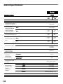
Owner's Manual and Instructions
GUARDIAN ® Agricultural Animal Confinement Building Heaters
MODELS
AW250
OUTPUT (Btuh)
250,000
FUEL
All Models are
available in either
L.P. Gas Vapor
Withdrawal or
Natural Gas
Configurations.
Certification by:
Congratulations!
You have purchased the finest agricultural building heater available.
Your new L.B. White heater incorporates the benefits from the most experienced
manufacturer of heating products using state-of-the-art technology.
We, at L.B. White, thank you for your confidence in our products and
welcome any suggestions or comments you may have...call us, toll-free,
at 1-800-345-7200.
ATTENTION ALL USERS
This heater has been tested and evaluated by C.S.A. International in accordance with
ANSI/IAS U.S. LC2-1996 as well as the Canadian Gas Association Standard for Gas
Fired Brooders, CAN1-2.20-M85 and is listed and approved as a direct gas-fired
circulating heater for the heating of agricultural animal confinement buildings. If you
are considering using this product for any application other than its intended use,
then please contact your fuel gas supplier, or the L.B. White Co., Inc.
150-24161
GENERAL HAZARD WARNING
■ Failure to comply with the precautions and instructions provided with this heater, can result in:
— Death
— Serious bodily injury or burns
— Property damage or loss from fire or explosion
— Asphyxiation due to lack of adequate air supply or carbon monoxide poisoning
— Electrical shock
■ Read this Owner’s Manual before installing or using this heater.
■ Only properly-trained service people should repair or install this heater.
■ Save this Owner’s Manual for future use and reference.
■ Owner’s Manuals and replacement labels are available at no charge. For assistance, contact
L.B. White at 800-345-7200.
WARNING
■ Proper gas supply pressure must be provided to the inlet of the heater.
■ Refer to dataplate for proper gas supply pressure.
■ Gas pressure in excess of the maximum inlet pressure specified at the heater inlet can cause
fires or explosions.
■ Fires or explosions can lead to serious injury, death, building damage or loss of livestock.
■ Gas pressure below the minimum inlet pressure specified at the heater inlet may cause
improper combustion.
■ Improper combustion can lead to asphyxiation or carbon monoxide poisoning and therefore
serious injury or death to humans and livestock.
WARNING
Fire and Explosion Hazard
■ Not for home or recreational vehicle use.
■ Installation of this heater in a home or
recreational vehicle may result in a fire or
explosion.
■ Fire or explosions can cause property
damage or loss of life.
WARNING
Fire and Explosion Hazard
■ Keep solid combustibles a safe distance
away from the heater.
■ Solid combustibles include wood or paper
products, feathers, straw, and dust.
■ Do not use the heater in spaces which
contain or may contain volatile or airborne
combustibles.
■ Volatile or airborne combustibles include
gasoline, solvents, paint thinner, dust
particles or unknown chemicals.
■ Failure to follow these instructions may
result in a fire or explosion.
■ Fire or explosions can lead to property
damage, personal injury or loss of life.
2
CONSIGNES DE SECURITE
Ill es interdit d'utiliser des liquides
inflammables ou degageant des vapeurs
inflammables, a proximite de tout appareil
fonctionnant au gaz.
CONSIGNES DE SECURITE
Si vous sentez une odeur de gaz:
1. Ouvrez le fenetres.
2. Ne touchez pas aux interrupteurs
electriques.
3. Eteignez toute flamme nue.
4. Contactez immediatement votre
compangie de gaz.
FOR YOUR SAFETY
Do not store or use gasoline or other
flammable vapors and liquids in the vicinity of
this or any other appliance.
FOR YOUR SAFETY
If you smell gas:
1. Open windows.
2. Don't touch electrical switches.
3. Extinguish any open flame.
4. Immediately call your gas supplier.
Table of Contents
SECTION
PAGE
General Information . . . . . . . . . . . . . . . . . . . . . . . . . . . . . . . . . . . . . . . . . . . . . . . . . . . . . . . . . . . . . . . . . . .3
Heater Specifications . . . . . . . . . . . . . . . . . . . . . . . . . . . . . . . . . . . . . . . . . . . . . . . . . . . . . . . . . . . . . . . . . .4
Safety Precautions . . . . . . . . . . . . . . . . . . . . . . . . . . . . . . . . . . . . . . . . . . . . . . . . . . . . . . . . . . . . . . . . . . . .5
Installation Instructions
General . . . . . . . . . . . . . . . . . . . . . . . . . . . . . . . . . . . . . . . . . . . . . . . . . . . . . . . . . . . . . . . . . . . . . . . . .7
Air Diverter Installation Instructions . . . . . . . . . . . . . . . . . . . . . . . . . . . . . . . . . . . . . . . . . . . . . . . . . .8
Hanging Installation Instructions . . . . . . . . . . . . . . . . . . . . . . . . . . . . . . . . . . . . . . . . . . . . . . . . . . . . .9
Sediment Trap Assembly Instructions . . . . . . . . . . . . . . . . . . . . . . . . . . . . . . . . . . . . . . . . . . . . . . . . .9
Thermostat Installation Instructions . . . . . . . . . . . . . . . . . . . . . . . . . . . . . . . . . . . . . . . . . . . . . . . . .10
Manual Shut-Off Valve, Hose and Regulator Assembly Instructions . . . . . . . . . . . . . . . . . . . . . . . .10
Start-Up Instructions . . . . . . . . . . . . . . . . . . . . . . . . . . . . . . . . . . . . . . . . . . . . . . . . . . . . . . . . . . . . . . . . .11
Shut-Down Instructions . . . . . . . . . . . . . . . . . . . . . . . . . . . . . . . . . . . . . . . . . . . . . . . . . . . . . . . . . . . . . . .11
Variable Heat Output Instructions . . . . . . . . . . . . . . . . . . . . . . . . . . . . . . . . . . . . . . . . . . . . . . . . . . . . . .12
Cleaning Instructions . . . . . . . . . . . . . . . . . . . . . . . . . . . . . . . . . . . . . . . . . . . . . . . . . . . . . . . . . . . . . . . . .13
Maintenance Instructions . . . . . . . . . . . . . . . . . . . . . . . . . . . . . . . . . . . . . . . . . . . . . . . . . . . . . . . . . . . . .13
Electrical Connection and Ladder Diagram . . . . . . . . . . . . . . . . . . . . . . . . . . . . . . . . . . . . . . . . . . . . . . .14
Heater Component Function . . . . . . . . . . . . . . . . . . . . . . . . . . . . . . . . . . . . . . . . . . . . . . . . . . . . . . . . . . .15
Parts Identification
Parts Schematic . . . . . . . . . . . . . . . . . . . . . . . . . . . . . . . . . . . . . . . . . . . . . . . . . . . . . . . . . . . . . . . . .16
Parts List . . . . . . . . . . . . . . . . . . . . . . . . . . . . . . . . . . . . . . . . . . . . . . . . . . . . . . . . . . . . . . . . . . . . . . .17
Warranty Policy . . . . . . . . . . . . . . . . . . . . . . . . . . . . . . . . . . . . . . . . . . . . . . . . . . . . . . . . . . . . . . . . . . . . . .18
Replacement Parts and Service . . . . . . . . . . . . . . . . . . . . . . . . . . . . . . . . . . . . . . . . . . . . . . . . . . . . . . . .18
General Information
This Owner's Manual includes all options and accessories
commonly used on this heater. However, depending on the
configuration purchased, some options and accessories
may not be included.
When calling for technical service assistance, or for other
specific information, always have model number,
configuration number and serial number available. This
information is contained on the dataplate.
This manual will instruct you in the operation and care of
your unit. Have your qualified installer review this manual
with you so that you fully understand the heater and how it
functions.
The gas supply line installation, installation of the heater,
and repair and servicing of the heater requires continuing
expert training and knowledge of gas heaters and should
not be attempted by anyone who is not so qualified. See
page 6 for definition of the necessary qualifications. A
detailed Installation and Service Guide is available, at no
charge, to qualified personnel by contacting the local L.B.
White distributor, dealer or the L.B. White Company.
Contact your local L.B. White distributor or the L.B. White
Co., Inc. for assistance, or if you have any questions about
the use of the equipment or its application.
The L.B. White Co., Inc. has a policy of continuous product
improvement. It reserves the right to change specifications
and design without notice.
3
Heater Specifications
Model
AW250
SPECIFICATIONS
L.P.
Gas
Natural
Gas
Maximum Input (BTUH)
Minimum Input (BTUH)
250,000
160,000
Ventilation Air Required
to Support Combustion
1,050 CFM
Inlet Gas Supply
Pressure Acceptable
at the Inlet of the
Heater for Purpose
of Input Adjustment
13.5 in. W.C.
MAX.
11 in.
W.C.
7 in.
W.C.
10 in.
W.C.
4 in.
W.C.
MAX.
11.58
lbs.
250
cu. ft.
MIN.
7.41
lbs.
160
cu. ft.
MIN.
Burner Manifold Pressure
Fuel Consumption Per
Hour
Ball Bearing
Motor Characteristics
1/3 H.P.
1100 RPM
Electrical Supply
(Volts/Hz/Phase)
Amp Draw
(Starting Amps
Includes Igniter)
115/60/1
STARTING
11.8
CONTINUOUS
OPERATION
4.5
Dimensions (Inches)
LxWxH
Minimum Safe
Distances From
Nearest
Combustible
Materials
Net Weight (lbs.)
Shipping Weight (lbs.)
4
30 3/4 x 18 1/4 x 28 1/4
TOP
SIDES
BACK
BLOWER
OUTLET
GAS
SUPPLY
1 ft. (.3 m)
1 ft. (.3 m)
1 ft. (.3 m)
6 ft. (1.83 m)
L.P. Gas Supply — 6 ft. (1.83 m)
Natural Gas Supply — N/A
116
126
Safety Precautions
WARNING
Asphyxiation Hazard
■ Do not use this heater for heating human living
L.B. White Company to determine combustion air
quarters.
ventilation requirements of the heater.
■ Do not use in unventilated areas.
■ The flow of combustion and ventilation air must not be
obstructed.
■ Lack of proper ventilation air will lead to improper
combustion.
■ Proper ventilation air must be provided to support the
combustion air requirements of the heater being used.
■ Improper combustion can lead to carbon monoxide
poisoning in humans leading to serious injury or death.
Symptoms of carbon monoxide poisoning can include
headaches, dizziness and difficulty in breathing.
■ Refer to the specification section of the heater’s
Owner’s Manual, heater dataplate, or contact the
■ Symptoms of improper combustion affecting livestock
can be disease, lower feed conversion, or death.
FUEL GAS ODOR
LP gas and natural gas have man-m
made odorants added specifically for detection of fuel gas leaks.
If a gas leak occurs, you should be able to smell the fuel gas.
THAT’S YOUR SIGNAL TO GO INTO IMMEDIATE ACTION!
■ Do not take any action that could ignite the fuel gas. Do
not operate any electrical switches. Do not pull any
power supply or extension cords. Do not light matches
or any other source of flame. Do not use your
telephone.
■ Get everyone out of the building and away from the area
immediately.
■ Close all propane (LP) gas tank or cylinder fuel supply
valves, or the main fuel supply valve located at the
meter if you use natural gas.
■ Propane (LP) gas is heavier than air and may settle in
low areas. When you have reason to suspect a propane
leak, keep out of all low areas.
■ Natural gas is lighter than air and can collect around
rafters or ceilings.
■ Use your neighbor’s phone and call your fuel gas
supplier and your fire department. Do not re-enter the
building or area.
■ Stay out of the building and away from the area until
declared safe by the firefighters and your fuel gas
supplier.
■ FINALLY, let the fuel gas service person and the
firefighters check for escaped gas. Have them air out
the building and area before you return. Properly
trained service people must repair the leak, check for
further leakages, and then relight the appliance for you.
ODOR FADING -- NO ODOR DETECTED
■ Some people cannot smell well. Some people cannot
smell the odor of the man-m
made chemical added to
propane (LP) or natural gas. You must determine if you
can smell the odorant in these fuel gases.
■ Learn to recognize the odor of propane (LP) gas and
natural gas. Local propane (LP) gas dealers and your
local natural gas supplier (utility) will be more than
happy to give you a scratch and sniff pamphlet. Use it
to become familiar with the fuel gas odor.
■ Smoking can decrease your ability to smell. Being
around an odor for a period of time can affect your
sensitivity to that particular odor. Odors present in
animal confinement buildings can mask fuel gas odor.
■ The odorant in propane (LP) gas and natural gas is
colorless and the intensity of its odor can fade under
some circumstances.
■ If there is an underground leak, the movement of gas
through the soil can filter the odorant.
■ Propane (LP) gas odor may differ in intensity at different
levels. Since propane (LP) gas is heavier than air, there
may be more odor at lower levels.
■ Always be sensitive to the slightest gas odor. If you
continue to detect any gas odor, no matter how small,
treat it as a serious leak. Immediately go into action as
discussed previously.
ATTENTION -- CRITICAL POINTS TO REMEMBER!
■ Propane (LP) gas and natural gas have a distinctive
odor. Learn to recognize these odors. (Reference Fuel
Gas Odor and Odor Fading sections above.
■ Even if you are not properly trained in the service and
repair of the heater, ALWAYS be consciously aware of
the odors of propane (LP) gas and natural gas.
■ If you have not been properly trained in repair and service
of propane (LP) gas and natural gas fueled heaters, then
do not attempt to light heater, perform service or repairs,
or make any adjustments to the heater on propane (LP)
gas or natural gas fuel system.
■ A periodic sniff test around the heater or at the heater’s
joints; i.e. hose, connections, etc., is a good safety
practice under any conditions. If you smell even a small
amount of gas, CONTACT YOUR FUEL GAS SUPPLIER
IMMEDIATELY. DO NOT WAIT!
5
1. Do not attempt to install, repair, or service this heater
or the gas supply line unless you have continuing
expert training and knowledge of gas heaters.
Qualifications for service and installation of this
equipment are as follows:
a. To be a qualified gas heater service person, you
must have sufficient training and experience to
handle all aspects of gas-fired heater installation,
service and repair. This includes the task of
installation, troubleshooting, replacement of
defective parts and testing of the heater. You
must be able to place the heater into a continuing
safe and normal operating condition. You must
completely familiarize yourself with each model
heater by reading and complying with the safety
instructions, labels, Owner’s Manual, etc., that is
provided with each heater.
b. To be a qualified gas installation person, you must
have sufficient training and experience to handle
all aspects of installing, repairing and altering gas
lines, including selecting and installing the proper
equipment, and selecting proper pipe and tank
size to be used. This must be done in accordance
with all local, state and national codes as well as
the manufacturer’s requirements.
2. All installations and applications of L.B. White heaters
must meet all relevant local, state and national
codes. Included are L.P. gas, natural gas, electrical,
and safety codes. Your local fuel gas supplier, a local
licensed electrician, the local fire department or
similar government agencies, or your insurance agent
can help you determine code requirements.
a. For U.S.A. installations and applications:
5. For safety, this heater is equipped with a manual
reset high-limit switch and an air flow switch. Never
operate this heater with any safety device that has
been bypassed. Do not operate this heater unless all
of these features are fully functioning.
6. Do not operate the heater with its door open.
7.
Do not locate fuel gas containers or fuel supply
hoses anywhere near the blower outlet of the heater.
8. Do not block air intakes or discharge outlets of the
appliance. Doing so may cause improper combustion
or damage to heater components leading to property
damage or animal loss.
9. The hose assembly (if provided) shall be visually
inspected on an annual basis. If it is evident there is
excessive abrasion or wear, or if the hose is cut, it
must be replaced prior to the heater being put into
operation. The hose assembly shall be protected
from animals, building materials, and contact with
hot surfaces during use. The hose assembly shall be
that specified by the manufacturer. See parts list.
10. Check for gas leaks and proper function upon heater
installation, before building repopulation or when
relocating.
-- ANSI/NFPA 58, latest edition, Standard for
Storage and Handling of Liquefied Petroleum
Gas and/or
11. This heater should be inspected for proper operation
by a qualified ser vice person before building
repopulation and at least annually.
-- ANSI Z223.1/NFPA 54, National Fuel Gas
Code
12. Always turn off the gas supply to the heater if the
heater is not going to be used in the heating of
livestock.
-- ANSI/NFPA 70, National Electrical Code.
b. For Canadian Installations and Applications:
-- CAN1-B149.1 or CAN1-B149.2 Installation
Codes
-- CSA C22.1 Par t 1 Standard Canadian
Electrical Code. CSA C22.2 No. 3, Electrical
Features of Fuel-Burning Equipment.
3. Do not move, handle, or service heater while in
operation or connected to a power or fuel supply.
6
4. This heater may be installed in areas subject to
washdown. This heater may only be washed on the
external case assembly—see Cleaning Instructions.
Do not wash the interior of the heater. Use only
compressed air, soft brush or dry cloth to clean the
interior of the heater and it’s components. After
external washdown, do not operate this heater until it
is completely dry. In any event, do not operate the
heater for at least one hour after external washdown.
13. This heater is equipped with a three-prong
(grounding) plug for your protection against shock
hazard and must be plugged directly into a properly
grounded three-prong receptacle. Failure to use a
properly grounded receptacle can result in electrical
shock, personal injury, or death.
14. Hot surface ignition heaters will make up to three
trials for ignition. If ignition is not achieved after the
third trial, the control system will lock out the gas
control valve. If gas is smelled after system lock out
has occurred, immediately close all fuel supply
valves. Do not relight until you are sure that all gas
that may have accumulated has cleared away. In any
event, do not relight for at least 5 minutes.
15. In a hanging type installation, rigid pipe or copper
tubing coupled directly to the heater may cause gas
leaks during movement, and therefore must not be
used. Use only gas hose assemblies that are rated
and approved for L.P.gas and natural gas in a hanging
type of installation.
16. Installations not using the gas hose supplied with
this appliance must connect dimensionally using
American National Standard Wrought Steel and
Wrought Iron Pipe B36/10-1970. (Aluminum piping
or tubing shall not be used.) Copper tubing when
used for conveying natural gas, shall be internally
tinned or equivalently treated to resist sulphur.
Installation Instructions
GENERAL
WARNING
Fire or explosion hazard.
Can cause property damage, severe injury or death.
1. Disconnect power supply before wiring to prevent
electrical shock or equipment damage.
2. To avoid dangerous accumulation of fuel gas, turn off
gas supply at the heater service valve before starting
installation, and perform gas leak test after
completion of installation.
3. Do not force the gas control knob. Use only your
hand to turn the gas control knob. Never use any
tools. If the knob will not operate by hand, the
control should be replaced by a qualified service
technician. Force or attempted repair may result in
fire or explosion.
1. Read all safety precautions and follow L. B. White
recommendations when installing this heater. If
during the installation or relocating of heater, you
suspect that a part is damaged or defective, call a
qualified service agency for repair or replacement.
2. Make sure the heater is properly positioned before use
and is hung level. Observe and obey all minimum safe
distances of the heater to the nearest combustible
materials. Minimum safe distances are given on the
heater nameplate and on page 4 of this manual.
3. For heaters intended for outdoor installation, the
heater is to be installed at least 18 inches above the
ground or to a height that would prevent snow
blockage of heater’s air inlet.
4. The heater may be used either indoors or outdoors.
When the heater is mounted outdoors, use only the
ductwork supplied in the outdoor mounting kit.
5. The heater must have the proper gas regulator installed
for the application. A regulator must be connected to
the gas supply so that gas pressure at the inlet to the
gas valve is regulated within the range specified on the
dataplate at all times. Contact your gas supplier, or the
L.B. White Co., Inc. if you have any questions.
6. The heater’s gas regulator (with pressure relief valve)
should be installed outside of building. Any
regulators inside the buildings must be properly
vented to the outside. Local, state and national
codes always apply to regulator installation. Natural
gas regulators with vent limiting device may be
mounted indoors without venting to outdoors.
7.
All gas pressure regulators must be installed in strict
accordance with the manufacturer’s safety instructions.
These instructions accompany each regulator.
8. Insure that all accessories that ship within the heater
have been removed from inside of heater and
installed. This per tains to air diver ters, hose,
regulators, etc.
9. Make certain that a sediment trap is installed at the
gas valve inlet to prevent foreign materials (pipe
compound, pipe chips and scale) from entering the
gas valve. Debris blown into the gas valve may cause
that valve to malfunction resulting in a serious gas
leak that could result in a possible fire or explosion
causing loss of products, building or even life. A
properly installed sediment trap will keep foreign
materials from entering the gas valve and protect the
safe functioning of that important safety component.
10. Any heater connected to a piping system must have
an accessible, approved manual shut off valve
installed within six feet (6 ft.) of the appliance it
serves.
11. Check all connections for gas leaks using approved
gas leak detectors. Gas leak testing is performed as
follows:
-- Check all pipe connections, hose connections,
fittings and adapters upstream of the gas
control with approved gas leak detectors.
-- In the event a gas leak is detected, check the
components involved for cleanliness and
proper application of pipe compound before
further tightening.
-- Furthermore tighten the gas connections as
necessary to stop the leak.
-- After all connections are checked and any
leaks are stopped, turn on the main burner.
-- Stand clear while the main burner ignites to
prevent injury caused from hidden leaks that
could cause flashback.
-- With the main burner in operation, check all
connections, hose connections, fittings and
joints as well as the gas control valve inlet and
outlet connections with approved gas leak
detectors.
-- If a leak is detected, check the components
involved for cleanliness in the thread areas
and proper application of pipe compound
before further tightening.
7
-- Tighten the gas connection as necessary to
stop the leak.
-- If necessary, replace the parts or components
involved if the leak cannot be stopped.
-- Ensure all gas leaks have been identified and
repaired before proceeding.
12. A qualified service agency must check for proper
operating gas pressure upon installation of the
heater.
13. Light according to instructions on heater or within
owner's manual.
14. It is extremely important to use the proper size and
type of gas supply line to assure proper functioning of
the heater. Contact your fuel gas supplier for proper
line sizing and installation.
15. This heater can be configured for use with either L.P.
gas vapor withdrawal or natural gas. Consult the
dataplate for the gas configuration of the specific
heater. Do not use the heater in an L.P. liquid
withdrawal system or application. If you are in doubt,
contact the L.B. White Co., Inc.
16. Eventually, like all electrical/mechanical devices, the
thermostat can fail. Thermostat failure may result in
either an underheating or overheating condition
which may damage critical products and/or cause
animal injury or death. Critical products and/or
animals should be protected by a separate back-up
control system that limits high and low temperatures
and also activates appropriate alarms.
17. Take time to understand how to operate and maintain
the heater by using this Owner’s Manual. Make sure
you know how to shut off the gas supply to the
building and also to the individual heater. Contact
your fuel gas supplier if you have any questions.
18. Any defects found in performing any of the service or
maintenance procedures must be eliminated and
defective parts replaced immediately. The heater
must be retested by properly qualified service
personnel before placing the heater back into use.
19. Do not exceed input rating stamped on the dataplate
of the heater. Do not exceed the burner manifold
pressure stated on the dataplate. Do not use an
orifice size different than specified for the specific
input rating of this heater, fuel type configuration and
altitude.
AIR DIVERTER
INSTALLATION INSTRUCTIONS
(Optional accessory on some models.)
(Appearance of the outlet on heater may vary from model to model.)
1. Optional air diverters can be installed in the heater
outlet to provide direction to the heated air as it exits
the heater. Installation options include installing the
diverters in such a way as to broadly distribute the air
in two 45 degree paths or to focus the air flow in one
45 degree direction. See Fig. 1.
FIG. 1 (Typical installation allowing two directions of air movement.)
NOTCHES IN MOUNTING TABS
TABS
OUTLET
SCREWS
2. The air diverters may require hand forming prior to
installation. Make 90 degree bends utilizing the
performations provided. Diverter should then have
the shape shown in Fig. 1.
3. The air diverter’s tabs on each half will pop into the
blower outlet between the inside of the case
assembly and the blower housing outlet. If the
notched tabs do not pop into the blower outlet,
loosen the blower outlet screws. Doing this provides
a gap into which you can insert the tabs. Retighten
the screws after installation.
FORMED
OUTLET GUARD
DIVERTER
HALVES
Alternate Air Diverter Installations
8
HANGING INSTRUCTIONS
FIG. 2
EYEBOLT
CHAIN
FIG. 3
NOTE: REGULATORS SHOULD ALWAYS BE MOUNTED OUTDOORS. IF
CIRCUMSTANCES FORCE INSTALLING THE REGULATOR INDOORS,
THE REGULATOR'S VENT MUST BE VENTED OUTDOORS USING VENT
LINE NO SMALLER THAN VENT OPENING.
VENT OF REGULATOR MUST
POINT DOWN AND REGULATOR
MUST BE VENTED OUTDOORS
MANUAL SHUT-OFF VALVE
CAN BE INSTALLED BEFORE
THE REGULATOR, UNDER
THE EAVE OF THE BUILDING,
OR AFTER THE REGULATOR
INSIDE THE BUILDING.
NUT
CHA
FLAT WASHER
CAGE NUT
IN O
R CA
BLE
OPTIONAL INDOOR
REGULATOR
MOUNTING LOCATION
CASE TOP
2. Be sure heater is securely fastened and is hanging
level. (Check crosswise and lengthwise.) Chain must
be at center of eyebolt for proper heater suspension.
BLACK PIPE
THROUGH WALL
GAS HOSE
THERMOSTAT
CORD
3. See Fig. 3 for typical indoor installation. In any
animal confinement building, consideration must be
given to making sure the heater is located away from
the livestock so that livestock cannot knock the
heater, tear it loose from its mounting, or damage the
heater or its gas supply line in any way. Make sure
you observe and obey minimum clearance distances
to combustible materials as stated in the
specification section of this owner’s manual and on
the heater itself.
VENT LINE
WALL
1. Assemble according to the illustration and tighten all
eyebolts securely. (See Fig. 2):
HEATER
YOKE
WALL OUTLET
POWER CORD
THERMOSTAT
1 FT.
1 FT.
SEDIMENT
TRAP
SEDIMENT TRAP ASSEMBLY
Assemble the tee, nipples and cap together and tighten
securely. See Fig. 4. The sediment trap assembly must
always be mounted in a vertical position. Make sure pipe
thread compound that is resistant to both L.P. gas and
natural gas is used in making all connections.
FIG. 4
NIPPLE
HOSE ADAPTER
TO GAS CONTROL
VALVE INLET
TEE
NIPPLE
CAP
9
THERMOSTAT INSTALLATION
WARNING
Electrical Shock Hazard
■ Disconnect the electrical supply before connecting the
thermostat to the heater.
■ Failure to follow this warning can result in electrical
shock, leading to personal injury or death.
1. To Connect the Series Tap Plug Thermostat Kit:
a. Connect the power cord of the heater to the
female side of the plug on the end of the
thermostat cord.
b. Plug the male side of the series tap plug on the
thermostat cord into a three-wire (grounded)
electrical outlet within the building.
2. To Connect the Direct Wired Thermostat Kit to the
Control Box on the Heater:
a. The installation and wiring of a thermostat must
be done by an electrician or someone properly
qualified.
b. The thermostat may use 18 gauge, 2 wire cord to
handle the low voltage being supplied to the
thermostat from the transformer.
c. Follow all instructions provided with the
thermostat kit.
d. The heater must be tested for proper operation
after the thermostat has been connected.
MANUAL SHUT-OFF VALVE, HOSE
AND REGULATOR ASSEMBLY
2. Assemble the components together according to the
figure. This view is to show general assembly of the
components only. The regulator must always be
mounted so its vent, regardless of location on the
regulator, is always pointed downward.
3. Tighten all connections securely.
FIG. 5
REGULATOR
REGULATOR VENT
GAS FLOW
1. Always use approved pipe thread compound suitable
for use with L.P. gas or natural gas on the threaded
connections.
NIPPLE
VALVE, MANUAL
SHUT-OFF
GAS HOSE
ADAPTER
TO CONTROL
VALVE INLET
10
SEDIMENT TRAP
Start-Up Instructions
contained within the control enclosure. On the HSI
module is a red light emitting diode (LED). This LED
indicates the status of the heater. The LED is visible
external of the control enclosure through the plastic
eye. A constant light from the LED is an indicator that
the heater is functioning correctly. Any flash pattern
by the LED is indicative that there is a problem in the
operation of the heater. Refer to the troubleshooting
decal on the access panel at the fan motor end of the
heater for assistance in troubleshooting. Only
qualified and properly trained personnel shall service
or repair the heater.
Follow steps 1 - 6 on initial start-up after heater installation
by a qualified gas heater service person. For normal startup, simply turn thermostat above room temperature. The
heater will start.
1.
Open all manual fuel supply valves and check for gas
leaks using approved leak detectors. The gas control
valve on the heater has a manual shut-off feature
incorporated into the valve assembly and may be
located under a metal cover. Remove the metal cover
and make sure the indicator on the valve is turned to
the on position. Replace the metal cover. See Fig. 6.
FIG. 6
5.
ON
NOTE:
OFF
2.
Connect the electrical cord to an approved electrical
outlet.
3.
Set the thermostat to desired room temperature.
4.
This heater includes a hot surface ignition (HSI)
control module for purposes of controlling the timing
of the ignition process of the heater as well as
monitoring of the safety functions. The HSI module is
On a call for heat, the motor will start up and run for
five (5) seconds and then stop. This pre-purge is a
safety feature and a normal operational
characteristic prior to ignition taking place. After the
motor has stopped, the igniter will heat up
(approximately 17 seconds). After igniter warm up
time has been achieved, the motor will start again
and shortly thereafter ignition will occur.
6.
It is normal for air to be trapped in the gas
hose on new installations. The heater may
attempt more than one trial for ignition
before the air is finally purged from the line
and ignition takes place.
The HSI control will make up to three trials for
ignition. Each trial for ignition will take approximately
20 seconds. The first two trials for ignition will occur
within 40 seconds if ignition is not achieved. A 15
minute wait period will then begin after the second
trial for ignition has taken place. After the 15 minute
time span has elapsed, the third and final trial for
ignition will take place. If ignition is not achieved at
this final trial, the system will lock out, and a three
flash pattern will be indicated by the LED.
Shut-Down Instructions
If the heater is to be shut down for cleaning, maintenance or
repair, follow steps 1 - 5. Otherwise, simply turn thermostat
to off or no heat for standard shut down.
1. Close all manual fuel supply valves.
2. With the heater lit, allow heater to burn off excess
fuel in gas supply hose.
11
3. Position the indicator on the gas control to off.
4. Position thermostat to off or no heat position.
5. Disconnect the heater from the electrical supply.
Variable Heat Output
1. Some models of propane (LP) gas or natural gas
heaters have a throttle valve for varying heat output
located between the gas control valve and gas
manifold assemblies. THIS IS NOT A MANUAL GAS
SHUT OFF VALVE.
2. The throttle valve can be adjusted to deliver either
minimum heat or maximum heat. When the throttle
FIG. 7
valve handle is parallel to the gas flow, the valve is
completely open to deliver maximum heat output.
(Refer to Fig. 7.)
The throttle valve may be adjusted to minimum heat
output by turning the handle 90° to gas flow or any
position between maximum and minimum settings.
(Refer to Fig. 8.).
FIG. 8
THROTTLE
VALVE
GAS
MANIFOLD
MAXIMUM HEAT
90%
75
OF
MA
XIM
%
UM
OF
UM
XIM
MA
12
MINIMUM HEAT
GAS CONTROL
VALVE
Cleaning Instructions
WARNING
Fire, Burn, and Explosion Hazard
■ This heater contains electrical and mechanical components in the gas management, safety and airflow systems.
■ Such components may become inoperative or fail due to dust, dirt, wear, aging, or the corrosive atmosphere of an
animal confinement building.
■ Periodic cleaning and inspection as well as proper maintenance are essential to avoid serious injury or property
damage.
1. Before cleaning, close fuel supply valve to heater and
disconnect electrical supply.
2. The heater should have dir t or dust removed
periodically:
a. Af ter each flock or between building repopulation, give the heater a general cleaning
using compressed air or a soft brush on its
interior and exterior. At this time, dust off the
motor case to prevent the motor from over-heating
and shutting the heater down.
b. At least once a year, give the heater a thorough
cleaning. At this time, remove the fan and motor
assembly and brush or blow off the fan wheel,
giving attention to the individual fan blades.
Additionally, make sure the burner air inlet venturi
ports and the throat of the casting are free of
dust accumulation and the area between the heat
chamber top and inside case is also free of dust.
c. When washing with water, observe and obey the
Warning within these Cleaning Instructions. This
same Warning is also supplied on the heater.
WARNING
This heater may be washed only on the external case
assembly provided:
A.
The heater is disconnected from the electrical
supply.
B.
All access panels are securely closed.
C.
Water spray nozzle shall not discharge within 6 feet
of the heater.
D.
The water pressure does not exceed 45 PSIG for 10
seconds on each side of heater.
E.
The heater is not reconnected to electrical supply for
a minimum of 1 hour or until the heater is
thoroughly dry.
Improper cleaning of the heater can cause severe
personal injury or property damage due to water and/or
cleaning solution:
1.
In electrical components, connections and wires
causing electrical shock or component failure.
2.
On gas control components causing corrosion which
can result in gas leaks and fire or explosion from the
leak.
Clean internal components of the heater with a soft, dry
brush or cloth, or compressed air.
Maintenance Instructions
1. Have your gas supplier check all gas piping annually
for leaks or restrictions in gas lines. Also, at this time
have your gas supplier clean out the sediment trap of
any debris that may have accumulated.
2. The heater’s surrounding area shall be kept clear and
free from combustible materials, gasoline, and other
flammable vapors and liquids.
3. Regulators can wear out and function improperly.
Have your gas supplier check the date codes on all
regulators installed and check delivery pressures to
the appliance to make sure that the regulator is
reliable.
4. Regulators must be periodically inspected to make
sure the regulator vents are not blocked. Debris,
insects, insect nests, snow, or ice on a regulator can
block vents and cause excess pressure at the
appliance.
5. Review all heater markings (ie. warnings, startup/shutdown, electrical wiring, diagrams, etc.) for
legibility. Ensure that none are cut, torn, or otherwise
damaged. Any damaged markings must be replaced
immediately by contacting L.B. White Co., Inc.
Markings are available at no cost.
13
Electrical Connection and Ladder Diagram
CAUTION
Always refer to the heater’s electrical connection diagram when servicing to avoid wiring errors and heater malfunction.
Check for proper operation after servicing.
WARNING: THIS HEATER MAY START AT ANY TIME
L.E.D. INDICATOR
IGNITER
HIGH LIMIT
SWITCH(ES)
RED
RED
BLUE
BLUE
GREEN
GREEN
AIR PROVING
SWITCH
HEAT CHAMBER
OR
BURNER GROUND
PURPLE WHITE
WHITE
BROWN
FAN
MOTOR
BLACK
BLACK
BLACK
RED
RED
WHITE
YELLOW
BLUE
PURPLE
BROWN
BLUE
GREEN
GREEN
WHITE
WHITE
WHITE
BLACK
BLACK
GREEN
BLACK
YELLOW
IND
L1
HSI
HSIG
L2
W
PSI
FSI
GV
PSO
FSG
C
HSI CONTROL
FLAME
SENSOR
BROWN
TRANSFORMER
WHITE
GREEN
GAS CONTROL VALVE
* THERMOSTAT
BLACK
GREEN
BROWN
GROUND
WHITE
WHITE
BLACK
BLACK
ELECTRICAL CONNECTION DIAGRAM
L1
MOTOR
* THERMOSTAT
24V
TRANSFORMER
120V
NEUTRAL
AIR PROVING
SWITCH
FLAME
SENSOR
BURNER
GROUND
IND
L1
HSI
HSIG
L2
W
PSI
FSI
GV
PSO
FSG
C
HSI CONTROL
SOLENOID(S)
NEUTRAL
HIGH LIMIT
SWITCH
L.E.D. INDICATOR
GROUND
ELECTRICAL LADDER DIAGRAM
IF ANY OF THE ORIGINAL WIRE AS SUPPLIED WITH THE HEATER MUST BE REPLACED,
IT MUST BE REPLACED WITH WIRING HAVING A TEMPERATURE RATING OF AT LEAST 302O F. (150O C.)
14
Heater Component Function
Air Proving Switch
Safety device used to insure that the proper air flow is being
achieved before the gas valve is opened.
Burner
Cast iron component used to channel gas and provide an
area at which the fuel may ignite.
Burner Orifice
Brass metering device used to feed gas to burner at a
specific rate.
Fan Housing
Chamber used for compressing air for ef ficient air
movement.
Fan Wheel
Component used in conjunction with the motor and fan
housing to pull the hot air from heater and blow it into room
for heating (also known as a squirrel cage).
Flame Sensor
Also known as a flame rod or flame probe, this device works
in conjunction with the ignition module in proving that
burner flame has been established.
Gas Control Valve
A device which consists of a low pressure regulator and
electrical solenoids which are used for the control of gas
flow to the burner assembly. A feature of the control is a
built in gas shut off which is used to isolate the heater from
its gas supply when servicing.
Gas Hose
Flexible connector used to convey gas from supply line in
building to heater.
Heat Chamber
Metal fire box within the appliance that provides an area
where burner flame mixes with combustion air thereby
providing heat.
Hot Surface Igniter
Electrical ignition device used on automatic ignition control
systems. Ignites gas by surface temperature rather than by
spark or flame.
Ignition Control Module
Controls the ignition sequence and operation of the heater
as well as monitoring the safety sevices. A major service
feature is the board’s ability to diagnose component and
flame failure by means of a diagnostic light located within
the module. This light will provide a specific flash pattern
repetitively, depending on the type of componenet failure
that has occurred.
Motor
Electric device used to force preheated air through the
heater and to circulate heat within a certain area. Converts
electrical energy into mechanical energy.
Regulator
The heart of any gas supply installation. Used to deliver a
working pressure to the heater under varying conditions in
tank pressure.
Thermostat
Electrical device used as an automatic on/off switch which
will respond to changes in temperature in a certain area.
Can be wired so contacts in the thermostat open or close on
temperature increase or decrease.
Throttle Valve
Manually adjustable component used to increase or
decrease the flow of gas to the burner. The throttle valve is
located between the gas control valve and burner assembly.
Transformer
This device is responsible for reducing a higher incoming
voltage (normally 120 V.A.C.) to a lower outgoing voltage.
The lower voltage (24 V.A.C.) is essential to operate the
ignition control module.
High Limit Switch
Safety device wired into the control system which is used to
break an electrical circuit to the gas control valve in event of
overheat situation.
15
Parts Identification
Parts Schematic
26
27
30
29
31
28
33
32
34
35
24
23
36
22
37
21
19
40
18
15
17
20
7
14
39
1
8
16
2
3
4
9
13
40
12
41
38
5
4
10
11
6
16
Parts Identification
Parts List
Item
1
2
3
4
5
6
7
8
9
10
11
12
13
14
15
16
17
18
19
20
21
22
23
24
26
27
28
29
30
31
32
33
34
35
36
37
38
39
40
41
Description
Part Number
Regulator, LP Gas, 2nd Stage, Vent Over Outlet
Regulator, LP Gas, 2nd Stage, Vent Over Side
Regulator, Natural Gas
Nipple, 3 1/2 in.
Valve, Manual Shut Off
Adapter, Hose, 1/2 NPT x 1/2 NPS
Hose, 1/2 in. ID x 10 ft. with Adapter
Kit, Sediment Trap
Base
Cover, Gas Control Valve
Bracket, Gas Control Valve
Valve, Gas Control: LP Gas
Valve, Gas Control: Natural Gas
Nipple, 1/2 in. x 1 1/2 in.
Valve, Throttle: LP Gas
Valve, Throttle: Natural Gas
Ell, Street
Manifold
Orifice, Burner: LP Gas
Orifice, Burner: Natural Gas
Igniter
Shield, Igniter
Sensor, Flame
Bracket, Igniter
Burner
Spacer
Switch, High Limit
Chamber, Heat
Case, Assembly with Doors and Latches (3)
Galvanized
Painted
Control, Ignition
Transformer, 120/24 v.
Plug, Window
O-Ring
Cover, Control Box
Cord, Power, 10 ft.
Harness, Wire
Motor, 1/3 HP, Ball Bearing
Mount, Motor
Wheel, Fan
Assembly, Air Flow Switch
Housing, Fan, with Air Flow Switch Assembly and Motor Mount
Bolt
Screw, 6 - 32 x 3/4 in.
Screw
Washer
06553
06665
23360
07148
05548
02894
20714
00815
20136
09287
09506
22076
09428
02420
20143
20144
01359
09291
20141
20142
09201
09167
20139
09202
03453
02687
05566
20024
20149
20465
09298
09615
08255
08347
20134
20133
23700
20169
08647
09050
24157
24167
02692
07240
02688
01589
(1) Complete control box assembly, specify part #24235 (galvanized) or 24236 (painted) and if required for U.S.A. or Canada.
(2) For fixed rate heater, replace items 11, 12 and 13 with a 1/2 in. elbow, part #01426 and a nipple, 1/2 in. x 3 1/2 in.,
part #07148.
(3) Specify fuel type and if required for U.S.A. or Canada when ordering.
17
Warranty Policy
HEATER
L.B. White Co., Inc. warrants that the component parts of its
heater are free from defects in material and workmanship,
when properly installed, operated, and maintained in
accordance with the Installation and Maintenance
Instructions, safety guides and labels contained with each
unit. If, within 12 months from the date of purchase by the
end user, any component is found to be defective, L.B.
White Co., Inc. will at its option, repair
or replace the defective part or heater, with a new part or
heater, F.O.B., Onalaska, Wisconsin.
A warranty card on file at L.B. White will automatically
qualify a unit and its component par ts for warranty
consideration. If a warranty card is not on file, a copy of the
bill of sale will be required to establish warranty
qualification. If neither is available, the warranty period will
be 12 months from date of shipment from L B. White.
PARTS
L.B. White Co., Inc. warrants that replacement parts
purchased from the company and used on the appropriate
L. B. White equipment are free from defects both in material
and workmanship for 12 months from the date of purchase
by the end user. Warranty is automatic if a component is
found defective within 12 months of the date code marked
on the part. If the defect occurs more than 12 months later
than the date code but within 12 months from the date of
purchase by the end user, a copy of a bill of sale will be
required to establish warranty qualification.
The warranty set forth above is the exclusive warranty
provided by L.B. White, and all other warranties, including
any implied warranties or merchantability or fitness for a
particular purpose, are expressly disclaimed. In the event
any implied warranty is not hereby effectively disclaimed
due to operation of law, such implied warranty is limited in
duration to the duration of the applicable warranty stated
above. The remedies set forth above are the sole and
exclusive remedies available hereunder. L.B. White will not
be liable for any incidental or consequential damages
directly or indirectly related to the sale, handling or use of
the equipment, and in any event L.B. White's liability in
connection with the equipment, including for claims based
on negligence or strict liability, is limited to the purchase
price.
Some states do not allow limitations on how long an implied
warranty lasts, so the above limitation may not apply to you.
Some states do not allow the exclusion or limitation of
incidental or consequential damages, so the above
limitation or exclusion may not apply to you. This warranty
gives you specific legal rights, and you may also have other
rights which vary from state to state.
Replacement Parts and Service
Contact your local L.B. White dealer for replacement parts
and service or call the L.B. White Co., Inc. at 1-800-345-7200
18
for assistance. Be sure that you have your heater model
number and configuration number when calling.