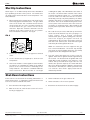
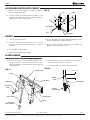
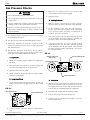
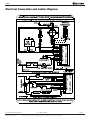
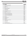
1
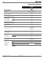
User Manual
GB65
GB65
Air Heater
HC/MSA/UmGB-1589-08/09, ©Munters Europe AB 2008
GB65
Disclaimer
Munters reserves the right to make alterations to specifications, quantities, dimensions etc. for production or
other reasons, subsequent to publication.
The information contained herein has been prepared by qualified experts within Munters.
While we believe the information is accurate and complete, we make no warranty or representation for any particiular
purposes. The information is offered in good faith and with the understanding that any use of the units or accessories in
breach of the directions and warnings in this document is at the sole discretion and risk of the user.
Agricultural Confinement Building Heaters
Agricultural confinement building heaters are intended only for installation in farm buildings used for confignment
of poultry and livestock and which are not used as human workplaces for periods in excess of 4 hours per day. This
type of heater is not intended for use in other types of buildings including those used for human dwelling, grain
storage or grain handling or where gasoline or other liquids having flammable vapors are stored or used.
Refer to the ventilation requirements for agricultural confinement buildings in this manual.
Agricultural Building Heaters
Agricultural building heaters are intened only for installation in farm buildings excluding those used for human
dwelling, grain storage or grain handling, or where gasoline or other liquids having flammable vapors are stored
or used.
Refer to the ventilation requirements for agricultural building heaters in this manual.
HC/MSA/UmGB-1589-08/09
©Munters Europe AB 2008
User Manual GB65
Munters reserves the right to make alterations to specifications, quantities, etc. for production or other reasons, subsequent to publication.
1(1)
GB65
Table of Contents
PAGE
SECTION
General Information . . . . . . . . . . . . . . . . . . . . . . . . . . . . . . . . . . . . . . . . . . . . . . . . . . . . . . . . . . . . . . . . . . .3
Heater Specifications . . . . . . . . . . . . . . . . . . . . . . . . . . . . . . . . . . . . . . . . . . . . . . . . . . . . . . . . . . . . . . . . . .4
Safety Precautions . . . . . . . . . . . . . . . . . . . . . . . . . . . . . . . . . . . . . . . . . . . . . . . . . . . . . . . . . . . . . . . . . . . .5
Installation Instructions
General . . . . . . . . . . . . . . . . . . . . . . . . . . . . . . . . . . . . . . . . . . . . . . . . . . . . . . . . . . . . . . . . . . . . . . . . .7
Air Diverter Installation Instructions . . . . . . . . . . . . . . . . . . . . . . . . . . . . . . . . . . . . . . . . . . . . . . . . . .9
Hanging Instructions . . . . . . . . . . . . . . . . . . . . . . . . . . . . . . . . . . . . . . . . . . . . . . . . . . . . . . . . . . . . . . .9
Sediment Trap Assembly . . . . . . . . . . . . . . . . . . . . . . . . . . . . . . . . . . . . . . . . . . . . . . . . . . . . . . . . . .10
Thermostat Installation . . . . . . . . . . . . . . . . . . . . . . . . . . . . . . . . . . . . . . . . . . . . . . . . . . . . . . . . . . .10
Manual Shut-Off Valve, Hose and Regulator Assembly . . . . . . . . . . . . . . . . . . . . . . . . . . . . . . . . . .10
Start-Up Instructions . . . . . . . . . . . . . . . . . . . . . . . . . . . . . . . . . . . . . . . . . . . . . . . . . . . . . . . . . . . . . . . . .11
Shut-Down Instructions . . . . . . . . . . . . . . . . . . . . . . . . . . . . . . . . . . . . . . . . . . . . . . . . . . . . . . . . . . . . . . .11
Cleaning Instructions . . . . . . . . . . . . . . . . . . . . . . . . . . . . . . . . . . . . . . . . . . . . . . . . . . . . . . . . . . . . . . . . .12
Maintenance Instructions . . . . . . . . . . . . . . . . . . . . . . . . . . . . . . . . . . . . . . . . . . . . . . . . . . . . . . . . . . . . .12
Service Instructions
General . . . . . . . . . . . . . . . . . . . . . . . . . . . . . . . . . . . . . . . . . . . . . . . . . . . . . . . . . . . . . . . . . . . . . . . .13
Motor and Fan Wheel Assembly . . . . . . . . . . . . . . . . . . . . . . . . . . . . . . . . . . . . . . . . . . . . . . . . . . . .13
Air Proving Switch with Paddle . . . . . . . . . . . . . . . . . . . . . . . . . . . . . . . . . . . . . . . . . . . . . . . . . . . . . .14
Igniter . . . . . . . . . . . . . . . . . . . . . . . . . . . . . . . . . . . . . . . . . . . . . . . . . . . . . . . . . . . . . . . . . . . . . . . . . .14
Flame Sensor . . . . . . . . . . . . . . . . . . . . . . . . . . . . . . . . . . . . . . . . . . . . . . . . . . . . . . . . . . . . . . . . . . .14
Replacing Gas Control Valve . . . . . . . . . . . . . . . . . . . . . . . . . . . . . . . . . . . . . . . . . . . . . . . . . . . . . . .15
Testing the Manual Reset High Limit Switch . . . . . . . . . . . . . . . . . . . . . . . . . . . . . . . . . . . . . . . . . . .15
Gas Pressure Checks . . . . . . . . . . . . . . . . . . . . . . . . . . . . . . . . . . . . . . . . . . . . . . . . . . . . . . . . . . . . .16
Troubleshooting Guide . . . . . . . . . . . . . . . . . . . . . . . . . . . . . . . . . . . . . . . . . . . . . . . . . . . . . . . . . . . . . . . .17
Electrical Connection and Ladder Diagram . . . . . . . . . . . . . . . . . . . . . . . . . . . . . . . . . . . . . . . . . . . . . . .24
Heater Component Function . . . . . . . . . . . . . . . . . . . . . . . . . . . . . . . . . . . . . . . . . . . . . . . . . . . . . . . . . . .25
Parts Identification
Parts Schematic . . . . . . . . . . . . . . . . . . . . . . . . . . . . . . . . . . . . . . . . . . . . . . . . . . . . . . . . . . . . . . . . .26
Parts List . . . . . . . . . . . . . . . . . . . . . . . . . . . . . . . . . . . . . . . . . . . . . . . . . . . . . . . . . . . . . . . . . . . . . . .27
Warranty Policy . . . . . . . . . . . . . . . . . . . . . . . . . . . . . . . . . . . . . . . . . . . . . . . . . . . . . . . . . . . . . . . . . . . . .28
Replacement Parts and Service . . . . . . . . . . . . . . . . . . . . . . . . . . . . . . . . . . . . . . . . . . . . . . . . . . . . . . . .28
General Information
This Owner's Manual includes all options and accessories
commonly used on this heater. However, depending on the
configuration purchased, some options and accessories
may not be included.
When calling for technical service assistance, or for other
specific information, always have model number and serial
number available. This information is contained on the
dataplate. The dataplate is located on the exterior of the
case assembly on the blower outlet side of the heater.
This manual will instruct you in the operation and care of
your unit. Have your qualified installer review this manual
with you so that you fully understand the heater and how it
functions.
HC/MSA/UmGB-1589-08/09
©Munters Europe AB 2008
The gas supply line installation, installation of the heater,
and repair and servicing of the heater requires continuing
expert training and knowledge of gas heaters and should
not be attempted by anyone who is not so qualified. See
page 6 for definition of the necessary qualifications.
Contact your local MUNTERS distributor or MUNTERS for
assistance, or if you have any questions about the use of
the equipment or its application.
MUNTERS has a policy of continuous product improvement.
It reserves the right to change specifications and design
without notice.
User Manual GB65
Munters reserves the right to make alterations to specifications, quantities, etc. for production or other reasons, subsequent to publication.
2(2)
GB65
Heater Specifications
Model
GB65
SPECIFICATIONS
Fuel Type
Butane / Propane Gas
Maximum Input (kW)
65.9
Ventilation Air Required
to Support Combustion (m3/hr.)
1590
Inlet Gas Supply
MAX
Pressure Acceptable
at the Inlet of the
Heater for Purpose
MIN.
of Input Adjustment (mbar)
33.6
27.4
Burner Manifold Pressure (mbar)
20.0
Fuel Consumption Per
Hour (kg)
4.73
Motor Characteristics
Ball Bearing
408 WATTS
1290 RPM
Electrical Supply
(Volts/Hz/Phase)
230/50/1
Amp Draw
(Starting Amps
Includes Igniter)
STARTING
6.0
CONTINUOUS
OPERATION
1.7
Dimensions
L x W x H (cm)
93 x 61 x 51
Minimum Safe
Distances From
Nearest
Combustible
Materials
HC/MSA/UmGB-1589-08/09
©Munters Europe AB 2008
TOP
SIDES
BACK
BLOWER
OUTLET
0.3 m.
0.3 m.
0.3 m.
GAS SUPPLY
1.83 m.
3.0 m.
User Manual GB65
Munters reserves the right to make alterations to specifications, quantities, etc. for production or other reasons, subsequent to publication.
3(3)
GB65
Safety Precautions
●
●
●
●
●
●
●
●
●
●
●
GENERAL HAZARD WARNING
Failure to comply with the precautions and
instructions provided with this heater, can result in:
— Death
— Serious bodily injury or burns
— Property damage or loss from fire or explosion
— Asphyxiation due to lack of adequate air supply
or carbon monoxide poisoning
— Electrical shock
Read this Owner’s Manual before installing or using
this heater.
Only properly-trained service people should repair
or install this heater.
Save this Owner’s Manual for future use and
reference.
Owner’s Manuals and replacement labels are
available at no charge.
WARNING
Proper gas supply pressure must be provided to the
inlet of the heater.
Refer to the heater’s dataplate for proper gas supply
pressure.
Gas pressure in excess of the maximum inlet
pressure specified at the heater inlet can cause fires
or explosions.
Fires or explosions can lead to serious injury, death,
building damage or loss of livestock.
Gas pressure below the minimum inlet pressure
specified at the heater inlet may cause improper
combustion.
Improper combustion can lead to asphyxiation or
carbon monoxide poisoning and therefore serious
injury or death to humans and livestock.
IMPORTANT INSTRUCTIONS
●
●
●
●
●
●
●
Supply Cords must be placed or protected so it is not
accessible to animals.
Damaged appliances shall not be used
Heat-radiating appliances shall not be mounted less
than 500mm from animals or inflammable material
Repairs shall be carried out only be a qualified
Munters Technician.
Upon installation, a plug for the disconnection of
appliance from main supply must be provided.
If the supply cord is damaged, it must be replaced by
a qualified Munters Technician to avoid a hazard.
FOR YOUR SAFETY
Do not store or use gasoline or other flammable
vapors and liquids in the vicinity of this or any other
appliance.
- Open windows.
- Don't touch electrical switches.
- Extinguish any open flame.
- Immediately call your gas supplier.
WARNING (Fire and Explosion Hazard)
●
●
●
●
●
●
●
●
●
Not for home or recreational vehicle use.
Installation of this heater in a home or recreational
vehicle may result in a fire or explosion.
Fire or explosions can cause property damage or loss
of life.
Keep solid combustibles a safe distance away from
the heater.
Solid combustibles include wood or paper products,
feathers, straw, and dust.
Do not use the heater in spaces which contain or may
contain volatile or airborne combustibles.
Volatile or airborne combustibles include gasoline,
solvents, paint thinner, dust particles or unknown
chemicals.
Failure to follow these instructions may result in a
fire or explosion.
Fire or explosions can lead to property damage,
personal injury or loss of life.
HC/MSA/UmGB-1589-08/09
©Munters Europe AB 2008
User Manual GB65
Munters reserves the right to make alterations to specifications, quantities, etc. for production or other reasons, subsequent to publication.
4(4)
GB65
WARNING
Asphyxiation Hazard
■ Do not use this heater for heating human living
MUNTERS to determine combustion air ventilation
quarters.
requirements of the heater.
■ Do not use in unventilated areas.
■ The flow of combustion and ventilation air must not be
obstructed.
■ Lack of proper ventilation air will lead to improper
combustion.
■ Proper ventilation air must be provided to support the
combustion air requirements of the heater being used.
■ Improper combustion can lead to carbon monoxide
poisoning in humans leading to serious injury or death.
Symptoms of carbon monoxide poisoning can include
headaches, dizziness and difficulty in breathing.
■ Refer to the specification section of the heater’s
Owner’s Manual, heater dataplate, or contact the
■ Symptoms of improper combustion affecting livestock
can be disease, lower feed conversion, or death.
FUEL GAS ODOR
LP gashas a man-made odorant added specifically for detection of fuel gas leaks.
If a gas leak occurs, you should be able to smell the fuel gas.
THAT’S YOUR SIGNAL TO GO INTO IMMEDIATE ACTION!
■ Do not take any action that could ignite the fuel gas. Do
not operate any electrical switches. Do not pull any
power supply or extension cords. Do not light matches
or any other source of flame. Do not use your
telephone.
■ Get everyone out of the building and away from the area
immediately.
■ Close all propane gas tank or cylinder fuel supply
valves.
■ Propane gas is heavier than air and may settle in low
areas. When you have reason to suspect a propane
leak, keep out of all low areas.
■ Use your neighbor’s phone and call your fuel gas
supplier and your fire department. Do not re-enter the
building or area.
■ Stay out of the building and away from the area until
declared safe by the firefighters and your fuel gas
supplier.
■ FINALLY, let the fuel gas service person and the
firefighters check for escaped gas. Have them air out
the building and area before you return. Properly
trained service people must repair the leak, check for
further leakages, and then relight the appliance for you.
ODOR FADING -- NO ODOR DETECTED
■ Some people cannot smell well. Some people cannot
smell the odor of the man-made chemical added to
propane (LP) gas. You must determine if you can smell
the odorant in this fuel gas.
■ Learn to recognize the odor of propane gas. Local
propane gas dealers will be more than happy to give you
a scratch and sniff pamphlet. Use it to become familiar
with the fuel gas odor.
■ Smoking can decrease your ability to smell. Being
around an odor for a period of time can affect your
sensitivity to that particular odor. Odors present in
animal confinement buildings can mask fuel gas odor.
■ The odorant in propane gas is colorless and the
intensity of its odor can fade under some
circumstances.
■ If there is an underground leak, the movement of gas
through the soil can filter the odorant.
■ Propane gas odor may differ in intensity at different
levels. Since propane gas is heavier than air, there may
be more odor at lower levels.
■ Always be sensitive to the slightest gas odor. If you
continue to detect any gas odor, no matter how small,
treat it as a serious leak. Immediately go into action as
discussed previously.
ATTENTION -- CRITICAL POINTS TO REMEMBER!
■ Propane gas has a distinctive odor. Learn to recognize
this odor. (Reference Fuel Gas Odor and Odor Fading
sections above.
■ Even if you are not properly trained in the service and
repair of the heater, ALWAYS be consciously aware of
the odor of propane gas.
■ If you have not been properly trained in repair and service
of propane gas fueled heaters, then do not attempt to
light heater, perform service or repairs, or make any
adjustments to the heater on a propane gas fuel system.
■ A periodic sniff test around the heater or at the heater’s
joints; i.e. hose, connections, etc., is a good safety
practice under any conditions. If you smell even a small
amount of gas, CONTACT YOUR FUEL GAS SUPPLIER
IMMEDIATELY. DO NOT WAIT!
HC/MSA/UmGB-1589-08/09
©Munters Europe AB 2008
User Manual GB65
Munters reserves the right to make alterations to specifications, quantities, etc. for production or other reasons, subsequent to publication.
5(5)
GB65
Safety Precautions
1. Do not attempt to install, repair, or service this heater
or the gas supply line unless you have continuing
expert training and knowledge of gas heaters.
Qualifications for service and installation of this
equipment are as follows:
a. To be a qualified gas heater service person, you
must have sufficient training and experience to
handle all aspects of gas-fired heater installation,
service and repair. This includes the task of
installation, troubleshooting, replacement of
defective parts and testing of the heater. You
must be able to place the heater into a continuing
safe and normal operating condition. You must
completely familiarize yourself with each model
heater by reading and complying with the safety
instructions, labels, Owner’s Manual, etc., that is
provided with each heater.
b. To be a qualified gas installation person, you must
have sufficient training and experience to handle
all aspects of installing, repairing and altering gas
lines, including selecting and installing the proper
equipment, and selecting proper pipe and tank
size to be used. This must be done in accordance
with all local, state and national codes as well as
the manufacturer’s requirements.
2. All installations and applications of MUNTERS heaters
must meet all relevant local, state and national
codes. Included are L.P. gas, natural gas, electrical,
and safety codes. Your local fuel gas supplier, a local
licensed electrician, the local fire department or
similar government agencies, or your insurance agent
can help you determine code requirements.
3. Do not move, handle, or service heater while in
operation or connected to a power or fuel supply.
9. The hose assembly shall be visually inspected on an
annual basis. If it is evident there is excessive
abrasion or wear, or if the hose is cut, it must be
replaced prior to the heater being put into operation.
The hose assembly shall be protected from animals,
building materials, and contact with hot surfaces
during use. The hose assembly shall be that
specified by the manufacturer. See parts list.
10. Check for gas leaks and proper function upon heater
installation, before building repopulation or when
relocating.
11. This heater should be inspected for proper operation
by a qualified ser vice person before building
repopulation and at least annually.
12. Always turn off the gas supply to the heater if the
heater is not going to be used in the heating of
livestock.
13. This heater is wired for a three-wire electrical system.
There is a hot lead, neutral lead, and a ground lead.
The heater may or may not incorporate a plug in the
power cord on the heater and the plug may or may
not incorporate a pin for the ground wire. In any case,
the heater must be properly connected into a
grounded electrical supply using the ground lead in
the power cord. Failure to use a properly grounded
electrical supply can result in electrical shock,
personal injury, or death.
14. Electronic ignition heaters will make up to three trials
for ignition. If ignition is not achieved after the third
trial, the control system will lock out the gas control
valve. If gas is smelled after system lock out has
occurred, immediately close all fuel supply valves. Do
not relight until you are sure that all as that may have
accumulated has cleared away. In any event, do not
relight the heater for at least 5 minutes.
4. This heater may be installed in areas subject to
washdown. This heater may only be washed on the
external case assembly—see Cleaning Instructions.
Do not wash the interior of the heater. Use only
compressed air, soft brush or dry cloth to clean the
interior of the heater and it’s components. After
external washdown, do not operate the heater until it
is completely dry. In any event, do not operate this
heater for at least one hour after external washdown.
15. In a hanging type installation, rigid pipe or copper
tubing coupled directly to the heater may cause gas
leaks during movement, and therefore must not be
used. Use only gas hose assemblies that are rated
and approved for LP-gas and natural gas in a hanging
type installation.
5. For safety, this heater is equipped with manual reset
high-limit switches and an air flow switch. Never
operate this heater with any safety device that has
been bypassed. Do not operate this heater unless all
of these features are fully functioning.
16. Installations not using the gas hose supplied with this
appliance must connect dimensionally using
American National Standard Wrought Steel and
Wrought Iron Pipe B36/10-1970. (Aluminum piping
or tubing shall not be used.) Copper tubing when
used for conveying natural gas, shall be internally
tinned or equivalently treated to resist sulphur.
6. Do not operate the heater with its door open or panel
removed.
7. Do not locate fuel gas containers or fuel supply hoses
within 6.10 meters of the heater’s blower outlet.
8. Do not block air intakes or discharge outlets of the
appliance. Doing so may cause improper combustion
or damage to heater components leading to property
damage or animal loss.
HC/MSA/UmGB-1589-08/09
©Munters Europe AB 2008
User Manual GB65
Munters reserves the right to make alterations to specifications, quantities, etc. for production or other reasons, subsequent to publication.
6(6)
GB65
Installation Instructions
GENERAL
that valve to malfunction resulting in a serious gas
leak that could result in a possible fire or explosion
causing loss of products, building or even life. A
properly installed sediment trap will keep foreign
materials from entering the gas valve and protect the
safe functioning of that important safety component.
WARNING
Fire or Explosion Hazard.
Can cause property damage, severe injury or death.
■ Disconnect power supply before wiring to prevent
electrical shock or equipment damage.
■ To avoid dangerous accumulation of fuel gas, turn off
gas supply at the appliance service valve before
starting installation, and perform gas leak test after
completion of installation.
■ Do not force the gas control knob. Use only your
hand to turn the gas control knob. Never use any
tools. If the knob will not operate by hand, the
control should be replaced by a qualified service
technician. Force or attempted repair may result in
fire or explosion.
1. Read all safety precautions and follow MUNTERS
recommendations when installing this heater. If
during the installation or relocating of heater, you
suspect that a part is damaged or defective, call a
qualified service agency for repair or replacement.
9. Any heater connected to a piping system must have
an accessible, approved manual shut off valve
installed within 1.83 meters of the heater it serves.
10. Check all connections for gas leaks using approved
gas leak detectors. Gas leak testing is performed as
follows:
WARNING
■
■
■
■
2. Make sure the heater is properly positioned before use
and is hung level. Observe and obey all minimum safe
distances of the heater to the nearest combustible
materials. Minimum safe distances are given on the
heater nameplate and on page 4 of this manual.
Fire and Explosion Hazard
Do not use open flame (matches, torches, candles,
etc.) in checking for gas leaks.
Use only approved leak detectors.
Failure to follow this warning can lead to fires or
explosions.
Fires or explosions can lead to property damage,
personal injury or loss of life.
--
Check all pipe connections, hose connections,
fittings and adapters upstream of the gas
controlwith approved gas leak detectors.
--
In the event a gas leak is detected, check the
components involved for cleanliness and proper
application of pipe compound before further
tightening.
Furthermore tighten the gas connections as
necessary to stop the leak.
After all connections are checked and any leaks
are stopped, turn on the main burner.
Stand clear while the main burner ignites to
prevent injury caused from hidden leaks that
could cause flashback.
With the main burner in operation, check all
connections, hose connections, fittings and joints
as well as the gas control valve inlet and outlet
connections with approved gas leak detectors.
If a leak is detected, check the components
involved for cleanliness in the thread areas and
proper application of pipe compound before
further tightening.
Tighten the gas connection as necessary to stop
the leak.
If necessary, replace the parts or components
involved if the leak cannot be stopped.
Ensure all gas leaks have been identified and
repaired before proceeding.
3. This heater is approved for indoor use only.
4. The heater must have the proper gas regulator
installed for the application. A regulator must be
connected to the gas supply so that gas pressure at
the inlet to the gas valve is regulated within the range
specified on the dataplate at all times. Contact your
gas supplier, or MUNTERS if you have any questions.
--
5. The heater’s gas regulator (with pressure relief valve)
should be installed outside of building. Any regulators
inside the buildings must be properly vented to the
outside. Local, state and national codes always apply
to regulator installation. Natural gas regulators with
vent limiting device may be mounted indoors without
venting to outdoors.
--
6. All gas pressure regulators must be installed in strict
accordance with the manufacturer’s safety
instructions. These instructions accompany each
regulator.
--
---
--
---
7. Insure that all accessories that ship within the heater
have been removed from inside of heater and
installed. This per tains to air diver ters, hose,
regulator, etc.
8. Make certain that a sediment trap is installed at the
gas valve inlet to prevent foreign materials (pipe
compound, pipe chips and scale) from entering the
gas valve. Debris blown into the gas valve may cause
HC/MSA/UmGB-1589-08/09
©Munters Europe AB 2008
11. A qualified service agency must check for proper
operating gas pressure upon installation of the
heater.
12. Light according to instructions on the heater or within
owner’s manual.
User Manual GB65
Munters reserves the right to make alterations to specifications, quantities, etc. for production or other reasons, subsequent to publication.
7(7)
GB65
13. Make sure the heater has the proper gas regulator for
the application. A regulator must be connected to the
gas supply so that gas pressure at the inlet to the gas
valve is regulated within the range specified on the
dataplate at all times. Contact your gas supplier, or,
MUNTERS Heating, if you have any questions.
14. It is extremely important to use the proper size and
type of gas supply line to assure proper functioning of
the heater. Contact your fuel gas supplier for proper
line sizing and installation.
15. This heater can be configured for use with either L.P.
vapor withdrawal or natural gas. Consult the
dataplate, located on the blower outlet side of the
case assembly, for the gas configuration of the
specific heater. Do not use the heater in an L.P. gas
liquid withdrawal system or application. If you are in
doubt, contact MUNTERS.
building and also to the individual heater. Contact
your fuel gas supplier if you have any questions.
18. Any defects found in performing any of the service or
maintenance procedures must be eliminated and
defective parts replaced immediately. The heater
must be retested by properly qualified service
personnel before placing the heater back into use.
19. Do not exceed input rating stamped on the dataplate
of the heater. Do not exceed the burner manifold
pressure stated on the dataplate. Do not use an
orifice size different than specified for the specific
input rating of this heater, fuel type configuration and
altitude.
16. Eventually, like all electrical/mechanical devices, the
thermostat can fail. Thermostat failure may result in
either an underheating or overheating condition
which may damage critical products and/or cause
animal injury or death. Critical products and/or
animals should be protected by a separate back-up
control system that limits high and low temperatures
and also activates appropriate alarms.
17. Take time to understand how to operate and maintain the heater by using this Owner’s Manual. Make
sure you know how to shut off the gas supply to the
HC/MSA/UmGB-1589-08/09
©Munters Europe AB 2008
User Manual GB65
Munters reserves the right to make alterations to specifications, quantities, etc. for production or other reasons, subsequent to publication.
8(8)
GB65
AIR DIVERTER INSTALLATION INSTRUCTIONS
(Appearance of the outlet on heater may vary from model to model.)
1. Air diverters can be installed in the heater outlet to
provide direction to the heated air as it exits the
heater. Refer to Fig. 1. Air diverters can be installed to
direct the air in either two 45 degree paths or in one
45 degree direction.
FIG.1 (Typical installation allowing two directions of air movement.)
NOTCHES IN MOUNTING TABS
TABS
2. The air diverters may require hand forming prior to
installation. Make 90 degree bends utilizing the
perforations provided. The diverter halves should
then have the shape as shown in Fig. 1.
3. The air diverter’s tabs on each half will pop into the
blower outlet between the inside of the case
assembly and the blower housing outlet. If the
notched tabs do not pop into the blower outlet, loosen
the blower outlet screws. Doing this provides a gap
into which you can insert the tabs. Retighten the
screws after installation.
OUTLET
SCREWS
FORMED
OUTLET GUARD
DIVERTER
HALVES
ALTERNATE AIR DIVERTER ARRANGEMENTS
HANGING INSTRUCTIONS
1. Assemble according to Fig.3 and tighten all eyebolts
securely.
2. Be sure heater is securely fastened and is hanging
level. (Check crosswise and lengthwise.)
FIG. 2
NOTE: REGULATORS SHOULD ALWAYS BE MOUNTED OUTDOORS. IF
CIRCUMSTANCES FORCE INSTALLING THE REGULATOR INDOORS,
THE REGULATOR'S VENT MUST BE VENTED OUTDOORS USING VENT
LINE NO SMALLER THAN VENT OPENING.
3. See Fig. 2 for typical indoor installation. In any animal
confinement building, consideration must be given to
making sure the heater is located away from the
livestock so that livestock cannot knock the heater,
tear it loose from its mounting, or damage the heater
or its gas supply line in any way. Make sure you
observe and obey minimum clearance distances to
combustible materials as stated in the specification
section of this owner’s manual and on the heater
dataplate.
FIG. 3
VENT OF REGULATOR MUST
POINT DOWN AND REGULATOR
MUST BE VENTED OUTDOORS
CHA
IN O
MANUAL SHUT-OFF VALVE
CAN BE INSTALLED BEFORE
THE REGULATOR, UNDER
THE EAVE OF THE BUILDING,
OR AFTER THE REGULATOR
INSIDE THE BUILDING.
R CA
BLE
OPTIONAL INDOOR
REGULATOR
MOUNTING LOCATION
BLACK PIPE
THROUGH WALL
GAS HOSE
EYE BOLT
THERMOSTAT
CORD
CHAIN
VENT LINE
WALL
NUT
HEATER
FLAT WASHER
AIR DIVERTER
YOKE
POWER CORD
FLAT WASHER
HEATER TOP
NUT
HC/MSA/UmGB-1589-08/09
©Munters Europe AB 2008
THERMOSTAT
WALL OUTLET
1 FT.
User Manual GB65
Munters reserves the right to make alterations to specifications, quantities, etc. for production or other reasons, subsequent to publication.
1 FT.
SEDIMENT
TRAP
9(9)
GB65
SEDIMENT TRAP ASSEMBLY
Assemble the tee, nipples and cap together and tighten
securely. The sediment trap assembly must always be
mounted in a vertical position. Make sure pipe thread
compound that is resistant to both L.P. and natural gas is
used in making all connections. Check all connections for
gas leaks using approved gas leak detectors.
FIG. 4
NIPPLE
HOSE ADAPTER
TEE
TO GAS CONTROL
VALVE INLET
NIPPLE
CAP
THERMOSTAT INSTALLATION
a. The installation and wiring of a thermostat must
be done by an electrician or someone properly
qualified.
WARNING
Electrical Shock Hazard
■ Disconnect the electrical supply before connecting the
thermostat to the heater.
■ Failure to follow this warning can result in electrical
b. The thermostat may use 18 gauge, 3 wire (with
ground) cord to handle the voltage being supplied
to the thermostat.
shock, leading to personal injury or death.
1.
To Connect the Direct Wired Thermostat Kit to the
Control Box on the Heater:
c. The heater must be tested for proper operation
after the thermostat has been connected.
MANUAL SHUT-OFF VALVE, HOSE
AND REGULATOR ASSEMBLY
1. Always use approved pipe thread compound suitable
for use with L.P. or natural gas on the threaded
connections.
FIG. 5
VALVE, MANUAL
SHUT-OFF
NIPPLE 1/2"
2. Assemble the components together according to the
figure. This view is to show general assembly of the
components only.
PIPING ADAPTER
REGULATOR
3. Tighten all connections securely.
4. Check all connections for gas leaks using approved
gas leak detectors.
REGULATOR VENT
PIPING ADAPTER
GAS FLOW
ADAPTER
GAS HOSE
ADAPTER
TO GAS CONTROL
SEDIMENT TRAP
VALVE INLET
HC/MSA/UmGB-1589-08/09
©Munters Europe AB 2008
User Manual GB65
Munters reserves the right to make alterations to specifications, quantities, etc. for production or other reasons, subsequent to publication.
10(10)
GB65
Start-Up Instructions
Follow steps 1 - 6 on initial start-up after heater installation
by a qualified gas heater service person. For normal startup, simply set the thermostat above room temperature. The
heater will start.
1.
Open all manual fuel supply valves and check for gas
leaks using approved leak detectors. The gas control
valve on the heater has a manual shut-off feature
incorporated into the valve assembly and will be
located within the gas control and electrical
enclosure. Open the enclosure and make sure the
indicator on the valve is turned to the “on” position.
Close and latch the enclosure. See Fig. 6.
emitting diode (LED). This LED indicates the status of
the heater. The LED is visible external of the control
enclosure through the plastic eye. A constant light
from the LED is an indicator that the heater is
functioning correctly. Any flash pattern by the LED is
indicative that there is a problem in the operation of
the heater. Refer to the troubleshooting decal on the
access panel at the fan motor end of the heater for
assistance in troubleshooting. Only qualified and
properly trained personnel shall service or repair the
heater.
5.
FIG. 6
NOTE: It is normal for air to be trapped in the gas
hose on new installations. The heater may attempt
more than one trial for ignition before the air is finally
purged from the line and ignition takes place.
ON
OFF
2.
On a call for heat, the motor will start up and run for
about 6 seconds and then stop. This “pre-purge” is a
safety feature and a normal operational
charactertistic prior to ignition taking place. After the
motor has stopped, the lighter will heat up
(approximately 30 seconds). After igniter warm up
time has been achieved, the motor will start again
and shortly thereafter ignition will occur.
Connect the electrical cord to an approved electrical
outlet.
3.
Set the thermostat (if supplied) to desired room
temperature.
4.
This heater includes a direct ignition control module
for purposes of controlling the timing of the ignition
process of the heater as well as monitoring of the
safety functions. The module is contained within the
metal control box. On the module is a red light
6.
The HSI control will make up to three trials for
ignition. Each trial for ignition will take approximately
45 seconds. The first two trials for ignition will occur
within 90 seconds if ignition is not achieved. A 15
minute wait period will then begin. After the 15
minute time span has elapsed, the control will make
three more trials for ignition. If igntion is not achieved
after after the final trial, the control system will “lock
out” and the “three flash” light pattern will be
indicated by the LED.
Shut-Down Instructions
If the heater is to be shut down for cleaning, maintenance or
repair, follow steps 1 - 5. Otherwise, simply turn thermostat
to off or no heat for standard shut down.
1. Close all manual fuel supply valves.
3. Turn the indicator on the gas control to off.
4. Turn thermostat to off or no heat position.
5. Disconnect the heater from the electrical supply.
2. With the heater lit, allow heater to burn off excess
fuel in gas supply hose.
HC/MSA/UmGB-1589-08/09
©Munters Europe AB 2008
User Manual GB65
Munters reserves the right to make alterations to specifications, quantities, etc. for production or other reasons, subsequent to publication.
11(11)
GB65
Cleaning Instructions
WARNING
Fire, Burn, and Explosion Hazard
■ This heater contains electrical and mechanical components in the gas management, safety and airflow systems.
■ Such components may become inoperative or fail due to dust, dirt, wear, aging, or the corrosive atmosphere of an
animal confinement building.
■ Periodic cleaning and inspection as well as proper maintenance are essential to avoid serious injury or property
damage.
1. Before cleaning, shut off all gas supply valves and
disconnect the electrical supply.
2. The heater should have dir t or dust removed
periodically:
a. Af ter each flock or between building repopulation, give the heater a general cleaning
using compressed air or a soft brush on its
interior and exterior. At this time, dust off the
motor case to prevent the motor from over-heating
and shutting the heater down.
b. At least once a year, give the heater a thorough
cleaning. At this time, remove the fan and motor
assembly and brush or blow off the fan wheel,
giving attention to the individual fan blades.
Make sure the burner air inlet venturi ports and
the throat of the casting are free of dust
accumulation and the area between the heat
chamber top and inside case is also free of dust.
Additionally, the flame sensor should be removed
and cleaned according to the service instructions
within this Owner’s Manual.
c. When washing with water, observe and obey the
Warning within these Cleaning Instructions. This
same Warning is also supplied on the heater.
WARNING
This heater may be washed only on the external case
assembly provided:
A.
The heater is disconnected from the electrical
supply.
B.
All access panels are securely closed.
C.
Water spray nozzle shall not discharge within 1.83
m. of the heater.
D.
The water pressure does not exceed 3.1 bar for 10
seconds on each side of heater.
E.
The heater is not reconnected to electrical supply for
a minimum of 1 hour or until the heater is
thoroughly dry.
Improper cleaning of the heater can cause severe
personal injury or property damage due to water and/or
cleaning solution:
1.
In electrical components, connections and wires
causing electrical shock or component failure.
2.
On gas control components causing corrosion which
can result in gas leaks and fire or explosion from the
leak.
Clean internal components of the heater with a soft, dry
brush or cloth, or compressed air.
Maintenance Instructions
1. Have your gas supplier check all gas piping annually
for leaks or restrictions in gas lines. Also, at this time
have your gas supplier clean out the sediment trap of
any debris that may have accumulated.
2. The appliance area shall be kept clear and free from
combustible materials, gasoline, and other
flammable vapors and liquids.
HC/MSA/UmGB-1589-08/09
©Munters Europe AB 2008
3. Regulators can wear out and function improperly.
Have your gas supplier check the date codes on all
regulators installed and check delivery pressures to
the appliance to make sure that the regulator is
reliable.
4. Regulators must be periodically inspected to make
sure the regulator vents are not blocked. Debris,
insects, insect nests, snow, or ice on a regulator can
block vents and cause excess pressure at the
appliance.
User Manual GB65
Munters reserves the right to make alterations to specifications, quantities, etc. for production or other reasons, subsequent to publication.
12(12)
GB65
Service Instructions
GENERAL
WARNING
Burn Hazard
■ Heater surfaces are hot for a period of time after the
4. The thermostat, and high limt switch can be tested by
jumpering the suspect part out of the electrical
circuit.:
heater has been shut down.
-- Reconnect the electrical supply and open fuel
supply valves.
■ Allow the heater to cool before performing service,
maintenance, or cleaning.
-- If the heater lights, the component is defective
and must be replaced.
■ Failure to follow this warning will result in burns
causing injury.
-- Do not operate the heater with the component
jumpered. Replace the part immediately.
WARNING
-- An alternate method for checking the
components is to perform a continuity check.
Fire and Explosion Hazard
■ Do not disassemble or attempt to repair any heater
components or gas train components.
■ All component parts must be replaced if defects are
found.
■ Failure to follow this warning will result in fire or
explosions, causing property damage, injury, or death.
1. Close the fuel supply valve to the heater and
disconnect the electrical supply before servicing
unless necessary for your service procedure.
2. Open side panels for access to heater components.
3
Disconnect the appropriate electrical leads for the
component being replaced.
5. Do not jumper the air proving switch. If jumpered, the
ignition control will not allow heater operation. Test
the air proving switch for continuity. If defective,
replace the switch
6. For reassembly, reverse the respective service
procedure. Ensure gas connections are tightened
securely.
7. After servicing, start the heater to ensure proper
operation. Check for gas leaks with approved leak
detectors.
8. Clean the heater’s orifice with compressed air or a
soft, dry rag. Do not use files, drills, broaches, etc. to
clean the orifice. Doing so may enlarge the hole,
causing combustion or ignition problems. Replace
the orifice if it cannot be cleaned properly.
MOTOR AND FAN WHEEL ASSEMBLY
1. Remove the screws securing the motor mounting
plate to the fan housing.
-- Fan wheel to motor mount plate spacing must
be adjusted to proper clearance before
tightening the fan wheel to the motor shaft.
2. Pull the fan and motor assembly from the housing.
-- Make sure that set screw(s) of the fan are on
the “flats” of motor shaft when tightening.
3. Loosen the square head set screw(s) on the fan
wheel with a wrench.
Clearance
4.8 mm
4. Pull the fan wheel from the motor shaft. Use a wheel
puller if necessary.
FIG. 7
5
Remove the four (4) nuts securing the motor to the
mounting plate.
MOTOR MOUNT PLATE
MOTOR
HC/MSA/UmGB-1589-08/09
©Munters Europe AB 2008
User Manual GB65
Munters reserves the right to make alterations to specifications, quantities, etc. for production or other reasons, subsequent to publication.
FAN WHEEL
CLEARANCE
13(13)
GB65
AIR PROVING SWITCH WITH PADDLE
1. Remove the screws holding the switch assembly to
blower housing side panel.
FIG. 8
PADDLE
NUTS
2. Remove switch assembly by turning it 90° so the
paddle on the switch arm can be pulled through the
oblong hole on side of fan housing.
HO
US
ING
SID
EP
AN
EL
SWITCH W/PADDLE
LEADS
OBLONG HOLE
IGNITER
■ Do not overtighten the igniter. Overtightening can cause
1. See Fig. 9 for disassembly.
cracks in igniter base, leading to failure.
2. Position the replacement igniter so its lip and
mounting slot fit to slot and screw hole of igniter
bracket.
■ Do not handle the igniter by its element. Handle the
igniter by its ceramic base, or leads.
3. Reassemble remaining parts.
4. Tighten the mounting screw snugly.
FLAME SENSOR
Complete this procedure at least once during the heating season.
1. Remove the sensor from its mounting bracket. See
Fig. 9. Clean the sensor rod with steel wool or emery
cloth. Rub briskly to remove build up of dust, dirt and
aluminum oxide.
2. Check the flame sensor’s insulator base for cracks. If
cracks are found, replace the sensor.
3. Position the flame sensor as shown in Fig. 10.
FIG. 10
FIG. 9
BURNER CASTING
12.7
to 19
1/2 TO
3/4cm
IN.
IGNITER
BURNER
FLAME
FLAME SENSOR
IGNITER SHIELD
FLAME SENSOR
LOCK WASHER
SCREW
BURNER
CASTING
IGNITER BRACKET
MALE CONNECTOR
SCREW
WIRE HARNESS,
FEMALE CONNECTOR
HC/MSA/UmGB-1589-08/09
©Munters Europe AB 2008
User Manual GB65
Munters reserves the right to make alterations to specifications, quantities, etc. for production or other reasons, subsequent to publication.
14(14)
GB65
REPLACING GAS CONTROL VALVE
1. Remove the hose and sediment trap from the heater.
FIG. 12
2. Refer to Figs. 11 and 12 for dissassembly.
FIG. 11
REMOVE
SCREWS
LOOSEN
UNION
REMOVE FROM
VALVE
REMOVE FROM
VALVE
REMOVE SCREWS
CONTROL
BOX
REMOVE SCREWS
TESTING THE MANUAL RESET HIGH LIMIT SWITCH
3. Allow the switch cool down for about a minute before
firmly pressing the red reset button on the switch.
WARNING
Fire Hazard
■ Do not operate the appliance with the high limit switch
■
bypassed.
Operating the heater bypassed high limit switch may
lead to overheating, possibly resulting in a fire, with
subsequent damage to the heater, building damage, or
loss of livestock.
This heater has two high limit switches. One is located near
the burner. The other is located on the fan housing at the
opposite end of the heater.
The high limit switches should be tested a minimum of once
a year when the heater is given a thorough cleaning. The
high limit switches have different temperature ratings.
To eliminate confusion, remove and test only one high limit
switch at a time.
4. Check for electrical continuity across the switch
terminals to make sure the contacts have closed.
5. Reinstall the switch back into the heater. Reconnect
the heater to its electrical supply. Start the heater
and check for proper operation.
FIG. 13
1. Holding the switch by one of its mounting legs or
electrical terminals, apply a small flame only to the
sensing portion on the back of the switch. Be careful
not to melt the plastic housing of the switch when
conducting this test.
RESET BUTTON
SENSING
SURFACE
TERMINAL
MOUNTING
LEG
FLAME
2. Within a minute, you should hear a pop coming from
the switch, indicating the contacts of the switch have
opened. Check for lack of electrical continuity across
the switch terminals to verify contacts have opened.
HC/MSA/UmGB-1589-08/09
©Munters Europe AB 2008
User Manual GB65
Munters reserves the right to make alterations to specifications, quantities, etc. for production or other reasons, subsequent to publication.
15(15)
GB65
Gas Pressure Checks
3. Open the fuel supply valves to the heater and
reconnect the heater electrical supply.
■ Do not attempt to replace any components of the gas
4. Start the heater
C. Reading Pressures
control valve.
■ The gas control valve must be replaced if any physical
damage occurs to the control valve assembly.
■ Failure to follow this warning will result in fire or
explosions, leading to injury or death to humans, and
property damage.
■ The following explains a typical procedure to be followed
in checking gas pressures.
■ The gas pressures will vary depending upon fuel type.
■ Consult the dataplate on the heater or page 4 in this
manual for specific pressures to be used in conjunction
with this procedure.
■ Gas pressure measured at the inlet to the gas valve is
Inlet Pressure and gas pressure measured at the outlet
of the gas valve is Burner Manifold Pressure.
1. With the heater operating, the pressure gauges
should read the pressures specified on the dataplate.
2. Do the readings at the inlet and outlet pressure
gauges agree with that specified on the dataplate?
If so, then no further checking or adjustment is
required. Proceed to section D.
3. If the inlet pressures do not agree with that specified
on the dataplate, then the regulator controlling gas
pressure to the heater requires adjustment.
4. If the inlet pressures are correct and the burner
manifold pressure does not agree with that specifed
on the dataplate, then the gas control valve’s internal
pressure regulator requires adjustment. See Fig. 15
for regulator location.
FIG. 15
INTERNAL PRESSURE
REGULATOR
1. Obtain two pressure gauges capable of reading up to
65 mbar.
OUTLET PRESSURE TAP
LOW PRESSURE GAUGE
25 30
45
3. Open the burner access panel.
35 40
45
5
ON
5
0
LOW PRESSURE GAUGE
50 55 60 6
2. Disconnect the heater from the electrical supply and
close the fuel supply valve to the heater inlet.
35
25 30 40
50 55 60 6
5 10 15 20
A. Preparation
5 10 15 20
■ Do not disassemble the gas control valve.
0
WARNING
OFF
4. Brush or blow off any dust and dirt on or in the vicinity
of the gas control valve.
INLET PRESSURE TAP
B. Gauge Installation
D. Completion
1. Locate the inlet and outlet pressure taps, see Fig. 14.
Remove the pressure tap plug using a 3/16 in. allen
key.
FIG. 14
INLET PRESSURE TAP
OUTLET PRESSURE TAP
1. Once the proper inlet and burner manifold pressures
have been confirmed and/or properly set, close the
fuel supply valve to the heater and allow the heater to
burn off any gas remaining in the gas supply line.
2. Disconnect the heater from its electrical supply.
3. Remove the gauges and connecting hoses.
4. Install pressure tap plugs and tighten securely.
Check for gas leaks.
ON
OFF
2. Securely connect a pressure gauge to each pressure
tap.
HC/MSA/UmGB-1589-08/09
©Munters Europe AB 2008
User Manual GB65
Munters reserves the right to make alterations to specifications, quantities, etc. for production or other reasons, subsequent to publication.
16(16)
GB65
Troubleshooting Guide
READ THIS ENTIRE SECTION BEFORE
BEGINNING TO TROUBLESHOOT PROBLEMS.
WARNING
Electrical Shock and Burn Hazard
■ Troubleshooting this system may require operating the
unit with line voltage present and gas on. Use extreme
caution when working on the heater.
■ Failure to follow this warning may result in property
damage, personal injury or death.
The troubleshooting flow charts on the following pages
provide systematic procedures for isolating equipment
problems. The charts are intended for use by a QUALIFIED
GAS HEATER SERVICE PERSON. DO NOT SERVICE THESE
HEATERS UNLESS YOU HAVE BEEN PROPERLY TRAINED.
TEST EQUIPMENT REQUIRED
The following pieces of test equipment will be required to
troubleshoot this system with minimal time and effort.
• Digital Multimeter - for measuring AC and DC voltage and
resistance.
• Microamp Diagnostic Kit - (Part No. 08507) When used
with a standard digital multimeter, this kit allows testing of
the flame sensor on direct ignition systems.
• Low Pressure Gauge - (00764) for checking inlet and
outlet pressures of the gas control valve against dataplate
rating.
Refer to the system operation sequence in this section to
gain an understanding as to how the equipment operates
during a call for heat. Understanding the operation
sequence of the ignition module and related components is
essential as it will relate directly to problem solving provided
by the flow charts.
The ignition control module is self-diagnostic. The red light
on the module will flash a specific pattern depending upon
the problem which is diagnosed. To effectively use the flow
charts, you must first identify what the problem is by the
flashing pattern of the L.E.D. (light emitting diode)
diagnostic light. If the light is flashing, the flash pattern will
be followed by a pause and then a repeat of the flash
pattern until the problem is corrected. Refer to the tables
below to identify what page to refer to when troubleshooting
any problems.
Problems
Page
L.E.D. Diagnostic light not on during a call for heat . . .19
L.E.D. diagnostic light flashing:
A. Rapid Flash . . . . . . . . . . . . . . . . . . . . . . . . . . . . . .20
B. Long Flash (2 seconds on - 2 seconds off) . . . . .20
C. One Time . . . . . . . . . . . . . . . . . . . . . . . . . . . . . . . .20
D. Two Times . . . . . . . . . . . . . . . . . . . . . . . . . . . . . . .21
E. Three Times . . . . . . . . . . . . . . . . . . . . . . . . . . . . . .22
F. Four Times . . . . . . . . . . . . . . . . . . . . . . . . . . . . . . .23
G. Five Times . . . . . . . . . . . . . . . . . . . . . . . . . . . . . . .23
H. Six Times . . . . . . . . . . . . . . . . . . . . . . . . . . . . . . . .23
Components should be replaced only after each step has
been completed and replacement is suggested in the flow
chart.
INITIAL PREPARATION
■ Visually inspect equipment for apparent damage.
■ Check all wiring for loose connections and worn
insulation.
HC/MSA/UmGB-1589-08/09
©Munters Europe AB 2008
User Manual GB65
Munters reserves the right to make alterations to specifications, quantities, etc. for production or other reasons, subsequent to publication.
17(17)
GB65
DIRECT IGNITION OPERATION SEQUENCE:
(Heating Mode)
— Line Voltage is Sent to Transformer
— 24 V.A.C. is sent from Transformer to the Thermostat
— A call for Heat Occurs
— 24 V.A.C. is sent from Thermostat to Ignition Control
Module
— Red Light on Ignition Module Comes On.
— Ignition Control Module Performs an Internal Safe Start
Check
-- Internal Components are Tested
-- Voltage is sent to Flame Sensor from Control Module
to Start Flame Proving Process
-- Air Flow Circuit is Checked
— Ignition Control Module Begins Safety Lockout Timing
— Ignition Control Module Starts Fan Motor for Prepurge
-- Air Flow Switch is Checked for Proper Operation
-- Module Stops the Fan Motor
— Ignition Control Module Powers the Igniter
— Ignition Control Module Restarts the Fan Motor (after
igniter warm-up)
-- Air Flow Switch Closes
-- Gas Control Valve Opens
— Ignition Occurs
-- Igniter stays powered-up for 6 seconds after Ignition
-- Flame Proving occurs (in 6 seconds)
-- Igniter Shuts Off
-- Gas Valve Stays Open
— Room Warms to Desired Temperature
-- Thermostat is Satisfied
-- Heater Shuts Down
— Process Starts Again on Call for Heat
HC/MSA/UmGB-1589-08/09
©Munters Europe AB 2008
MULTIPLE IGNITION TRIAL SEQUENCE:
— First Trial for Ignition Takes Approximately 45 Seconds
— Two More Trials for Ignition will Occur
-- Second Trial Follows Immediately if First Trial Fails
-- Module Starts a 15 Minute “Wait” Period to Allow
Ignition Interruption to Pass
-- Third and Final Trial Occurs After 15 Minute Wait
Period
— If Ignition Control Module Does Not Prove Flame After
Third Trial, the Module Goes into Safety Lockout (3 Flash
Pattern)
-- Igniter Shuts Down
-- Fan Motor Stops
-- Gas Valve Closes
— To Manually Reset the Ignition System
-- Unplug the Heater and Plug it back in
-- OR -Turn Thermostat to “Off” or “No Heat” and Then Back
to Above Room Temperature
User Manual GB65
Munters reserves the right to make alterations to specifications, quantities, etc. for production or other reasons, subsequent to publication.
18(18)
Problem
LED Light
Not On
During a
Call for
Heat.
LED Constant On
©Munters Europe AB 2008
HC/MSA/UmGB-1589-08/09
Yes
User Manual GB65
Munters reserves the right to make alterations to specifications, quantities, etc. for production or other reasons, subsequent to publication.
Yes
Yes
Set Thermostat
Above Room
Temperature.
No
Is
Thermostat
Set Above Room
Temperature?
LED Light in Module is Defective.
Replace Ignition Module.
Check Dataplate for
Electrical Supply
Requirements. Provide
Proper Voltage From
Electrical Supply. Check
Circuit Breakers in
Building Electrical
System. Check Power
Cord for Continuity.
No
Is
Proper
Voltage Supplied
to Heater Power Cord
and Through
Power Cord?
Poor Electrical Connection
or Broken Wire Present.
Repair or Replace.
No
Are
24 Volts Supplied
to Ignition
Module?
Plug heater in.
No
Is Heater
Plugged In?
Normal Operation
Yes
Check Electrical
Connections and
Power Supply to
Transformer.
Repair as Necessary.
No
Is
Proper
Voltage Supplied
to Transformer?
No
Is
Thermostat
Defective? Check
for Continuity.
Yes
Yes
Replace
Transformer
No
Are 24 Volts
Supplied from
Transformer?
Replace Thermostat
GB65
19(19)
©Munters Europe AB 2008
HC/MSA/UmGB-1589-08/09
User Manual GB65
Munters reserves the right to make alterations to specifications, quantities, etc. for production or other reasons, subsequent to publication.
Is AirProving Switch
Shorted? (Perform
Continuity Check on AirProving Switch.)
No
Is
Air Proving
Switch Arm Binding on
Housing? Is There an
Obstruction in
Heater
Outlet?
Yes
Yes
Replace Air-Proving Switch
Repair and/or Remove Obstructions.
Heater has Attempted Two Ignition Trials. Heater is in a 15 Minute Wait Period Before Attempting its
Third (Final) Trial for Ignition. If Ignition is not Achieved After the Third Trial, the Heater will Lock Out and
the Ignition Control Module will Present the “Three Time” Flash Pattern. Either Recycle the Heater or
Wait for Heater to Attempt Third Ignition Trial.
Reverse Polarity. Have Electrician Check Neutral and Hot Wire
Connections that Outlet Heater is Connected to.
One Time
Flash Pattern Begins
Immediately, Fan Does
Not Run. Heater Does
Not Light.
Long Flash
Two Seconds
On, Two
Seconds Off
Repetitively
for 15 Minutes.
Rapid Flash
LED Flashing
Problem
GB65
20(20)
Two Times
Flash Pattern
Begins 12
Seconds After
Condition
Occurs.
(Pattern
Indicates
Lack of “Air
Proving” in Fan
Section
of Unit.)
©Munters Europe AB 2008
HC/MSA/UmGB-1589-08/09
Yes
Yes
If Improper Voltage is Supplied,
Contact Electrician.
- OR If No Voltage is Supplied to Motor,
Check Wiring, Replace Motor Relay
(if applicable), or Replace Ignition
Control Module.
No
Is
Proper Voltage
Supplied to Motor
from Ignition
Module?
No
Does
Fan Motor Start Up
for Prepurge
During Initial Call
for Heat?
Yes
Defective Motor
or Capacitor.
Replace Motor.
Check Wiring Between Module
and Component. Repair or
Replace as Necessary.
No
Is
Proper
Voltage Being
Sent to Air
Proving
Switch?
Is
There an
Obstruction
in Blower Outlet
Preventing Air Flow
Switch Closure?
No
Is
Fan Wheel
Plugged With
Dirt?
No
Is
Fan Wheel
Loose on Motor
Shaft?
No
Is
Fan Wheel
Binding?
No
Are Air Proving
Switch Contacts
Stuck Open?
(Perform Continuity
Check.)
Yes
Yes
Yes
Yes
Yes
Remove Obstruction.
Clean as Necessary.
Clean the Fan Wheel with
Compressed Air or Soft Brush.
Tighten Set Screw(s) on Fan.
Make sure Set Screw(s) are
Tightened Against Flat(s) of Motor
Shaft.
Check for Proper Clearance of
Fan Wheel to Motor Mount. If
Good, Replace Fan Wheel, or
Check for Housing Alignment.
Check for Binding of
Air Flow Switch Arm on
Housing. Repair or
Replace as Necessary.
GB65
User Manual GB65
Munters reserves the right to make alterations to specifications, quantities, etc. for production or other reasons, subsequent to publication.
21(21)
HC/MSA/UmGB-1589-08/09
©Munters Europe AB 2008
Remove Orifice and
Burner Casting. Blow
out with Compressed
Air or Clean with a
Soft Brush.
No
Yes
Yes
User Manual GB65
Munters reserves the right to make alterations to specifications, quantities, etc. for production or other reasons, subsequent to publication.
Connect Igniter
to Igniter Power
Supply Wiring.
No
Is Igniter
Properly
Connected?
No
Does Igniter
Glow?
Fill Tank or Resize if
Necessary. Open all
Gas Supply Valves
No
Is
LP Tank
Full and Properly
Sized and are all Gas
Supply Valves to
Heater Open?
Have
the Burner
Orifice, Burner
Casting and Manifold
Been Checked for
Blockage?
Three Times
Lack of
Ignition.
Flash Pattern
Begins in 15
Minutes After
Condition
Occurs.
The Module
Has Gone into
Safety Lockout.
No
Are
240 Volts
Supplied from
Ignition Control
Module to
Igniter?
Yes
Yes
Check Wiring Between
Module and Component.
Repair or Replace as
Necessary.
No
Are 100
Volts Supplied to
Flame
Sensor?
Yes
No
Are 24 Volts
Supplied to the
Gas Control
Valve?
Yes
Defective Igniter.
Perform Continuity
Check and Replace
Igniter If Necessary.
Clean Flame Sensor
with Emery Cloth or
Steel Wool.
No
Is Flame
Sensor Clean?
Yes
Yes
Yes
Yes
Contact Electrician.
System must be
Grounded for
Proper Operation.
No
Is Heater
Properly
Grounded?
Replace Sensor.
(B) If gas pressure is not
read, replace the
control valve.
Position Flame
Sensor so 12.7 to
19 mm of Tip is in
Burner Flame.
No
No
Is Proper
Burner Manifold
Pressure Read at
Outlet of Gas
Valve?
(A) If low pressure is read,
adjust outlet pressure
as necessary.
Is
Flame Sensor
Properly
Positioned?
No
Is
Flame Sensor
Insulator
Cracked?
If Contacts are “Open”, (A) Check for Defective
reset the switch.
Wires or Connections.
Determine Cause of High
Repair or Replace.
Limit Trippage. See
Footnote 4 on page 23. (B) Replace Ignition
Control Module.
No
Are
High Limit
Switch Contacts
Closed?
Check Wiring Between Module and
Component. Repair or Replace as
Necessary or Replace Control Module.
Yes
Yes
Provide Proper
Pressure to Heater and
Check with a Gauge.
No
Is
Proper Gas
Yes
Pressure Supplied
to Heater?
GB65
22(22)
HC/MSA/UmGB-1589-08/09
©Munters Europe AB 2008
See flame sensor related problems in
three time flash pattern.
Low microamp output from flame sensor. With a six time flash
pattern, the heater will continue to operate as normal. This
flash pattern means that flame sense is low and that flame
failure or improper operation can occur at any time. see flame
sensor related problems in three time flash pattern.
Five Times
Rapid
On/Off
Cycling of
the Burner.
Six Times
User Manual GB65
Munters reserves the right to make alterations to specifications, quantities, etc. for production or other reasons, subsequent to publication.
(4) The high-limit switch will open or trip because of high gas pressure, low voltage, excessive dust and dirt build-up
within the heater, dirty fan assembly, fan is not tightened onto motor shaft, and obstructions in air inlets or discharge
outlet of heater.
(3) In order to verify the diagnosis of the flashing LED or to reset the unit and retry ignition, disconnect the unit from
power and then reconnect to power or if your heater uses a thermostat, turn down thermostat below room
temperature and then turn thermostat above room temperature. When testing is completed, reset thermostat to
desired temperature.
(2) The ignition control board sends and receives voltages throughout the entire operation sequence. The ignition
control board terminals should also be checked for delivering proper voltages, in addition to the individual
components as indicated by the respective flash pattern, to make sure the board itself is working properly.
(1) With any electrical problem, all wiring should be checked for good connections and proper voltage and repaired if a
problem is found.
If HSI board does not reset, then replace the board. (Internal board fault.)
if HSI board resets, then have qualified electrician check power source for
power quality problems. (Frequency, line noise, line spikes, loose
connections, too small wire gauge.
Four Times
GB65
23(23)
GB65
Electrical Connection and Ladder Diagram
HC/MSA/UmGB-1589-08/09
©Munters Europe AB 2008
User Manual GB65
Munters reserves the right to make alterations to specifications, quantities, etc. for production or other reasons, subsequent to publication.
24(24)
GB65
Heater Component Function
Air Proving Switch
Safety device used to insure that the proper air flow is being
achieved before the gas valve is opened.
Burner
Cast iron component used to channel gas and provide an
area at which the fuel may ignite.
Burner Orifice
Brass metering device used to feed gas to burner at a
specific rate.
Fan Housing
Chamber used for compressing air for ef ficient air
movement.
Fan Wheel
Component used in conjunction with the motor and fan
housing to pull the hot air from heater and blow it into room
for heating (also known as a “squirrel cage”).
Gas Control Valve
Houses electrical solenoids which are energized by voltage
and therefore open allowing gas to pass through to burner
for ignition. The gas control valve will close, shutting off the
flow of fuel gas in the event burner flame goes out.
Gas Hose
Flexible connector used to convey gas from supply line in
building to heater.
Hot Surface Ignition Control Board
Electronic printed circuit board which sends and receives
voltages to various controls in an automatic hot surface
ignition system. An important safety feature of the control
board is that will shut down the entire heater, thereby
stopping the flow of fuel gas if burner flame goes out.
High Limit Switch
Safety device wired into the control system which is used to
break an electrical circuit to the gas control valve in event of
overheat situation.
Igniter
Ignition device used on automatic ignition control systems.
Ignites gas by surface temperature rather than by spark or
flame.
Motor
Electric device used to force preheated air through the
heater and to circulate heat within a certain area. Converts
electrical energy into mechanical energy.
Regulator
The heart of any gas supply installation. Used to deliver a
working pressure to the appliance under varying conditions
in tank pressure.
Sensor
Also known as a flame rod or flame probe, this device works
in conjunction with the ignition module in proving that
burner flame has been established.
Thermostat
Electrical device used as an automatic “on/off” switch
which will respond to changes in temperature in a certain
area. Can be wired so contacts in the thermostat open or
close on temperature increase or decrease.
Transformer
Electrical control used to take higher incoming voltage and
reduce it to lower outgoing voltage to operate certain control
systems.
Heat Chamber
Metal fire box within the appliance that provides an area
where burner flame mixes with combustion air thereby
providing heat.
HC/MSA/UmGB-1589-08/09
©Munters Europe AB 2008
User Manual GB65
Munters reserves the right to make alterations to specifications, quantities, etc. for production or other reasons, subsequent to publication.
25(25)
GB65
Parts Schematic
HC/MSA/UmGB-1589-08/09
©Munters Europe AB 2008
User Manual GB65
Munters reserves the right to make alterations to specifications, quantities, etc. for production or other reasons, subsequent to publication.
26(26)
GB65
PARTS LIST
Item
1
2
3
4
5
6
7
8
9
10
11
12
13
14
15
16
17
18
19
20
21
22
23
24
25
26
27
28
29
Description
High Limit Switch, at Burner End
High Limit Switch, at Blower End
Fan Wheel
Air Proving Switch
Motor
Motor Mount with Hardware
Housing, Fan Assembly
Sediment Trap kit
Valve, Gas Control
Bracket, Gas Control with Screws
Orifice, Burner
Burner with Mounting Hardware
Igniter
Shield, Igniter with Mounting Hardware
Sensor, Flame with Mounting Hardware
Bracket, Igniter with Mounting Hardware
Heat Chamber Assembly, Galvannealed
Base Top
Base Bottom
Window,LED Viewing
Transformer
Ignition Control
Power Cord
Control Box Assembly, Galvanized
Kit,Wiring Harness
Door,Burner End
Door,Motor End
Case Assembly, Galvanized
Latch Kit for Control Box,(Not Illustrated)
HC/MSA/UmGB-1589-08/09
©Munters Europe AB 2008
User Manual GB65
Munters reserves the right to make alterations to specifications, quantities, etc. for production or other reasons, subsequent to publication.
Part Number
571262
82689
80973
82690
81803
82117
82691
82116
81243
82093
82152
82337
82694
82695
82340
82342
81734
82668
82669
81874
81810
81107
571734
82671
82692
82714
82715
82716
80762
27(27)
GB65
Warranty Policy
Munters extends this limited warranty to the original buyer and warrants that equipment
manufactured by Munters shall be free from original defects in workmanship and materials for
one year from date of purchase, provided the equipment has been properly stored, installed,
serviced, maintained and operated.
This warranty shall not apply to equipment which have been altered or repaired without the
express authorisation of Munters; or, altered or repaired in any way which in the judgement of
Munters affected its performance or reliability; nor, which have been improperly installed or
subjected to misuse negligence or accident.
Any part found to be defective will be replaced free of charge.
The following procedures are to be followed under warranty situation:
All claims under warranty should be made to Munters within 8 days after discovery of the
defect.
Munters shall have the option either to inspect the part while in customer’s possession or to
request the customer to return the equipment to Munters at the customer’s expense for
inspection.
Munters shall replace or, at its option, repair any part it determines to be defective.
Munters is not responsible for the cost of removal of the defective equipment.
Transportation costs from the plant of Munters to the site of the customer as well as installation
costs will be for the customer’s account.
NOTE!
Equipment from Munters is designed and manufactured to provide reliable performance.
However even reliable equipment can suffer from unexpected failure, and this possibility should be
recognized by the user. When these products are used in a life supporting system such as livestock
farming, the user should provide adequate back-up systems.
HC/MSA/UmGB-1589-08/09
©Munters Europe AB 2008
User Manual GB65
Munters reserves the right to make alterations to specifications, quantities, etc. for production or other reasons, subsequent to publication.
28(28)
GB65
HC/MSA/UmGB-1589-08/09
©Munters Europe AB 2008
User Manual GB65
Munters reserves the right to make alterations to specifications, quantities, etc. for production or other reasons, subsequent to publication.
29(29)
Munters Europe AB, HumiCool Division, Isafjordsgatan 1, P.O. Box 1150, SE-164 26 KISTA, Sweden.
Phone +46 (0)8-626 63 00, Fax +46 (0)8-754 56 66.
Munters Italy S.p.A., Strada Piani 2, IT-18027 Chiusavecchia, Italy. Phone +39 0183-52 11, Fax +39 0183-521 333.
www.munters.com
Australia Munters Pty Limited, Phone +61 2 6025 6422, Brazil Munters Brasil Industria e Comercio Ltda, Phone +55 11 5054 0150, Canada Munters Incorporated, Phone +
1 905 858 5894, China Munters Air Treatment Equipment (Beijing) Co., Ltd., Phone +86 10 80 481 121, Denmark Munters Turbovent, Phone +45 98623311, Finland
Munters Oy, Phone +358 9 83 86 030, France Munters France S.A., Phone +33 1 34 11 57 50, Germany Munters Euroform GmbH, Phone +49 241 89 0 00, India Munters
India, Phone +91 20 30522520, Indonesia Munters Phone +62 21 9105446-7, Italy Munters Italy S.p.A., Chiusavecchia Phone +39 0183-52 11, Munters Italy S.p.A.,
Mondovì Phone +39 0174 560 600 Japan Munters K.K., Phone +81 3 5970 0021, Kingdom of Saudi Arabia and Middle East Hawa Munters, Phone +966 1 477 15 14,
Korea Munters Korea Co,. Ltd, Phone +82 2 761 8701, Mexico Munters Mexico Phone +52 722 270 40 30, Russia Munters Europe AB, Phone +7 812 4485740, Singapore
Munters Pte Ltd +65 744 6828 South Africa and Sub-Sahara Countries Munters (Pty) Ltd, Phone +27 11 971 9700, Spain Munters Spain S.A., Phone +34 91-640 09 02,
Sweden Munters Europe AB, Phone+46 8 626 63 00, Thailand Munters (Thailand) Co. Ltd., Phone +66 2 645 2708-12, United Kingdom Munters Ltd, Phone +44 845 644
3980, USA Munters Corporation Fort Myers, Phone +1 239 936 1555, Munters Corporation Mason, Phone +1 888 335 0100, Vietnam Munters Vietnam Phone +84 8 825
6838Export & Other countries Munters Europe AB, Phone +46 8 626 63 00