1
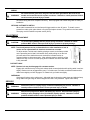
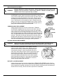
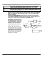
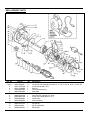
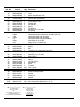
945 SERIES
SERVICE MANUAL
Daniel Woodhead Company
A Woodhead Industries, Inc. Subsidiary
IMPORTANT SAFETY INSTRUCTIONS
Please read this manual carefully and follow its instructions. Improper use or failure to follow these instructions could
result in serious injury, death or property damage. Operators should be instructed in the safe and proper use and
maintenance of this product. Keep this manual for future reference.
The following safety precautions call attention to potentially dangerous conditions.
DANGER:
Immediate hazards which WILL result in severe personal injury or death.
WARNING:
Hazards or unsafe practices which COULD result in severe personal injury or death.
CAUTION:
Hazards or unsafe practices which MAY result in minor personal injury or product or
property damage.
NOTE: Instruct operators in the safe, proper use and maintenance. Keep this manual for future reference.
INSTALLATION
WARNING:
Failure to read, understand or follow these instructions could lead to hazards or unsafe
practices COULD result in severe personal injury or death.
CAUTION:
Instruct operators in the safe, proper use and maintenance of this product. Hazards or
unsafe practices MAY result in minor personal injury or product or property damage.
NOTE: Fuse protection should be used and must not be greater than maximum reel amperage rating.
MOUNTING
Reel may be mounted on ceiling, wall, or in any position, as long as main shaft of reel is horizontal.
When possible, mount reel within two feet of an electrical outlet. For locations of more than two feet,
use a three-conductor extension cord, with wire size equal to or larger than on reel. Use mounting
bracket as a template for location of 1/4” screw holes. Template dimensions are 3-11/16” by 7/8”,
center to center.
SECONDARY SAFETY CABLE
DANGER:
A secondary safety cable or chain is to be attached to reels mounted overhead to
prevent reel from falling. Immediate hazards WILL result in severe personal injury or
death.
A 3/16 hole is provided on the base of reel to permit installation of a secondary support chain. All reels
mounted over head should have a secondary support chain to protect personnel in case of structure or
mounting component failure. Attach one end of secondary support chain or cable to secondary
support point and the other to a support component other than that which supports the reel. Chain or
cable should be as short as possible allowing reel to drop no more than 6 to 12 inches if primary
connection is released. Supports are offered as an accessory item.
SM311403B
Page 1 of 6
©AMCO Jan-03
WIRING
WARNING:
Do not disconnect green wire, the green wire has been grounded to the frame on all
models and cannot be used as a power conductor. Hazards or unsafe practices COULD
result in severe personal injury or death.
All internal wiring has been completed at factory. Reels equipped with handle and guard are ready for
installation.
OPTIONAL AUTOMATIC SWITCH
When cable is retracted into reel, ball stop will trigger switch to shut off power. To install, remove
screws from cable guide, place switch over guide and replace screws. Plug cord from reel into switch.
Then plug cord from switch into power source (Kit D).
ADJUSTMENT
TENSION ADJUSTMENT
CAUTION:
To prevent spring damage test for proper spring revolutions. Hazards or unsafe
practices MAY result in minor personal injury or product or property damage.
NOTE: Tension adjustment can be performed before or after installation of reel &
can be can be adjusted after all electrical connections are made.
To adjust tension, hold the main shaft by placing a wrench on the flats provided
on the protruding end of shaft. Hold wrench firmly while pulling out on the lock
pin knob and turn the shaft with wrench clockwise to increase tension or
counterclockwise to decrease tension. After adjusting tension, carefully pull the
cable all the way out to be sure the spring does not bottom out before the cable
is fully extended.
RATCHET LOCK
NOTE: Ratchet lock may be disengaged for constant tension.
Engage lock release lever by turning lock release knob counterclockwise while pulling cable in and out
slightly. Ratchet lock can engage about every 6” of cable travel. Pull cable to desired location and let
cable retract slightly until lock engages. To release lock, pull cable out slightly.
OVERHANG
Overhang will reduce active cable travel. Adjust ball stop by loosening cable clamp and slide ball stop
along cable until light hangs at desired length when cord is fully retracted. Tighten cable clamp.
SERVICE
WARNING:
Disconnect power or unplug supply cord before attempting any service. Hazards or
unsafe practices COULD result in severe personal injury or death.
WARNING:
Remove all spring tension before attempting any service. Secure broken spring by
welding or wire wrapping in four (4) locations (equally spaced). Hazards or unsafe
practices COULD result in severe personal injury or death.
SM311403B
Page 2 of 6
© AMCO Jan-03
MAIN SPRING REPLACEMENT
WARNING:
Spring is dangerous. Always wear gloves. Before removing broken spring, weld coils
together at four (4) locations or wrap securely with wire. Hazards or unsafe practices
COULD result in severe personal injury or death.
Unplug reel and remove ALL tension as described in TENSION
ADJUSTMENT section. Remove screw from main shaft & complete
cover. Remove shaft-retaining ring and pull tension pin down, then slide
complete drum assembly and shaft out of housing. Remove spacer
from shaft and remove shaft. Remove nuts from cover then remove
cover. Carefully remove main spring from spool. Replace new main
spring in drum. Be sure spring hook engages on lip of drum. Reverse
the above procedure to reassemble. Be sure shaft engages hook on
spring when reassembling. See Illustrations below.
WORKING CABLE REPLACEMENT
Unplug reel and remove ALL tension as described in TENSION
ADJUSTMENT section. Remove screw from main shaft & pull off
cover. Remove shaft-retaining ring and pull tension pin down, then
slide complete drum assembly and shaft out of housing. Carefully
slide slip ring assembly out of drum and disconnect wires from slip ring
ass’y. Unwind cable and then loosen drum clamp. Remove cable with
grommet. Slide cable out through cable guide from housing. When
equipped with hand lamp or fluorescent lamp, remove from cable (see
hand Lamp replacement instructions below). Replace old cable with
new cab le and reassemble by reversing the above procedure.
SLIP RING & BRUSH REPLACEMENT
WARNING:
Check reel for proper continuity, polarity and grounding before connecting power.
Hazards or unsafe practices COULD result in severe personal injury or death.
Remove tension as described in ADJUSTMENT. Remove
screw from main shaft & remove cover. Slide slip ring from
shaft and remove wiring. Rewire and replace slip ring by
reversing the procedure. Remove brush plate. Be sure to
rewire in the same order as before. Remove ground screw and
terminal from lead-in cable. Then, remove screws and brush
plate with springs and pins. Remove brushes by removing
screw and hardware with leads from lead in cable. Replace
brush assembly and lead wire in same order as disassembly.
Reverse the above procedure to reassemble. Be sure to
replace springs between plate and cover.
RATCHET LOCK REPLACEMENT
Unplug reel and remove ALL tension as described in TENSION ADJUSTMENT section. Remove
screw from main shaft & pull off cover. Remove shaft-retaining ring and pull tension pin down, then
slide complete drum assembly and shaft out of housing. Remove retaining ring and unclip spring of
ratchet lock from housing. Reverse the above procedure to reassemble.
SM311403B
Page 3 of 6
© AMCO Jan-03
HAND LAMP REPLACEMENT & INSTALLATION
WARNING:
Check reel for proper continuity, polarity and grounding before connecting power.
Hazards or unsafe practices COULD result in severe personal injury or death.
WARNING:
Disconnect power or unplug supply cord. Hazards or unsafe practices COULD result
in severe personal injury or death.
Incandescent: Remove guard and bulb. Remove screws from sides of handle. Remove cable stop
assembly, bumper, spring, ball, and cable wiring. Strip wire as needed and wire cable to replacement
handle: black to brass screw, white to silver screw, and green to green screw. Reverse the above
procedure to reassemble.
Power Cord or Transform Assembly: Remove bolt to open reel cover. Remove the wires that
connect the power cord/transformer assembly wires to the brush plate. Attach the lugs on the new
cord/transformer assembly wires to the brush assembly. Reassemble the reel.
13W Florescent: Disassemble new hand
lamp. Strip the black and white wires from
the cord and tin ends. Cut and remove the
green wire as close to the outer jacket as
possible. Press replacement lamp into
connector until firmly retained. Push
stripped and tinned wire leads into quickconnect wiring holes in bottom of
connector. Slide replacement lamp into
protective tube so that the end of the lamp
is seated in the end of the tube. Slide tube
and lamp assembly into the handle while
pulling cord until tube and lamp are seated.
Secure tube with screws in sides of handle.
Replace nut, plastic washer, and rubber
strain relief onto lamp handle.
SM311403B
Page 4 of 6
© AMCO Jan-03
REPLACEMENT PARTS
Ref. No.
1
2 (Kit C)
3
4
5
6
7
8
9
10
11
12
13
14
15
SM311403B
Part No.
AM00580P0050
AMH22520007
AM01137P0060
AM3127400000
AM0208500000
AM0207400000
AM0208000346
AM00701P0010
AM00002P0202
AM0004800000
AM0330600000
AM00103P0020
AM00151P0015
AMH96310001
AMM84780004
Qty.
1
1**
6
1
1
1
1*
1
2
1
1
1
1
1
1
Description
Retaining ring (.500 shaft)
Housing & lock Assembly (included: 3, 27, 28, 37, 38, 39, 40, 41, 42, 48, 49)
Screw self-tap (#8 x 3/8”)
Bushing
Cover plate assembly
Main shaft
Main spring
Grommet (3/8” cable @ 1/2” hole)
Screw round head (#6-32 x 1/2”)
Cable clamp
Drum assembly
Lock washer
Nut (#6-32)
Slip ring assembly
Brush plate
Page 5 of 6
© AMCO Jan-03
Ref. No.
16
17
18
19
Part No.
Qty.
AM00103P0035 3
AM00002P0901 3
AM0303400000 1
AM00916P0003 1
AM6234600003
20
1
Contact Factory
21
AM0207100000 1
22
AM00002P0101 5
23
AM00103P0035 6
24
AM00151P0085 5
25
AM00600P0010 2
26
AMM82310002
2
27
AM00580P0030 1
28
AM0967400000 1
1083HONS
1086-3
106S
1
30
106US
118
3000-1
1547
31
AM0009500000 1
32
AM0202500001 1
33
AM0202400001 1
34
AM0004700001 1
35
AM00047P0001 3
36
AMM10720062
1 *
37
AM0333900000 1
38
AM00580P0020 1
39
AM0207800000 1
40
AM0207600000 1
41
AM0207500000 1
42
AM0207700000 1
43
AM00152P0006 3
44
AM5786700000 3
45
AM00041P0050 2
46
AM01149P0050 A/R
47 (Kit D) AM01026P0012 A/R
48
AM0200600000 1
49
AM02009000YE 1
50
AMC01010222
1
51
AM00228P0010 1
52
AM0981300000 1
53
AM3123400000 1
Kit A
AMH92110001
A/R
Kit B
AMH92110002
A/R
* - Recommended spare parts,
Daniel Woodhead Company
W
A Woodhead Industries Inc. Subsidiary
3411 Woodhead Drive
Northbrook, IL 60062
USA
888-996-6343 Fax: (847) 272-8133
www.danielwoodhead.com
[email protected]
SM311403B
Description
Lock washer int. Th. (#8)
Screw - brass (#8-32 x 7/16”)
Cover
Strain relief (.625 DIA. Hole)
Lead-in cable without transformer
Lead-in cable (945-3SWFL)
Screw, main shaft
Screw (#8-32 x 5/16”)
Washer (#8)
Nut (#8-32)
Spring
Pin aligning
Retaining ring (.375 shaft)
Kit; Spring
Hand lamp Florescent (945-3SWFL)
Hand lamp Florescent transformer in handle (945-3-86)
Hand lamp handle and guard (962)
Hand lamp handle and guard (963)
Hand lamp handle and guard (964SW)
Dual Outlet Box 5-15 (966)
Single Outlet 5-15 (945-1547)
Cable stop assembly
Bumper
Spring
Ball
Terminal (If with incandescent hand lamp)
Working cable
Cable guide
Retaining ring (.187 shaft)
Knob, lock pin
Bushing, lock pin
Spring
Lock pin, tension
Nut (#8-32)
Brush
Terminal
Wire – green
Automatic switch - optional
Pin
Swivel mounting bracket
Washer
Cotter Pin
Washer
Washer
Brush plate assembly (inc. 15, 16, 17, 43, 44)
Slip ring and cable assembly (inc. 14, 36)
Woodhead Canada LTD.
W
A Woodhead Industries Inc. Subsidiary
1090 Brevik Place
Mississauga Ontario
L4W 3Y5 Canada
(905) 624-1079
FAX: (905) 624-9151
www.woodhead.ca
Page 6 of 6
© AMCO Jan-03