1
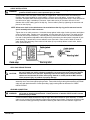
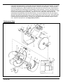
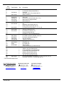
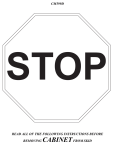
Ground Fault Cable Retractor GR1000L
Service Manual
AERO-MOTIVE COMPANY
A Woodhead Industries, Inc. Subsidiary
IMPORTANT SAFETY INSTRUCTIONS
Please read this manual carefully and follow its instructions. Improper use or failure to follow these instructions could
result in serious injury, death or property damage. Operators should be instructed in the safe and proper use and
maintenance of this product. Keep this manual for future reference.
The following safety precautions call attention to potentially dangerous conditions.
DANGER:
Immediate hazards which WILL result in severe personal injury or death.
WARNING:
Hazards or unsafe practices which COULD result in severe personal injury or death.
CAUTION:
Hazards or unsafe practices which MAY result in minor personal injury or product or
property damage.
NOTE: Instruct operators in the safe, proper use and maintenance. Keep this manual for future reference.
Model GR1000 reel retracts up to 50 feet #4/0, or 60 feet of #2/0 AWG grounding cable used to protect equipment and
personnel in the event of a ground fault. The collector ring electrical path through the reel is designed with a current
carrying capacity greater then that of the largest cable (#4/0 AWG) to be installed on the reel.
WARNING:
Failure to lock spool assembly in position with cable fully extended as instructed will create
an explosion hazard. In the event of a fault condition, hazards or unsafe practices COULD
result in severe personal injury or death.
WARNING:
The internal electrical path is not insulated from the reel frame therefore this reel is
unsuitable for uses other than retracting ground cables. Use for other applications will
create an electric shock hazard. Hazards or unsafe practices COULD result in severe
personal injury or death.
WARNING:
Failure to install, operate, and maintain retractor in accordance instructions may result in
electrical shock. Hazards or unsafe practices COULD result in severe personal injury or
death.
WARNING:
If a ground fault has occurred, return reel to Aero-Motive Company for inspection and
possible repair before placing back in service. Failure to do so could result in an electric
shock hazard. Hazards or unsafe practices COULD result in severe personal injury or death.
INSTALLATION
REEL MOUNTING
Reel may be mounted with the base up, base down, or in any position, that maintains the main shaft in a
horizontal position. Reel should be mounted with spool assembly in line with the direction of cable travel.
CAUTION:
Misalignment of reel and cable travel direction will cause cable to be deflected at a sharp angle
around cable guide rollers. This may shorten life of cable and/or slow retraction rate. Hazards
or unsafe practices MAY result in minor personal injury or product or property damage.
CAUTION:
Reel should be bolted securely to a flat metal surface of sufficient strength and rigidity to
support it under all conditions to which it will be subjected. Mounting holes will accommodate
1/2 inch or 12mm bolts. Hazards or unsafe practices MAY result in minor personal injury or
product or property damage.
SM3180-08E
Page 1 of 5
©Aero-Motive Company Dec-03
CABLE INSTALLATION
WARNING:
All steps related to termination of the cable must be followed carefully. Hazards or unsafe
practices COULD result in severe personal injury or death.
Select suitable cable size (#4/0 or #2/0 AWG) to fit application. Cable should have fine stranding for
flexibility and a jacket suitable for rough handling. Remove cover and gasket. Loosen nut on cable
connector, and pass cable end through the cable connector then through cable clamp. Either strip and tin
the cable end or apply a suitable pin connector. Insert cable end or pin connector into the .65 inch
diameter hole on the rotating part of the slip ring. Secure cable in place by tightening the set screw and
jam nut on the slip ring.
NOTE: Allow some slack in the cable between its termination at the slip ring and its entrance into the
spool assembly at the cable connector.
Tighten the nut on cable connector. Hold cable clamp against inside edge of cable connector and tighten
screw to secure cable. Replace cover and gasket, securing them with six lock nuts. The cable can now
be wound onto the spool assembly. A warning label is provided with retractor and must be attached to
free end of cable between adjustable cable stop and the point where the cable jacket is stripped off (see
parts drawing). To attach label, remove adhesive cover from back. Place center of label on center of
cable. Wrap cable both ways from center so both sides (if any remains) adhere to each other, back to
back. (See illustration.)
If cable is replaced at a later date, contact Aero-Motive Co. at 1-800-999-8559 for replacement label.
APPLYING SPRING TENSION
CAUTION:
Check to make sure that the cable can still be pulled out without winding the main spring to
the end. If cable can not be pulled out completely, too many prime turns have been applied
and some will have to be removed. Operating reel with too many prime turns will restrict
cable travel and shorten life of the main spring. Hazards or unsafe practices MAY result in
minor personal injury or product or property damage.
After cable is fully wound on spool assembly, develop one and two prime tension turns by rotating spool
assembly one or two times against spring tension. Pass cable through cable guide assembly and install
cable stop with desired amount of cable protruding. Apply warning label as discussed in “CABLE
INSTALLATION”.
GROUND CONNECTION
WARNING:
Failure to make a mechanically and electrically sound connection at both ends of this cable
will create an electrical shock hazard. Unsafe practices or hazards COULD result in severe
personal injury or death.
Ground connection cable should be as large or larger than cable installed on spool assembly. To attach
cable to reel, connect 5/8 inch diameter copper rod protruding beyond base. Connection should be made
with a commercial fitting specifically intended for attaching this cable to 5/8 inch diameter copper rod.
SM3180-08E
Page 2 of 5
©Aero-Motive Dec-03
CABLE GUIDE
CAUTION:
Pulling cable at sharp angles to cable guide will shorten cable life and retard retraction speed.
Hazards or unsafe practices MAY result in minor personal injury or product or property
damage.
To position guide assembly, remove two screw and washers. Place guide assembly so that cable will
wrap directly onto assembly with as little deflection over roller as possible. Cable guide assembly can
now be positioned in any one of for locations. Insert and tighten the two screws and washers through
base into guide assembly.
OPERATION
RATCHET LOCK
Model GR1000 is equipped with a ratchet, which will hold spool assembly at any of several positions per
spool assembly revolution and prevent it from retracting. To release the ratchet, pull the cable out until
the ratchet assembly disengages. Reel can then retract cable.
GROUND FAULT CONNECTION
WARNING:
Failure to unwind full length of cable and to padlock spool to prevent its inadvertent
rewinding, in the event of a ground fault, will create an explosion hazard. Hazards or unsafe
practices COULD result in severe personal injury or death.
WARNING:
Personnel should be kept at a safe distance from Ground Fault reel and cable. In the event of
a ground fault, the sudden surge of power will cause cable to move violently. Hazards or
unsafe practices COULD result in severe personal injury or death.
WARNING:
This reel is intended for use in grounding circuit only. The electrical path is not insulated
from the reel frame. Hazards or unsafe practices COULD result in severe personal injury or
death.
WARNING:
Check all electrical connections on retractor and ground cable terminations before use.
Failure to do so may result in shock hazard. Hazards or unsafe practices COULD result in
severe personal injury or death.
When cable is pulled out and connected to provide ground fault protection, all cable should be fully
extended to provide maximum current capacity. A padlock must be installed on reel trough the hole
provided in flange of spool. This padlock prevents spool assembly rotation and assures that the cable
remains unwound should a ground fault occur.
MAINTENANCE AND SERVICE
WARNING:
If a ground fault condition has occurred, remove reel from service immediately and return it
to Aero-Motive Company for inspection and, if necessary, repair. Failure to do so could
result in an electric shock hazard. Hazards or unsafe practices COULD result in severe
personal injury or death.
ELECTRICAL
Inspect all cable connections monthly. Resistance through reel slip ring assembly should never exceed
0.001 ohms. If so, return to Aero-Motive Company for inspection and repair.
NOTE: The slip ring assembly has been designed in such a manner that it cannot be disassembled.
MAIN SPRING REPLACEMENT
WARNING:
Spring pocket assemblies are sealed to prevent disassembly. Do not attempt to remove
spring from its pocket. Hazards or unsafe practices COULD result in severe personal injury
or death.
WARNING:
Carefully inspect all wire connections after any service work is conducted. Hazards or
unsafe practices COULD result in severe personal injury or death.
SM3180-08E
Page 3 of 5
©Aero-Motive Dec-03
If reel will not develop tension or retract cable, the spring assembly may need to be replaced. To replace
mainspring, disconnect the input grounding connection. Remove cover and gasket. Loosen setscrew,
and remove retaining ring. Slide complete spool with main shaft out of hub in the base. Remove the six
lock nuts that fasten the mainspring housing assembly to spool assembly. Remove mainspring housing
assembly, being careful not to misplace the key. Remove hub from mainspring housing assembly. Install
hub into new mainspring housing assembly. Insert key into slot in main shaft. Slide hub and new
mainspring housing assembly onto main shaft and key. Line up the timing hole near the outer edge of
spring housing assembly and timing hole in the spool flange. Secure with six lock nuts. Insert main shaft
into hub in the base and reassemble retaining ring to the protruding end of main shaft. Check that there
is little axial play and tighten setscrew. Secure cover and gasket to spool assembly using the six lock
nuts. Adjust the spring tension. (See Apply Spring Tension.)
Replacement Parts
SM3180-08E
Page 4 of 5
©Aero-Motive Dec-03
Item
Part Number
Number
1
2
3
C01590218
4
5
H92110023
6
H22110412
7
M34060019
8
C22490119
9 *
H41210021
10
6187000000
11
4011900000
12
4077300020
13
14
15
H18110023
16
5385600000
17
M67620008
18
H18110024
19
20
21
22
H80130008
23
H42320037
24
H96610003
25
6187300000
26
H82630046
27
00576P0020
28
STM2
29
M13630009
30
31
32
33
34
35
36
37
38
H92110026
39
* Recommended Spare Parts
Daniel Woodhead Company
A Woodhead Industries Inc. Subsidiary
Northbrook, IL USA
888-996-6343 Fax: (847) 272-8133
www.danielwoodhead.com
[email protected]
SM3180-08E
Qty.
2
2
1
1
1
1
1
12
1
1
2
1
1
1
1
1
4
2
1
1
1
1
1
1
1
1
2
1
1
1
1
1
1
1
1
1
1
1
1
Description
Cheese HD screw, M5 x 25 (included with 6)
Lock washer, M8 (Included with 6)
Grommet
Set screw, M12 x 25 (included with 5)
Base (includes 4)
Kit, Guide assembly (includes 1, 2)
Main shaft
Hex lock nut, M5 (included with 18, 23)
Main spring housing assembly
Main spring hub
Main spring spacer
Key
Retaining ring (included with 15)
Ratchet spacer (included with 15)
Kit, Ratchet pawl (includes 13, 14, 16, 39)
Spring (included with 15)
Spacer (included with 18)
Kit, Ratchet (includes 8, 17)
Clamp (included with 22)
Conduit nut 1 inch (included with 22)
Gasket (included with 22)
Kit, Cable connector (includes 19,20,21)
Kit, Spool assembly(includes 8)
Slip ring assembly
Gasket (included with 26)
Slip ring cover
Retaining ring
Kit, Cable stop
Warning label
Screw, M10x20mm (included with 38)
Lock washer, M10 (included with 38)
Washer, M10 (included with 38)
Screw, M6x20mm (included with 38)
Lock washer, M6 (included with 38)
Washer, M6 (included with 38)
Bolt M12x40 (included with 38)
Jam nut, M12 (included with 38)
Kit, Slip Ring Bracket (includes 30, 31, 32, 33, 34, 35, 36, 37)
Clevis pin, 3/16 DIA. x 1/2 (included with 15)
Woodhead Canada LTD.
A Woodhead Industries Inc. Subsidiary
Mississauga Ontario Canada
(905) 624-1079 FAX: (905) 6249151
www.woodhead.ca
Page 5 of 5
Aero-Motive Company
A Woodhead Industries Inc. Subsidiary
Kalamazoo, MI USA
(269) 337-7700 FAX: (800) 333 6119
www.aeromotive.com
[email protected]
©Aero-Motive Dec-03