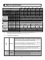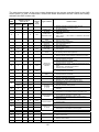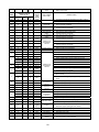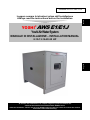
1
Leggere sempre le istruzioni prima dell'installazione Always read the instructions before the installation YOSHI® AWS E1/E1J Italiano AWSMAN–E1/E1J–1205 IT EN Yoshi Air Water System MANUALE DI INSTALLAZIONE – INSTALLATION MANUAL English 8-10-13-16-20-25 HP Al termine dell’installazione, far sempre eseguire il primo avviamento dal Centro di Assistenza Tecnica Autorizzato AISIN di zona. After the installation, always call the local AISIN Authorised Service Centre to perform the outdoor and indoor units commissioning. DICHIARAZIONE CE DI CONFORMITA’ CE DECLARATION OF CONFORMITY Dati identificativi del fabbricante: Identification of the manufacturer: Tecnocasa s.r.l. Sede legale: Via Manzoni, 17 60025 Loreto (AN) Italia Dichiara che l’insieme per la macchina YOSHI AWS (Air Water System) Declare that the assembly for the YOSHI AWS (Air Water System) unit: Modelli: Models: AWS08HP E1/E1J AWS10HP E1/E1J AWS13HP E1/E1J AWS16HP E1/E1J AWS20HP E1/E1J AWS25HP E1/E1J Matricola: vedi targa dati Serial n°: see product label Anno di costruzione: vedi targa Year of construction: see product label È conforme ai requisiti essenziali di sicurezza delle seguenti direttive: Is compliant to the essential safety requirement of the following directives: 9 DIRETTIVA PED 97/23/CE e successive modifiche – Cat. Rischio I° – (PED DIRECTIVE 97/23/CE and subsequent modification – Cat. Risk I°–) 9 DIRETTIVA MACCHINE 2006/42/CE e successive modifiche (MACCHINE DIRECTIVE 2006/42/CE and subsequent modification) 9 DIRETTIVA BASSA TENSIONE LVD 2006/95/CE e successive modifiche ( LOW TENSION DIRECTIVE LVD 2006/95/CE and subséquent modification) 9 DIRETTIVA COMPATIBILITA’ ELETTROMAGNETICA EMC 2004/108/CE e successive modifiche (ELECTROMAGNETIC COMPATIBILITY DIRECTIVE EMC 2004/108/CE and subsequent modification) Loreto, 1° Gennaio 2012 Deutsch Rappresentante Legale (the Legal Representative) YOSHI® AWS E1/E1J Yoshi Air Water System AWS INSTALLATION MANUAL 8 HP-10 HP-13 HP-16 HP-20 HP-25 HP Models Capacity (kW) AWS E1/E1J Series COOLING HEATING (Maximum) 8 HP 21,0 23,5 10 HP 26,5 30,0 13 HP 33,5 37,5 16 HP 41,0 47,5 20 HP 52,0 60,0 25 HP 63,5 75,0 Safety prescriptions The following symbols are used to indicate important instructions. Always read, understand and follow these instructions carefully. Failure to observe the prescriptions indicated with this symbol could result in WARNING serious injury or death. CAUTION Failure to observe the prescriptions indicated with this symbol could result in damage to the unit. This symbol indicates a forbidden action. This symbol indicates a necessary action. Notice for the installer WARNING This unit has to be installed by specialised technical personnel. The installation must be performed in accordance with the contents of this manual. If this unit is not properly installed, it will not realize its full performance potential and could cause injury or damage. This manual contains technical prescriptions, precautions and procedures to installa the YOSHI AWS unit properly. It addresses to specialised technical personnel with a basic knowledge of gas heat pumps installation methods. Failure to observe the procedures herein indicated, could result in malfunction and damage to the unit. Before beginning the installation of the YOSHI AWS unit, read and fully under stand the contents of this manual. After the installation, always call the local AISIN Authorised Service Centre to perform the outdoor and indoor units commissioning. Tecnocasa s.r.l. declines any responsibility for any damage whatever caused by improper use of the unit and/or non compliance with the information contained in this manual. Specifications, drawings and technical information in this manual are subject to change without notice. 31 32 INDEX Technical features 1 AWS unit specifications........................................................................................................... 34 1.1 Installation prescriptions.................................................................................................. 34 2 Before installation.................................................................................................................... 35 2.1 Parts provided ................................................................................................................. 35 2.2 Locally procured parts ..................................................................................................... 35 3 Using a mixture of water and glycol ........................................................................................ 36 AWS unit installation 4 Installation ............................................................................................................................... 36 4.1 Selecting the location for installation ............................................................................... 36 4.2 External dimensions, hydraulic and refrigerant gas connections .................................... 37 4.3 Installation space............................................................................................................. 38 5 Refrigerant pipes..................................................................................................................... 39 5.1 Outline drawing of refrigerant piping. .............................................................................. 39 5.2 Piping specifications........................................................................................................ 40 5.3 Refrigerant gas extra charge........................................................................................... 41 6 Refrigerant circuit and hydraulic circuit ................................................................................... 42 6.1 Cooling mode .................................................................................................................. 42 6.2 Heating mode .................................................................................................................. 42 AWS unit wiring Electric wire installation........................................................................................................... 43 7.1 Wiring with GHP outdoor unit for AWS............................................................................ 43 7.2 Detailed wiring diagram................................................................................................... 44 8 Accessories AWS.................................................................................................................... 43 8.1 Controller Plus: control panel and probe temperature buffer tank................................... 44 8.1.1 Control panel ................................................................................................................... 44 8.1.2 Probe temperature buffer tank ........................................................................................ 44 8.2 External probe temperature............................................................................................. 44 Control panel........................................................................................................................... 46 9 10 Adjustment AWS set point ...................................................................................................... 47 10.1 Control panel ................................................................................................................... 49 10.2 Setting the offset ............................................................................................................. 49 11 Installation layouts................................................................................................................... 49 11.1 Central storage tank installation ...................................................................................... 49 11.2 Hydraulic separator installation ....................................................................................... 49 11.3 Single pump installation .................................................................................................. 49 11.4 HVAC installation layout AWS E1 (internal pump) .......................................................... 50 11.5 HVAC installation with proportional distribution of consumption ..................................... 51 11.6 HVAC installation with pump external variable flow rate ................................................. 52 11.7 HVAC installation a variable flow rate ............................................................................. 53 12 Trouble diagnosis (reference) ................................................................................................. 54 33 Deutsch 7 1 AWS unit specifications All versions Capacity code of the connected GHP outdoor unit kW Rated cooling capacity∗ Water temperature out - [in] °C kW Rated heating capacity ∗∗ Water temperature out - [in] °C Flow rate m3/h Capacity modulation rate cooling (min-max) kW Capacity modulation rate heating (min-max) kW V/Ph/Hz Power supply∗∗∗ Power consumption kW 19.8-75.0 Starting current A Available static pressure kPa Version without Power supply V/Ph/Hz Pump (AWS E1J) Starting current A Drop pressure plate heat exchanger kPa Water pipes connection Inch Water circuit Primary circuit pipes diameter Refrigerant gas connection (gas – liquid) Refrigerant circuit GHP – AWS pipes diameter (gas – liquid) Height External Width dimensions and Depth weight With Pump/Without Pump Connectable GHP outdoor units ∗ ∗∗ ∗∗∗ ∗∗∗∗ 1.1 Inch AWS 8HP-E1 (E1J) P224 21,0 7 – [11] 23,5 45,5 – [41] 4,5 10,0-21,0 13,0-23,5 mm mm mm kg AWS AWS 13HP-E1 16HP-E1 (E1J) (E1J) P355 P450 33,5 41,0 7 – [12] 7 – [12] 37,5 47,5 45,5 – [40] 45,5 – [40] 6,0 7,5 10,0-33,5 17,0-41,0 12,0-37,5 19,8-47,5 230/1/50 AWS 20HP-E1 (E1J) P560 52,0 7 – [12] 60,0 45,5 – [40] 9,5 17,0-52,0 19,8-60,0 0,84 AWS 25HP-E1 (E1J) P710 63,5 7 – [12] 75,0 45,5 – [40] 12,0 17,0-63,5 19,8-75,0 1,1 10 80 80 60 100 80 60 230/1/50 1,5 33 33 22 33 46 2 (Each AWS unit is delivered with 2” nipless fittings to be installed if necessary) 2 or higher (Each AWS unit is fitted with a 2” Y-shape filter to be installed on the primary circuit) mm mm AWS 10HP-E1 (E1J) P280 26,5 7 – [12] 30,0 45,5 – [40] 4,5 10,0-26,5 12,0-30,0 46 28,6 –12,7 19,1 – 9,5 (12,7) ∗∗∗∗ 22,2 – 9,5 (12,7) ∗∗∗∗ 28,6 – 18,0 25,4 – 12,7 ∗∗∗∗ (15,9) 28,6 – 12,7 ∗∗∗∗ (15,9) 28,6 – 15,88 ∗∗∗∗ (19,05) 35 – 15,88 (19,05) ∗∗∗∗ 915 1020 710 164/153 204/177 Each AWS unit can be connected with a single AISIN GHP outdoor unit Rated cooling capacity is measured according to the following conditions: water outlet temperature 7°C; outdoor temperature 35°C DB Rated heating capacity is measured according to the following conditions: water outlet temperature 47°C; outdoor temperature 7°C DB / 6°C WB A version fitted with 230V, single phase, 60 Hz is available upon order. If the distance between GHP and AWS exceeds 40 meters, install a pipe with the diameter indicated in brackets. Installation prescriptions Always foresee the installation of an emergency relief valve and a properly dimensioned expansion vessel. These devices are not built in the AWS unit. Where the storage tank should be installed lower than the AWS unit, foresee the installation of a jolly valve at the higher point of the water piping. Failure to observe these prescriptions could result in malfunction and/or damage to the unit. CAUTION Always foresee the installation of a buffer tank, fitted with anti stratification pipes, which size should be adequate to the AWS unit capacity. Failure to observe these prescription could result in malfunction and/or damage to the unit. Always check that the Y-shape water filter (supplied with the unit) is installed on the primary circuit return pipe. In case of multi units plants, install one filter each AWS unit. Install the filter to not less than 50 cm from suction of the pump. Failure to observe this prescription makes the warranty no longer valid and could result in malfunction and/or damage to the unit. WARNING Welding, refrigerant gas and water piping installation should be always performed by specialised technical personnel in accordance with instructions and prescriptions mentioned in the present manual. Failure to observe this prescription makes the warranty no longer valid and could result in malfunction and/or damage to the YOSHI AWS unit. 34 2 Before installation 2.1 Parts provided The following parts are provided with the YOSHI AWS unit. Name 2” Y-shape filter For water pipe [gaskets] 1 - [2] Installation Control box manual wiring diagram 1 1 Inside the control panel Always store the manuals in a dry and safe place Quantity Location Note 2” brass nipless [gaskets] 2 - [2] Inside the unit near the water connections Refer to the prescriptions of this manual for the installation of the accessories 2.2 Locally procured parts The following items are required for installing the YOSHI AWS unit. Part Application Anchor bolt For installing the AWS unit on the ground (M8X4) Washer, Nuts For installing the AWS unit on the ground (φ8X4) Ant vibrant carpet For installing the unit on metal bars or on the roof. Copper pipe and fittings for refrigerant gas Steel pipe and fittings for water Refrigerant gas piping Insulation For refrigerant gas and water pipe insulation Electrical wires AWS unit power supply, ground wiring, communication and accessories wiring R410a refrigerant gas, precision scale and gauge manifolds Refrigerant circuit extra charge Oxy acetylene welding kit Gas bottles, nozzle and copper bars to weld refrigerant pipes Nitrogen Bottle Vacuum pump Pipe cutter (materials and procedures are described in the GHP outdoor unit installation manual) Water piping (materials and procedures are described in the present manual) (proper size and wire specifications are described in the GHP outdoor unit installation manual) (refrigerant extra charge is described in the present manual) Refrigerant gas leakage test (the procedure is described in the GHP outdoor unit installation manual) Vacuum suction (the procedure is described in the GHP outdoor unit installation manual) Refrigerant gas piping installation WARNING Never use parts which are not compliant with those listed in the present manual. Failure to observe this prescription makes the warranty no longer valid and could result in malfunction and/or damage to the unit. The installation of the unit must comply with national and local codes. Failure to observe this prescription could result in illegal act. The manufacturer specifically disclaims any liability whatsoever for any claims by any party if any of the procedures in this Installation Manual have not been followed. Failure to observe this prescription makes the warranty no longer valid. 35 3 Using a mixture of water and glycol Use mixtures of water and antifreeze fluid to lower the freezing point of water. The liquid most commonly used as antifreeze is ethylene glycol. The table shows the reduction factors of the cooling capacity and the capacity of the pump of the AWS as a function of the water temperature and percentage by weight of glycol in the mixture. Water Glycol °C -2 -4 -6 -9 -12 -15 -19 -23 -29 -35 % kg 5 10 15 20 25 30 35 40 45 50 Reduction factor of the cooling capacity 0,995 0,990 0,985 0,980 0,975 0,970 0,965 0,960 0,955 0,950 Reduction factor of the pump flowrate 0,99 0,98 0,96 0,94 0,92 0,90 0,88 0,86 0,83 0,80 4 Installation 4.1 Selecting the location for installation WARNING • The unit MUST NOT be installed where flammable gas is generated, accumulated or handled. Failure to observe this prescription could result in damage of the unit, injury, fire or explosion. • The AWS unit is for outdoor and indoor installation. Read the present manual carefully to select a proper installation location. Make sure maintenance space is provided around the unit. If the unit is installed at high location, provide a safe access by installing ladders or railings for the operator. • • Always install the AWS unit in an area where its smooth operating noise and small vibration won’t be a disturb for the neighbours, particularly in residential areas. Comply to local standards where prescribed. • Always install the AWS unit in a level location where rainwater cannot accumulate. Provide proper drain routes. • Always install the AWS unit in a location where it won’t be exposed to strong winds. Provide proper anchor bolts. • The AWS unit might cause slight interference with other electrical equipment, such as televisions, radios, computers and telephones. Provide proper clearances. • If the AWS unit is installed in a region with heavy snowfall, install a snow protection hood. The base for the unit is high enough to avoid accumulation of snow in front of the body panels. • Allocate the route for loading/unloading the unit, materials and parts for maintenance at the installation site. 36 4.2 External dimensions, hydraulic and refrigerant gas connections The table below shows the diameters of the water connections, refrigerant, piping diameters and their position in the various models of AWS. TECHNICAL DATA Water connections Inch φ2 Water pipe connections Inch φ 2 or higher Refrigerant gas connections mm Refrigerant pipes diameter mm Hydraulic and refrigerant gas connection positions (8 – 10 – 13) HP Liquid Gas Water mm Dimensions (W -H - D) Liquid 12,7 8 HP Liq. Gas 9,5 19,1 (16-20-25) HP 10 HP Liq. Gas 9,5 22,2 (8-10-13) HP (16-20-25) HP (16 – 20 – 25) HP Gas 28,6 13 HP Liq. Gas 12,7 25,4 Liquid 18,0 16 HP Liq. Gas 15,9 28,6 Liq. 15,9 20 HP Gas 28,6 Gas 28,6 25 HP Liq. Gas 15,9 35,0 (8-10-13) HP (8-10-13-16-20-25) HP A B C D E 130 210 290 375 525 mm 710 -915 - 1020 37 4.3 Installation space Clearances for maintenance and inspection operations are described in the tables below. CAUTION • • The minimum installation spaces are necessary to provide room for air circulation, inspection and maintenance of the AWS unit. Failure to observe this prescription could result in injury to the maintenance personnel and damage to the unit. When more units are installed in the same location, make sure that nearby walls, pipes or other objects, are not obstructions for maintenance operations. Maintenance space is described in the table below. Always provide ample space for inspecting and maintaining the piping for the refrigerant gas and for the water. Front view Top view <Single unit installation > Always leave at least 500 mm on the right side (viewed from coupling tubes AWS) Always provide 1 m or more above the AWS unit <Overlapped multiple units installation> <Multiple units installation> When the units are overlapped, route the pipes of the upper unit so that all the body panels of the lower unit can be disassembled. Always leave at least 500 mm on the right side (viewed from coupling tubes AWS) 38 5 Refrigerant pipes 5.1 Outline drawing of refrigerant piping. WARNING All the welding operations on the AWS – GHP refrigerant gas piping must be always performed in accordance with instructions and prescriptions mentioned in the AISIN GHP installation manual (brazing with nitrogen flow). Failure to observe this prescription makes the warranty no longer valid and could result in malfunction and/or damage to the YOSHI AWS unit. 39 5.2 Piping specifications WARNING YOSHI AWS refrigerant gas connections diameter differs from the ones prescribed for the refrigerant gas line to the AISIN GHP outdoor unit. Therefore, install proper adapters (not supplied). Select the proper AWS – GHP pipe diameter according to the table below. Installation item YOSHI AWS AISIN GHP Unit GHP Multi Type AWS E1/E1J Acceptable piping Diameter x Thickness (mm) length (m) [8 HP] [10 HP] [13 HP] [16 HP] [20 HP] [25 HP] Gas Liquid Liquid (*) 19,1x1,0 22,2x1,0 25,4x1,0 28,6x1,5 28,6x1,5 35,0x1,5 9,5x1,0 9,5x 1,0 12,7x1,0 15,9x1,0 15,9x1,0 15,9x1,0 12,7x1,0 12,7x1,0 15,9x1,0 19,05x1,0 19,05x1,0 19,05x1,0 (relative/actual) 70/60 Max. height difference(m) GHP ground GHP roof Compressor oil 20 25 NL10 (*) If the distance between GHP and AWS exceeds 40 meters use a liquid tube of bigger diameter as indicated in the table. The refrigerant gas line for the YOSHI AWS unit must be designed and installed in accordance with the prescriptions here under listed. Layout example (in case of AWS connection) If there is a height difference between the locations of indoor and outdoor units, be sure to apply “trap piping” on the vapour line within every 10 m as illustrated. Piping length Maximum piping length (L) Height difference Height difference between indoor unit and outdoor unit (H) L=A (Relative/Actual) When GHP outdoor unit is higher than AWS unit When GHP outdoor unit is lower than AWS unit 70/60m or less 25 m or less 20 m or less CAUTION It is forbidden to connect direct expansion indoor units and YOSHI AWS to a single AISIN GHP outdoor unit simultaneously. The YOSHI AWS can be only connected to a specific AISIN GHP outdoor unit for AWS with the same capacity. WARNING • Never exceed the maximum accepted distances when connecting the YOSHI AWS to the AISIN GHP outdoor unit. Failure to observe this prescription makes the warranty no longer valid and could result in malfunctioning of the YOSHI AWS unit. 40 5.3 Refrigerant gas extra charge CAUTION The refrigerant extra charge must be done in accordance with the procedures described in the AISIN GHP installation manual. Failure to observe this prescription makes the warranty no longer no longer valid and could result in malfunctioning of the YOSHI AWS unit. WARNING Accurately measure the length of the piping and charge with the proper amount of refrigerant gas. Failure to observe this prescription could result in malfunctioning of the YOSHI AWS unit. When charging the refrigerant gas, make sure to wear proper protective gloves. Refrigerant gas leakages can cause frost bites. • Always charge the refrigerant as a liquid in the tank. In case of charging as a gas may cause a compositional change of the refrigerant, and could result in a performance decline or a breakdown. • Always use a refrigerant scale when charging the refrigerant. Using a charging cylinder may cause a compositional change of the refrigerant, could result in a performance decline or a breakdown. • To avoid cross-contamination with other oil types, make sure to separate maintenance tools according to the type of refrigerant used. In particular, never use the gauge manifold and charging hose with other refrigerants than R410a. After confirming the factory charge on the AISIN GHP label, use the following equation to determine the necessary extra amount of refrigerant gas. Always refer to the liquid pipe lengths and diameters only. Extra charge (kg) = QAWS + ( L1 × 0.170) + (L2 × 0.110) + ( L3 × 0.054) L1: Liquid pipe Ø 15.9 total length (m) L2: Liquid pipe Ø 12.7 total length (m) L3: Liquid pipe Ø 9.52 total length (m) The value of the variable parameter Q depends on the capacity of the AISIN GHP outdoor unit connected to the YOSHI AWS. Use the table below as reference. Outdoor unit Installation type Q (kg) 8 – 10 – 13 HP QAWS 0 16 – 20 – 25 HP QAWS + 1,5 41 6 Refrigerant circuit and hydraulic circuit 6.1 Cooling mode The refrigerant (R410A) processed by the GHP flows through electronic expansion valve and enters the lower part of the AWS unit heat exchanger at low pressure. The gas evaporates in the plate heat exchanger by taking heat from the counter current water flow. It goes back to the GHP as overheated steam. The outdoor unit fans create an air flow through the heat exchanger and thus the refrigerant can condense. At the same time, the water coming from the buffer tank is cooled and pumped again into the primary circuit by the AWS built in pump. Flow switch, pressure switch and anti freeze thermo sensor overlook the water temperature never to drop inside the heat exchanger. In fact, water may freeze and the heat exchanger can be damaged. 6.2 Heating mode The refrigerant (R410A) processed by the GHP enters the upper part of the AWS unit heat exchanger as high pressure overheated steam. The gas condenses in the plate heat exchanger by ceasing heat to the co current water flow. It goes back to the GHP as high pressure liquid, through the bypass pipe. The two outdoor unit expansion valves divide the return flow, reducing its pressure. The GHP manages the evaporation through the heat exchanger and the heat recovery. At the same time, the water coming from the buffer tank is heated and pumped again into the primary circuit by the AWS built in pump. 1) 2) 3) 4) 5) 6) 7) Water pressure difference switch 8) Air vent valve 9) Flow switch 10) Pump (not included in the version E1J) 11) Pressure switch expansion valve Driver expansion valve Check valve Electronic expansion valve Water inlet temperature probe Water outlet temperature probe Plate heat exchanger 42 7 Electric wire installation 7.1 Wiring with GHP outdoor unit Power supply specifications are always mentioned on the YOSHI AWS product label. Always check the power supply before installing the unit. Always perform the wiring in accordance with the prescriptions listed in the paragraph 0 of the present manual. WARNING • • • • • • • NEVER connect the YOSHI AWS unit to a common circuit with other appliances. Use a dedicated branch circuit protected by an earth leakage breaker. Failure to observe this prescription could result in malfunctioning of the unit and hazards for people and/or things. NEVER ground the unit by connecting the wires to water or gas piping or to a lightning rod. NEVER switch on the power supply before the final commissioning is performed by the AISIN Authorised Service Centre. Failure to observe this prescription makes the warranty no longer valid and could result in malfunction and/or damage to the YOSHI AWS unit. All electrical installation work must be performed by specialised technical personnel in accordance with the local and national installation standards. A declaration of conformity must be provided by the installer. Failure to observe this prescription could result in electrical shock, fire or other hazards. Switch off the main circuit breaker or power meter during the electrical installation work of the YOSHI AWS unit. Always use the designated cable for wiring, including the ground wiring, according to the national standards. Always check the power supply specifications on the YOSHI AWS unit. Failure to observe this prescription could result in malfunction and/or damage to the YOSHI AWS unit. I – I: communication line outdoor unit – AWS. O – O : communication line outdoor unit – outdoor unit (NOT AVAILABLE WITH AWS). Q1 – Q2: electrical terminals present only on GHP (16-20-25) HP. Terminals can be used only for direct expansion. Never supply the unit with three phase power. 43 7.2 Detailed wiring diagram 44 8 Accessories AWS 8.1 Controller Plus: Control Panel and Probe Temperature Buffer Tank 8.1.1 Control panel Control panel for the remote management of the AWS with which is possible to control and management of a single module from a remote location. The shielded cable connecting the panel to the module has a maximum length of 60 meters. The panel allows you to control and modify the operating parameters of the module (for details regarding the management of the module with the remote control panel, refer to the AWS "service manual"). 8.1.2 Probe temperature buffer tank The probe is used to stop the pump when the AWS reaches the set point temperature. It must be installed on the tank and connected to the AWS as shown in the drawing. 8.2 External probe temperature The probe allows adjustment of the flow temperature of the water according to the temperature of the outside air by means of a 4-20 mA current signal. 45 9 Control panel WARNING • • • • • • • NEVER change the factory settings (cooling and heating set point) of the water thermostat. Failure to observe this prescription makes the warranty no longer valid and could result in malfunction and/or damage to the unit. NEVER disconnect or bypass the YOSHI AWS built in safety devices for a forced operation of the unit. Failure to observe this prescription makes the warranty no longer valid and could result in malfunction and/or damage to the unit. NEVER change the factory settings of the remote controller fitted in the control panel. Failure to observe this prescription could result in malfunction and/or damage to the unit. NEVER switch on the power supply before the final commissioning is performed by the AISIN Authorised Service Centre. Failure to observe this prescription makes the warranty no longer valid and could result in malfunction and/or damage to the YOSHI AWS unit. Some operation parameters of the YOSHI AWS can be changed under request to the AISIN Authorised Service Centre. Failure to observe this prescription makes the warranty no longer valid. In case of multiple units installations it is possible to manage a proportional distribution of the capacity by an external optional device. The built in water thermostat always indicates the return temperature of the primary circuit. NEVER SET THE VALUE BELOW 8°C. The YOSHI AWS control panel is represented below. In case of AISIN GHP outdoor unit malfunction, the error code will be displayed on the remote controller fitted in the YOSHI AWS control panel. Check the failure type on the AISIN GHP installation manual. The water thermostat factory settings are: - COOL mode: T set cool = 8°C - HEAT mode: T set heat = 44°C The YOSHI AWS has the following safety built in devices: - Pressure difference switch: the AISIN GHP outdoor unit stops in case of missing pressure difference between inlet and outlet of the pump. - Flow switch: the AISIN GHP outdoor unit stops in case of insufficient water flow in the primary circuit. - Antifreeze thermostat: In the summer the AISIN GHP outdoor unit stops in case of water temperature in the primary circuit below +5°C. In the winter the pump is started when the water temperature is below +5 °C and, if necessary, also the GHP is started. - Pump overload switch: the YOSHI AWS pump stops in case of overheating of the pump itself. 46 10 Adjustment AWS Set Point 10.1 Control panel The unit AWS YOSHI has the possibility to vary the capacity delivered, in a range between 25% and 100% of rated power, as a function of the return water temperature on the primary circuit. The modulation of the capacity is adjusted according to a proportional band. Just adjust the temperature set point on the user menu on the control panel, that is the parameters "Tset" and the proportional band width (Range modulation parameter). As the return water temperature on the primary approaches the set point, the AWS capacity is reduced of 25%. Once the set point is reached and exceed, the system makes 6 consecutive temperature checks, one every each 10 seconds. If, during these controls, the temperature never goes below the set point the AWS stops. If the optional "Plus Controller" has been installed, once the set point has been reached and the AWS stops, the primary circulation pump halts. Otherwise, the primary circulation pump continues to run, nevertheless the AWS system is in stand-by. Example of modulation in heating: The set point temperature in heating, ie the parameter "Tset heat", may vary in a range between 30°C and 48°C. The factory settings are: Tset heat = 44°C; Modulation Range = 5°C The table below shows the method of variation of the capacity and a numerical example. AWS Capacity [%] 100 75 50 25 100 75 50 25 100 75 50 25 Tset heat [°C] Modulation Range [°C] Low Temperature Outlet Modulation [°C] Temperature [°C] A - ∆T (A - ∆T) + (∆T•0,25) A ∆T A+1 (A - ∆T) + (∆T • 0,5) (A - ∆T) + (∆T•0,75) Numerical example on the minimum temperature set point 25 26,25 30 5 31 27,5 28,75 Numerical example on the maximum temperature set point 41 42,75 48 7 49 44,5 46,25 47 Example modulation in cooling: The set point temperature in cooling, ie the parameter "Tset cool", may vary in a range between 6°C and 15°C. The factory settings are: Tset cool= 8°C; Modulation Range = 5°C AWS Capacity [%] 100 75 50 25 100 75 50 25 100 75 50 25 Tset cool [°C] Modulation Range [°C] Max. Temperature Outlet Modulation [°C] Temperature [°C] A + ∆T (A + ∆T) - (∆T•0,25) A ∆T A-1 (A + ∆T) - (∆T • 0,5) (A + ∆T) - (∆T•0,75) Numerical example on the minimum temperature set point 11 9,75 6 5 5 8,5 7,25 Numerical example on the maximum temperature set point 22 20,25 15 7 14 18,5 16,75 10.2 Setting the offset The unit YOSHI AWS allows you to adjust the offset of the set point temperature, that is the return water temperature on the primary circuit. The parameters "Tset Offset " can be changed in the user menu, (please refer to the AWS service manual). If the optional "Controller Plus" has been installed, of the offset measurement will be made by its active probe, installed on the buffer tank. The factory settings are: Heat Tset Offset = 2°C Cool Tset Offset = 2°C 48 11 Installation layouts CAUTION The installation layouts below are just representative of suggested possibilities. Always refer to technical qualified personnel for designing. Further information is available under request by AISIN technical department or on the website www.aisin.it . 11.1 Central storage tank installation This layout is recommended by the manufacturer for fan-coil installations. to optimise the operation of the AISIN GHP. When choosing this layout always make sure that the water flow of the primary and the secondary circuits are balanced. Moreover, the storage tank must be provided with anti stratification pipes. 11.2 Hydraulic separator installation When choosing this layout, make sure that the static pressure of the water pump fitted in the YOSHI AWS unit is enough to win the total pressure drop of the primary circuit. In this case it is possible to install horizontal storage tanks. 11.3 Single pump installation This layout is recommended by the manufacturer for Air Handling Unit (AHU) installations. Make sure that the static pressure of the water pump fitted in the YOSHI AWS unit is enough to win the total pressure drop of the whole circuit. 49 11.4 HVAC installation layout AWS E1 (Internal Pump) 50 11.5 HVAC installation with proportional distribution of consumption 51 11.6 HVAC installation with Pump External variable flow rate 52 11.7 HVAC installation a variable flow rate 53 12 Trouble diagnosis (reference) WARNING • • NEVER stop the GHP – AWS system by switching off the power supply during the operation. Failure to observe this prescription makes the warranty no longer valid and could result in malfunction and/or damage to the unit. NEVER switch on the YOSHI AWS power supply after switching on the GHP outdoor unit. Failure to observe this prescription could result in malfunction and/or damage to the unit. The table below shows all the possible failures indicated directly by the YOSHI AWS control panel. ALARM TYPE Flow switch alarm Pressure difference switch alarm ALARM CODE A1S1 A2S1 POSSIBLE CAUSES • • • • Y-filter clogged Capacity insufficient Air in the system Pump malfunction SOLUTIONS • Clean the Y-filter • Check the pressure in the hydraulic circuit • Check the flow switch • Remove the air • Replace the pump Check the pressure differential switch (compare the state with the flow switch) Check the code displayed on the GHP. Press UP for the current alarms and DOWN for those in STAN-BY • • GHP Alarm Flowswitch tamper alarm Antifreeze alarm A3S1 A4S1 • Check the wiring of the flowswitch. • Check the operation of the flowswitch. Check the layout of plant (other pumps make circulate water when not expected • A5S1 • Check the operation of the pump, the flow switch and pressure differential switch • Verify that the offset values in summer operation are not excessive Check the temperature probes and their wiring • Return temperature probe alarm A6S1 • Check the probe and the wiring Antifreeze temperature probe alarm A7S1 • Check the probe and the wiring Expansion valve driver alarm • A8S1 Use the Carel display. Press "help" and check which component is in alarm • Contact the service centre Aisin • Reset the hours of operation (See page 82, paragraph 13.3 "Reset hours of operation". Maintenance period warning Maintenance period alarm The heat pump is about to reach the 10.000 hours of operation. Need for routine maintenance. The heat pump has reached 10.000 hours of operation. Need for routine maintenance. 54 The table below shows all the error codes displayed on the remote controller fitted in the AWS control panel. In case of malfunction contact the AISIN Authorised Service Centre that usually maintains the GHP outdoor unit. R/C AWS Error code Blinking indication (ON doesn’t blink) (OFF led off) Led TEST Unit ON/OFF Disp. No. GHP outdoor unit display Type of failure A0 X X X 63-n External input A1 X X X 20-n Indoor unit PC board A3 X X X 95-n Drain lines AWS flow switch A6 X X X 15-n A7 ON X X 35-n A9 X X X 21-n AF ON OFF X 30-n Drain pipe AH ON OFF X 31-n Air cleaning device AJ X X X 22-n Capacity setting C4 X X X 18-n C5 X X X 19-n Indoor unit fan motor Indoor unit swing flap motor Indoor unit PC board Indoor unit temperature sensors C9 X X X 97-n CA X X X 98-n CJ ON OFF X 17-n U3 X X X - R/C temperature sensor Test run U4 X X X - Communication X X X 1-n Communication OFF ON OFF - U8 X X OFF - Remote controller PC board U9 X X X - Communication UC ON ON ON 36-n UE X X X 23-n UF X X X 24-n UH X X X - X X X 40-0∼2 X X X 84-3,4 E3 X X X 86-0 E4 X X X 88-0 E7 X OFF X 86-10∼23 Outdoor unit fan EA X X X 57-0 4-way valve EC X X X 80-0 Operation failure U5 E1 Central remote controller Communication Outdoor unit PC board Operation failure 55 Possible cause • • • • • • • • External protection input signal stops the unit Remote controller local setting failure PC board defective EEPROM setting error Direct Expansion version – indoor unit drain pump malfunction . AWS version – flow switch or antifreeze thermostat switched off. Fan motor blocked Harness disconnection Swing flap motor malfunction Cam mechanism failure LEV malfunction Harness disconnection Improper drain piping installation (inverse draft) Pipe clogged Indoor unit circuit boar malfunction Air cleaning device failure (optional) Capacity setting failure Missing capacity setting adapter (replacement of PCB) Heat exchanger temperature sensor failure Improper harness connection Gas pipe temperature sensor failure Improper harness connection Direct Expansion version - Intake air temperature sensor failure AWS version – Resistors group failure Improper harness connection Exhaust air temperature sensor failure Improper harness connection R/C temperature sensor failure Improper harness connection Test run operation Outdoor unit power supply OFF Outdoor unit – indoor unit transmission error Duplicating main remote controller connection Transmission error Remote controller PC board failure Remote controller setting failure Transmission error between main and sub remote controller Transmission error between two indoor units Transmission error between outdoor and indoor unit Address duplication of central remote controller Air-net address duplication of indoor units Transmission error between indoor unit and central remote controller Communication error between indoor and outdoor unit Improper wiring Indoor unit address setting failure • • • • EEPROM failure or program failure Outdoor unit PC board malfunction Transmission error between microcomputer Refrigerant High pressure alarm • • • • • • Refrigerant Low pressure alarm Heat exchanger fan (1,2,3) failure DCBL board failure 4-way valve failure Harness disconnection Engine coolant overheating (temperature >105°C) • • • • • • • • • • • • • • • • • • • • • • • • • • • • • • • • • • • • • EH R/C AWS Error code F3 X X X Blinking indication (ON doesn’t blink) (OFF led off) Led TEST Unit ON/OFF Disp. No. X X X 80-10∼30 Engine coolant pump GHP outdoor unit display Type of failure Error code 91-0 Operation failure F4 X X X 87-0,2 FE X X X 81-0 Engine oil FF X X X 58-0 Compressor oil FJ X X X 47-0 H3 X X X 76-0 H4 X X X 88-2 Catalyser High pressure switch Low pressure switch H9 X X X 61-0 H9 X X X 61-1 HC X X X 70-0 Outdoor unit temperature sensors • • Engine coolant pump failure DCBL board failure Possible cause • Compressor discharge temperature too high (>120°C) • • • • • • • • • • • • • • • • Compressor intake temperature too high (> 40°C) Abnormal engine oil pressure Engine oil level insufficient Refrigerant oil supply valve failure Improper harness connection Catalyser overheating (where provided) High pressure switch malfunction Improper harness connection Low pressure switch malfunction Improper harness connection Outdoor temperature sensor malfunction Improper harness connection Outdoor temperature sensor short circuit Engine coolant temperature sensor malfunction Improper harness connection Engine coolant temperature sensor short circuit HC X X X 80-1 HJ X X X 80-2 Engine coolant • Engine coolant level insufficient HF X OFF X EE-0 Maintenance • Periodic maintenance alert X X X 78-1∼5 • Compressor discharge temp sensor disconnected X X X 91-2∼7 • Compressor discharge temp sensor short circuit X X X 54-0 • Super cooling heat ex. temp. sensor disconnected X X X 54-1 • Super cooling heat ex. temp. sensor short circuit X X X 55-0,1 • Accumulator outlet temp. sensor disconnected X X X 55-2,3 • Accumulator outlet temp. sensor short circuit X X X 53-0,1 • Compressor intake temp. sensor disconnected X X X 53-2,3 X X X 65-0 X X X 65-2 X X X 66-0 • • • • • Compressor intake temp. sensor short circuit Heat exchanger liquid pipe temp. sensor disconnected Improper harness connection Heat exchanger liquid pipe temp. sensor short circuit Sub heat exchanger liquid pipe temp. sensor disconnected X X X 66-1 • Sub heat exchanger liquid pipe temp. sensor short circuit X X X 67-0 • Outdoor liquid pipe temp. sensor disconnected X X X 67-2 Outdoor unit temperature sensors Outdoor unit pressure sensors Oil pressure sw. • Outdoor liquid pipe temp. sensor short circuit • Oil pressure switch disconnected • Engine room temp. sensor disconnected J3 J4 J5 J6 Outdoor unit temperature sensors J7 J8 JA X X X 73-0,1 JC X X X 88-4 JE X X X 71-0 X X X 72-0 X X X 72-1 X X X 72-6 Outdoor unit temperature sensors LE X X X 75-1∼3 Igniter voltage LF X X X 84-0 LJ X X X P8 X X X PE X X X 75-0 74-1∼4 74-6 82-0∼1 74-7 PF X X X 60-0 U0 X X X U7 X X X UA X X X JJ Operation failure Engine • High pressure sensor malfunction • Low pressure sensor malfunction • Engine room temp. sensor short circuit • Catalyser temp. sensor disconnected • Igniter voltage too low or too high • Engine start failure – missing supply gas • Unwanted engine stop • • Insufficient starting engine speed (starter failure) Abnormal engine speed (gas mixer failure) Gas valves • Supply electro magnetic gas valves failure Starter • Starter failure 88-5 Ref. Piping • Refrigerant gas empty 4-0∼6 43-0,1 44-n Communication Indoor unit number • • • master / slave outdoor unit communication failure Over connection of capacity units Too many indoor units connected 56 NOTE ………………………………………………………………………………………….. ………………………………………………………………………………………….. ………………………………………………………………………………………….. ………………………………………………………………………………………….. ………………………………………………………………………………………….. ………………………………………………………………………………………….. ………………………………………………………………………………………….. ………………………………………………………………………………………….. ………………………………………………………………………………………….. ………………………………………………………………………………………….. ………………………………………………………………………………………….. ………………………………………………………………………………………….. ………………………………………………………………………………………….. ………………………………………………………………………………………….. ………………………………………………………………………………………….. ………………………………………………………………………………………….. ………………………………………………………………………………………….. ………………………………………………………………………………………….. ………………………………………………………………………………………….. ………………………………………………………………………………………….. ………………………………………………………………………………………….. 57 ………………………………………………………………………………………….. ………………………………………………………………………………………….. ………………………………………………………………………………………….. ………………………………………………………………………………………….. ………………………………………………………………………………………….. ………………………………………………………………………………………….. ………………………………………………………………………………………….. ………………………………………………………………………………………….. ………………………………………………………………………………………….. ………………………………………………………………………………………….. ………………………………………………………………………………………….. ………………………………………………………………………………………….. ………………………………………………………………………………………….. ………………………………………………………………………………………….. ………………………………………………………………………………………….. ………………………………………………………………………………………….. ………………………………………………………………………………………….. ………………………………………………………………………………………….. ………………………………………………………………………………………….. ………………………………………………………………………………………….. ………………………………………………………………………………………….. 58 59